EP0617686B1 - Grease and moisture absorbing inserts for microwave cooking - Google Patents
Grease and moisture absorbing inserts for microwave cooking Download PDFInfo
- Publication number
- EP0617686B1 EP0617686B1 EP93901889A EP93901889A EP0617686B1 EP 0617686 B1 EP0617686 B1 EP 0617686B1 EP 93901889 A EP93901889 A EP 93901889A EP 93901889 A EP93901889 A EP 93901889A EP 0617686 B1 EP0617686 B1 EP 0617686B1
- Authority
- EP
- European Patent Office
- Prior art keywords
- fiber
- absorbent structure
- fibers
- layer
- section
- Prior art date
- Legal status (The legal status is an assumption and is not a legal conclusion. Google has not performed a legal analysis and makes no representation as to the accuracy of the status listed.)
- Expired - Lifetime
Links
- 239000004519 grease Substances 0.000 title claims description 36
- 238000010411 cooking Methods 0.000 title description 41
- 239000000835 fiber Substances 0.000 claims abstract description 453
- XLYOFNOQVPJJNP-UHFFFAOYSA-N water Substances O XLYOFNOQVPJJNP-UHFFFAOYSA-N 0.000 claims abstract description 84
- 230000002745 absorbent Effects 0.000 claims abstract description 66
- 239000002250 absorbent Substances 0.000 claims abstract description 66
- 235000013305 food Nutrition 0.000 claims abstract description 66
- 239000000463 material Substances 0.000 claims abstract description 59
- DIOQZVSQGTUSAI-UHFFFAOYSA-N decane Chemical compound CCCCCCCCCC DIOQZVSQGTUSAI-UHFFFAOYSA-N 0.000 claims abstract description 54
- 229920003023 plastic Polymers 0.000 claims abstract description 25
- 239000004033 plastic Substances 0.000 claims abstract description 25
- 238000010438 heat treatment Methods 0.000 claims abstract description 19
- 239000000758 substrate Substances 0.000 claims abstract description 7
- 239000000314 lubricant Substances 0.000 claims description 113
- 239000010410 layer Substances 0.000 claims description 100
- 239000012530 fluid Substances 0.000 claims description 97
- -1 polypropylene Polymers 0.000 claims description 81
- 229920000728 polyester Polymers 0.000 claims description 31
- 239000006096 absorbing agent Substances 0.000 claims description 24
- 238000004381 surface treatment Methods 0.000 claims description 19
- 230000002209 hydrophobic effect Effects 0.000 claims description 18
- 238000009736 wetting Methods 0.000 claims description 18
- 239000011248 coating agent Substances 0.000 claims description 16
- 238000000576 coating method Methods 0.000 claims description 16
- 239000004743 Polypropylene Substances 0.000 claims description 13
- 239000011087 paperboard Substances 0.000 claims description 13
- 229920001155 polypropylene Polymers 0.000 claims description 13
- 239000000123 paper Substances 0.000 claims description 12
- 239000002480 mineral oil Substances 0.000 claims description 11
- 235000010446 mineral oil Nutrition 0.000 claims description 11
- 239000002985 plastic film Substances 0.000 claims description 11
- 239000000203 mixture Substances 0.000 claims description 9
- 230000005855 radiation Effects 0.000 claims description 8
- 229920006255 plastic film Polymers 0.000 claims description 7
- XZIIFPSPUDAGJM-UHFFFAOYSA-N 6-chloro-2-n,2-n-diethylpyrimidine-2,4-diamine Chemical class CCN(CC)C1=NC(N)=CC(Cl)=N1 XZIIFPSPUDAGJM-UHFFFAOYSA-N 0.000 claims description 6
- OSVXSBDYLRYLIG-UHFFFAOYSA-N dioxidochlorine(.) Chemical compound O=Cl=O OSVXSBDYLRYLIG-UHFFFAOYSA-N 0.000 claims description 6
- 238000003490 calendering Methods 0.000 claims description 4
- 239000004155 Chlorine dioxide Substances 0.000 claims description 3
- 235000019398 chlorine dioxide Nutrition 0.000 claims description 3
- 229920001519 homopolymer Polymers 0.000 claims description 3
- 229940035044 sorbitan monolaurate Drugs 0.000 claims description 3
- WSSSPWUEQFSQQG-UHFFFAOYSA-N 4-methyl-1-pentene Chemical compound CC(C)CC=C WSSSPWUEQFSQQG-UHFFFAOYSA-N 0.000 claims description 2
- 235000019483 Peanut oil Nutrition 0.000 claims description 2
- 239000000312 peanut oil Substances 0.000 claims description 2
- 229940057847 polyethylene glycol 600 Drugs 0.000 claims 2
- 238000005096 rolling process Methods 0.000 claims 2
- 230000032258 transport Effects 0.000 description 67
- 229920000139 polyethylene terephthalate Polymers 0.000 description 56
- 239000005020 polyethylene terephthalate Substances 0.000 description 54
- 239000010408 film Substances 0.000 description 52
- 239000007788 liquid Substances 0.000 description 35
- 238000000034 method Methods 0.000 description 35
- 238000010521 absorption reaction Methods 0.000 description 33
- 238000012360 testing method Methods 0.000 description 33
- 239000003921 oil Substances 0.000 description 26
- 235000019198 oils Nutrition 0.000 description 26
- 230000002269 spontaneous effect Effects 0.000 description 23
- 229920000642 polymer Polymers 0.000 description 22
- 239000007787 solid Substances 0.000 description 22
- 229910052751 metal Inorganic materials 0.000 description 19
- 239000002184 metal Substances 0.000 description 19
- 235000015241 bacon Nutrition 0.000 description 16
- 238000010791 quenching Methods 0.000 description 16
- 238000002360 preparation method Methods 0.000 description 14
- 239000000243 solution Substances 0.000 description 14
- 239000000828 canola oil Substances 0.000 description 13
- 235000019519 canola oil Nutrition 0.000 description 13
- 230000008569 process Effects 0.000 description 11
- 229920002799 BoPET Polymers 0.000 description 9
- 229920002302 Nylon 6,6 Polymers 0.000 description 9
- 230000004907 flux Effects 0.000 description 9
- 239000000126 substance Substances 0.000 description 9
- 229920003171 Poly (ethylene oxide) Polymers 0.000 description 8
- QVGXLLKOCUKJST-UHFFFAOYSA-N atomic oxygen Chemical compound [O] QVGXLLKOCUKJST-UHFFFAOYSA-N 0.000 description 8
- 239000012153 distilled water Substances 0.000 description 8
- 230000000694 effects Effects 0.000 description 8
- 229910052760 oxygen Inorganic materials 0.000 description 8
- 239000001301 oxygen Substances 0.000 description 8
- 238000009832 plasma treatment Methods 0.000 description 8
- 239000000796 flavoring agent Substances 0.000 description 7
- 235000019634 flavors Nutrition 0.000 description 7
- 238000004806 packaging method and process Methods 0.000 description 7
- 239000000853 adhesive Substances 0.000 description 6
- 230000001070 adhesive effect Effects 0.000 description 6
- 230000002452 interceptive effect Effects 0.000 description 6
- 239000011104 metalized film Substances 0.000 description 6
- 239000004745 nonwoven fabric Substances 0.000 description 6
- 229920001223 polyethylene glycol Polymers 0.000 description 6
- LYCAIKOWRPUZTN-UHFFFAOYSA-N Ethylene glycol Chemical compound OCCO LYCAIKOWRPUZTN-UHFFFAOYSA-N 0.000 description 5
- 239000005041 Mylar™ Substances 0.000 description 5
- 239000004698 Polyethylene Substances 0.000 description 5
- 229910052782 aluminium Inorganic materials 0.000 description 5
- XAGFODPZIPBFFR-UHFFFAOYSA-N aluminium Chemical compound [Al] XAGFODPZIPBFFR-UHFFFAOYSA-N 0.000 description 5
- 239000007864 aqueous solution Substances 0.000 description 5
- 239000011230 binding agent Substances 0.000 description 5
- GWTCIAGIKURVBJ-UHFFFAOYSA-L dipotassium;dodecyl phosphate Chemical compound [K+].[K+].CCCCCCCCCCCCOP([O-])([O-])=O GWTCIAGIKURVBJ-UHFFFAOYSA-L 0.000 description 5
- 230000005484 gravity Effects 0.000 description 5
- 238000004519 manufacturing process Methods 0.000 description 5
- 229920000573 polyethylene Polymers 0.000 description 5
- 229940033623 potassium lauryl phosphate Drugs 0.000 description 5
- 238000012545 processing Methods 0.000 description 5
- 239000000047 product Substances 0.000 description 5
- 230000000171 quenching effect Effects 0.000 description 5
- 230000002829 reductive effect Effects 0.000 description 5
- 238000009987 spinning Methods 0.000 description 5
- 229920001634 Copolyester Polymers 0.000 description 4
- 241000287828 Gallus gallus Species 0.000 description 4
- 239000004677 Nylon Substances 0.000 description 4
- 239000002202 Polyethylene glycol Substances 0.000 description 4
- KKEYFWRCBNTPAC-UHFFFAOYSA-N Terephthalic acid Chemical compound OC(=O)C1=CC=C(C(O)=O)C=C1 KKEYFWRCBNTPAC-UHFFFAOYSA-N 0.000 description 4
- 239000003570 air Substances 0.000 description 4
- 230000006835 compression Effects 0.000 description 4
- 238000007906 compression Methods 0.000 description 4
- 238000004049 embossing Methods 0.000 description 4
- 235000012020 french fries Nutrition 0.000 description 4
- 230000001965 increasing effect Effects 0.000 description 4
- QQVIHTHCMHWDBS-UHFFFAOYSA-N isophthalic acid Chemical compound OC(=O)C1=CC=CC(C(O)=O)=C1 QQVIHTHCMHWDBS-UHFFFAOYSA-N 0.000 description 4
- 238000005259 measurement Methods 0.000 description 4
- 229920001778 nylon Polymers 0.000 description 4
- 239000003549 soybean oil Substances 0.000 description 4
- 235000012424 soybean oil Nutrition 0.000 description 4
- 239000004094 surface-active agent Substances 0.000 description 4
- 239000010409 thin film Substances 0.000 description 4
- 229920002565 Polyethylene Glycol 400 Polymers 0.000 description 3
- 229920006362 Teflon® Polymers 0.000 description 3
- 239000011358 absorbing material Substances 0.000 description 3
- 230000008901 benefit Effects 0.000 description 3
- 229920002678 cellulose Polymers 0.000 description 3
- 239000002131 composite material Substances 0.000 description 3
- 238000002788 crimping Methods 0.000 description 3
- 150000002148 esters Chemical class 0.000 description 3
- 239000011888 foil Substances 0.000 description 3
- 238000003475 lamination Methods 0.000 description 3
- 238000005065 mining Methods 0.000 description 3
- 235000012459 muffins Nutrition 0.000 description 3
- 235000013550 pizza Nutrition 0.000 description 3
- 239000000843 powder Substances 0.000 description 3
- 238000011282 treatment Methods 0.000 description 3
- GRWFGVWFFZKLTI-IUCAKERBSA-N (-)-α-pinene Chemical compound CC1=CC[C@@H]2C(C)(C)[C@H]1C2 GRWFGVWFFZKLTI-IUCAKERBSA-N 0.000 description 2
- QPFMBZIOSGYJDE-UHFFFAOYSA-N 1,1,2,2-tetrachloroethane Chemical compound ClC(Cl)C(Cl)Cl QPFMBZIOSGYJDE-UHFFFAOYSA-N 0.000 description 2
- ZPFAVCIQZKRBGF-UHFFFAOYSA-N 1,3,2-dioxathiolane 2,2-dioxide Chemical compound O=S1(=O)OCCO1 ZPFAVCIQZKRBGF-UHFFFAOYSA-N 0.000 description 2
- MADJEWLMWMDFAG-UHFFFAOYSA-N 4-ethyl-4-hexadecylmorpholin-4-ium Chemical compound CCCCCCCCCCCCCCCC[N+]1(CC)CCOCC1 MADJEWLMWMDFAG-UHFFFAOYSA-N 0.000 description 2
- FJKROLUGYXJWQN-UHFFFAOYSA-N 4-hydroxybenzoic acid Chemical compound OC(=O)C1=CC=C(O)C=C1 FJKROLUGYXJWQN-UHFFFAOYSA-N 0.000 description 2
- UQSXHKLRYXJYBZ-UHFFFAOYSA-N Iron oxide Chemical compound [Fe]=O UQSXHKLRYXJYBZ-UHFFFAOYSA-N 0.000 description 2
- 229920002582 Polyethylene Glycol 600 Polymers 0.000 description 2
- 244000061456 Solanum tuberosum Species 0.000 description 2
- 235000002595 Solanum tuberosum Nutrition 0.000 description 2
- 239000004809 Teflon Substances 0.000 description 2
- 235000002017 Zea mays subsp mays Nutrition 0.000 description 2
- YIMQCDZDWXUDCA-UHFFFAOYSA-N [4-(hydroxymethyl)cyclohexyl]methanol Chemical compound OCC1CCC(CO)CC1 YIMQCDZDWXUDCA-UHFFFAOYSA-N 0.000 description 2
- 239000002253 acid Substances 0.000 description 2
- WNLRTRBMVRJNCN-UHFFFAOYSA-N adipic acid Chemical compound OC(=O)CCCCC(O)=O WNLRTRBMVRJNCN-UHFFFAOYSA-N 0.000 description 2
- 230000015572 biosynthetic process Effects 0.000 description 2
- 235000008429 bread Nutrition 0.000 description 2
- WERYXYBDKMZEQL-UHFFFAOYSA-N butane-1,4-diol Chemical compound OCCCCO WERYXYBDKMZEQL-UHFFFAOYSA-N 0.000 description 2
- 239000006227 byproduct Substances 0.000 description 2
- 125000004432 carbon atom Chemical group C* 0.000 description 2
- 239000001913 cellulose Substances 0.000 description 2
- 229920002301 cellulose acetate Polymers 0.000 description 2
- 239000003086 colorant Substances 0.000 description 2
- 230000000052 comparative effect Effects 0.000 description 2
- 238000011109 contamination Methods 0.000 description 2
- 238000012937 correction Methods 0.000 description 2
- 230000002596 correlated effect Effects 0.000 description 2
- 230000000875 corresponding effect Effects 0.000 description 2
- 230000003247 decreasing effect Effects 0.000 description 2
- 150000001990 dicarboxylic acid derivatives Chemical class 0.000 description 2
- 239000004744 fabric Substances 0.000 description 2
- 230000005291 magnetic effect Effects 0.000 description 2
- 238000002844 melting Methods 0.000 description 2
- 230000008018 melting Effects 0.000 description 2
- 150000002739 metals Chemical class 0.000 description 2
- 230000003287 optical effect Effects 0.000 description 2
- 238000012856 packing Methods 0.000 description 2
- 239000002245 particle Substances 0.000 description 2
- 230000000704 physical effect Effects 0.000 description 2
- 229920000098 polyolefin Polymers 0.000 description 2
- 235000012015 potatoes Nutrition 0.000 description 2
- YPFDHNVEDLHUCE-UHFFFAOYSA-N propane-1,3-diol Chemical compound OCCCO YPFDHNVEDLHUCE-UHFFFAOYSA-N 0.000 description 2
- 230000001681 protective effect Effects 0.000 description 2
- 230000009467 reduction Effects 0.000 description 2
- 230000002040 relaxant effect Effects 0.000 description 2
- 229920006395 saturated elastomer Polymers 0.000 description 2
- 238000012216 screening Methods 0.000 description 2
- CXMXRPHRNRROMY-UHFFFAOYSA-N sebacic acid Chemical compound OC(=O)CCCCCCCCC(O)=O CXMXRPHRNRROMY-UHFFFAOYSA-N 0.000 description 2
- 230000003068 static effect Effects 0.000 description 2
- 238000013022 venting Methods 0.000 description 2
- 239000011800 void material Substances 0.000 description 2
- JNYAEWCLZODPBN-JGWLITMVSA-N (2r,3r,4s)-2-[(1r)-1,2-dihydroxyethyl]oxolane-3,4-diol Chemical compound OC[C@@H](O)[C@H]1OC[C@H](O)[C@H]1O JNYAEWCLZODPBN-JGWLITMVSA-N 0.000 description 1
- FFJCNSLCJOQHKM-CLFAGFIQSA-N (z)-1-[(z)-octadec-9-enoxy]octadec-9-ene Chemical compound CCCCCCCC\C=C/CCCCCCCCOCCCCCCCC\C=C/CCCCCCCC FFJCNSLCJOQHKM-CLFAGFIQSA-N 0.000 description 1
- CMCBDXRRFKYBDG-UHFFFAOYSA-N 1-dodecoxydodecane Chemical compound CCCCCCCCCCCCOCCCCCCCCCCCC CMCBDXRRFKYBDG-UHFFFAOYSA-N 0.000 description 1
- FQXGHZNSUOHCLO-UHFFFAOYSA-N 2,2,4,4-tetramethyl-1,3-cyclobutanediol Chemical compound CC1(C)C(O)C(C)(C)C1O FQXGHZNSUOHCLO-UHFFFAOYSA-N 0.000 description 1
- IEQAICDLOKRSRL-UHFFFAOYSA-N 2-[2-[2-[2-[2-[2-[2-[2-[2-[2-[2-[2-[2-[2-[2-[2-[2-[2-[2-[2-[2-[2-(2-dodecoxyethoxy)ethoxy]ethoxy]ethoxy]ethoxy]ethoxy]ethoxy]ethoxy]ethoxy]ethoxy]ethoxy]ethoxy]ethoxy]ethoxy]ethoxy]ethoxy]ethoxy]ethoxy]ethoxy]ethoxy]ethoxy]ethoxy]ethanol Chemical compound CCCCCCCCCCCCOCCOCCOCCOCCOCCOCCOCCOCCOCCOCCOCCOCCOCCOCCOCCOCCOCCOCCOCCOCCOCCOCCOCCO IEQAICDLOKRSRL-UHFFFAOYSA-N 0.000 description 1
- CTXGTHVAWRBISV-UHFFFAOYSA-N 2-hydroxyethyl dodecanoate Chemical compound CCCCCCCCCCCC(=O)OCCO CTXGTHVAWRBISV-UHFFFAOYSA-N 0.000 description 1
- QLIQIXIBZLTPGQ-UHFFFAOYSA-N 4-(2-hydroxyethoxy)benzoic acid Chemical compound OCCOC1=CC=C(C(O)=O)C=C1 QLIQIXIBZLTPGQ-UHFFFAOYSA-N 0.000 description 1
- 229940090248 4-hydroxybenzoic acid Drugs 0.000 description 1
- 241000251468 Actinopterygii Species 0.000 description 1
- 241000766754 Agra Species 0.000 description 1
- 241000282472 Canis lupus familiaris Species 0.000 description 1
- OKTJSMMVPCPJKN-UHFFFAOYSA-N Carbon Chemical compound [C] OKTJSMMVPCPJKN-UHFFFAOYSA-N 0.000 description 1
- 229920001747 Cellulose diacetate Polymers 0.000 description 1
- 229920002284 Cellulose triacetate Polymers 0.000 description 1
- VYZAMTAEIAYCRO-UHFFFAOYSA-N Chromium Chemical compound [Cr] VYZAMTAEIAYCRO-UHFFFAOYSA-N 0.000 description 1
- RYGMFSIKBFXOCR-UHFFFAOYSA-N Copper Chemical compound [Cu] RYGMFSIKBFXOCR-UHFFFAOYSA-N 0.000 description 1
- XDTMQSROBMDMFD-UHFFFAOYSA-N Cyclohexane Chemical compound C1CCCCC1 XDTMQSROBMDMFD-UHFFFAOYSA-N 0.000 description 1
- 108010014173 Factor X Proteins 0.000 description 1
- 240000005856 Lyophyllum decastes Species 0.000 description 1
- 235000013194 Lyophyllum decastes Nutrition 0.000 description 1
- FYYHWMGAXLPEAU-UHFFFAOYSA-N Magnesium Chemical compound [Mg] FYYHWMGAXLPEAU-UHFFFAOYSA-N 0.000 description 1
- OFOBLEOULBTSOW-UHFFFAOYSA-N Malonic acid Chemical compound OC(=O)CC(O)=O OFOBLEOULBTSOW-UHFFFAOYSA-N 0.000 description 1
- 229920001410 Microfiber Polymers 0.000 description 1
- 229920002292 Nylon 6 Polymers 0.000 description 1
- CTQNGGLPUBDAKN-UHFFFAOYSA-N O-Xylene Chemical compound CC1=CC=CC=C1C CTQNGGLPUBDAKN-UHFFFAOYSA-N 0.000 description 1
- ALQSHHUCVQOPAS-UHFFFAOYSA-N Pentane-1,5-diol Chemical compound OCCCCCO ALQSHHUCVQOPAS-UHFFFAOYSA-N 0.000 description 1
- ISWSIDIOOBJBQZ-UHFFFAOYSA-N Phenol Chemical compound OC1=CC=CC=C1 ISWSIDIOOBJBQZ-UHFFFAOYSA-N 0.000 description 1
- 239000004952 Polyamide Substances 0.000 description 1
- 239000004820 Pressure-sensitive adhesive Substances 0.000 description 1
- 229920001131 Pulp (paper) Polymers 0.000 description 1
- BQCADISMDOOEFD-UHFFFAOYSA-N Silver Chemical compound [Ag] BQCADISMDOOEFD-UHFFFAOYSA-N 0.000 description 1
- 229920003027 Thinsulate Polymers 0.000 description 1
- 239000004789 Thinsulate Substances 0.000 description 1
- 229920002522 Wood fibre Polymers 0.000 description 1
- 240000008042 Zea mays Species 0.000 description 1
- 235000005824 Zea mays ssp. parviglumis Nutrition 0.000 description 1
- 241000482268 Zea mays subsp. mays Species 0.000 description 1
- 239000004957 Zytel Substances 0.000 description 1
- 229920006102 Zytel® Polymers 0.000 description 1
- NNLVGZFZQQXQNW-ADJNRHBOSA-N [(2r,3r,4s,5r,6s)-4,5-diacetyloxy-3-[(2s,3r,4s,5r,6r)-3,4,5-triacetyloxy-6-(acetyloxymethyl)oxan-2-yl]oxy-6-[(2r,3r,4s,5r,6s)-4,5,6-triacetyloxy-2-(acetyloxymethyl)oxan-3-yl]oxyoxan-2-yl]methyl acetate Chemical compound O([C@@H]1O[C@@H]([C@H]([C@H](OC(C)=O)[C@H]1OC(C)=O)O[C@H]1[C@@H]([C@@H](OC(C)=O)[C@H](OC(C)=O)[C@@H](COC(C)=O)O1)OC(C)=O)COC(=O)C)[C@@H]1[C@@H](COC(C)=O)O[C@@H](OC(C)=O)[C@H](OC(C)=O)[C@H]1OC(C)=O NNLVGZFZQQXQNW-ADJNRHBOSA-N 0.000 description 1
- 230000001133 acceleration Effects 0.000 description 1
- 150000007513 acids Chemical class 0.000 description 1
- 125000002015 acyclic group Chemical group 0.000 description 1
- 235000011037 adipic acid Nutrition 0.000 description 1
- 239000001361 adipic acid Substances 0.000 description 1
- 230000002411 adverse Effects 0.000 description 1
- 125000000217 alkyl group Chemical group 0.000 description 1
- MVNCAPSFBDBCGF-UHFFFAOYSA-N alpha-pinene Natural products CC1=CCC23C1CC2C3(C)C MVNCAPSFBDBCGF-UHFFFAOYSA-N 0.000 description 1
- 239000003963 antioxidant agent Substances 0.000 description 1
- 230000003078 antioxidant effect Effects 0.000 description 1
- 235000019568 aromas Nutrition 0.000 description 1
- 235000021167 banquet Nutrition 0.000 description 1
- 239000011324 bead Substances 0.000 description 1
- 235000014121 butter Nutrition 0.000 description 1
- 229910052799 carbon Inorganic materials 0.000 description 1
- 239000006229 carbon black Substances 0.000 description 1
- 230000015556 catabolic process Effects 0.000 description 1
- 239000003518 caustics Substances 0.000 description 1
- 239000000919 ceramic Substances 0.000 description 1
- 230000008859 change Effects 0.000 description 1
- 235000013351 cheese Nutrition 0.000 description 1
- 239000003795 chemical substances by application Substances 0.000 description 1
- 229910052804 chromium Inorganic materials 0.000 description 1
- 239000011651 chromium Substances 0.000 description 1
- 238000010276 construction Methods 0.000 description 1
- 230000001276 controlling effect Effects 0.000 description 1
- 229910052802 copper Inorganic materials 0.000 description 1
- 239000010949 copper Substances 0.000 description 1
- 235000005822 corn Nutrition 0.000 description 1
- 238000005336 cracking Methods 0.000 description 1
- 238000002425 crystallisation Methods 0.000 description 1
- 230000008025 crystallization Effects 0.000 description 1
- FOTKYAAJKYLFFN-UHFFFAOYSA-N decane-1,10-diol Chemical compound OCCCCCCCCCCO FOTKYAAJKYLFFN-UHFFFAOYSA-N 0.000 description 1
- 238000005034 decoration Methods 0.000 description 1
- 238000006731 degradation reaction Methods 0.000 description 1
- 239000013527 degreasing agent Substances 0.000 description 1
- 230000001419 dependent effect Effects 0.000 description 1
- 230000008021 deposition Effects 0.000 description 1
- 238000013461 design Methods 0.000 description 1
- 230000001627 detrimental effect Effects 0.000 description 1
- 238000011161 development Methods 0.000 description 1
- 229910003460 diamond Inorganic materials 0.000 description 1
- 239000010432 diamond Substances 0.000 description 1
- 150000001991 dicarboxylic acids Chemical class 0.000 description 1
- 239000003989 dielectric material Substances 0.000 description 1
- 238000009826 distribution Methods 0.000 description 1
- 229920006240 drawn fiber Polymers 0.000 description 1
- 239000000839 emulsion Substances 0.000 description 1
- 238000005516 engineering process Methods 0.000 description 1
- 230000002708 enhancing effect Effects 0.000 description 1
- 238000002474 experimental method Methods 0.000 description 1
- 230000005294 ferromagnetic effect Effects 0.000 description 1
- 239000003302 ferromagnetic material Substances 0.000 description 1
- 239000012467 final product Substances 0.000 description 1
- 235000013611 frozen food Nutrition 0.000 description 1
- 150000002334 glycols Chemical class 0.000 description 1
- PCHJSUWPFVWCPO-UHFFFAOYSA-N gold Chemical compound [Au] PCHJSUWPFVWCPO-UHFFFAOYSA-N 0.000 description 1
- 229910052737 gold Inorganic materials 0.000 description 1
- 239000010931 gold Substances 0.000 description 1
- 229910002804 graphite Inorganic materials 0.000 description 1
- 239000010439 graphite Substances 0.000 description 1
- 229910052739 hydrogen Inorganic materials 0.000 description 1
- 230000007062 hydrolysis Effects 0.000 description 1
- 238000006460 hydrolysis reaction Methods 0.000 description 1
- 230000005661 hydrophobic surface Effects 0.000 description 1
- WGCNASOHLSPBMP-UHFFFAOYSA-N hydroxyacetaldehyde Natural products OCC=O WGCNASOHLSPBMP-UHFFFAOYSA-N 0.000 description 1
- 238000010191 image analysis Methods 0.000 description 1
- 230000006872 improvement Effects 0.000 description 1
- 239000004615 ingredient Substances 0.000 description 1
- 230000003993 interaction Effects 0.000 description 1
- 229920000554 ionomer Polymers 0.000 description 1
- 230000001788 irregular Effects 0.000 description 1
- 239000002648 laminated material Substances 0.000 description 1
- 238000010030 laminating Methods 0.000 description 1
- 239000012939 laminating adhesive Substances 0.000 description 1
- 239000011777 magnesium Substances 0.000 description 1
- 229910052749 magnesium Inorganic materials 0.000 description 1
- 230000007246 mechanism Effects 0.000 description 1
- 230000005499 meniscus Effects 0.000 description 1
- 229910044991 metal oxide Inorganic materials 0.000 description 1
- 150000004706 metal oxides Chemical class 0.000 description 1
- 239000003658 microfiber Substances 0.000 description 1
- 238000000386 microscopy Methods 0.000 description 1
- 239000003607 modifier Substances 0.000 description 1
- 239000002736 nonionic surfactant Substances 0.000 description 1
- 229910052755 nonmetal Inorganic materials 0.000 description 1
- 238000000424 optical density measurement Methods 0.000 description 1
- 238000005457 optimization Methods 0.000 description 1
- 239000005022 packaging material Substances 0.000 description 1
- 230000035515 penetration Effects 0.000 description 1
- 229920002647 polyamide Polymers 0.000 description 1
- 229920006267 polyester film Polymers 0.000 description 1
- 230000000379 polymerizing effect Effects 0.000 description 1
- 229920001451 polypropylene glycol Polymers 0.000 description 1
- 239000011148 porous material Substances 0.000 description 1
- 108090000623 proteins and genes Proteins 0.000 description 1
- 102000004169 proteins and genes Human genes 0.000 description 1
- GRWFGVWFFZKLTI-UHFFFAOYSA-N rac-alpha-Pinene Natural products CC1=CCC2C(C)(C)C1C2 GRWFGVWFFZKLTI-UHFFFAOYSA-N 0.000 description 1
- 238000004064 recycling Methods 0.000 description 1
- 239000001062 red colorant Substances 0.000 description 1
- 239000003507 refrigerant Substances 0.000 description 1
- 239000011347 resin Substances 0.000 description 1
- 229920005989 resin Polymers 0.000 description 1
- 235000013580 sausages Nutrition 0.000 description 1
- 239000004065 semiconductor Substances 0.000 description 1
- 238000000926 separation method Methods 0.000 description 1
- 229910052709 silver Inorganic materials 0.000 description 1
- 239000004332 silver Substances 0.000 description 1
- 239000002356 single layer Substances 0.000 description 1
- 238000004513 sizing Methods 0.000 description 1
- 239000000779 smoke Substances 0.000 description 1
- 238000002791 soaking Methods 0.000 description 1
- 239000002689 soil Substances 0.000 description 1
- 239000002904 solvent Substances 0.000 description 1
- 239000002594 sorbent Substances 0.000 description 1
- 125000006850 spacer group Chemical group 0.000 description 1
- 235000013599 spices Nutrition 0.000 description 1
- 229910001220 stainless steel Inorganic materials 0.000 description 1
- 239000010935 stainless steel Substances 0.000 description 1
- 238000010561 standard procedure Methods 0.000 description 1
- 238000003860 storage Methods 0.000 description 1
- 230000003746 surface roughness Effects 0.000 description 1
- 230000008961 swelling Effects 0.000 description 1
- 239000003017 thermal stabilizer Substances 0.000 description 1
- 229920001187 thermosetting polymer Polymers 0.000 description 1
- XOLBLPGZBRYERU-UHFFFAOYSA-N tin dioxide Chemical compound O=[Sn]=O XOLBLPGZBRYERU-UHFFFAOYSA-N 0.000 description 1
- 229910001887 tin oxide Inorganic materials 0.000 description 1
- 238000012546 transfer Methods 0.000 description 1
- 239000012780 transparent material Substances 0.000 description 1
- 229910052721 tungsten Inorganic materials 0.000 description 1
- 238000007740 vapor deposition Methods 0.000 description 1
- 235000013311 vegetables Nutrition 0.000 description 1
- 238000012800 visualization Methods 0.000 description 1
- 238000005406 washing Methods 0.000 description 1
- 238000005303 weighing Methods 0.000 description 1
- 239000002025 wood fiber Substances 0.000 description 1
- 239000008096 xylene Substances 0.000 description 1
- 229910000859 α-Fe Inorganic materials 0.000 description 1
Images

















Classifications
-
- B—PERFORMING OPERATIONS; TRANSPORTING
- B32—LAYERED PRODUCTS
- B32B—LAYERED PRODUCTS, i.e. PRODUCTS BUILT-UP OF STRATA OF FLAT OR NON-FLAT, e.g. CELLULAR OR HONEYCOMB, FORM
- B32B27/00—Layered products comprising a layer of synthetic resin
- B32B27/12—Layered products comprising a layer of synthetic resin next to a fibrous or filamentary layer
-
- B—PERFORMING OPERATIONS; TRANSPORTING
- B65—CONVEYING; PACKING; STORING; HANDLING THIN OR FILAMENTARY MATERIAL
- B65D—CONTAINERS FOR STORAGE OR TRANSPORT OF ARTICLES OR MATERIALS, e.g. BAGS, BARRELS, BOTTLES, BOXES, CANS, CARTONS, CRATES, DRUMS, JARS, TANKS, HOPPERS, FORWARDING CONTAINERS; ACCESSORIES, CLOSURES, OR FITTINGS THEREFOR; PACKAGING ELEMENTS; PACKAGES
- B65D81/00—Containers, packaging elements, or packages, for contents presenting particular transport or storage problems, or adapted to be used for non-packaging purposes after removal of contents
- B65D81/34—Containers, packaging elements, or packages, for contents presenting particular transport or storage problems, or adapted to be used for non-packaging purposes after removal of contents for packaging foodstuffs or other articles intended to be cooked or heated within the package
-
- B—PERFORMING OPERATIONS; TRANSPORTING
- B32—LAYERED PRODUCTS
- B32B—LAYERED PRODUCTS, i.e. PRODUCTS BUILT-UP OF STRATA OF FLAT OR NON-FLAT, e.g. CELLULAR OR HONEYCOMB, FORM
- B32B27/00—Layered products comprising a layer of synthetic resin
- B32B27/32—Layered products comprising a layer of synthetic resin comprising polyolefins
-
- B—PERFORMING OPERATIONS; TRANSPORTING
- B32—LAYERED PRODUCTS
- B32B—LAYERED PRODUCTS, i.e. PRODUCTS BUILT-UP OF STRATA OF FLAT OR NON-FLAT, e.g. CELLULAR OR HONEYCOMB, FORM
- B32B5/00—Layered products characterised by the non- homogeneity or physical structure, i.e. comprising a fibrous, filamentary, particulate or foam layer; Layered products characterised by having a layer differing constitutionally or physically in different parts
- B32B5/02—Layered products characterised by the non- homogeneity or physical structure, i.e. comprising a fibrous, filamentary, particulate or foam layer; Layered products characterised by having a layer differing constitutionally or physically in different parts characterised by structural features of a fibrous or filamentary layer
- B32B5/022—Non-woven fabric
-
- B—PERFORMING OPERATIONS; TRANSPORTING
- B32—LAYERED PRODUCTS
- B32B—LAYERED PRODUCTS, i.e. PRODUCTS BUILT-UP OF STRATA OF FLAT OR NON-FLAT, e.g. CELLULAR OR HONEYCOMB, FORM
- B32B7/00—Layered products characterised by the relation between layers; Layered products characterised by the relative orientation of features between layers, or by the relative values of a measurable parameter between layers, i.e. products comprising layers having different physical, chemical or physicochemical properties; Layered products characterised by the interconnection of layers
- B32B7/04—Interconnection of layers
- B32B7/12—Interconnection of layers using interposed adhesives or interposed materials with bonding properties
-
- B—PERFORMING OPERATIONS; TRANSPORTING
- B65—CONVEYING; PACKING; STORING; HANDLING THIN OR FILAMENTARY MATERIAL
- B65D—CONTAINERS FOR STORAGE OR TRANSPORT OF ARTICLES OR MATERIALS, e.g. BAGS, BARRELS, BOTTLES, BOXES, CANS, CARTONS, CRATES, DRUMS, JARS, TANKS, HOPPERS, FORWARDING CONTAINERS; ACCESSORIES, CLOSURES, OR FITTINGS THEREFOR; PACKAGING ELEMENTS; PACKAGES
- B65D81/00—Containers, packaging elements, or packages, for contents presenting particular transport or storage problems, or adapted to be used for non-packaging purposes after removal of contents
- B65D81/24—Adaptations for preventing deterioration or decay of contents; Applications to the container or packaging material of food preservatives, fungicides, pesticides or animal repellants
- B65D81/26—Adaptations for preventing deterioration or decay of contents; Applications to the container or packaging material of food preservatives, fungicides, pesticides or animal repellants with provision for draining away, or absorbing, or removing by ventilation, fluids, e.g. exuded by contents; Applications of corrosion inhibitors or desiccators
- B65D81/264—Adaptations for preventing deterioration or decay of contents; Applications to the container or packaging material of food preservatives, fungicides, pesticides or animal repellants with provision for draining away, or absorbing, or removing by ventilation, fluids, e.g. exuded by contents; Applications of corrosion inhibitors or desiccators for absorbing liquids
-
- B—PERFORMING OPERATIONS; TRANSPORTING
- B65—CONVEYING; PACKING; STORING; HANDLING THIN OR FILAMENTARY MATERIAL
- B65D—CONTAINERS FOR STORAGE OR TRANSPORT OF ARTICLES OR MATERIALS, e.g. BAGS, BARRELS, BOTTLES, BOXES, CANS, CARTONS, CRATES, DRUMS, JARS, TANKS, HOPPERS, FORWARDING CONTAINERS; ACCESSORIES, CLOSURES, OR FITTINGS THEREFOR; PACKAGING ELEMENTS; PACKAGES
- B65D81/00—Containers, packaging elements, or packages, for contents presenting particular transport or storage problems, or adapted to be used for non-packaging purposes after removal of contents
- B65D81/34—Containers, packaging elements, or packages, for contents presenting particular transport or storage problems, or adapted to be used for non-packaging purposes after removal of contents for packaging foodstuffs or other articles intended to be cooked or heated within the package
- B65D81/3446—Containers, packaging elements, or packages, for contents presenting particular transport or storage problems, or adapted to be used for non-packaging purposes after removal of contents for packaging foodstuffs or other articles intended to be cooked or heated within the package specially adapted to be heated by microwaves
-
- B—PERFORMING OPERATIONS; TRANSPORTING
- B32—LAYERED PRODUCTS
- B32B—LAYERED PRODUCTS, i.e. PRODUCTS BUILT-UP OF STRATA OF FLAT OR NON-FLAT, e.g. CELLULAR OR HONEYCOMB, FORM
- B32B2307/00—Properties of the layers or laminate
- B32B2307/70—Other properties
- B32B2307/726—Permeability to liquids, absorption
-
- B—PERFORMING OPERATIONS; TRANSPORTING
- B32—LAYERED PRODUCTS
- B32B—LAYERED PRODUCTS, i.e. PRODUCTS BUILT-UP OF STRATA OF FLAT OR NON-FLAT, e.g. CELLULAR OR HONEYCOMB, FORM
- B32B2439/00—Containers; Receptacles
-
- B—PERFORMING OPERATIONS; TRANSPORTING
- B65—CONVEYING; PACKING; STORING; HANDLING THIN OR FILAMENTARY MATERIAL
- B65D—CONTAINERS FOR STORAGE OR TRANSPORT OF ARTICLES OR MATERIALS, e.g. BAGS, BARRELS, BOTTLES, BOXES, CANS, CARTONS, CRATES, DRUMS, JARS, TANKS, HOPPERS, FORWARDING CONTAINERS; ACCESSORIES, CLOSURES, OR FITTINGS THEREFOR; PACKAGING ELEMENTS; PACKAGES
- B65D2581/00—Containers, packaging elements, or packages, for contents presenting particular transport or storage problems, or adapted to be used for non-packaging purposes after removal of contents
- B65D2581/34—Containers, packaging elements, or packages, for contents presenting particular transport or storage problems, or adapted to be used for non-packaging purposes after removal of contents for packaging foodstuffs or other articles intended to be cooked or heated within
- B65D2581/3437—Containers, packaging elements, or packages, for contents presenting particular transport or storage problems, or adapted to be used for non-packaging purposes after removal of contents for packaging foodstuffs or other articles intended to be cooked or heated within specially adapted to be heated by microwaves
- B65D2581/3486—Dielectric characteristics of microwave reactive packaging
- B65D2581/3494—Microwave susceptor
-
- Y—GENERAL TAGGING OF NEW TECHNOLOGICAL DEVELOPMENTS; GENERAL TAGGING OF CROSS-SECTIONAL TECHNOLOGIES SPANNING OVER SEVERAL SECTIONS OF THE IPC; TECHNICAL SUBJECTS COVERED BY FORMER USPC CROSS-REFERENCE ART COLLECTIONS [XRACs] AND DIGESTS
- Y10—TECHNICAL SUBJECTS COVERED BY FORMER USPC
- Y10S—TECHNICAL SUBJECTS COVERED BY FORMER USPC CROSS-REFERENCE ART COLLECTIONS [XRACs] AND DIGESTS
- Y10S99/00—Foods and beverages: apparatus
- Y10S99/14—Induction heating
-
- Y—GENERAL TAGGING OF NEW TECHNOLOGICAL DEVELOPMENTS; GENERAL TAGGING OF CROSS-SECTIONAL TECHNOLOGIES SPANNING OVER SEVERAL SECTIONS OF THE IPC; TECHNICAL SUBJECTS COVERED BY FORMER USPC CROSS-REFERENCE ART COLLECTIONS [XRACs] AND DIGESTS
- Y10—TECHNICAL SUBJECTS COVERED BY FORMER USPC
- Y10T—TECHNICAL SUBJECTS COVERED BY FORMER US CLASSIFICATION
- Y10T428/00—Stock material or miscellaneous articles
- Y10T428/24—Structurally defined web or sheet [e.g., overall dimension, etc.]
- Y10T428/24479—Structurally defined web or sheet [e.g., overall dimension, etc.] including variation in thickness
- Y10T428/24521—Structurally defined web or sheet [e.g., overall dimension, etc.] including variation in thickness with component conforming to contour of nonplanar surface
- Y10T428/24537—Parallel ribs and/or grooves
-
- Y—GENERAL TAGGING OF NEW TECHNOLOGICAL DEVELOPMENTS; GENERAL TAGGING OF CROSS-SECTIONAL TECHNOLOGIES SPANNING OVER SEVERAL SECTIONS OF THE IPC; TECHNICAL SUBJECTS COVERED BY FORMER USPC CROSS-REFERENCE ART COLLECTIONS [XRACs] AND DIGESTS
- Y10—TECHNICAL SUBJECTS COVERED BY FORMER USPC
- Y10T—TECHNICAL SUBJECTS COVERED BY FORMER US CLASSIFICATION
- Y10T428/00—Stock material or miscellaneous articles
- Y10T428/24—Structurally defined web or sheet [e.g., overall dimension, etc.]
- Y10T428/24479—Structurally defined web or sheet [e.g., overall dimension, etc.] including variation in thickness
- Y10T428/2457—Parallel ribs and/or grooves
Definitions
- This invention relates to inserts useful in microwavable containers.
- the invention can further comprise fibers which are capable of spontaneously transporting fluid on the surface thereof.
- U.S. Patents 4,954,356 and 4,857,342 disclose a microwavable package for storing and cooking a food product including an absorbent bed enclosed within a sealed plastic sleeve.
- U.S. Patent 4,950,524 discloses a bacon pad made of liquid absorbent wood fibers.
- U.S. Patent 4,786,513 discloses a package of sliced bacon containing an absorbent blotter means.
- U.S. Patent 4,873,101 discloses a package of food containing a substantial amount of water and solidified grease that can be cooked within the package in a microwave oven.
- the package further comprises a pad adjacent the food comprising microwave radiation transparent generally hydrophobic liquid grease absorbing materials that are capable of holding the amount of grease in the food when it is melted.
- U.S. Patent No. 5,094,869 describes a food degreaser which uses a layer of absorbent fiber on the inside of a wicking material envelope.
- pads of blown microfibers which are constructed of a composition comprising a blend containing substantially equal parts by weight of polypropylene and poly 4-methylpentene-1 (PMP), 0.16 cm (0.062 inch) in thickness and thermally embossed on both sides with a 0.40 cm (0.156 inch) hexagonal pattern and having densities in the range of nine and one half (9 1/2) to six (6) times their weight in grease.
- PMP poly 4-methylpentene-1
- microwavable inserts comprising a plastic film with a thin metal coating or "metallized film".
- the metallized film is generally used in direct contact with a food item. Part of the microwave energy passes through to heat the food item dielectrically while part is converted to heat by the metallized film to sear the coating in contact therewith.
- U.S. Patent No. 4,703,148 describes this particular art in detail.
- microwavable inserts having two layers, the first of which is a top layer consisting of an absorbent layer made from fibers, the second of which is a metallized susceptor layer. These inserts are known as "Wavealites” (trademark).
- fibers are disclosed which are capable of spontaneously transporting water and other hydrophilic fluids on their surfaces. Additionally, other fibers of sufficient chemical composition and geometry are capable of spontaneously transporting n-decane and other hydrophobic fluids. Such fibers will be referred to herein as “spontaneously transportable fibers” or, alternatively, “spontaneously wettable fibers.”
- spontaneously transportable fibers when incorporated into micro-wavable cooking structures, results in improved wetting and aids in aqueous and/or nonaqueous transport of fluids released during microwave cooking with appropriate surface energetics.
- the invention relates to absorbent structures as defined in independent Claims 1, 10 and 13.
- X is greater than 1.2, more preferably greater than 2.5, most preferably greater than 4. Also, it is preferred that 2 r D is greater than 1. It is more preferred that 2 r D be between 1.5 and 5.
- X For fibers to be able to spontaneously wet one fluid and not another, X must lie between the minimum required values for X for the two fluids. For example, to have a fiber with no lubricant which will spontaneously transport canola oil and not water requires an X-factor higher than 1.09 but lower than 2.75.
- the fiber of the invention satisfies the formula: wherein ⁇ LA is the surface tension of water in air in dynes/cm, ⁇ is the fiber density in grams/cc, and dpf is the denier of the single fiber.
- ⁇ LA is the surface tension of n-decane in air in dynes/cm
- ⁇ is the fiber density in grams/cc
- dpf is the denier per filament (dtex) of the single fiber.
- Figure 1 an enlarged cross-sectional view of a preferred embodiment of the invention, i.e., Insert B, as described herein.
- Figure 2 - a perspective view of a preferred embodiment of the invention, Insert A, as described herein.
- Figure 3 an enlarged cross-sectional view of a preferred embodiment of the invention, Insert A, as described herein.
- Figure 4 an enlarged cross-sectional view of a preferred embodiment of the invention, Insert C, as described herein.
- Figure 5 - a cross-sectional view of a typical known susceptor structure.
- Figure 6 - a perspective view of a preferred embodiment of the invention, Insert B, as described herein.
- Figure 7 - a perspective view of a preferred embodiment of the invention, Insert A, as described herein.
- Figure 8 - schematic representation of a three dimensional view of an absorbant fiber of the invention illustrating the swelling of superabsorbant material out of a fiber groove upon transport of a fluid.
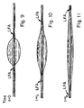
- the arrows labelled "LFA" indicate the location of the liquid-fiber-air interface.
- the arrows labelled "LFA" indicate the location of the liquid-fiber-air interface.
- the arrows labelled "LFA" indicate the location of the liquid-fiber-air interface.
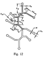
- Figure 12 schematic representation of an orifice of a spinneret useful for producing a spontaneously transportable fiber.
- Figure 13 - schematic representation of an orifice of a spinneret useful for producing a spontaneously transportable fiber.
- Figure 14 - schematic representation of an orifice of a spinneret useful for producing a spontaneously transportable fiber.
- Figure 15 - schematic representation of an orifice of a spinneret useful for producing a spontaneously transportable fiber.
- Figure 16 schematic representation of an orifice of a spinneret useful for producing a spontaneously transportable fiber.
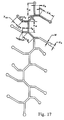
- Figure 17 schematic representation of an orifice of a spinneret having 2 repeating units, joined end to end, of the orifice as shown in Figure 12.
- Figure 18 - schematic representation of an orifice of a spinneret having 4 repeating units, joined end to end, of the orifice as shown in Figure 12.
- FIG 19 photomicrograph of a poly(ethylene terephthalate) fiber cross-section made using a spinneret having an orifice as illustrated in Figure 3 (specific dimensions of spinneret orifice described in Example 1).
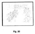
- Figure 20 photomicrograph of a polypropylene fiber cross-section made using a spinneret having an orifice as illustrated in Figure 12 (specific dimensions of spinneret orifice described in Example 2).
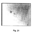
- Figure 21 photomicrograph of a nylon 66 fiber cross-section made using a spinneret having an orifice as illustrated in Figure 12 (specific dimensions of spinneret orifice described in Example 2).
- Figure 22 schematic representation of a poly(ethylene terephthalate) fiber cross-section made using a spinneret having an orifice as illustrated in Figure 13 (specific dimensions of spinneret orifice described in Example 8).
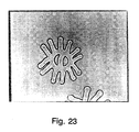
- FIG 23 photomicrograph of a poly(ethylene terephthalate) fiber cross-section made using a spinneret having an orifice as illustrated in Figure 14 (specific dimensions of spinneret orifice described in Example 9).
- Figure 24 photomicrograph of a poly(ethylene terephthalate) fiber cross-section made using a spinneret having an orifice as illustrated in Figure 17 (specific dimensions of spinneret orifice described in Example 10).
- FIG 25 photomicrograph of a poly(ethylene terephthalate) fiber cross-section made using a spinneret having an orifice as illustrated in Figure 18 (specific dimensions of spinneret orifice described in Example 11).
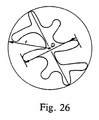
- Figure 26 - schematic representation of a fiber cross-section made using a spinneret having an orifice as illustrated in Figure 12 (Example 1). Exemplified is a typical means of determining the shape factor X.
- Figure 27 photomicrograph of a poly(ethylene terephthalate) fiber cross-section made using a spinneret having an orifice as illustrated in Figure 15 (specific dimensions of spinneret orifice described in Example 12).
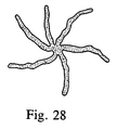
- Figure 28 - schematic representation of a poly(ethylene terephthalate) fiber cross-section made using a spinneret having an orifice as illustrated in Figure 16 (specific dimensions of spinneret orifice described in Example 13).
- Figure 29 - a schematic representation of a desirable groove in a fiber cross-section.
- Figure 30 - a schematic representation of a desirable groove in a fiber cross-section.
- Figure 31 - a schematic representation of a desirable groove in a fiber cross-section illustrating the groove completely filled with fluid.
- Figure 32 - a schematic representation of a groove where bridging is possible in the fiber cross-section.
- Figure 33 a schematic representation of a groove where bridging is possible in the fiber cross-section.
- Figure 34 - a schematic representation of a groove illustrating bridging of the groove by a fluid.
- Figure 35 - a schematic representation of a preferred "H" shape orifice of a spinneret useful for producing a spontaneously transportable fiber.
- Figure 36 a schematic representation of a poly(ethylene terephthalate) fiber cross-section made using a spinneret having an orifice as illustrated in Figure 35.
- Figure 37 - a schematic representation of a preferred "H" shape orifice of a spinneret useful for producing a spontaneously transportable fiber (see Example 23).
- Figure 38 - a schematic representation of a preferred "H" shape orifice of a spinneret useful for producing a spontaneously transportable fiber.
- Figure 39 - a schematic representation depicting a unit cell.
- Figure 40 - a schematic representation of a spinneret having dimensions as specified.
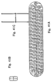
- Figure 41 - a schematic representation of Spinneret I1045 wherein the spinneret holes are oriented such that the cross-flow quench air is directed toward the open end of the H. All dimensions are in units of inches except those containing the letter "W”.
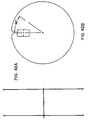
- Figure 42 - a schematic representation of Spinneret I1039 wherein the spinneret holes are oriented in a radial pattern on the face of the spinneret. All dimensions are in units of inches except those containing the letter "W”.
- Figure 43 - a photomicrograph of a cross-section of a helically crimped fiber formed by the process of helically crimping a fiber of this invention wherein the fiber cross-section is not distorted.
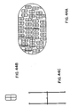
- Figure 44 - a schematic representation of Spinneret I 1046 wherein the spinneret holes are oriented such that the cross-flow quench air is directed toward the open end of the H.
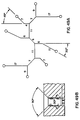
- Figure 45 - a schematic representation of quench air direction relative to the spinneret holes.
- Figure 46 - a schematic representation of Spinneret 1047 wherein spinneret holes are oriented such that the cross-flow quench air was directed toward one side of the H.
- Figure 47 - a photomicrograph of helically crimped fibers of the invention without a distorted cross-section.
- Figure 48 - a photomicrograph of stuffer box crimped fiber having a distorted cross-section.
- Figures 49 and 50 - a schematic representation of a spinneret wherein the spinneret holes are oriented in a diagonal pattern on the face of the spinneret with cross-flow quenching directed toward the fiber bundle.
- Figure 51 - a photomicrograph of a helically crimped fiber prepared by the process of the invention.
- Figure 52 - a graphical representation of absorption times for various microwavable inserts.
- the invention relates to an insert useful in a microwavable food container comprising first and second outer layers and an intermediate layer bonded thereto, and a third outer layer bonded to said second layer wherein said first outer layer comprises a plastic layer, 8, 12 and 26, further comprising openings 6 and 28, said plastic layer being in position to be adjacent to food, 14, in said container, said intermediate layer, 10 and 30, comprises an absorbent material comprising fibers, and said second outer layer, 16 and 32, is a substrate layer which is stable to microwave heating conditions.
- This insert is hereinafter referred to as "Insert A".
- the plastic layer may comprise polyester, nylon or the like.
- the plastic layer is made from polyolefins, such as polypropylene or polyethylene.
- Preferred examples useful in making the plastic layer are heat set polyesters such as poly (ethylene terephthalate). Further examples are Mylar (trademark) polyethylene terephthalate film sold by Du Pont or THERMX (trademark) polyester sold by Eastman Kodak Company. THERMX is a polyester film comprising a copolyester of terephthalic acid and isophthalic acid with 1,4-cyclohexanedimethanol.
- the thickness of the plastic layer can be readily determined by one skilled in the art.
- the plastic layer comprises a metallized layer of heat susceptor thickness.
- the metallized layer is a microwave interactive layer which has been incorporated into disposable laminate materials used to cook the food. Such laminates are characterized by their ability to absorb microwave energy and convert it to heat which may be conductively and radiantly transmitted to the food. Semiconductive materials, ferro-magnetic metals, metal oxides, and thin elemental metals are some of the materials used to form the microwave interactive layer.
- the metallized layer may comprise any electroconductive metal which is capable of converting microwave energy to thermal energy in the form of thin films.
- the method of forming the metal film comprises any convenient film-forming procedure, consistent with the metal employed. For example, for aluminum conventional vapor deposition is the most convenient. Other materials, such as copper, stainless steel, tin oxide, chromium, magnesium, silver and gold can be used. However, aluminum is very inexpensive and has been widely used in the form of aluminum foil as far as the general packaging of food is concerned.
- the plastic layer is in direct physical contact with food providing the maximum amount of heat transfer and browning. Such contact is maintained by the construction and sizing of the container to provide holding pressure in view of the size of the food pieces to be packaged and optionally spacers. Such intimate contact is important to the heating and crisping benefits provided by the present invention.
- the susceptor layer or plastic layer contains a perforation feature comprising a plurality of openings therethrough or a perforated sheet, which allows escape or release of any oil or moisture vapor which the food pieces release during heating.
- the openings may be formed by any method known in the art, such as needle punch or calender roll.
- the openings may be in the form of an organized array as depicted or may be randomly although preferably evenly distributed.
- the openings can be modified either by hole density, size, or placement to add further control over grease and moisture drainage.
- the openings may have an effective diameter in the range of 0.5 mm to 5 mm. They may be shaped in any fashion including circular or elongated. Openings elongated in shape typically have a major axis length of 1/4 to 1/2 inch (0.64 to 1.27 cm) and a minor axis of less than 2 mm.
- the openings allow oil and/or moisture released during microwave heating to be absorbed by the panel or drain therethrough and thus drawn away from the portions thereby further reducing the undesirable softening of the coating and oiliness of the final product as well as substantially reducing excessive oil buildup and heating on the heating panels and thus reduces both spattering and the generation of undesirable burned oil flavor. Also, the oil drainage is important since released oil in contact with the heating panel absorbs excessive amounts of the heat generated which in turn can result in uneven browning.
- the heating layer Preferred for use herein as the heating layer are the metallized films described in U.S. Patent No. 4,267,420 (issued may 12, 1981 to W. A. Brastad) or, less desirably, in U.S. Patent No. 4,258,086 (issued Mar. 24, 1981 to N.J. Beall) each of which are incorporated herein by reference. These materials are widely known and a variety of suitable materials are available from, for example, the 3M Co., James River or from Deposition Technology Inc. (San Diego, CA).
- the metallized layer comprises a plastic sheet or thin film, 20, which typically has a thickness of approximately 0.005 to 0.001 inch (0.013 to 0.003 cm).
- the plastic film, 20, is made from a polyester.
- the plastic sheet or thin film, 20, has applied thereto a very thin coating, 22, having a surface resistivity of approximately 1 to 300 ohms per square inch, and preferably 1 to 10 ohms per square inch when aluminum is the applied metal. It will be understood that a resistivity of 1 ohm per square denotes a heavier or thicker coating than a coating of the same material having a 10 ohms per square resistivity. The greater the resistivity, the more microwave energy which is converted to heat. The practical upper limit to the resistivity is determined by the scorch temperature of the mounting board and the plate separation as described below.
- the thickness of the metal film should be such that the metal film converts a portion of microwave energy incident thereon to thermal energy.
- the thickness varies with the metal employed.
- the metal film generally has a thickness corresponding to an optical density of 0.08 to 0.8.
- the amount of susceptor material(s) must be adequate to allow said materials to absorb a portion of both the electric and the magnetic components of said microwave energy and convert said energy to heat to rapidly brown or crispen the surface of the foil item adjacent thereto without substantially impeding the ability of the microwave energy to penetrate the susceptor material and cook the food item.
- Various methods may be used to measure the amount of susceptor coated on or imbibed in the substrate material to form the composites of this invention.
- D.C. surface resistivities are commonly used.
- Optical density measurements may also be used.
- a number of methods may be used to apply the susceptor materials to the substrate.
- the specific resistance of a coating is susceptible to variation and that within limits the thicker such coating is the less pervious or more opaque it is the passage of microwave energy therethrough. Hence, in order to promote a greater degree of browning, the coating would be thicker than when a less degree of browning is desired. In this way, the browning or crisping can be correlated with the actual dielectric heating of the food piece.
- an additional protective sheet or film of plastic can be laminated onto the side of the metallized layer which is coated with metal.
- the top protective film is preferably of polyester, having substantially the same thickness and properties as the plastic sheet or thin film comprising the metallized layer.
- the metallized layer as described above is substituted by a heating body further comprising a supporting sheet and a non-metal active microwave absorber which has been applied to said supporting sheet.
- U.S. Patent No. 4,190,757 (issued February 26, 1980 to C.H. Turpin) incorporated herein by reference.
- a heating body is described which also comprises a supporting sheet to which an active microwave absorber has been applied.
- the microwave absorber should be applied in a relatively thin paint-like layer, 22.
- the absorber can be any of the four groups of materials including semi-conductors, selected ferromagnetic materials, period 8 oxides and selected dielectric materials (graphite, carbon black, iron oxide or ferrite).
- These particles are dispersed in a nonmetallic (e.g., polymeric) binder which deposit has a thickness within the range from 10 to 300 micrometers, with the particles comprising at least 10% by weight of the deposit as is taught in U.S. Patent No. 4,640,838 incorporated herein by reference.
- a nonmetallic binder e.g., polymeric binder which deposit has a thickness within the range from 10 to 300 micrometers, with the particles comprising at least 10% by weight of the deposit as is taught in U.S. Patent No. 4,640,838 incorporated herein by reference.
- the metal-coated material may be selectively demetallized to provide a pattern of metal of desired form. Suitable selective demetallization procedures are described in U.S. Patent Nos. 4,398,994, 4,552,614 and 4,610,755.
- the metal-coated material next can be adhered to a nonconductive sheet.
- This sheet may comprise structural fibrous stock material, 24, particularly paper or paperboard by conventional laminating procedures using a suitable laminating adhesive, such as a thermosetting resin. It may also be adhered to the fibrous stock material, 24, by using thermal bonding techniques known in the art.
- Patches of microwave interactive material can be formed on a web of plastic.
- This web can be laminated to one side of a web of structural stock material to form a composite web having a plastic layer and a structural stock material layer so that the microwave interactive material is sandwiched between the web of plastic and the web of structural stock material.
- the microwave interactive layer is bonded to and arranged to cover entirely one of the surfaces of a semi-rigid, microwave transparent material, such as paperboard.
- a lamination process can be used wherein the metal side of the susceptor or microwave interactive layer is bonded to paperboard using an adhesive in the same manner that a conventional susceptor is understood by a person of ordinary skill in the art to be bonded to paperboard.
- Microwave heating conditions include temperatures as high as 110°C. and above.
- “Susceptor materials” are materials which are capable of absorbing the electric or magnetic portion of microwave field energy to convert that energy to heat.
- the fibers useful in the present invention have a complex cross-section geometry that results in a surface area that allows for more efficient wetting of the fiber, aqueous or grease transport or a combination of grease and moisture absorption if the appropriate surface energetics are applied.
- surface energetics it is meant that the fibers useful in the invention must satisfy the requirements of the equations described herein which apply to "spontaneously transporting" fibers.
- the fibers are preferably spontaneously transportable.
- the preferred fibers are ones having a hydrophilic lubricant applied thereto or intermittently therein and that are capable of spontaneous transporting of water on the surfaces thereof.
- preferred fibers are also ones having a hydrophobic lubricant applied thereto or intermittently therein and that are capable of spontaneously transporting n-decane on the surfaces thereof.
- some of the fibers useful in the present invention preferably have at least one continuous groove oriented axially along the fiber wherein said fiber satisfies the following equation: (1-X cos ⁇ a ) ⁇ 0, wherein ⁇ a is the advancing contact angle of water measured on a flat film made from the same material as the fiber and having the same surface treatment, if any, X is a shape factor of the fiber cross-section that satisfies the following equation: wherein P w is the wetted perimeter of the fiber and r is the radius of the circumscribed circle circumscribing the fiber cross-section and D is the minor axis dimension across the fiber cross-section.
- some of the fibers useful in the present invention have at least one continuous groove oriented axially along the fiber wherein said fiber satisfies the following equation: (1-X cos ⁇ a ) ⁇ 0, wherein ⁇ a is the advancing contact angle of n-decane measured on a flat film made from the same material as the fiber and having the same surface treatment, if any, X is a shape factor of the fiber cross-section that satisfies the following equation: wherein P w is the wetted perimeter of the fiber and r is the radius of the circumscribed circle circumscribing the fiber cross-section and D is the minor axis dimension across the fiber cross-section.
- the second outer layer is selected from the group consisting of a plastic film layer, paper or paperboard.
- a plastic film layer is preferred. More preferably, the films can be made from polyolefins, such as polypropylene or polyethylene.
- Preferred polyesters useful in making the plastic film layer are heat set polyesters such as heat set poly(ethylene terephthalate) (PET). Further examples are Mylar sold by DuPont or THERMX sold by Eastman Kodak Company. Also, nylon could be used to form the plastic film layer.
- the second outer layer prevents leakthrough and helps spontaneous transport by providing extra wettable surface area.
- the second outer layer is bonded to the intermediate layer.
- the bonding could either be by thermal methods or cohesive methods as described herein.
- the first outer and intermediate layers are bonded together either by any adhesive known in the art or by thermal bonding procedures known in the art.
- the preferred bonding procedure is described by Veratec, Inc. and disclosed in EP-A-0360 929 A1.
- the thermal embossing technique includes films of polyethylene being secured to nonwovens while at the same time having apertures in the film for good fluid penetration.
- the absorbent material of the intermediate layer comprises fibers.
- the geometry of the pore-structure in the fabrics (capillarity), the nature of the solid surface (surface free energy, contact angle), the geometry of the solid surface (surface roughness, grooves, etc.), the chemical/physical treatment of the solid surface (caustic hydrolysis, plasma treatment, grafting, application of hydrophobic/hydrophilic finishes), and the chemical nature of the fluid all can influence liquid transport phenomena in fibrous structures.
- the wettability of a solid surface by a liquid can be characterized by the contact angle that the liquid surface (gas-liquid interface) makes with the solid surface (gas-solid surface).
- a drop of liquid placed on a solid surface makes a contact angle, ⁇ , with the solid surface, as seen in Figure 1A. If this contact angle is less than 90°, then the solid is considered to be wet by the liquid. However, if the contact angle is greater than 90°, such as with water on Teflon (trademark) surface, the solid is not wet by the liquid.
- the contact angle also depends on surface inhomogeneities (chemical and physical, such as roughness), contamination, chemical/physical treatment of the solid surface, as well as the nature of the liquid surface and its contamination.
- Surface free energy of the solid also influences the wetting behavior. The lower the surface energy of the solid, the more difficult it is to wet the solid by liquids having high surface tension. Thus, for example, Teflon, which has low surface energy does not wet with water. (Contact angle for Teflon-water system is 112°.) However, it is possible to treat the surface of Teflon with a monomolecular film of protein, which significantly enhances the wetting behavior.
- the contact angle of poly (ethylene terephthalate) (PET), Nylon 66, and polypropylene with water is 80°, 71°, and 108°, respectively.
- PET polyethylene terephthalate
- Nylon 66 is more wettable than PET.
- the contact angle is >90°, and thus is nonwettable with water.
- the particular geometry of the deep and narrow grooves is very important, for example, grooves which have the feature that the width of the groove at any depth is equal to or less than the width of the groove at the mouth of the groove. If the preferred groove is not achieved, "bridging" of the liquid across the restriction is possible and thereby the effective wetted perimeter (Pw) is reduced.
- the fluid used to wet the fiber to determine the wetted perimeter is reduced.
- the fluid used to wet the fiber to determine the wetted perimeter is, accordingly, water in the case of fibers which spontaneously transport water, and n-decane in the case of fibers which spontaneously transport n-decane. In any case, it is preferred that Pw is substantially equal to the geometric perimeter.
- the number of continuous grooves present in the fiber of the present invention is not critical as long as the required geometry is present (i.e., the fiber satisfies the equation (1-X cos ⁇ a ) ⁇ 0) .
- “Spontaneously transportable” and derivative terms thereof refer to the behavior of a fluid in general and in particular a drop of fluid, such as water or n-decane, when it is brought into contact with a single fiber such that the drop spreads along the fiber. Such behavior is contrasted with the normal behavior of the drop which forms a static ellipsoidal shape with a unique contact angle at the intersection of the liquid and the solid fiber. It is obvious that the formation of the ellipsoidal drop takes a very short time but remains stationary thereafter.
- Figures 2A, 2B, and 2C illustrate spontaneous fluid transport on a fiber surface. The key factor is the movement of the location of the air, liquid, solid interface with time.
- the fiber is spontaneously transportable; if such interface is stationary, the fiber is not spontaneously transportable.
- the spontaneously transportable phenomenon is easily visible to the naked eye for large filaments [>20 denier per filament (>22.22 dtex)] but a microscope may be necessary to view the fibers if they are less than 20 dpf. Colored fluids are more easily seen but the spontaneously transportable phenomenon is not dependent on the color. It is possible to have sections of the circumference of the fiber on which the fluid moves faster than other sections. In such case the air, liquid, solid interface actually extends over a length of the fiber. Thus, such fibers are also spontaneously transportable in that the air, liquid, solid interface is moving as opposed to stationary.
- Spontaneous transportability is basically a surface phenomenon; that is the movement of the fluid occurs on the surface of the fiber. However, it is possible and may in some cases be desirable to have the spontaneously transportable phenomenon occur in conjunction with absorption of the fluid into the fiber.
- the behavior visible to the naked eye will depend on the relative rate of absorption vs. spontaneous transportability. For example, if the relative rate of absorption is large such that most of the fluid is absorbed into the fiber, the liquid drop will disappear with very little movement of the air, liquid, solid interface along the fiber surface whereas if the rate of absorption is small compared to the rate of spontaneous transportability the observed behavior will be that of wicking or transport as exemplified in Figures 2A through 2C.
- the fibers useful in the invention achieve high fluid transport by varying the fiber cross-section, there are few if any limitations on the material used to make the fibers. Hybrids are also possible. This allows one to vary the fiber type to meet different packaging needs whether it be to maintain a homogenous packaging structure for recycling purposes (for example, the use of a cellulose-based fiber for an absorber in a paper tray package) or to meet certain cooking conditions such as very high oven temperatures.
- a designed calender roll which will provide better, more uniform bonding of the fibers.
- Another method useful in the invention is the application of a spun-bonded polyester layer to the top of the fiber nonwoven during calendering. This layer is made of continuous, small denier per filament (dtex) PET fibers and is very thin. It acts as a net to trap and hold the other fibers.
- Another advantage to the spun bonded layer is that calender bonding need not be as heavily compressed since the spun bonded layer acts to hold the fibers together. This improves transport and holding capacity.
- Adhesion tension is the product of the surface tension ⁇ and cos ⁇ a .
- certain surface treatments have the undesirable feature of reducing the effective surface tension of aqueous fluids such that it is substantially reduced from its theoretical potential.
- preferred surface treatments are those which result in the effective adhesion tension of the fluid to be transported to be as close to the theoretical adhesion tension as possible.
- the effective adhesion tension is measured by the method described in Example 22 hereof using the appropriate fluid.
- Preferred fibers of the invention have an effective adhesion tension in water of greater than 38 dynes/cm. More preferred is greater than 45 dynes/cm.
- Plasma treatment is a preferred surface treatment since the effective adhesion tension is close to the theoretical adhesion tension. It is not desired to be bound by any particular theory or mechanism; however, it is believed that for some surface treatments, such as use of potassium lauryl phosphate and/or PEG 600 monolaurate, a portion of the deposited surface treatment material partially solubilizes in the fluid, at least at the fluid/surface interface, substantially reducing the surface tension of the liquid, thereby reducing the effective adhesion tension but not substantially affecting the contact angle ( ⁇ a ).
- a fiber of the invention can be characterized as having one or more "channels" or "unit cells".
- the fiber cross-section shown in Figure 40 depicts a unit cell.
- a unit cell is the smallest effective transporting unit contained within a fiber.
- the total fiber is the sum of all unit cells.
- each unit cell has a height, H, and a width, W.
- S l is the leg thickness and S b is the backbone thickness.
- the other dimensional parameters of the cross-section are important for obtaining the desired type of spontaneous transportability. For example, it has been found that the number of channels and the thickness of the areas between unit cells, among other things, are important for optimizing the uphill flux value of the fiber.
- the equation for q (including the additional equations mentioned above) is particularly useful for determining the optimum channel width to maximize uphill flux (fluid movement against the adverse effects of gravity; sin ⁇ > 0 in the equation for h).
- the equation for q is also useful for calculating values for downhill flux (fluid movement enhanced by gravity; sin ⁇ ⁇ 0 in the equation for h) for which there is no optimum channel width.
- the equation for q and the equations for p, A, and A f were derived for a fiber containing one or more rectangularly-shaped channels, but the basic principles used to derive these equations could be applied to channels having a wide variety of geometries.
- a fiber of the present invention is capable of spontaneously transporting water on the surface thereof.
- Distilled water can be employed to test the spontaneous transportability phenomenon; however, it is often desirable to incorporate a minor amount of a colorant into the water to better visualize the spontaneous transport of the water, so long as the water with colorant behaves substantially the same as pure water under test conditions.
- aqueous Syltint Poly Red (trademark) from Milliken Chemicals to be a useful solution to test the spontaneous transportability phenomenon.
- the Syltint Poly Red solution can be used undiluted or diluted significantly, e.g., up to 50x with water.
- a fiber of the present invention is also capable of spontaneously transporting a multitude of other aqueous fluids.
- Aqueous fluids are those fluids comprising 50% or more water by weight, preferred is 75% or more water by weight, most preferred is 90% or more water by weight.
- Another class of preferred fibers useful in the present invention is capable of spontaneously transporting n-decane on the surface thereof.
- the n-decane can be colored for better visualization.
- such a fiber is also typically capable of spontaneously transporting other hydrophobic fluids such as various types of grease, cyclohexane, xylene or ⁇ -pinene.
- the fibers useful in the present invention have both a major and a minor axis of symmetry and that these fibers be helically crimped so that quenching by air occurs perpendicular to the major axis of the fiber.
- the process involves the following steps: extruding a conventional PET fiber forming polymer; passing the polymer through spinneret hole shapes; orienting said spinneret hole shapes to the cross-flow quench air so that quenching occurs perpendicular to the major axis of the fiber; controlling the quench air; applying hydrophilic lubricants; taking up the fibers at conventional speeds; drafting the fibers using conventional drafting (single steam stage in steam or two stage in water and steam); adding an additional amount of hydrophilic lubricant; and relaxing the drawn fibers in a heated chamber to develop the helical crimp.
- the full development of the helical crimp in the fibers useful in the present invention is realized by relaxing the fibers in heat.
- the temperature of the heating step is above the T g of the fibers.
- the helical crimp is formed due to differences in the orientation of the fiber across the diameter of the cross section. This difference in orientation is built into the fiber by following the steps listed in the process previously described. The higher the difference in orientation, the more likely that the filament will form a helical crimp.
- One method of determining the rate of fluid transport of a single fiber includes measuring single filament wetting perimeters as shown in Example 19 herein.
- hydrophilic lubricants which can be used to lubricate the fibers useful in this invention include the following:
- the fibers of the present invention preferably have a surface treatment applied thereto.
- Such surface treatment may or may not be critical to obtain the required spontaneous transportability property.
- the nature and criticality of such surface treatment for any given fiber can be determined by a skilled artisan through routine experimentation using techniques known in the art and/or disclosed herein.
- a preferred surface treatment is a coating of a hydrophilic lubricant on the surface of the fiber. Such coating is typically uniformly applied at a level of at least 0.05 weight percent, with 0.1 to 2 weight percent being preferred.
- Preferred hydrophobic lubricants include mineral oil based ones.
- Lubricant X comprises 80-83% mineral oil, 7-9% ethoxylated sorbitan monolaurate, 9.5-11.5% sorbitan monolaurate, and 80-90 ppm of chlorine dioxide.
- Yet another preferred hydrophobic lubricant is peanut oil based.
- Polyester A a high inherent viscosity homopolymer comprising or consisting of poly(ethylene) terephthalate) (PET) is used as the material for the film
- PET poly(ethylene) terephthalate)
- the uncoated PET is also preferred for transport of hydrophobic material.
- the number of crimps/inch (crimps/cm) in the fiber is greater than 4 (10) and the crimp amplitude is less than 2 mm.
- the fibers of the invention can be tailored to work either as a grease absorber, a moisture absorber, or a combination of both just by varying the fiber lubricant. This allows the nonwoven fibers to be optimized for the food item being cooked.
- polyesters or copolyesters that are well known in the art and can be prepared using standard techniques, such as, by polymerizing dicarboxylic acids or esters thereof and glycols.
- the dicarboxylic acid compounds used in the production of polyesters and copolyesters are well known to those skilled in the art and illustratively include terephthalic acid, isophthalic acid, p,p'-diphenyldicarboxylic acid, p,p'-dicarboxydiphenylethane, p,p'-dicarboxydiphenylhexane, p,p'-dicarboxydiphenyl ether, p,p'-dicarboxyphenoxyethane, and the like, and the dialkylesters thereof that contain from 1 to 5 carbon atoms in the alkyl groups thereof.
- LK 5570 and Raycalube are preferred lubricants for both oil (and n-decane) and water. Where both transport of oil and water are desired, LK 5570 or Raycalube are the lubricants of choice. Where transport of oil is exclusively desired, Lubricant X is the preferred lubricant.
- Suitable aliphatic glycols for the production of polyesters and copolyesters are the acyclic and alicyclic aliphatic glycols having from 2 to 10 carbon atoms, especially those represented by the general formula HO(CH2) p OH, wherein p is an integer having a value of from 2 to 10, such as ethylene glycol, trimethylene glycol, tetramethylene glycol, and pentamethylene glycol, decamethylene glycol, and the like.
- Suitable aliphatic glycols include 1,4-cyclohexanedimethanol, 3-ethy1-1,5-pentanediol, 1,4-xylylene, glycol, 2,2,4,4-tetramethyl-1,3-cyclobutanediol, and the like.
- One can also have present a hydroxylcarboxyl compound such as 4-hydroxybenzoic acid, 4-hydroxyethoxybenzoic acid, or any of the other hydroxylcarboxyl compounds known as useful to those skilled in the art.
- mixtures of the above dicarboxylic acid compounds or mixtures of the aliphatic glycols can be used and that a minor amount of the dicarboxylic acid component, generally up to 10 mole percent, can be replaced by other acids or modifiers such as adipic acid, sebacic acid, or the esters thereof.
- polyester poly(ethylene terephthalate) (PET).
- polyamides such as a nylon, e.g., nylon 66 or nylon 6
- polypropylene such as polyethylene
- cellulose esters such as cellulose triacetate or cellulose diacetate.
- a single fiber of the present invention preferably has a denier per filament of between 1 and 1,000, more preferred is between 5 and 70.
- Fiber shape and fiber/fluid interface variables can be manipulated to increase fluid transport rate per unit weight of fiber (flux) by accomplishing the following:
- surfactants provide very good wetting of surfaces by lowering fluid surface tension and decreasing contact angle and thereby yield low adhesion tension at the surface. Therefore, it is important that the surfactant possess some attraction for the polyester surface (hydrophobic) and also for water (hydrophilic). It is also preferred that the surfactant bind tightly to the polyester surface and at the same time present high hydrophilicity to the water side of the interface.
- Another surface treatment is to subject the fibers to oxygen plasma treatment, as taught in, for example, Plastics Finishing and Decoration , Chapter 4, Ed. Don Satas, Van Nostrand Reinhold Company (1986).
- Spinnerets useful in the present invention must have a specific geometry in order to produce fibers that will spontaneously transport aqueous fluids.
- Figures 12-18 illustrate spinneret orifices which will prepare fibers of a geometry suitable for use in the present invention.
- W is between 0.064 millimeters (mm) and 0.12 mm.
- X2 is X4 is 2W ⁇ 0.5W;
- W is between 0.064 mm and 0.12 mm;
- X20 is X22 is 3W ⁇ W;
- X24 is 4W ⁇ 2W;
- X26 is X28 is X30 is 2W ⁇ 0.5W;
- X32 is and ⁇ 10 is 45° ⁇ 15°.
- each Leg B can vary in length from 0 to and each Leg A can vary in length from 0 to
- W is between 0.064 mm and 0.12 mm;
- X34 is 2W ⁇ 0.5W;
- X36 is X38 is ⁇ 12 is ⁇ 14 is and
- W is between 0.064 mm and 0.12 mm;
- X42 is X44 is 11W ⁇ 5W;
- X46 is 11W ⁇ 5W;
- X48 is 24W ⁇ 10W;
- X50 is 38W ⁇ 13W;
- X52 is X54 is
- X56 is 11W ⁇ 5W;
- X58 is 7W ⁇ 5W;
- X60 is 17W ⁇ 7W;
- X62 is 28W ⁇ 11W;
- X64 is 24W ⁇ 10W;
- X66 is 17W ⁇ 7W;
- X68 is 2W ⁇ 0.5W;
- ⁇ 16 is ⁇ 18 is 45° ⁇ 15°; and
- ⁇ 20 is 45° ⁇ 15°.
- W is between 0.064 mm and 0.12 mm
- X72 is X74 is X76 is 12W ⁇ 4W
- X78 is 8W ⁇ 4W
- X80 is 24W ⁇ 12W
- X82 is 18W ⁇ 6W
- X84 is X86 is 16W ⁇ 6W
- X88 is 24W ⁇ 12W
- X90 is 18W ⁇ 6W
- X92 is 2W ⁇ 0.5W
- ⁇ 22 is 135° ⁇ 30°
- ⁇ 24 is ⁇ 26 is 45° ⁇ 15°
- ⁇ 28 is 45° ⁇ 15°
- ⁇ 30 is 45° ⁇ 15°
- ⁇ 32 is 45° ⁇ 15°
- ⁇ 34 is 45° ⁇ 15°
- ⁇ 36 is 45° ⁇ 15°
- ⁇ 38 is 45° ⁇ 15°.
- Figure 35 depicts a preferred "H" shape spinneret orifice of the invention.
- W1 is between 60 and 150», ⁇ is between 80° and 120°, S is between 1 and 20, R is between 10 and 100, T is between 10 and 300, U is between 1 and 25, and V is between 10 and 100.
- W1 is between 65 and 100», ⁇ is between 90° and 110°, S is between 5 and 10, R is between 30 and 75, T is between 30 and 80, U is between 1.5 and 2, and V is between 30 and 75.
- Figure 36 depicts a poly(ethylene terephthalate) fiber cross-section made from the spinneret orifice of Figure 35.
- W2 is less than 20»,
- W3 is between 10 and 300
- W4 is between 20 and 200
- W5 is between 5 and 50
- and W6 is between 20 and 200».
- W2 is less than 10
- W3 is between 20 and 100
- W4 is between 20 and 100
- W5 is between 5 and 20».
- Figure 26 illustrates the method for determining the shape factor, X, of the fiber cross-section.
- r 37.5 mm
- P w 355.1 mm
- D 49.6 mm
- the invention further comprises an insert useful in a microwavable food container comprising a first layer and a second layer bonded thereto, wherein said first layer comprises a susceptor layer or a plastic layer, and said second layer comprises absorbent material comprising fibers and is in position to be adjacent to food in said container, wherein said second layer comprises at least one fiber having at least one continuous groove oriented axially along the fiber and wherein said fiber satisfies the equations as described hereinabove.
- This insert is hereinafter referred to as "Insert B".
- the first layer and the absorbent layer of Insert B are virtually identical to the first outer layer and the intermediate layer as described for Insert A with the exception that the susceptor or plastic layer does not comprise openings.
- the absorbent layer, 2 and 30, of Insert B is the layer positioned to contact the food.
- the first layer, 4 and 26, of Insert B can be bonded conventionally to paperboard or properly adhered to another flexible substrate such as paper or to a plastic sheet.
- the invention further comprises an insert useful in microwavable food container comprising an absorbing pad, said pad comprising: microwave radiation transparent and grease absorbing fibers wherein at least one said fiber has at least one continuous groove oriented axially along the fiber and wherein said fiber satisfies the equations as previously described herein for spontaneously transporting n-decane or water.
- the fibers used in the pad are identical to the fibers used in Inserts A and B.
- the absorbing pad as described hereinafter is referred to as "Insert C", 18. It is preferred that a vapor tight microwave radiation transparent enclosures surrounds Insert C.
- the pad material it is preferred to select a pad material that can have the same surface area as the food which is supported on the pad and can still so completely adsorb or otherwise hold all the grease contained in that food, that after the food is cooked and removed from the enclosure, the enclosure will not drip grease even when the opening through which the food was removed is lowermost on the enclosure.
- a pad material that can have the same surface area as the food which is supported on the pad and can still so completely adsorb or otherwise hold all the grease contained in that food, that after the food is cooked and removed from the enclosure, the enclosure will not drip grease even when the opening through which the food was removed is lowermost on the enclosure.
- such pads that can hold in the range of 0.1 to 0.15 grams of grease per square centimeter of surface area have been found useful for packaging conventional bacon strips.
- the enclosure may be made from one or more conventional polymeric packaging materials such as nylon/ionomer composites of the type available from Curwood, Inc., New London, Wisconsin; or a polyester/polyethylene laminate such as is sold under the trade designation "Scotchpak” by Minnesota Mining and Manufacturing Company, St. Paul, Minnesota. Also the enclosure could be made from a metal foil.
- the package according to the present invention could be vented by puncturing, as with a fork, to allow the escape of steam and other vapors during cooking
- the package includes means that will automatically vent the package during cooking.
- That means for venting the enclosure could comprise pre-formed openings in the enclosure that are initially closed by a manually removable cover (e.g., a piece of pressure sensitive adhesive coated tape).
- that means for venting comprises a deposit of microwave radiation absorbing material adhered to a heat sensitive material forming at least a portion of the enclosure, which microwave radiation absorbing material will be heated by exposure to microwave radiation and will automatically cause a vent to form or open in the heat sensitive material during microwave cooking of the food.
- the inserts of this invention can conform to a number of different packaging geometries. For instance, they can be used in the conventional flat sheet form for an "as is" cooking sheet. They can be incorporated into the bottom of a package, again as a flat cooking surface. These inserts can also be incorporated into three dimensional package structures such as cooking sleeves for the "pocket” sandwiches, as cooking bags for popcorn and similar foods, boxes for microwave french fries and tater tots, and as pouches for chicken, bacon, etc.
- the absorbing pads conforming to the structure of Insert C of this invention can be used as stand-alone absorbers to be inserted into packages as needed. It could also be produced as a roll stock and then cut and modified to fit various package structures.
- flavorants such as spices, smoke flavorings, butter, etc. could be dispersed in the fibers useful in the invention. The flavorants would then be released into food during microwave heatup. For effective flavor delivery, the fibers should be in good contact with the food.
- flavorants can be useful to provide more pleasant food aromas when opening a microwave food oven door. It is believed that the same theories applying to the spontaneous transport of fluids would apply to transport of a flavorant such as those exemplified herein.
- the fibers of the present invention can be in the form of crimped or uncrimped tows or staple fibers comprising a plurality of the fibers of the present invention.
- the fibers of the present invention can be prepared by techniques known in the art and/or disclosed herein using a novel spinneret of the present invention or other spinneret that will result in a fiber cross-section of the appropriate geometry and properties.
- a process useful in the present invention can be described as a process comprising heating a material capable of forming a fiber at or above its melting point followed by extruding said heated material through at least one spinneret having at least one orifice capable of forming the desired fiber.
- the fiber may be drafted and/or thermally stabilized.
- the fiber thus formed may then optionally be treated with a surface treatment such as a hydrophilic coating or plasma treatment as described hereinbefore.
- microwavable inserts of the invention are particularly useful in the microwave oven cooking of pan-fried frozen food items such as fish, chicken and vegetables. They are sometimes useful in the heating of breaded food.
- the present invention also finds use in connection with pizza rolls, potatoes, e.g., hashbrown patties, sausages, corn dogs and the like.
- inserts of the invention typically are rectangularly shaped, other shapes, whether regular such as oval, wedge, log, circular or irregular or combinations thereof, can also be employed.
- Poly(ethylene terephthalate) (PET) polymer of 0.6 I.V. was used in this example.
- I.V. is the inherent viscosity as measured at 25°C at a polymer concentration of 0.50 g/100 milliliters (mL) in a suitable solvent such as a mixture of 60% phenol and 40% tetra-chloroethane by weight.
- the polymer was dried to a moisture level of ⁇ 0.003 weight percent in a Patterson Conaform dryer at 120°C for a period of 8 hours.
- the polymer was extruded at 283°C through an Egan extruder, 1.5-inch (3.81 cm) diameter, with a length to diameter ratio of 28:1.
- the fiber was extruded through an eight orifice spinneret wherein each orifice is as shown in Figure 12 wherein W is 0.084 mm, X2 is 4W, X4 is 2W, X6 is 6W, X8 is 6W, X10 is 7W, X12 is 9W, X14 is 10W, X16 is 11W, X18 is 6W, ⁇ 2 is 0°, ⁇ 4 is 45°, ⁇ 6 is 30°, and ⁇ 8 is 45°.
- the polymer throughput was 7 pounds (3.18 kg)/hour.
- the air quench system has a cross-flow configuration. The quench air velocity at the top of the screen was an average of 294 ft (89.61 m)/minute.
- the average velocity of the quench air was 285 ft (86.87 m)/minute, and at a distance of 14 inches (35.56 cm) from the top of the screen the average quench air velocity was 279 ft (85.04 m)/minute.
- the average air velocity was 340 ft (103.63 m)/minute. The rest of the screen was blocked. Spinning lubricant was applied via ceramic kiss rolls.
- the lubricant has a general composition as follows: it is a potassium lauryl phosphate (PLP) based lubricant having poly(ethylene glycol) 600 monolaurate (70% by weight) and polyoxyethylene (5) potassium lauryl phosphate (30% by weight). An emulsion of the above lubricant with water (90%) was used as the spinning lubricant. The lubricant level on the fiber samples was 1.5%. Fibers of 20 dpf (denier per filament) (22.22 dtex) were wound at 3,000 meters per minute (MPM) on a Barmag SW4SL winder. A photomicrograph of a cross-section of this fiber is shown in Figure 9 (150x magnification).
- PPM potassium lauryl phosphate
- the single fiber was tested for spontaneous surface transportation of an aqueous solution which was aqueous Syltint Poly Red (obtained from Milliken Chemicals) which is 80 weight % water and 20 weight % red colorant.
- aqueous Syltint Poly Red obtained from Milliken Chemicals
- the single fiber of 20 dpf (22.22 dtex) spontaneously surface transported the above aqueous solution.
- the value of the "X" parameter (as defined hereinbefore) for these fibers was 1.7.
- PET film of 0.02 inch (0.05 cm) thickness was compression molded from the same polymer as that used for making the above fiber.
- Contact angle of distilled water on the above film was measured in air with a contact angle goniometer. The contact angle was 71.7°.
- Another sample of the same film as above was sprayed with the same lubricant as used for making the fiber in this example at 1.5% level.
- the contact angle of distilled water on the PET film sprayed with the lubricant was 7°.
- Polyhexamethylene adipamide (nylon 66) was obtained from Du Pont [Zytel (trademark) 42]. The polymer was extruded at 279°C. A spinneret as shown in Figure 12 was used to form 46 dpf (51.11 dtex) fiber at 255 meters/minute speed. The specific dimensions of the spinneret orifices were the same as described in Example 1 except that ⁇ 2 was 30° instead of 0°. The quenching conditions were the same as those for obtaining PET fiber as in Example 1. A photomicrograph of the fiber cross-section is shown in Figure 21 (150x magnification). The lubricant level on the fiber was 1.8% by weight. The same lubricant as used in the PET fiber was used (Example 1).
- This nylon 66 fiber spontaneously transported the aqueous Syltint Poly Red solution on the fiber surface.
- the value of the "X" parameter for this fiber was 1.9.
- Nylon 66 film of 0.02 inch (0.05 cm) thickness was compression molded from the same polymer as that used for making the fiber of Example 2.
- Contact angle of distilled water on the above film was measured in air with a contact angle goniometer. The contact angle was 64°.
- Another sample of the same film as above was sprayed with the same lubricant as used for making the fiber in this example at the 1.8% level.
- the contact angle of distilled water on the nylon 66 film sprayed with the lubricant was 2°.
- Polypropylene polymer was obtained from Shell Company (Grade 5C14). It was extruded at 279°C. A spinneret as shown in Figure 3 was used to form 51 dpf (56.67 dtex) fiber at 2,000 MPM speed. The specific dimensions of the spinneret orifices were the same as in Example 2. The quenching conditions were the same as those for obtaining PET fiber. A photomicrograph of the fiber cross-section is shown in Figure 10 (375x magnification). The lubricant level on the fiber was 2.6%. The same lubricant as used in PET fiber was used (Example 1). The polypropylene fiber spontaneously transported the aqueous Syltint Poly Red solution on the fiber surface.
- Cellulose acetate was blended with PEG 400 polymer and small quantities of antioxidant and thermal stabilizer. The blend was melt extruded at 270°C. A spinneret as shown in Figure 3 was used to form 115 dpf (127.78 dtex) fiber at 540 meters/minute speed. The specific dimensions of the spinneret orifices were the same as in Example 2. No forced quench air was used. The lubricant level on the fiber was 1.6%. The same lubricant as used in the PET fibers (Example 1) was used. The cellulose acetate fiber spontaneously transported the aqueous Syltint Poly Red solution on the fiber surface. The value of the "X" parameter for this fiber was 1.8.
- PET fiber of Example 1 was made without any spinning lubricant at 20 dpf (22.22 dtex). A single fiber did not spontaneously transport the aqueous Syltint Poly Red solution along the fiber surface.
- PET fiber of circular cross-section was made.
- the denier per filament of the fiber was 20 (22.22 dtex). It had 1.5% of the lubricant used in Example 1.
- a single fiber did not spontaneously transport the aqueous Syltint Poly Red solution along the fiber surface.
- PET fiber of Example 5 was treated with oxygen plasma for 30 seconds.
- Model "Plasmod" oxygen plasma equipment was used. Exciter power is provided by the RF generator operating at 13.56 MHz frequency.
- the plasma treatment was conducted at a constant level of 50 watts power.
- the oxygen plasma treated fiber spontaneously transported the aqueous Syltint Poly Red solution along the fiber. This fiber was tested again after washing five times and after 3 days and the spontaneously transportable behavior with the above aqueous solution was still observed.
- a PET film of the same material as that of the fiber was subjected to the oxygen plasma treatment under the same conditions as those used for the fiber sample.
- the average contact angle of the oxygen plasma treated film with distilled water in air was observed to be 26° as measured by a contact angle goniometer.
- the corresponding contact angle for the control PET film (not exposed to the oxygen plasma) was 70°.
- the significant reduction in contact angle upon subjecting the untreated PET fiber to the oxygen plasma treatment renders it to be spontaneously surface transportable for aqueous solutions.
- PET Poly(ethylene terephthalate) (PET) polymer of 0.6 I.V. was used in this example. It was extruded through a spinneret having eight orifices as shown in Figure 13 wherein W is 0.084 mm, X20 is 17W, X22 is 3W, X24 is 4W, X26 is 60W, X28 is 17W, X30 is 2W, X32 is 72W, ⁇ 10 is 45°, Leg B is 30W, and Leg A is 26W. The rest of the processing conditions were the same as those described in Example 1. A 100 dpf (111.11 dtex) fiber was spun at 600 MPM. A sketch of the cross-section of the fiber is shown in Figure 22.
- the lubricant level on the fiber was 1%.
- the same lubricant as used in Example 1 was used.
- the above fiber spontaneously transported the aqueous Syltint Poly Red solution along the fiber surface.
- the value of the "X" parameter for this fiber was 1.5.
- Poly(ethylene terephthalate) polymer of 0.6 I.V. was used in this example. It was extruded through a spinneret having eight orifices as shown in Figure 14 wherein W is 0.10 mm, X34 is 2W, X36 is 58W, X38 is 24W, ⁇ 12 is 20°, ⁇ 14 is 28°, and n is 6. The rest of the extruding and spinning conditions were the same as those described in Example 1.
- a photomicrograph of the fiber cross-section is shown in Figure 23 (585x magnification). A 20 dpf (22.22 dtex) fiber was spun at 3000 MPM. The lubricant level on the fiber was 1.7%. The same lubricant as used in Example 1 was used. The above fiber spontaneously transported the aqueous Syltint Poly Red solution along the fiber surface. The value of the "X" parameter for this fiber was 2.4.
- PET Poly(ethylene terephthalate) (PET) polymer of 0.6 I.V. was used in this example.
- the polymer was extruded through a spinneret having four orifices as shown in Figure 17 wherein the dimensions of the orifices are repeats of the dimensions described in Example 2.
- the rest of the processing conditions were the same as those described in Example 1 unless otherwise stated.
- a 200 dpf (222.22 dtex) fiber was spun at 600 MPM.
- the polymer throughput was 7 lbs (3.18 kg)/hr.
- An optical photomicrograph of the fiber is shown in Figure 14 (150x magnification).
- the lubricant level on the fiber was 2.0%.
- the same lubricant as used in Example 1 was used.
- the above fiber spontaneously transported the aqueous Syltint Poly Red solution along the fiber surface.
- the value of the "X" parameter for this fiber was 2.2.
- PET Poly(ethylene terephthalate) (PET) polymer of 0.6 I.V. was used in this example.
- the polymer was extruded through a spinneret having two orifices as shown in Figure 18 wherein the dimensions of the orifices are repeats of the dimensions described in Example 2.
- the rest of the processing conditions were the same as those described in Example 1.
- a 364 dpf (404.44 dtex) fiber was spun at 600 MPM.
- the cross-section of the fiber is shown in Figure 25 (150x magnification).
- the lubricant level on the fiber was 2.7%.
- the same lubricant as used in Example 1 was used.
- the above fiber spontaneously transported the aqueous Syltint Poly Red solution along the fiber surface.
- the value of the "X" parameter for this fiber was 2.1.
- PET Poly(ethylene terephthalate) (PET) polymer of 0.6 I.V. was used in this example. It was extruded through a spinneret having eight orifices as shown in Figure 15 wherein W is 0.10 mm, X42 is 6W, X44 is 11W, X46 is 11W, X48 is 24W, X50 is 38W, X52 is 3W, X54 is 6W, X56 is 11W, X58 is 7W, X60 is 17W, X62 is 28W, X64 is 24W, X66 is 17W, X68 is 2W, ⁇ 16 is 45°, ⁇ 18 is 45°, and ⁇ 20 is 45°.
- Example 2 The rest of the processing conditions were the same as those described in Example 1.
- a 100 dpf (111.11 dtex) fiber was spun at 600 MPM.
- the cross-section of the fiber is shown in Figure 27.
- the lubricant level on the fiber was 1%.
- the same lubricant as used in Example 1 was used.
- the above fiber spontaneously transported the aqueous Syltint Poly Red solution along the fiber surface.
- the value of the "X" parameter for this fiber was 1.3.
- PET polymer of 0.6 I.V. is used in this example. It is extruded through a spinneret having 8 orifices as shown in Figure 16 wherein W is 0.10 mm, X72 is 8W, X74 is 8W, X76 is 12W, X78 is 8W, X80 is 24W, X82 is 18W, X84 is 8W, X86 is 16W, X88 is 24W, X90 is 18W, X92 is 2W, ⁇ 22 is 135°, ⁇ 24 is 90°, ⁇ 26 is 45°, ⁇ 28 is 45°, ⁇ 30 is 45°, ⁇ 32 is 45°, ⁇ 34 is 45°, ⁇ 36 is 45° and ⁇ 38 is 45°.
- a 20 dpf (22.22 dtex) fiber is spun at 3,000 m/min.
- the rest of the processing conditions are the same as those used in Example 1.
- the lubricant level on the fiber is 1%.
- the cross-section of the fiber is shown in Figure 28. This fiber spontaneously transports the aqueous Syltint Poly Red solution along the fiber surface.
- the "X" value for this fiber is 2.1.
- the first set of samples produced consisted of various laminate structures.
- Samples 1 and 2 consist of 3 layer structures with a perforated pinholed susceptor on top, the spontaneously wettable nonwoven fibers (fibers which satisfy the equations as described herein) in the middle and Mylar film on the back.
- the 8-lobe polyester spontaneously wettable fibers were 10 denier per filament (11.11 dtex) with LK 5570 as defined herein hydrophilic lubricant.
- the Mylar film was 1.2 mils thick.
- the nonwoven weight was 35 g/yd2 (0.04 kg/m2) while 2 had a nonwoven weight of 70 g/yd2 (0.08 kg/m2).
- Samples 3 and 4 Insert B type structures, were two layered structures with the nonwoven bonded to the top of the susceptor. As with the previous samples, Sample 3 had a nonwoven weight of 35 g/yd2 (0.04 kg/m2) while Sample 4 had a weight of 70 g/yd2 (0.08 kg/m2) (fabric doubled over prior to bonding). Thermal bonding of the sheets was performed using a polyester powder adhesive. Pinholes were placed into the susceptor sheet using a nonwoven needler and had a density of 50/inch2 (2.54 cm2) while being 1/32 inch (0.08 cm) in diameter.
- Microwave tests could not be performed due to problems with the available susceptor film.
- the susceptor sheet had a metallized density much greater than specified causing it to overheat quickly during cooking resulting in curled up film due to poor heat stability. Therefore, only cold static tests were preferred.
- Samples 1-4 were cut to 4.7 in. (11.94 cm) square and tested by placing a fixed quantity of colored water or soybean oil on the center of the sheet using a pipette and measuring the time required for absorption. Five ml of colored water were used while only 3 ml of soybean oil were administered. Results are tabulated in Table I. As seen, the lower nonwoven weight of 35 g/yd2 (0.04 kg/m2) was insufficient and did not produce any transport.
- EXAMPLE 15 (Example of the Invention) - Preliminary Screening of Lubricant X Hydrophobic Lubricant (mineral oil based lubricant comprising 80-83% mineral oil, 7-9% ethoxylated sorbitan monolaurate, 9.5-11.5% sorbitan monolaurate, and 80-90 ppm of chlorine dioxide)
- Samples were prepared by thermal bonding as described in Example 15 at 190°C for 60 seconds with two different nonwovens. Both consist of 80% spontaneously wettable polyester fibers and 20% binder fibers as described above. Samples 7-10 consisted of spontaneously wettable polyester fibers which were 5.5 denier/filament (6.11 dtex) x 2.0 inches (5.08 cm) long, having a Lubricant X hydrophobic lubricant applied thereto, and weighing 27.8 g/yd2 (0.03 kg/m2).
- Sample 11 consisted of 17 denier/filament (18.89 dtex) x 2.0 inch (5.08 cm) helical crimped "H" cross-section fibers with LK 5570 as defined herein and a nonwoven weight of 49.8 g/yd2 (0.06 kg/m2). This nonwoven also has a high level of directionality in the machine direction. All samples tested used two layers of the nonwoven giving sample weights of 55.6 and 99.5 g/yd2 (0.07 and 0.12 kg/m2) for the Lubricant X coated and "H" cross-sectioned samples, respectively.
- the nonwovens were bonded into the standard 3-layer (Insert A type) and 2-layer (Insert B type) absorber structure as before except this time a different susceptor was used.
- 3-layer samples MicroCrisp (trademark) susceptor film was used with a needled hole density of 65 holes/inch2 (2.54 cm2) and a slightly more clumped pattern.
- 2-layer samples regular susceptor film was laminated to a paperboard substrate which reduced the curling and cracking. Samples used were approximately 5 inches square (12.7 cm2). Two half-strips of bacon were laid on the sample and cooked in the microwave oven for varying times. Observations and results are tabulated in Table II.
- the 3-layer structures worked well for both fibers although the "H" section seemed to work much better even with the hydrophilic lubricant. This is most likely due to the fact that the fiber denier (kg/m) and the sheet weight are higher.
- one of the 3-layer "H” sheets was administered with 3 ml of colored water via a pipette as in previous tests. This liquid was completely absorbed in 25 seconds, far superior to any of the previous samples. Water transport for this sample is superior to other spontaneously wettable polyester fiber samples although it should be pointed out that the increased hole density and nonwoven weight also contributed to the improved performance.
- the Hormel (trademark) microwave bacon pad was included in this testing.
- the denier per filament of the Hormel pad was 1.6 (1.44 dtex).
- samples of each of the nonwovens were saturated in fluid (canola oil or water) for 1 minute, removed, and held in air for one minute to allow dripping to complete. Samples were weighed before and after to determine saturation liquid content. This data is tabulated in Table III.
- the Hormel pad is superior in holding capacity, but it is also a much thicker pad being 1/8 inch (0.32 cm) thick which gives more internal void space for retaining the fluids.
- the spontaneously wettable polyester fiber samples were all basically 1 layer of nonwoven folded and creased except for the last one in the table. Proper formation and bulking of the nonwoven should give much improved holding capacity which would more than likely be superior to the Hormel sheet.
- EXAMPLE 18 (Example of the Invention) - (Insert C Type) Cooking Tests in Hormel Bacon Pouch
- the Hormel absorbing pad was removed and various nonwovens of approximately the same size replaced and the pouch then microwaved.
- the average denier per filament of the cross-section of the fibers used in the Hormel absorbing pad was 2.5 (2.78 dtex).
- the Hormel pad prior to cooking was 6.6 grams. After cooking, it weighed 36.9 g indicating a fluid absorption of 30.3 grams. No dripping occurred after microwaving with this pad. Cooking time is 3-4 minutes which is much longer than with the susceptor sheets used in Example 16.
- Various polyester fibers were tested to determine aqueous fluid transport velocities.
- a single drop of aqueous Syltint Poly Red was applied to a single fiber as in Example 1 and the transport monitored using a microscope with an image analysis system. The velocity of the fluid front as it moved along the fiber was then determined from the image analyzer and compared for different fibers which are listed in Table A.
- Sample A is a standard round cross-section, low denier (kg/m) fiber produced commercially.
- the fiber was made from standard poly(ethylene terephthalate). It did not spontaneously wet so no velocity was obtained.
- Samples D and E are the same fiber with different crimping methods. The helical crimp was found to be less detrimental than the stufferbox crimp on transport properties.
- Sample A is a typical commercial fiber.
- This lubricant is similar to LK 5570 except the level of antistat is greater.
- Samples D and E are the same fiber with different crimping methods.
- Samples were produced conforming to the description of Insert B as described for the invention using a calender bonding system.
- the fibers were 5.5 by 2 inch denier, 8-leg, spontaneously wettable with Lubricant X hydrophobic lubricant (same as Sample 7-above).
- Mylar and Thermx films were run in-line with the nonwoven through the calender roll.
- Calender roll temperatures were 230°C
- system pressure was 300 psi
- throughput speed was 60 ft/minute (18.29 m/minute).
- the calender roll had an embossing pattern consisting of squares 1/32 inch (0.08 cm) on each side and a hole density of 250/inch2 (2.54 cm2). No binder fiber was used in this bonding.
- Thermx film had less well defined embossing sites but also exhibited better fluid transport.
- the Thermx film as also not heatset. Fluid transport with these samples was slightly worse than non-calendered samples. This is most likely due to the crushing and compacting of void space and transport channels. It is also believed that much of the lubricant was "burned off" in the calender rolls which would lower oil transport. Bonding between the film and fibers was good. Addition of a perforated top layer as described for the invention for Insert A resulted in very good fluid transport.
- a sample of the laminate was trimmed and placed in the bottom of a box of Kirt (trademark) fried chicken (ConAgra Foods) and microwaved. The laminate successfully wicked up the grease as it ran down to the bottom resulting in chicken with much better taste and texture over chicken which was cooked alone or with paper towels only.
- Adhesion tension tests were performed using water, n-decane, and canola oil as the test fluids. Adhesion tensions were measured using a wetting balance. Samples were prepared from Polyester A (a high inherent viscosity poly(ethylene terephthalate) homopolymer) film coated with the various lubricants. The values of adhesion tensions and contact angles for the different lubricants and the different test fluids are listed in Table IV. Surface tensions for the water, n-decane and canola oil measured on a Wilhelmy Plate were 72.4 dynes/cm, 24.5 dynes/cm, and 34.4 dynes/cm, respectively. Adhesion tension is defined herein as the surface tension (liquid-vapor) multiplied by the cosine of the contact angle.
- Lubricant X is a preferred hydrophobic lubricant. It exhibits lower adhesion tensions for water and reasonably high values for the oil and n-decane.
- uncoated Polyester A alone is one of the more hydrophobic surfaces tested. This translates to good transport of oily substances and poor transport of aqueous fluids.
- LK 5570 and Raycalube both show high adhesion tensions for both oil (and n-decane) and water. Based on the data, however, LK 5570 and Raycalube are good transporters of aqueous and oily substances. In fact, the LK 5570 and Raycalube appear to be better at oil transport than the Lubricant X.
- Lubricant X is the lubricant of choice.
- the X-factor for the fiber ideally must lie between the minimum required factors for the two fluids.
- the minimum X-factor are approximate only. They do not reflect the lubricant distribution on/in the fiber, the packing of the fibers and the bonding on the fibers to the backsheet. Packing and bonding of the fibers relate to the effective number of "fluid channels" that will be present in the final structure.
- the backsheets used in Examples 21 et seq. were either metallized PET or plain THERMX.
- the metallized PET is commercial, oriented and heatset PET susceptor which is 1 mil thick.
- the THERMX is as cast and is 0.5 mils thick.
- One important difference between these two films is the level of crystallinity.
- the PET is oriented and heatset (which provides considerable crystallinity) in order to give it the necessary thermal and dimensional stability. Because THERMX crystallizes so quickly, it can be used in its cast, amorphous state.
- Applications for THERMX as a susceptor base are currently being pursued in the laboratory because of its rapid crystallization rate which provides excellent dimensional stability at high temperatures.
- the X-factor for these fibers is around 1.9 to 2.1 which is sufficiently close to 2.12 that it can be assumed that the fiber meets the criteria for spontaneous wetting (with LK 5570) within experimental error. It is sufficiently below the 2.75 for the Lubricant X so here spontaneous wetting is not predicted.
- Saturation capacities listed in Table VII show Sample 1 to have a slightly larger holding capacity. Note that the difference between the saturation capacities is fairly small and could be attributable to other circumstances.
- sample 3 has twice as much fiber as Sample 1 but its absorption rate is 3 times faster. Saturation capacities for the two structures are the same. Note, however, that Sample 3 can hold more oil by weight since the capacities listed are based on the original dry weight (and the dry weight of Sample 3 is larger since it contains more fiber).
- Sample 4 is an example of a THERMX backed structure. It has a very low nonwoven weight (only 33 g/yd2) and uses a high denier per filament (dtex) fiber (12 denier). Absorption times with this sample are longer than with Samples 1 through 3 but still less than the Wavealites. In addition, its nonwoven weight is less than half that of the Wavealites sample. Its saturation capacity is lower than any of the other samples. This is believed to be attributable to the lower nonwoven weight and higher denier per filament. Also note that all of Samples 1 through 3 have higher saturation capacities than the Wavealites.
- french fries were packaged in small single-serve paperboard containers.
- a susceptor film was bonded to the bottom of the package to enhance browning.
- french fries were soggy and greasy even with the standard susceptor.
- the susceptor film was replaced with a piece of the Sample 2 absorber described earlier. After cooking with this film, the french fries were much crispier and not soggy, enhancing overall flavor.
- the normal french bread pizza is packaged in a film wrap and comes with a metallized susceptor/carton for cooking.
- Cooking with the original carton produced a pizza crust which was browned but soggy in some places, particularly the bottom center where moisture could not escape. Since the susceptor film could not be removed from this carton, a layer of the susceptor absorber was placed over it.
- the modified structure produced a slightly more brown crust, no sogginess on the bottom and more uniform melting of the cheese on top. All of this was done with 30 seconds less cooking time.
- the normal package for this product is a metallized paper sleeve which fits around the sandwich. Cooking with this structure produced a fairly good sandwich although some cold spots were prevalent. A film of grease was noticeable on the metallized paperboard sleeve after cooking. To modify the package, a susceptor absorber was placed inside the sleeve over the standard metallized film. There was noticeable fluid absorption on the pad after cooking. Both samples were dry but the modified package was slightly better. The modified package also produced a more uniformly heated and browned sandwich in the same cooking time.
- a plain English muffin was cooked on both a piece of conventional susceptor film and a susceptor absorber like Sample 2.
- the muffin was more crispy on the standard susceptor structure. Also there was very little moisture absorbed on the susceptor absorber film. For breads, it is probably better that the food be in direct contact with the metallized film so that sufficient browning may occur.
Landscapes
- Engineering & Computer Science (AREA)
- Food Science & Technology (AREA)
- Mechanical Engineering (AREA)
- Life Sciences & Earth Sciences (AREA)
- Textile Engineering (AREA)
- Laminated Bodies (AREA)
- Cookers (AREA)
- Nonwoven Fabrics (AREA)
- General Preparation And Processing Of Foods (AREA)
- Packages (AREA)
- Food-Manufacturing Devices (AREA)
Abstract
Description
- This invention relates to inserts useful in microwavable containers. The invention can further comprise fibers which are capable of spontaneously transporting fluid on the surface thereof.
- There is a need in the microwave food industry for inserts useful in microwavable containers that are more efficient in removing excess grease and moisture from food during cooking in a microwave oven.
- A wide variety of inserts useful in microwavable food containers have been developed to improve the quality of food cooked in a microwave oven. For instance, it is known to place a liquid absorbent pad within a package for absorbing food byproducts such as moisture and grease exuded from food during cooking in a microwave oven (U.S. Patent No. 4,873,101). Such pads must not only provide sufficient capacity for the quantity of food byproducts produced during cooking, but must withstand the elevated temperatures required to adequately cook the precooked or cured foods discussed above without degradation.
- Similarly, U.S. Patents 4,954,356 and 4,857,342 disclose a microwavable package for storing and cooking a food product including an absorbent bed enclosed within a sealed plastic sleeve. Also, U.S. Patent 4,950,524 discloses a bacon pad made of liquid absorbent wood fibers. U.S. Patent 4,786,513 discloses a package of sliced bacon containing an absorbent blotter means.
- U.S. Patent 4,873,101 discloses a package of food containing a substantial amount of water and solidified grease that can be cooked within the package in a microwave oven. The package further comprises a pad adjacent the food comprising microwave radiation transparent generally hydrophobic liquid grease absorbing materials that are capable of holding the amount of grease in the food when it is melted.
- U.S. Patent No. 5,094,869 describes a food degreaser which uses a layer of absorbent fiber on the inside of a wicking material envelope.
- Other known grease absorbing pads have been found to be useful, such as the insulating product which is sold under the trade designation "Thinsulate" by Minnesota Mining and Manufacturing Company, St. Paul, Minnesota, in densities of 40, 100 and 200 grams/m² and absorbs or holds 15, 16 and 9 1/2 times its own weight of grease, respectively; the products sold under the trade designation "Oil Sorbent" and "Insorb Industrial Wipe" by Minnesota Mining and Manufacturing Company, St. Paul, Minnesota, which have densities of 36 and 70 grams/m², respectively, and absorb or hold 14 and 8 times their own weight in grease, respectively.
- For example, in U.S. Patent No. 4,865,854 pads of blown microfibers are described which are constructed of a composition comprising a blend containing substantially equal parts by weight of polypropylene and poly 4-methylpentene-1 (PMP), 0.16 cm (0.062 inch) in thickness and thermally embossed on both sides with a 0.40 cm (0.156 inch) hexagonal pattern and having densities in the range of nine and one half (9 1/2) to six (6) times their weight in grease.
- However, conventional absorbent pads absorb both water and various greases from the food. This is undesirable in that if part of the absorbent capacity of the pad is occupied by moisture, insufficient capacity may remain for grease.
- It is also desirable in many cases for water exuded from a food in the form of steam during cooking to be maintained in close proximity to the food as to evenly distribute heat within the package and to reduce the cooking for the food. An additional problem occurs during extended storage and transportation of a package containing a food having substantial amounts of water and grease. A pad that absorbs water as well as grease will tend to gradually absorb water from the food. Thus, a subsequent measurement will show that the weight of the food has been reduced compared to the weight at the time the package was sealed.
- Therefore, there is a need in the art to find new microwavable inserts which show improvement over the standard microwavable inserts that are useful in microwavable food containers. This is true especially in the area of optimization of grease or moisture transport depending on whether the food is prone to greasiness or a combination thereof.
- Also disclosed in the art are microwavable inserts comprising a plastic film with a thin metal coating or "metallized film". The metallized film is generally used in direct contact with a food item. Part of the microwave energy passes through to heat the food item dielectrically while part is converted to heat by the metallized film to sear the coating in contact therewith. U.S. Patent No. 4,703,148 describes this particular art in detail.
- Also known in the art are microwavable inserts having two layers, the first of which is a top layer consisting of an absorbent layer made from fibers, the second of which is a metallized susceptor layer. These inserts are known as "Wavealites" (trademark).
- In PCT Publication WO 90/12130 published October 18, 1990, fibers are disclosed which are capable of spontaneously transporting water and other hydrophilic fluids on their surfaces. Additionally, other fibers of sufficient chemical composition and geometry are capable of spontaneously transporting n-decane and other hydrophobic fluids. Such fibers will be referred to herein as "spontaneously transportable fibers" or, alternatively, "spontaneously wettable fibers." We have unexpectedly discovered that use of fibers of sufficiently complex geometry, especially spontaneously transportable fibers, when incorporated into micro-wavable cooking structures, results in improved wetting and aids in aqueous and/or nonaqueous transport of fluids released during microwave cooking with appropriate surface energetics.
-
- The invention relates to absorbent structures as defined in
independent Claims - For some of the fibers useful in the present invention, it is preferred that X is greater than 1.2, more preferably greater than 2.5, most preferably greater than 4. Also, it is preferred that 2


- For fibers to be able to spontaneously wet one fluid and not another, X must lie between the minimum required values for X for the two fluids. For example, to have a fiber with no lubricant which will spontaneously transport canola oil and not water requires an X-factor higher than 1.09 but lower than 2.75.
- For the fibers that spontaneously transport water, it is preferred that the fiber of the invention satisfies the formula:

wherein γLA is the surface tension of water in air in dynes/cm, ρ is the fiber density in grams/cc, and dpf is the denier of the single fiber. For the fibers that spontaneously transport n-decane, it is preferred that the fiber of the invention satisfies the formula:
wherein γLA is the surface tension of n-decane in air in dynes/cm, ρ is the fiber density in grams/cc, and dpf is the denier per filament (dtex) of the single fiber. - Figure 1 - an enlarged cross-sectional view of a preferred embodiment of the invention, i.e., Insert B, as described herein.
- Figure 2 - a perspective view of a preferred embodiment of the invention, Insert A, as described herein.
- Figure 3 - an enlarged cross-sectional view of a preferred embodiment of the invention, Insert A, as described herein.
- Figure 4 - an enlarged cross-sectional view of a preferred embodiment of the invention, Insert C, as described herein.
- Figure 5 - a cross-sectional view of a typical known susceptor structure.
- Figure 6 - a perspective view of a preferred embodiment of the invention, Insert B, as described herein.
- Figure 7 - a perspective view of a preferred embodiment of the invention, Insert A, as described herein.
- Figure 8 - schematic representation of a three dimensional view of an absorbant fiber of the invention illustrating the swelling of superabsorbant material out of a fiber groove upon transport of a fluid.
- Figure 9 - illustration of the behavior of a drop of an aqueous fluid which has just contacted a fiber that is spontaneously transportable at time = 0. The arrows labelled "LFA" indicate the location of the liquid-fiber-air interface.
- Figure 10 - illustration of the behavior of a drop of an aqueous fluid on a fiber that is spontaneously transportable at

- Figure 11 - illustration of the behavior of a drop of an aqueous fluid on a fiber that is spontaneously transportable at

- Figure 12 - schematic representation of an orifice of a spinneret useful for producing a spontaneously transportable fiber.
- Figure 13 - schematic representation of an orifice of a spinneret useful for producing a spontaneously transportable fiber.
- Figure 14 - schematic representation of an orifice of a spinneret useful for producing a spontaneously transportable fiber.
- Figure 15 - schematic representation of an orifice of a spinneret useful for producing a spontaneously transportable fiber.
- Figure 16 - schematic representation of an orifice of a spinneret useful for producing a spontaneously transportable fiber.
- Figure 17 - schematic representation of an orifice of a spinneret having 2 repeating units, joined end to end, of the orifice as shown in Figure 12.
- Figure 18 - schematic representation of an orifice of a spinneret having 4 repeating units, joined end to end, of the orifice as shown in Figure 12.
- Figure 19 - photomicrograph of a poly(ethylene terephthalate) fiber cross-section made using a spinneret having an orifice as illustrated in Figure 3 (specific dimensions of spinneret orifice described in Example 1).
- Figure 20 - photomicrograph of a polypropylene fiber cross-section made using a spinneret having an orifice as illustrated in Figure 12 (specific dimensions of spinneret orifice described in Example 2).
- Figure 21 - photomicrograph of a nylon 66 fiber cross-section made using a spinneret having an orifice as illustrated in Figure 12 (specific dimensions of spinneret orifice described in Example 2).
- Figure 22 - schematic representation of a poly(ethylene terephthalate) fiber cross-section made using a spinneret having an orifice as illustrated in Figure 13 (specific dimensions of spinneret orifice described in Example 8).
- Figure 23 - photomicrograph of a poly(ethylene terephthalate) fiber cross-section made using a spinneret having an orifice as illustrated in Figure 14 (specific dimensions of spinneret orifice described in Example 9).
- Figure 24 - photomicrograph of a poly(ethylene terephthalate) fiber cross-section made using a spinneret having an orifice as illustrated in Figure 17 (specific dimensions of spinneret orifice described in Example 10).
- Figure 25 - photomicrograph of a poly(ethylene terephthalate) fiber cross-section made using a spinneret having an orifice as illustrated in Figure 18 (specific dimensions of spinneret orifice described in Example 11).
- Figure 26 - schematic representation of a fiber cross-section made using a spinneret having an orifice as illustrated in Figure 12 (Example 1). Exemplified is a typical means of determining the shape factor X.
- Figure 27 - photomicrograph of a poly(ethylene terephthalate) fiber cross-section made using a spinneret having an orifice as illustrated in Figure 15 (specific dimensions of spinneret orifice described in Example 12).
- Figure 28 - schematic representation of a poly(ethylene terephthalate) fiber cross-section made using a spinneret having an orifice as illustrated in Figure 16 (specific dimensions of spinneret orifice described in Example 13).
- Figure 29 - a schematic representation of a desirable groove in a fiber cross-section.
- Figure 30 - a schematic representation of a desirable groove in a fiber cross-section.
- Figure 31 - a schematic representation of a desirable groove in a fiber cross-section illustrating the groove completely filled with fluid.
- Figure 32 - a schematic representation of a groove where bridging is possible in the fiber cross-section.
- Figure 33 - a schematic representation of a groove where bridging is possible in the fiber cross-section.
- Figure 34 - a schematic representation of a groove illustrating bridging of the groove by a fluid.
- Figure 35 - a schematic representation of a preferred "H" shape orifice of a spinneret useful for producing a spontaneously transportable fiber.
- Figure 36 - a schematic representation of a poly(ethylene terephthalate) fiber cross-section made using a spinneret having an orifice as illustrated in Figure 35.
- Figure 37 - a schematic representation of a preferred "H" shape orifice of a spinneret useful for producing a spontaneously transportable fiber (see Example 23).
- Figure 38 - a schematic representation of a preferred "H" shape orifice of a spinneret useful for producing a spontaneously transportable fiber.
- Figure 39 - a schematic representation depicting a unit cell.
- Figure 40 - a schematic representation of a spinneret having dimensions as specified.
- Figure 41 - a schematic representation of Spinneret I1045 wherein the spinneret holes are oriented such that the cross-flow quench air is directed toward the open end of the H. All dimensions are in units of inches except those containing the letter "W".
- Figure 42 - a schematic representation of Spinneret I1039 wherein the spinneret holes are oriented in a radial pattern on the face of the spinneret. All dimensions are in units of inches except those containing the letter "W".
- Figure 43 - a photomicrograph of a cross-section of a helically crimped fiber formed by the process of helically crimping a fiber of this invention wherein the fiber cross-section is not distorted.
- Figure 44 - a schematic representation of Spinneret I 1046 wherein the spinneret holes are oriented such that the cross-flow quench air is directed toward the open end of the H.
- Figure 45 - a schematic representation of quench air direction relative to the spinneret holes.
- Figure 46 - a schematic representation of Spinneret 1047 wherein spinneret holes are oriented such that the cross-flow quench air was directed toward one side of the H.
- Figure 47 - a photomicrograph of helically crimped fibers of the invention without a distorted cross-section.
- Figure 48 - a photomicrograph of stuffer box crimped fiber having a distorted cross-section.
- Figures 49 and 50 - a schematic representation of a spinneret wherein the spinneret holes are oriented in a diagonal pattern on the face of the spinneret with cross-flow quenching directed toward the fiber bundle.
- Figure 51 - a photomicrograph of a helically crimped fiber prepared by the process of the invention.
- Figure 52 - a graphical representation of absorption times for various microwavable inserts.
- The invention relates to an insert useful in a microwavable food container comprising first and second outer layers and an intermediate layer bonded thereto, and a third outer layer bonded to said second layer wherein
said first outer layer comprises a plastic layer, 8, 12 and 26, further comprisingopenings
said intermediate layer, 10 and 30, comprises an absorbent material comprising fibers, and
said second outer layer, 16 and 32, is a substrate layer which is stable to microwave heating conditions. This insert is hereinafter referred to as "Insert A". The plastic layer may comprise polyester, nylon or the like. Preferably, the plastic layer is made from polyolefins, such as polypropylene or polyethylene. Preferred examples useful in making the plastic layer are heat set polyesters such as poly (ethylene terephthalate). Further examples are Mylar (trademark) polyethylene terephthalate film sold by Du Pont or THERMX (trademark) polyester sold by Eastman Kodak Company. THERMX is a polyester film comprising a copolyester of terephthalic acid and isophthalic acid with 1,4-cyclohexanedimethanol. - The thickness of the plastic layer can be readily determined by one skilled in the art.
- In a preferred embodiment, the plastic layer comprises a metallized layer of heat susceptor thickness.
- The metallized layer is a microwave interactive layer which has been incorporated into disposable laminate materials used to cook the food. Such laminates are characterized by their ability to absorb microwave energy and convert it to heat which may be conductively and radiantly transmitted to the food. Semiconductive materials, ferro-magnetic metals, metal oxides, and thin elemental metals are some of the materials used to form the microwave interactive layer. The metallized layer may comprise any electroconductive metal which is capable of converting microwave energy to thermal energy in the form of thin films. The method of forming the metal film comprises any convenient film-forming procedure, consistent with the metal employed. For example, for aluminum conventional vapor deposition is the most convenient. Other materials, such as copper, stainless steel, tin oxide, chromium, magnesium, silver and gold can be used. However, aluminum is very inexpensive and has been widely used in the form of aluminum foil as far as the general packaging of food is concerned.
- The plastic layer is in direct physical contact with food providing the maximum amount of heat transfer and browning. Such contact is maintained by the construction and sizing of the container to provide holding pressure in view of the size of the food pieces to be packaged and optionally spacers. Such intimate contact is important to the heating and crisping benefits provided by the present invention.
- For Insert A, the susceptor layer or plastic layer contains a perforation feature comprising a plurality of openings therethrough or a perforated sheet, which allows escape or release of any oil or moisture vapor which the food pieces release during heating. The openings may be formed by any method known in the art, such as needle punch or calender roll. The openings may be in the form of an organized array as depicted or may be randomly although preferably evenly distributed. The openings can be modified either by hole density, size, or placement to add further control over grease and moisture drainage.
- The openings may have an effective diameter in the range of 0.5 mm to 5 mm. They may be shaped in any fashion including circular or elongated. Openings elongated in shape typically have a major axis length of 1/4 to 1/2 inch (0.64 to 1.27 cm) and a minor axis of less than 2 mm.
- The openings allow oil and/or moisture released during microwave heating to be absorbed by the panel or drain therethrough and thus drawn away from the portions thereby further reducing the undesirable softening of the coating and oiliness of the final product as well as substantially reducing excessive oil buildup and heating on the heating panels and thus reduces both spattering and the generation of undesirable burned oil flavor. Also, the oil drainage is important since released oil in contact with the heating panel absorbs excessive amounts of the heat generated which in turn can result in uneven browning.
- Preferred for use herein as the heating layer are the metallized films described in U.S. Patent No. 4,267,420 (issued may 12, 1981 to W. A. Brastad) or, less desirably, in U.S. Patent No. 4,258,086 (issued Mar. 24, 1981 to N.J. Beall) each of which are incorporated herein by reference. These materials are widely known and a variety of suitable materials are available from, for example, the 3M Co., James River or from Deposition Technology Inc. (San Diego, CA). The metallized layer comprises a plastic sheet or thin film, 20, which typically has a thickness of approximately 0.005 to 0.001 inch (0.013 to 0.003 cm). The plastic film, 20, is made from a polyester. The plastic sheet or thin film, 20, has applied thereto a very thin coating, 22, having a surface resistivity of approximately 1 to 300 ohms per square inch, and preferably 1 to 10 ohms per square inch when aluminum is the applied metal. It will be understood that a resistivity of 1 ohm per square denotes a heavier or thicker coating than a coating of the same material having a 10 ohms per square resistivity. The greater the resistivity, the more microwave energy which is converted to heat. The practical upper limit to the resistivity is determined by the scorch temperature of the mounting board and the plate separation as described below.
- By the terminology, "heat susceptor thickness", it is intended that the thickness of the metal film should be such that the metal film converts a portion of microwave energy incident thereon to thermal energy. The thickness varies with the metal employed. For aluminum, the metal film generally has a thickness corresponding to an optical density of 0.08 to 0.8. In any event, the amount of susceptor material(s) must be adequate to allow said materials to absorb a portion of both the electric and the magnetic components of said microwave energy and convert said energy to heat to rapidly brown or crispen the surface of the foil item adjacent thereto without substantially impeding the ability of the microwave energy to penetrate the susceptor material and cook the food item.
- Various methods may be used to measure the amount of susceptor coated on or imbibed in the substrate material to form the composites of this invention. To quantify the amount of metal coated on a film, for example, D.C. surface resistivities are commonly used. Optical density measurements may also be used.
- A number of methods may be used to apply the susceptor materials to the substrate.
- It will be appreciated that the specific resistance of a coating is susceptible to variation and that within limits the thicker such coating is the less pervious or more opaque it is the passage of microwave energy therethrough. Hence, in order to promote a greater degree of browning, the coating would be thicker than when a less degree of browning is desired. In this way, the browning or crisping can be correlated with the actual dielectric heating of the food piece.
- Because of the thinness of the material constituting the coating, it has very little thermal mass. Thicknesses of only 0.5 to 20 x 10⁻⁶ inch (1.27 to 50.8 x 10⁻⁶ cm) can be readily realized. The thickness, of course, is correlated with the resistivity, and whatever coating material that is selected should have a thickness such as to provide a surface resistivity falling within the range hereinbefore given.
- If desired, an additional protective sheet or film of plastic can be laminated onto the side of the metallized layer which is coated with metal. In this instance, the top protective film is preferably of polyester, having substantially the same thickness and properties as the plastic sheet or thin film comprising the metallized layer.
- In another preferred embodiment, the metallized layer as described above is substituted by a heating body further comprising a supporting sheet and a non-metal active microwave absorber which has been applied to said supporting sheet.
- Materials useful in substituting for the metallized layer, 22, are described in U.S. Patent No. 4,190,757 (issued February 26, 1980 to C.H. Turpin) incorporated herein by reference. In U.S. Patent No. 4,190,757, a heating body is described which also comprises a supporting sheet to which an active microwave absorber has been applied. The microwave absorber should be applied in a relatively thin paint-like layer, 22. The absorber can be any of the four groups of materials including semi-conductors, selected ferromagnetic materials,
period 8 oxides and selected dielectric materials (graphite, carbon black, iron oxide or ferrite). These particles are dispersed in a nonmetallic (e.g., polymeric) binder which deposit has a thickness within the range from 10 to 300 micrometers, with the particles comprising at least 10% by weight of the deposit as is taught in U.S. Patent No. 4,640,838 incorporated herein by reference. - The metal-coated material may be selectively demetallized to provide a pattern of metal of desired form. Suitable selective demetallization procedures are described in U.S. Patent Nos. 4,398,994, 4,552,614 and 4,610,755. The metal-coated material next can be adhered to a nonconductive sheet. This sheet may comprise structural fibrous stock material, 24, particularly paper or paperboard by conventional laminating procedures using a suitable laminating adhesive, such as a thermosetting resin. It may also be adhered to the fibrous stock material, 24, by using thermal bonding techniques known in the art.
- Patches of microwave interactive material can be formed on a web of plastic. This web can be laminated to one side of a web of structural stock material to form a composite web having a plastic layer and a structural stock material layer so that the microwave interactive material is sandwiched between the web of plastic and the web of structural stock material.
- The microwave interactive layer is bonded to and arranged to cover entirely one of the surfaces of a semi-rigid, microwave transparent material, such as paperboard.
- In a preferred bonding process, a lamination process can be used wherein the metal side of the susceptor or microwave interactive layer is bonded to paperboard using an adhesive in the same manner that a conventional susceptor is understood by a person of ordinary skill in the art to be bonded to paperboard.
- "Microwave heating conditions" include temperatures as high as 110°C. and above.
- "Susceptor materials" are materials which are capable of absorbing the electric or magnetic portion of microwave field energy to convert that energy to heat.
- The fibers useful in the present invention have a complex cross-section geometry that results in a surface area that allows for more efficient wetting of the fiber, aqueous or grease transport or a combination of grease and moisture absorption if the appropriate surface energetics are applied. By "surface energetics" it is meant that the fibers useful in the invention must satisfy the requirements of the equations described herein which apply to "spontaneously transporting" fibers. The fibers are preferably spontaneously transportable. The preferred fibers are ones having a hydrophilic lubricant applied thereto or intermittently therein and that are capable of spontaneous transporting of water on the surfaces thereof. Similarly, preferred fibers are also ones having a hydrophobic lubricant applied thereto or intermittently therein and that are capable of spontaneously transporting n-decane on the surfaces thereof.
- In particular, some of the fibers useful in the present invention preferably have at least one continuous groove oriented axially along the fiber wherein said fiber satisfies the following equation:

ϑa is the advancing contact angle of water measured on a flat film made from the same material as the fiber and having the same surface treatment, if any,
X is a shape factor of the fiber cross-section that satisfies the following equation:
wherein
Pw is the wetted perimeter of the fiber and r is the radius of the circumscribed circle circumscribing the fiber cross-section and D is the minor axis dimension across the fiber cross-section. - It is also preferred that some of the fibers useful in the present invention have at least one continuous groove oriented axially along the fiber wherein said fiber satisfies the following equation:

ϑa is the advancing contact angle of n-decane measured on a flat film made from the same material as the fiber and having the same surface treatment, if any,
X is a shape factor of the fiber cross-section that satisfies the following equation:
wherein
Pw is the wetted perimeter of the fiber and r is the radius of the circumscribed circle circumscribing the fiber cross-section and D is the minor axis dimension across the fiber cross-section. - The second outer layer is selected from the group consisting of a plastic film layer, paper or paperboard. A plastic film layer is preferred. More preferably, the films can be made from polyolefins, such as polypropylene or polyethylene. Preferred polyesters useful in making the plastic film layer are heat set polyesters such as heat set poly(ethylene terephthalate) (PET). Further examples are Mylar sold by DuPont or THERMX sold by Eastman Kodak Company. Also, nylon could be used to form the plastic film layer.
- The second outer layer prevents leakthrough and helps spontaneous transport by providing extra wettable surface area. The second outer layer is bonded to the intermediate layer. The bonding could either be by thermal methods or cohesive methods as described herein.
- The first outer and intermediate layers are bonded together either by any adhesive known in the art or by thermal bonding procedures known in the art. The preferred bonding procedure is described by Veratec, Inc. and disclosed in EP-A-0360 929 A1. The thermal embossing technique includes films of polyethylene being secured to nonwovens while at the same time having apertures in the film for good fluid penetration.
- The absorbent material of the intermediate layer comprises fibers. There are several factors which influence the flow of liquids in fibrous structures. The geometry of the pore-structure in the fabrics (capillarity), the nature of the solid surface (surface free energy, contact angle), the geometry of the solid surface (surface roughness, grooves, etc.), the chemical/physical treatment of the solid surface (caustic hydrolysis, plasma treatment, grafting, application of hydrophobic/hydrophilic finishes), and the chemical nature of the fluid all can influence liquid transport phenomena in fibrous structures.
- The three important variables fundamental to the liquid transport behavior are (a) surface tension of the liquid, (b) wettability or the contact angle of the liquid with the solid, and (c) the geometry of the solid surface. Typically, the wettability of a solid surface by a liquid can be characterized by the contact angle that the liquid surface (gas-liquid interface) makes with the solid surface (gas-solid surface). Typically, a drop of liquid placed on a solid surface makes a contact angle, ϑ, with the solid surface, as seen in Figure 1A. If this contact angle is less than 90°, then the solid is considered to be wet by the liquid. However, if the contact angle is greater than 90°, such as with water on Teflon (trademark) surface, the solid is not wet by the liquid. Thus, it is desired to have a minimum contact angle for enhanced wetting, but definitely, it must be less than 90°. However, the contact angle also depends on surface inhomogeneities (chemical and physical, such as roughness), contamination, chemical/physical treatment of the solid surface, as well as the nature of the liquid surface and its contamination. Surface free energy of the solid also influences the wetting behavior. The lower the surface energy of the solid, the more difficult it is to wet the solid by liquids having high surface tension. Thus, for example, Teflon, which has low surface energy does not wet with water. (Contact angle for Teflon-water system is 112°.) However, it is possible to treat the surface of Teflon with a monomolecular film of protein, which significantly enhances the wetting behavior. Thus, it is possible to modify the surface energy of fiber surfaces by appropriate lubricants/finishes to enhance liquid transport. The contact angle of poly (ethylene terephthalate) (PET), Nylon 66, and polypropylene with water is 80°, 71°, and 108°, respectively. Thus, Nylon 66 is more wettable than PET. However, for polypropylene, the contact angle is >90°, and thus is nonwettable with water.
- The second property of fundamental importance to the phenomena of liquid transport is surface tension of the liquid.
- The third property of fundamental importance to the phenomena of liquid transport is the geometry of the solid surface. Although it is known that grooves enhance fluid transport in general, it has been discovered as described PCT Publication WO 90/12130 published October 18, 1990, that particular geometries and arrangements of deep and narrow grooves on fibers and treatments thereof which allow for the spontaneous surface transport of aqueous fluids in single fibers. Thus preferred fibers for use herein are those with a combination of properties wherein an individual fiber is capable of spontaneously transporting water or n-decane on its surface.
- Also, the particular geometry of the deep and narrow grooves is very important, for example, grooves which have the feature that the width of the groove at any depth is equal to or less than the width of the groove at the mouth of the groove. If the preferred groove is not achieved, "bridging" of the liquid across the restriction is possible and thereby the effective wetted perimeter (Pw) is reduced. Of course, the fluid used to wet the fiber to determine the wetted perimeter (Pw) is reduced. Of course, the fluid used to wet the fiber to determine the wetted perimeter is, accordingly, water in the case of fibers which spontaneously transport water, and n-decane in the case of fibers which spontaneously transport n-decane. In any case, it is preferred that Pw is substantially equal to the geometric perimeter.
- The number of continuous grooves present in the fiber of the present invention is not critical as long as the required geometry is present (i.e., the fiber satisfies the equation

- Typically there are at least 2 grooves present, and preferably less than 10.
- "Spontaneously transportable" and derivative terms thereof refer to the behavior of a fluid in general and in particular a drop of fluid, such as water or n-decane, when it is brought into contact with a single fiber such that the drop spreads along the fiber. Such behavior is contrasted with the normal behavior of the drop which forms a static ellipsoidal shape with a unique contact angle at the intersection of the liquid and the solid fiber. It is obvious that the formation of the ellipsoidal drop takes a very short time but remains stationary thereafter. Figures 2A, 2B, and 2C illustrate spontaneous fluid transport on a fiber surface. The key factor is the movement of the location of the air, liquid, solid interface with time. If such interface moves just after contact of the liquid with the fiber, then the fiber is spontaneously transportable; if such interface is stationary, the fiber is not spontaneously transportable. The spontaneously transportable phenomenon is easily visible to the naked eye for large filaments [>20 denier per filament (>22.22 dtex)] but a microscope may be necessary to view the fibers if they are less than 20 dpf. Colored fluids are more easily seen but the spontaneously transportable phenomenon is not dependent on the color. It is possible to have sections of the circumference of the fiber on which the fluid moves faster than other sections. In such case the air, liquid, solid interface actually extends over a length of the fiber. Thus, such fibers are also spontaneously transportable in that the air, liquid, solid interface is moving as opposed to stationary.
- Spontaneous transportability is basically a surface phenomenon; that is the movement of the fluid occurs on the surface of the fiber. However, it is possible and may in some cases be desirable to have the spontaneously transportable phenomenon occur in conjunction with absorption of the fluid into the fiber. The behavior visible to the naked eye will depend on the relative rate of absorption vs. spontaneous transportability. For example, if the relative rate of absorption is large such that most of the fluid is absorbed into the fiber, the liquid drop will disappear with very little movement of the air, liquid, solid interface along the fiber surface whereas if the rate of absorption is small compared to the rate of spontaneous transportability the observed behavior will be that of wicking or transport as exemplified in Figures 2A through 2C. In Figure 2A, a drop of aqueous fluid is just placed on the fiber (time = 0). In Figure 2B, a time interval has elapsed (time = t₁) and the fluid starts to be spontaneously transported. In Figure 2C, a second time interval has passed (time = t₂) and the fluid has been spontaneously transported along the fiber surface further than at time = t₁.
- Because the fibers useful in the invention achieve high fluid transport by varying the fiber cross-section, there are few if any limitations on the material used to make the fibers. Hybrids are also possible. This allows one to vary the fiber type to meet different packaging needs whether it be to maintain a homogenous packaging structure for recycling purposes (for example, the use of a cellulose-based fiber for an absorber in a paper tray package) or to meet certain cooking conditions such as very high oven temperatures.
- The nature of the high fluid transport as opposed to high absorption will allow for the use of much less material. With the high fluid transport in the fibers useful in the invention, water or grease is rapidly pulled away from the food and distributed more evenly throughout the nonwoven, as opposed to being concentrated in just one spot on the absorber as is common with cellulose fluff and wood pulp absorbers. This sharing effect means that all the fiber put into the package will function towards fluid absorption and that very little is wasted. Also, absorber placement is not as critical since fluid will be transported to the rest of the pad anyway. If higher holding capacities are desired, lower denier per filament (dtex), bulkier nonwovens can be used.
- In order to resolve a possible problem of small fibers pulling out into the food when it is cooked, one can use a designed calender roll which will provide better, more uniform bonding of the fibers. Another method useful in the invention is the application of a spun-bonded polyester layer to the top of the fiber nonwoven during calendering. This layer is made of continuous, small denier per filament (dtex) PET fibers and is very thin. It acts as a net to trap and hold the other fibers. Another advantage to the spun bonded layer is that calender bonding need not be as heavily compressed since the spun bonded layer acts to hold the fibers together. This improves transport and holding capacity.
- It has been found that the type of fiber surface treatment can have a substantial impact on the effective adhesion tension. Adhesion tension is the product of the surface tension γ and cos ϑa. We have found that certain surface treatments have the undesirable feature of reducing the effective surface tension of aqueous fluids such that it is substantially reduced from its theoretical potential. Thus, preferred surface treatments are those which result in the effective adhesion tension of the fluid to be transported to be as close to the theoretical adhesion tension as possible. The effective adhesion tension is measured by the method described in Example 22 hereof using the appropriate fluid. Preferred fibers of the invention have an effective adhesion tension in water of greater than 38 dynes/cm. More preferred is greater than 45 dynes/cm. Plasma treatment is a preferred surface treatment since the effective adhesion tension is close to the theoretical adhesion tension. It is not desired to be bound by any particular theory or mechanism; however, it is believed that for some surface treatments, such as use of potassium lauryl phosphate and/or PEG 600 monolaurate, a portion of the deposited surface treatment material partially solubilizes in the fluid, at least at the fluid/surface interface, substantially reducing the surface tension of the liquid, thereby reducing the effective adhesion tension but not substantially affecting the contact angle (ϑa).
- It has also been discovered that for a given vertical distance and linear distance to move the fluid, a given channel depth and a given adhesion tension, there is an optimum channel width which maximizes the uphill flux of the liquid being transported.
- A fiber of the invention can be characterized as having one or more "channels" or "unit cells". For example, the fiber cross-section shown in Figure 40 depicts a unit cell. A unit cell is the smallest effective transporting unit contained within a fiber. For fibers with all grooves identical, the total fiber is the sum of all unit cells. In Figure 40 each unit cell has a height, H, and a width, W. Sℓ is the leg thickness and Sb is the backbone thickness. In addition to the specific dimensions of W and H, the other dimensional parameters of the cross-section are important for obtaining the desired type of spontaneous transportability. For example, it has been found that the number of channels and the thickness of the areas between unit cells, among other things, are important for optimizing the uphill flux value of the fiber. For obtaining a fiber cross-section of desirable or optimal fluid movement properties the following equations are useful:


- q =
- flux (cm³/hr-gm)
- W =
- channel width (cm)
- » =
- fluid viscosity (gm/cm-sec)
- Mf =
- fiber mass per channel (gm)
- ρf =
- fiber density (gm/cm³)
- Af =
- fiber cross-sectional area per channel (cm²)
- Lf =
- total fiber length (cm)
- ℓ =
- distance front has advanced along fiber (cm)
- α =
- adhesion tension correction factor (surface) (d'less)
- γ =
- fluid surface tension (dynes/cm - gm/sec²)
- p =
- wetted channel perimeter (cm)
- H =
- channel depth (cm)
- ϑ =
- contact angle (degrees)
- β =
- adhesion tension correction factor (bulk) (d'less)
- K =
- constant (d'less)
- ω =
- arc length along meniscus (cm)
- ρ =
- fluid density (gm/cm³)
- g =
- acceleration of gravity (cm/sec²)
- h =
- vertical distance (cm)
- gc =
- gravitational constant (d'less)
- A =
- fluid cross-sectional area per channel (cm2)
- n =
- number of channels (d'less)
- Sb =
- fiber body or backbone thickness (cm)
- Sℓ =
- fiber leg thickness (cm)
- e =
- backbone extension (cm)
- φ =
- fiber horizontal inclination angle (degrees)
- dpf =
- denier per filament (gm/9000 m)
- The equation for q (including the additional equations mentioned above) is particularly useful for determining the optimum channel width to maximize uphill flux (fluid movement against the adverse effects of gravity;


- A fiber of the present invention is capable of spontaneously transporting water on the surface thereof. Distilled water can be employed to test the spontaneous transportability phenomenon; however, it is often desirable to incorporate a minor amount of a colorant into the water to better visualize the spontaneous transport of the water, so long as the water with colorant behaves substantially the same as pure water under test conditions. We have found aqueous Syltint Poly Red (trademark) from Milliken Chemicals to be a useful solution to test the spontaneous transportability phenomenon. The Syltint Poly Red solution can be used undiluted or diluted significantly, e.g., up to 50x with water.
- In addition to being capable of transporting water, a fiber of the present invention is also capable of spontaneously transporting a multitude of other aqueous fluids. Aqueous fluids are those fluids comprising 50% or more water by weight, preferred is 75% or more water by weight, most preferred is 90% or more water by weight.
- Another class of preferred fibers useful in the present invention is capable of spontaneously transporting n-decane on the surface thereof. As in the case of water as described hereinbefore, the n-decane can be colored for better visualization. In addition to being capable of spontaneously transporting n-decane, such a fiber is also typically capable of spontaneously transporting other hydrophobic fluids such as various types of grease, cyclohexane, xylene or α-pinene.
- It is preferred that the fibers useful in the present invention have both a major and a minor axis of symmetry and that these fibers be helically crimped so that quenching by air occurs perpendicular to the major axis of the fiber. In particular, the process involves the following steps: extruding a conventional PET fiber forming polymer; passing the polymer through spinneret hole shapes; orienting said spinneret hole shapes to the cross-flow quench air so that quenching occurs perpendicular to the major axis of the fiber; controlling the quench air; applying hydrophilic lubricants; taking up the fibers at conventional speeds; drafting the fibers using conventional drafting (single steam stage in steam or two stage in water and steam); adding an additional amount of hydrophilic lubricant; and relaxing the drawn fibers in a heated chamber to develop the helical crimp.
- The full development of the helical crimp in the fibers useful in the present invention is realized by relaxing the fibers in heat. The temperature of the heating step is above the Tg of the fibers. Also, it appears that the helical crimp is formed due to differences in the orientation of the fiber across the diameter of the cross section. This difference in orientation is built into the fiber by following the steps listed in the process previously described. The higher the difference in orientation, the more likely that the filament will form a helical crimp.
- One method of determining the rate of fluid transport of a single fiber includes measuring single filament wetting perimeters as shown in Example 19 herein.
- Particularly preferred hydrophilic lubricants which can be used to lubricate the fibers useful in this invention include the following:
- (1) Lubricant comprising 49% polyethylene glycol (PEG) 600 monolaurate, polyoxyethylene (13.64) monolaurate, 49% polyethylene glycol (PEG) 400 monolaurate, polyoxyethylene (9.09) monolaurate, and 2% of a 35% active 4-cetyl-4-ethylmorpholinium ethosulfate (antistat), hereinafter referred to as LK 5570;
- (2) Milease T (trademark) sold by ICI Americas, Inc. which is a soil release agent comprising polyester, water, and other ingredients;
- (3) Brij 35 (trademark) sold by ICI Americas, Inc. which is a polyoxyethylene (23) lauryl ether;
- (4) Brij 99 sold by ICI Americas, Inc. which is a polyoxyethylene (20) oleyl ether;
- (5) G-1300 sold by ICI Americas, Inc. which is a polyoxyethylene glyceride ester, a nonionic surfactant;
- (6) G-1350 sold by ICI Americas, Inc., a polyoxylene-polyoxypropylene sorbitan linoleic phthalic ester;
- (7) a potassium lauryl phosphate based lubricant comprising 70 weight % poly(ethylene glycol) 600 monolaurate; and
- (8) Lubricant comprising 49% polyethylene glycol (PEG) 600 monolaurate, polyoxyethylene (13.64) monolaurate, 49% polyethylene glycol (PEG) 400 monolaurate, polyoxyethylene (9.09) monolaurate, 2% of a 20% active 4-cetyl-4-ethylmorpholinium ethosulfate (antistat), and a refrigerant, the lubricant hereinafter referred to as Raycalube.
- The fibers of the present invention preferably have a surface treatment applied thereto. Such surface treatment may or may not be critical to obtain the required spontaneous transportability property. The nature and criticality of such surface treatment for any given fiber can be determined by a skilled artisan through routine experimentation using techniques known in the art and/or disclosed herein. A preferred surface treatment is a coating of a hydrophilic lubricant on the surface of the fiber. Such coating is typically uniformly applied at a level of at least 0.05 weight percent, with 0.1 to 2 weight percent being preferred. Preferred hydrophobic lubricants include mineral oil based ones. A particularly preferred mineral oil based lubricant hereinafter referred to as Lubricant X comprises 80-83% mineral oil, 7-9% ethoxylated sorbitan monolaurate, 9.5-11.5% sorbitan monolaurate, and 80-90 ppm of chlorine dioxide. Yet another preferred hydrophobic lubricant is peanut oil based.
- If Polyester A (a high inherent viscosity homopolymer comprising or consisting of poly(ethylene) terephthalate) (PET) is used as the material for the film, the uncoated PET is also preferred for transport of hydrophobic material.
- It is also preferred that the number of crimps/inch (crimps/cm) in the fiber is greater than 4 (10) and the crimp amplitude is less than 2 mm.
- The fibers of the invention can be tailored to work either as a grease absorber, a moisture absorber, or a combination of both just by varying the fiber lubricant. This allows the nonwoven fibers to be optimized for the food item being cooked.
- Among the methods of applying lubricants to the fibers of the invention include those described in U.S. Serial No. 734,840 entitled "Lubricant-Impregnated Fibers and Processes for the Preparation Thereof" by Neal, Bagrodia, et al., filed on July 23, 1991, and incorporated herein by reference.
- Ideally, to maximize the utility of this invention, two key features are desired:
- (1) a source of the appropriate fluid to be moved, and
- (2) the spontaneous surface transport of such fluids which initiates the movement of the fluid and fills the conduits through which the fluid moves after the fiber surface becomes "full" of fluid and the spontaneous driving forces no longer exist.
- The preferred polyester materials useful in the present invention are polyesters or copolyesters that are well known in the art and can be prepared using standard techniques, such as, by polymerizing dicarboxylic acids or esters thereof and glycols. The dicarboxylic acid compounds used in the production of polyesters and copolyesters are well known to those skilled in the art and illustratively include terephthalic acid, isophthalic acid, p,p'-diphenyldicarboxylic acid, p,p'-dicarboxydiphenylethane, p,p'-dicarboxydiphenylhexane, p,p'-dicarboxydiphenyl ether, p,p'-dicarboxyphenoxyethane, and the like, and the dialkylesters thereof that contain from 1 to 5 carbon atoms in the alkyl groups thereof.
- LK 5570 and Raycalube are preferred lubricants for both oil (and n-decane) and water. Where both transport of oil and water are desired, LK 5570 or Raycalube are the lubricants of choice. Where transport of oil is exclusively desired, Lubricant X is the preferred lubricant.
- Suitable aliphatic glycols for the production of polyesters and copolyesters are the acyclic and alicyclic aliphatic glycols having from 2 to 10 carbon atoms, especially those represented by the general formula HO(CH₂)pOH, wherein p is an integer having a value of from 2 to 10, such as ethylene glycol, trimethylene glycol, tetramethylene glycol, and pentamethylene glycol, decamethylene glycol, and the like.
- Other known suitable aliphatic glycols include 1,4-cyclohexanedimethanol, 3-ethy1-1,5-pentanediol, 1,4-xylylene, glycol, 2,2,4,4-tetramethyl-1,3-cyclobutanediol, and the like. One can also have present a hydroxylcarboxyl compound such as 4-hydroxybenzoic acid, 4-hydroxyethoxybenzoic acid, or any of the other hydroxylcarboxyl compounds known as useful to those skilled in the art.
- It is also known that mixtures of the above dicarboxylic acid compounds or mixtures of the aliphatic glycols can be used and that a minor amount of the dicarboxylic acid component, generally up to 10 mole percent, can be replaced by other acids or modifiers such as adipic acid, sebacic acid, or the esters thereof.
- The most preferred polyester for use in preparing the fibers of the present invention is poly(ethylene terephthalate) (PET).
- Other materials that can be used to make the fibers of the present invention include polyamides such as a nylon, e.g., nylon 66 or
nylon 6; polypropylene; polyethylene; and cellulose esters such as cellulose triacetate or cellulose diacetate. - A single fiber of the present invention preferably has a denier per filament of between 1 and 1,000, more preferred is between 5 and 70.
- Fiber shape and fiber/fluid interface variables can be manipulated to increase fluid transport rate per unit weight of fiber (flux) by accomplishing the following:
- (a) using less polymer by making the fiber cross-sectional area smaller (thinner legs, walls, backbones, etc., which form the channeled structure);
- (b) moderately increasing channel depth-to-width ratio;
- (c) changing (increasing or decreasing) channel width to the optimum width, and
- (d) increasing adhesion tension,

- Many surfactants provide very good wetting of surfaces by lowering fluid surface tension and decreasing contact angle and thereby yield low adhesion tension at the surface. Therefore, it is important that the surfactant possess some attraction for the polyester surface (hydrophobic) and also for water (hydrophilic). It is also preferred that the surfactant bind tightly to the polyester surface and at the same time present high hydrophilicity to the water side of the interface. Another surface treatment is to subject the fibers to oxygen plasma treatment, as taught in, for example, Plastics Finishing and Decoration,
Chapter 4, Ed. Don Satas, Van Nostrand Reinhold Company (1986). - Spinnerets useful in the present invention must have a specific geometry in order to produce fibers that will spontaneously transport aqueous fluids. Figures 12-18 illustrate spinneret orifices which will prepare fibers of a geometry suitable for use in the present invention.
- In Figure 12, W is between 0.064 millimeters (mm) and 0.12 mm. X₂ is

X₄ is 2W ± 0.5W; X₆ is
X₈ is
X₁₀ is
X₁₂ is
X₁₄ is
X₁₆ is
X₁₈ is
ϑ₂ is 30° ± 30°; ϑ₄ is 45° ± 45°; ϑ₆ is 30° ± 30°; and ϑ₈ is 45° ± 45°. - In Figure 13, W is between 0.064 mm and 0.12 mm; X₂₀ is

X₂₂ is 3W ± W; X₂₄ is 4W ± 2W; X₂₆ is
X₂₈ is
X₃₀ is 2W ± 0.5W; X₃₂ is
and ϑ₁₀ is 45° ± 15°. In addition, each Leg B can vary in length from 0 to
and each Leg A can vary in length from 0 to
- In Figure 14, W is between 0.064 mm and 0.12 mm; X₃₄ is 2W ± 0.5W; X₃₆ is

X₃₈ is
ϑ₁₂ is
ϑ₁₄ is
and n = number of legs per 180° = 2 to 6. - In Figure 15, W is between 0.064 mm and 0.12 mm; X₄₂ is

X₄₄ is 11W ± 5W; X₄₆ is 11W ± 5W; X₄₈ is 24W ± 10W; X₅₀ is 38W ± 13W; X₅₂ is
X₅₄ is
X₅₆ is 11W ± 5W; X₅₈ is 7W ± 5W; X₆₀ is 17W ± 7W; X₆₂ is 28W ± 11W; X₆₄ is 24W ± 10W; X₆₆ is 17W ± 7W; X₆₈ is 2W ± 0.5W; ϑ₁₆ is
ϑ₁₈ is 45° ± 15°; and ϑ₂₀ is 45° ± 15°. - In Figure 16, W is between 0.064 mm and 0.12 mm, X₇₂ is

X₇₄ is
X₇₆ is 12W ± 4W, X₇₈ is 8W ± 4W, X₈₀ is 24W ± 12W, X₈₂ is 18W ± 6W, X₈₄ is
X₈₆ is 16W ± 6W, X₈₈ is 24W ± 12W, X₉₀ is 18W ± 6W, X₉₂ is 2W ± 0.5W, ϑ₂₂ is 135° ± 30°, ϑ₂₄ is
ϑ₂₆ is 45° ± 15°, ϑ₂₈ is 45° ± 15°, ϑ₃₀ is 45° ± 15°, ϑ₃₂ is 45° ± 15°, ϑ₃₄ is 45° ± 15°, ϑ₃₆ is 45° ± 15°, and ϑ₃₈ is 45° ± 15°. - In Figure 17, the depicted spinneret orifice contains two repeat units of the spinneret orifice depicted in Figure 12, therefore, the same dimensions for Figure 12 apply to Figure 17. Likewise, in Figure 18, the depicted spinneret orifice contains four repeat units of the spinneret orifice depicted in Figure 12, therefore, the same dimension for Figure 12 applies to Figure 18.
- Figure 35 depicts a preferred "H" shape spinneret orifice of the invention. In Figure 35, W₁ is between 60 and 150», ϑ is between 80° and 120°, S is between 1 and 20, R is between 10 and 100, T is between 10 and 300, U is between 1 and 25, and V is between 10 and 100. In Figure 35, it is more preferred that W₁ is between 65 and 100», ϑ is between 90° and 110°, S is between 5 and 10, R is between 30 and 75, T is between 30 and 80, U is between 1.5 and 2, and V is between 30 and 75.
- Figure 36 depicts a poly(ethylene terephthalate) fiber cross-section made from the spinneret orifice of Figure 35. In Figure 36, W₂ is less than 20», W₃ is between 10 and 300», W₄ is between 20 and 200», W₅ is between 5 and 50», and W₆ is between 20 and 200». In Figure 36 it is more preferred that W₂ is less than 10», W₃ is between 20 and 100», W₄ is between 20 and 100», and W₅ is between 5 and 20».
- Figure 26 illustrates the method for determining the shape factor, X, of the fiber cross-section. In Figure 26, r = 37.5 mm, Pw = 355.1 mm, D = 49.6 mm; thus, for the fiber cross-section of Figure 26:

- The invention further comprises an insert useful in a microwavable food container comprising a first layer and a second layer bonded thereto, wherein
said first layer comprises a susceptor layer or a plastic layer, and
said second layer comprises absorbent material comprising fibers and is in position to be adjacent to food in said container, wherein said second layer comprises at least one fiber having at least one continuous groove oriented axially along the fiber and wherein said fiber satisfies the equations as described hereinabove.
This insert is hereinafter referred to as "Insert B". - The first layer and the absorbent layer of Insert B are virtually identical to the first outer layer and the intermediate layer as described for Insert A with the exception that the susceptor or plastic layer does not comprise openings. However, the absorbent layer, 2 and 30, of Insert B is the layer positioned to contact the food. The first layer, 4 and 26, of Insert B can be bonded conventionally to paperboard or properly adhered to another flexible substrate such as paper or to a plastic sheet.
- The invention further comprises an insert useful in microwavable food container comprising an absorbing pad, said pad comprising:
microwave radiation transparent and grease absorbing fibers wherein at least one said fiber has at least one continuous groove oriented axially along the fiber and wherein said fiber satisfies the equations as previously described herein for spontaneously transporting n-decane or water.
Also, the fibers used in the pad are identical to the fibers used in Inserts A and B. The absorbing pad as described hereinafter is referred to as "Insert C", 18. It is preferred that a vapor tight microwave radiation transparent enclosures surrounds Insert C. - In selecting the pad material it is preferred to select a pad material that can have the same surface area as the food which is supported on the pad and can still so completely adsorb or otherwise hold all the grease contained in that food, that after the food is cooked and removed from the enclosure, the enclosure will not drip grease even when the opening through which the food was removed is lowermost on the enclosure. For example, such pads that can hold in the range of 0.1 to 0.15 grams of grease per square centimeter of surface area have been found useful for packaging conventional bacon strips.
- The enclosure may be made from one or more conventional polymeric packaging materials such as nylon/ionomer composites of the type available from Curwood, Inc., New London, Wisconsin; or a polyester/polyethylene laminate such as is sold under the trade designation "Scotchpak" by Minnesota Mining and Manufacturing Company, St. Paul, Minnesota. Also the enclosure could be made from a metal foil.
- While the package according to the present invention could be vented by puncturing, as with a fork, to allow the escape of steam and other vapors during cooking, preferably the package includes means that will automatically vent the package during cooking. That means for venting the enclosure could comprise pre-formed openings in the enclosure that are initially closed by a manually removable cover (e.g., a piece of pressure sensitive adhesive coated tape). Preferably, however, that means for venting comprises a deposit of microwave radiation absorbing material adhered to a heat sensitive material forming at least a portion of the enclosure, which microwave radiation absorbing material will be heated by exposure to microwave radiation and will automatically cause a vent to form or open in the heat sensitive material during microwave cooking of the food.
- The inserts of this invention can conform to a number of different packaging geometries. For instance, they can be used in the conventional flat sheet form for an "as is" cooking sheet. They can be incorporated into the bottom of a package, again as a flat cooking surface. These inserts can also be incorporated into three dimensional package structures such as cooking sleeves for the "pocket" sandwiches, as cooking bags for popcorn and similar foods, boxes for microwave french fries and tater tots, and as pouches for chicken, bacon, etc. The absorbing pads conforming to the structure of Insert C of this invention can be used as stand-alone absorbers to be inserted into packages as needed. It could also be produced as a roll stock and then cut and modified to fit various package structures.
- Also, food flavorants such as spices, smoke flavorings, butter, etc. could be dispersed in the fibers useful in the invention. The flavorants would then be released into food during microwave heatup. For effective flavor delivery, the fibers should be in good contact with the food. In the alternative, flavorants can be useful to provide more pleasant food aromas when opening a microwave food oven door. It is believed that the same theories applying to the spontaneous transport of fluids would apply to transport of a flavorant such as those exemplified herein.
- The fibers of the present invention can be in the form of crimped or uncrimped tows or staple fibers comprising a plurality of the fibers of the present invention.
- The fibers of the present invention can be prepared by techniques known in the art and/or disclosed herein using a novel spinneret of the present invention or other spinneret that will result in a fiber cross-section of the appropriate geometry and properties.
- In general, a process useful in the present invention can be described as a process comprising heating a material capable of forming a fiber at or above its melting point followed by extruding said heated material through at least one spinneret having at least one orifice capable of forming the desired fiber. The fiber may be drafted and/or thermally stabilized. The fiber thus formed may then optionally be treated with a surface treatment such as a hydrophilic coating or plasma treatment as described hereinbefore.
- The microwavable inserts of the invention are particularly useful in the microwave oven cooking of pan-fried frozen food items such as fish, chicken and vegetables. They are sometimes useful in the heating of breaded food.
- The present invention also finds use in connection with pizza rolls, potatoes, e.g., hashbrown patties, sausages, corn dogs and the like. Also, while the inserts of the invention typically are rectangularly shaped, other shapes, whether regular such as oval, wedge, log, circular or irregular or combinations thereof, can also be employed.
- The following examples are to illustrate the invention but should not be interpreted as a limitation thereon.
- Poly(ethylene terephthalate) (PET) polymer of 0.6 I.V. was used in this example. I.V. is the inherent viscosity as measured at 25°C at a polymer concentration of 0.50 g/100 milliliters (mL) in a suitable solvent such as a mixture of 60% phenol and 40% tetra-chloroethane by weight. The polymer was dried to a moisture level of ≦0.003 weight percent in a Patterson Conaform dryer at 120°C for a period of 8 hours. The polymer was extruded at 283°C through an Egan extruder, 1.5-inch (3.81 cm) diameter, with a length to diameter ratio of 28:1. The fiber was extruded through an eight orifice spinneret wherein each orifice is as shown in Figure 12 wherein W is 0.084 mm, X₂ is 4W, X₄ is 2W, X₆ is 6W, X₈ is 6W, X₁₀ is 7W, X₁₂ is 9W, X₁₄ is 10W, X₁₆ is 11W, X₁₈ is 6W, ϑ₂ is 0°, ϑ₄ is 45°, ϑ₆ is 30°, and ϑ₈ is 45°. The polymer throughput was 7 pounds (3.18 kg)/hour. The air quench system has a cross-flow configuration. The quench air velocity at the top of the screen was an average of 294 ft (89.61 m)/minute. At a distance of 7 inches (17.78 cm) from the top of the screen the average velocity of the quench air was 285 ft (86.87 m)/minute, and at a distance of 14 inches (35.56 cm) from the top of the screen the average quench air velocity was 279 ft (85.04 m)/minute. At 21 inches (53.34 cm) from the top of the air screen the average air velocity was 340 ft (103.63 m)/minute. The rest of the screen was blocked. Spinning lubricant was applied via ceramic kiss rolls. The lubricant has a general composition as follows: it is a potassium lauryl phosphate (PLP) based lubricant having poly(ethylene glycol) 600 monolaurate (70% by weight) and polyoxyethylene (5) potassium lauryl phosphate (30% by weight). An emulsion of the above lubricant with water (90%) was used as the spinning lubricant. The lubricant level on the fiber samples was 1.5%. Fibers of 20 dpf (denier per filament) (22.22 dtex) were wound at 3,000 meters per minute (MPM) on a Barmag SW4SL winder. A photomicrograph of a cross-section of this fiber is shown in Figure 9 (150x magnification). The single fiber was tested for spontaneous surface transportation of an aqueous solution which was aqueous Syltint Poly Red (obtained from Milliken Chemicals) which is 80 weight % water and 20 weight % red colorant. The single fiber of 20 dpf (22.22 dtex) spontaneously surface transported the above aqueous solution. The following denier per filament (dtex) PET fibers were also made at different speeds as shown in Table 1 below:
Table 1 dpf (dtex) Spin Speed (MPM) Winder 20 (22.22) 3,000 Barmag 40 (44.44) 1,500 Leesona 60 (66.66) 1,000 Leesona 120 (133.33) 500 Leesona 240 (266.67) 225 Leesona 400 (444.44) 150 Leesona
All the single fibers of above PET fiber with the dpf of 20, 40, 60, 120, 240, and 400 (dtex of 22.22, 44.44, 66.66, 133.33, 266.67 and 444.44) spontaneously surface transported the aqueous solution of Syltint Poly Red liquid. The value of the "X" parameter (as defined hereinbefore) for these fibers was 1.7. PET film of 0.02 inch (0.05 cm) thickness was compression molded from the same polymer as that used for making the above fiber. Contact angle of distilled water on the above film was measured in air with a contact angle goniometer. The contact angle was 71.7°. Another sample of the same film as above was sprayed with the same lubricant as used for making the fiber in this example at 1.5% level. The contact angle of distilled water on the PET film sprayed with the lubricant was 7°. Thus, the factor


- Polyhexamethylene adipamide (nylon 66) was obtained from Du Pont [Zytel (trademark) 42]. The polymer was extruded at 279°C. A spinneret as shown in Figure 12 was used to form 46 dpf (51.11 dtex) fiber at 255 meters/minute speed. The specific dimensions of the spinneret orifices were the same as described in Example 1 except that ϑ₂ was 30° instead of 0°. The quenching conditions were the same as those for obtaining PET fiber as in Example 1. A photomicrograph of the fiber cross-section is shown in Figure 21 (150x magnification). The lubricant level on the fiber was 1.8% by weight. The same lubricant as used in the PET fiber was used (Example 1). This nylon 66 fiber spontaneously transported the aqueous Syltint Poly Red solution on the fiber surface. The value of the "X" parameter for this fiber was 1.9. Nylon 66 film of 0.02 inch (0.05 cm) thickness was compression molded from the same polymer as that used for making the fiber of Example 2. Contact angle of distilled water on the above film was measured in air with a contact angle goniometer. The contact angle was 64°. Another sample of the same film as above was sprayed with the same lubricant as used for making the fiber in this example at the 1.8% level. The contact angle of distilled water on the nylon 66 film sprayed with the lubricant was 2°. Thus, the factor


- Polypropylene polymer was obtained from Shell Company (Grade 5C14). It was extruded at 279°C. A spinneret as shown in Figure 3 was used to form 51 dpf (56.67 dtex) fiber at 2,000 MPM speed. The specific dimensions of the spinneret orifices were the same as in Example 2. The quenching conditions were the same as those for obtaining PET fiber. A photomicrograph of the fiber cross-section is shown in Figure 10 (375x magnification). The lubricant level on the fiber was 2.6%. The same lubricant as used in PET fiber was used (Example 1). The polypropylene fiber spontaneously transported the aqueous Syltint Poly Red solution on the fiber surface. This spontaneously transportable phenomenon along the fiber surface was also observed for a 10 dpf (11.11 dtex), single polypropylene fiber. The value of the "X" parameter for this fiber was 2.2. Polypropylene film of 0.02 inch (0.05 cm) thickness was compression molded from the same polymer as that used for making the above fiber of Example 3. Contact angle of distilled water on the above film was measured in air with a contact angle goniometer. The contact angle was 110°. Another sample of the same film as above was sprayed with the same lubricant as used for making the fiber in this example at the 2.6% level. The contact angle of distilled water on the polypropylene film sprayed with the lubricant was 12°. Thus, the factor

- Cellulose acetate was blended with PEG 400 polymer and small quantities of antioxidant and thermal stabilizer. The blend was melt extruded at 270°C. A spinneret as shown in Figure 3 was used to form 115 dpf (127.78 dtex) fiber at 540 meters/minute speed. The specific dimensions of the spinneret orifices were the same as in Example 2. No forced quench air was used. The lubricant level on the fiber was 1.6%. The same lubricant as used in the PET fibers (Example 1) was used. The cellulose acetate fiber spontaneously transported the aqueous Syltint Poly Red solution on the fiber surface. The value of the "X" parameter for this fiber was 1.8.
- PET fiber of Example 1 was made without any spinning lubricant at 20 dpf (22.22 dtex). A single fiber did not spontaneously transport the aqueous Syltint Poly Red solution along the fiber surface.
- PET fiber of circular cross-section was made. The denier per filament of the fiber was 20 (22.22 dtex). It had 1.5% of the lubricant used in Example 1. A single fiber did not spontaneously transport the aqueous Syltint Poly Red solution along the fiber surface.
- Poly(ethylene terephthalate) (PET) fiber of Example 5 (without any spinning lubricant) was treated with oxygen plasma for 30 seconds. Model "Plasmod" oxygen plasma equipment was used. Exciter power is provided by the RF generator operating at 13.56 MHz frequency. The plasma treatment was conducted at a constant level of 50 watts power. The oxygen plasma treated fiber spontaneously transported the aqueous Syltint Poly Red solution along the fiber. This fiber was tested again after washing five times and after 3 days and the spontaneously transportable behavior with the above aqueous solution was still observed. In order to determine the reduction in contact angle after the plasma treatment, a PET film of the same material as that of the fiber was subjected to the oxygen plasma treatment under the same conditions as those used for the fiber sample. The average contact angle of the oxygen plasma treated film with distilled water in air was observed to be 26° as measured by a contact angle goniometer. The corresponding contact angle for the control PET film (not exposed to the oxygen plasma) was 70°. The significant reduction in contact angle upon subjecting the untreated PET fiber to the oxygen plasma treatment renders it to be spontaneously surface transportable for aqueous solutions.
- Poly(ethylene terephthalate) (PET) polymer of 0.6 I.V. was used in this example. It was extruded through a spinneret having eight orifices as shown in Figure 13 wherein W is 0.084 mm, X₂₀ is 17W, X₂₂ is 3W, X₂₄ is 4W, X₂₆ is 60W, X₂₈ is 17W, X₃₀ is 2W, X₃₂ is 72W, ϑ₁₀ is 45°, Leg B is 30W, and Leg A is 26W. The rest of the processing conditions were the same as those described in Example 1. A 100 dpf (111.11 dtex) fiber was spun at 600 MPM. A sketch of the cross-section of the fiber is shown in Figure 22. The lubricant level on the fiber was 1%. The same lubricant as used in Example 1 was used. The above fiber spontaneously transported the aqueous Syltint Poly Red solution along the fiber surface. The value of the "X" parameter for this fiber was 1.5.
- Poly(ethylene terephthalate) polymer of 0.6 I.V. was used in this example. It was extruded through a spinneret having eight orifices as shown in Figure 14 wherein W is 0.10 mm, X₃₄ is 2W, X₃₆ is 58W, X₃₈ is 24W, ϑ₁₂ is 20°, ϑ₁₄ is 28°, and n is 6. The rest of the extruding and spinning conditions were the same as those described in Example 1. A photomicrograph of the fiber cross-section is shown in Figure 23 (585x magnification). A 20 dpf (22.22 dtex) fiber was spun at 3000 MPM. The lubricant level on the fiber was 1.7%. The same lubricant as used in Example 1 was used. The above fiber spontaneously transported the aqueous Syltint Poly Red solution along the fiber surface. The value of the "X" parameter for this fiber was 2.4.
- Poly(ethylene terephthalate) (PET) polymer of 0.6 I.V. was used in this example. The polymer was extruded through a spinneret having four orifices as shown in Figure 17 wherein the dimensions of the orifices are repeats of the dimensions described in Example 2. The rest of the processing conditions were the same as those described in Example 1 unless otherwise stated. A 200 dpf (222.22 dtex) fiber was spun at 600 MPM. The polymer throughput was 7 lbs (3.18 kg)/hr. An optical photomicrograph of the fiber is shown in Figure 14 (150x magnification). The lubricant level on the fiber was 2.0%. The same lubricant as used in Example 1 was used. The above fiber spontaneously transported the aqueous Syltint Poly Red solution along the fiber surface. The value of the "X" parameter for this fiber was 2.2.
- Poly(ethylene terephthalate) (PET) polymer of 0.6 I.V. was used in this example. The polymer was extruded through a spinneret having two orifices as shown in Figure 18 wherein the dimensions of the orifices are repeats of the dimensions described in Example 2. The rest of the processing conditions were the same as those described in Example 1. A 364 dpf (404.44 dtex) fiber was spun at 600 MPM. The cross-section of the fiber is shown in Figure 25 (150x magnification). The lubricant level on the fiber was 2.7%. The same lubricant as used in Example 1 was used. The above fiber spontaneously transported the aqueous Syltint Poly Red solution along the fiber surface. The value of the "X" parameter for this fiber was 2.1.
- Poly(ethylene terephthalate) (PET) polymer of 0.6 I.V. was used in this example. It was extruded through a spinneret having eight orifices as shown in Figure 15 wherein W is 0.10 mm, X₄₂ is 6W, X₄₄ is 11W, X₄₆ is 11W, X₄₈ is 24W, X₅₀ is 38W, X₅₂ is 3W, X₅₄ is 6W, X₅₆ is 11W, X₅₈ is 7W, X₆₀ is 17W, X₆₂ is 28W, X₆₄ is 24W, X₆₆ is 17W, X₆₈ is 2W, ϑ₁₆ is 45°, ϑ₁₈ is 45°, and ϑ₂₀ is 45°. The rest of the processing conditions were the same as those described in Example 1. A 100 dpf (111.11 dtex) fiber was spun at 600 MPM. The cross-section of the fiber is shown in Figure 27. The lubricant level on the fiber was 1%. The same lubricant as used in Example 1 was used. The above fiber spontaneously transported the aqueous Syltint Poly Red solution along the fiber surface. The value of the "X" parameter for this fiber was 1.3.
- PET polymer of 0.6 I.V. is used in this example. It is extruded through a spinneret having 8 orifices as shown in Figure 16 wherein W is 0.10 mm, X₇₂ is 8W, X₇₄ is 8W, X₇₆ is 12W, X₇₈ is 8W, X₈₀ is 24W, X₈₂ is 18W, X₈₄ is 8W, X₈₆ is 16W, X₈₈ is 24W, X₉₀ is 18W, X₉₂ is 2W, ϑ₂₂ is 135°, ϑ₂₄ is 90°, ϑ₂₆ is 45°, ϑ₂₈ is 45°, ϑ₃₀ is 45°, ϑ₃₂ is 45°, ϑ₃₄ is 45°, ϑ₃₆ is 45° and ϑ₃₈ is 45°. A 20 dpf (22.22 dtex) fiber is spun at 3,000 m/min. The rest of the processing conditions are the same as those used in Example 1. The lubricant level on the fiber is 1%. The cross-section of the fiber is shown in Figure 28. This fiber spontaneously transports the aqueous Syltint Poly Red solution along the fiber surface. The "X" value for this fiber is 2.1.
- The first set of samples produced consisted of various laminate structures.
Samples Sample 1 the nonwoven weight was 35 g/yd² (0.04 kg/m²) while 2 had a nonwoven weight of 70 g/yd² (0.08 kg/m²).Samples Sample 3 had a nonwoven weight of 35 g/yd² (0.04 kg/m²) whileSample 4 had a weight of 70 g/yd² (0.08 kg/m²) (fabric doubled over prior to bonding). Thermal bonding of the sheets was performed using a polyester powder adhesive. Pinholes were placed into the susceptor sheet using a nonwoven needler and had a density of 50/inch² (2.54 cm²) while being 1/32 inch (0.08 cm) in diameter. - Microwave tests could not be performed due to problems with the available susceptor film. The susceptor sheet had a metallized density much greater than specified causing it to overheat quickly during cooking resulting in curled up film due to poor heat stability. Therefore, only cold static tests were preferred. Samples 1-4 were cut to 4.7 in. (11.94 cm) square and tested by placing a fixed quantity of colored water or soybean oil on the center of the sheet using a pipette and measuring the time required for absorption. Five ml of colored water were used while only 3 ml of soybean oil were administered. Results are tabulated in Table I. As seen, the lower nonwoven weight of 35 g/yd² (0.04 kg/m²) was insufficient and did not produce any transport. Microscopy showed that the powder adhesive pressed into the thin nonwoven effectively blocked some of the transport channels. The 3-layer structures, Insert A type structures, also showed more rapid wicking of the fluid into the rest of the structure than Insert B type structures. Water transport with these samples was excellent. In the 3-layer structures, fluid dissipation could be easily detected and followed with the naked eye as it occurred very rapidly. Grease absorption was worse but equivalent to
sample 6 which was constructed substantially in the same manner as the structure described herein and referred to as Wavealites. The fibers were tested and found to be a circular fiber structure. The non-woven weight of the fibers used in the Wavealites structure was 75 g/yd² (0.10 kg/m²). The denier per filament of the fibers was 2.5 (2.78 dtex). - The purpose of this experiment was to evaluate the Lubricant X mineral oil lubricant for grease transport. Samples were thermally bonded with no powder adhesive using a hot press. Press temperatures varied from 160°C to 190°C with a pressure of 80 psi (551.60 kPa). This was by no means an optimum range. In fact, lower pressures might help transport since they will not crush the transport grooves in the fibers. Bonding was accomplished through the glycol-modified poly(ethylene terephthalate) binder fibers (incorporated at both 20 and 30% total fiber content in these samples). For the tests, 2 ml of soybean oil were applied with a pipette similar to Example 14. Less oil was used since these tests were for preliminary screening. All samples were of the three-layer structure with nonwoven weights of 35 g/yd² (0.04 kg/m²) and 70 g/yd² (0.08 kg/m²) . As before the 35 g/yd² (0.04 kg/m²) samples showed poor transport. The 70 g/yd² (0.08 kg/m²) samples exhibited full absorption of the oil in 3 minutes. Wicking was much better than samples tested in Example 14 showing the important effect of lubricant.
- Samples were prepared by thermal bonding as described in Example 15 at 190°C for 60 seconds with two different nonwovens. Both consist of 80% spontaneously wettable polyester fibers and 20% binder fibers as described above. Samples 7-10 consisted of spontaneously wettable polyester fibers which were 5.5 denier/filament (6.11 dtex) x 2.0 inches (5.08 cm) long, having a Lubricant X hydrophobic lubricant applied thereto, and weighing 27.8 g/yd² (0.03 kg/m²). Sample 11 consisted of 17 denier/filament (18.89 dtex) x 2.0 inch (5.08 cm) helical crimped "H" cross-section fibers with LK 5570 as defined herein and a nonwoven weight of 49.8 g/yd² (0.06 kg/m²). This nonwoven also has a high level of directionality in the machine direction. All samples tested used two layers of the nonwoven giving sample weights of 55.6 and 99.5 g/yd² (0.07 and 0.12 kg/m²) for the Lubricant X coated and "H" cross-sectioned samples, respectively.
- For the tests, the nonwovens were bonded into the standard 3-layer (Insert A type) and 2-layer (Insert B type) absorber structure as before except this time a different susceptor was used. For the 3-layer samples, MicroCrisp (trademark) susceptor film was used with a needled hole density of 65 holes/inch² (2.54 cm²) and a slightly more clumped pattern. For the 2-layer samples, regular susceptor film was laminated to a paperboard substrate which reduced the curling and cracking. Samples used were approximately 5 inches square (12.7 cm²). Two half-strips of bacon were laid on the sample and cooked in the microwave oven for varying times. Observations and results are tabulated in Table II.
- As can be seen, the 3-layer structures worked well for both fibers although the "H" section seemed to work much better even with the hydrophilic lubricant. This is most likely due to the fact that the fiber denier (kg/m) and the sheet weight are higher. To analyze its water absorption capabilities, one of the 3-layer "H" sheets was administered with 3 ml of colored water via a pipette as in previous tests. This liquid was completely absorbed in 25 seconds, far superior to any of the previous samples. Water transport for this sample is superior to other spontaneously wettable polyester fiber samples although it should be pointed out that the increased hole density and nonwoven weight also contributed to the improved performance.
- The Hormel (trademark) microwave bacon pad was included in this testing. The denier per filament of the Hormel pad was 1.6 (1.44 dtex). In this test, samples of each of the nonwovens were saturated in fluid (canola oil or water) for 1 minute, removed, and held in air for one minute to allow dripping to complete. Samples were weighed before and after to determine saturation liquid content. This data is tabulated in Table III. The Hormel pad is superior in holding capacity, but it is also a much thicker pad being 1/8 inch (0.32 cm) thick which gives more internal void space for retaining the fluids. The spontaneously wettable polyester fiber samples were all basically 1 layer of nonwoven folded and creased except for the last one in the table. Proper formation and bulking of the nonwoven should give much improved holding capacity which would more than likely be superior to the Hormel sheet.
- For this example, the Hormel absorbing pad was removed and various nonwovens of approximately the same size replaced and the pouch then microwaved. The average denier per filament of the cross-section of the fibers used in the Hormel absorbing pad was 2.5 (2.78 dtex). The Hormel pad prior to cooking was 6.6 grams. After cooking, it weighed 36.9 g indicating a fluid absorption of 30.3 grams. No dripping occurred after microwaving with this pad. Cooking time is 3-4 minutes which is much longer than with the susceptor sheets used in Example 16. An "H" section spontaneously wettable fiber pad (same material as in Examples 16 and 17) produced by compressing three sheets of nonwoven [new sheet weight being 149.4 g/yd² (0.18 kg/m²)] with a hot nip roll system, was cut into approximately the same shape and it had a dry weight of 3.8 grams. Its after-cooking weight was 35.8 grams indicating a net fluid absorption of 32 grams higher than the Hormel pad. When this pad was turned sideways, it began to drip slightly after 30 seconds. A small increase in pad weight would absorb the excess. Also, other tests showed that these 3-ply sheets had a lower saturation level than the single layers probably due to the excessive pressure either damaging the fibers or removing the free volume between fibers.
- The last test involved placing two ShurWipe (trademark) paper towels purchased from Fort Howard Company, Sample 5, trimmed down in size slightly, into the pouch and microwaving. The dry weight of the two towels was 5.8 g, the after-Cooking weight was 32.2 g, and the net fluid absorption was around 26 grams. However, when removing the towels from the pouch there was excessive dripping of the grease.
Table I Sample Water Abs. Time Soybean Oil Abs. Time Comments 1 [35 g/yd² (0.04 kg/m²), 3-layer] >25 min. >10 min. Slow wicking of water, no apparent oil transport 2 [65 g/yd² (0.08 kg/m²), 3-layer] 2.75 min. 8 min. No dripping, 3 ml additional water added and fully absorbed in 1.6 minutes 3 [35 g/yd² (0.04 kg/m²), 2-layer] >16 min. >10 min. 2/3 of sheet covered with oil, but still puddled, no transport 4 [70 g/yd² (0.08 kg/m²), 2-layer] 1.75 min. >10 min. No dripping of water. This sample also held additional 3 ml of water easily but oil absorption was poor. 5 ShurWipe Paper Towel (Fort Howard Company) 20 sec. 1.5 min. Rapid wetting but poor holding power. Most of both liquids passed through and was not held by towel. 6 Wavealites as referred to herein See note 7 min. Water-90% of towel covered in 2 minutes but still puddled after 8 minutes. Appears saturated. No dripping with oil. Table II Sample Description Results 7 2-layer, Lubricant X lube fibers Cooking time was 1.5 minutes. Grease absorbed covered a surface area twice that of the bacon. Good bacon texture. 8 3-layer, Lubricant X lube fibers with poor bonding adhesion Same as 104-3 but grease absorption over a larger area. Poorer bonding helps transport. 9 3-layer, Lubricant X lube fibers Excellent transport. No grease on surface and no dripping. Cooking time is 1 min. with good bacon texture. 8.2 g sheet wt., 24.9 g uncooked bacon wt., 9.3 g of grease/water absorbed. 10 3-layer, Lubricant X lube fibers, extra thick non-woven layer (111.2 g/yd²), folded into pouch. Some charring on top edges of pouch where overlap occurred. Better texture after 1 minute cooking. 9.7 g sheet wt., 18.7 g uncooked bacon wt., 9.5 g of fluids absorbed. 11 3-layer, "H" cross-section fibers Excellent absorption, 8.7 gram sheet wt., 23.8 g uncooked bacon wt., 9.6 g of absorbed fluids. No dripping, best absorption even with hydrophilic lubricant. 
- Various polyester fibers were tested to determine aqueous fluid transport velocities. A single drop of aqueous Syltint Poly Red was applied to a single fiber as in Example 1 and the transport monitored using a microscope with an image analysis system. The velocity of the fluid front as it moved along the fiber was then determined from the image analyzer and compared for different fibers which are listed in Table A. Sample A is a standard round cross-section, low denier (kg/m) fiber produced commercially. The fiber was made from standard poly(ethylene terephthalate). It did not spontaneously wet so no velocity was obtained. Samples D and E are the same fiber with different crimping methods. The helical crimp was found to be less detrimental than the stufferbox crimp on transport properties. As seen in the table, velocity goes up as denier (kg/m) increases. This is due to the enlarged channels providing more surface area for the fluid. Tests with n-decane and hydrophobic lubricants were not performed.
Table A Single Filament Wetting Examples Fiber Ref. Description Denier (kg/m) Velocity A circular cross-section, mineral oil lubricant 1.5 (1.67) 0 mm/seca B 8-lobe cross-section, LK 5563b hydrophilic lubricant, stufferbox crimp 5.5 (6.11) 6.4 mm/sec C H cross-section, LK 5570 lubricant, helical crimp 17 (18.89) 17 mm/sec D 8-lobe cross-section, LK 5570 lubricant, stufferbox crimp 25 (27.78) 19 mm/sec Ec 8-lobe cross-section, LK 5570 lubricant, helical crimp 25 (27.78) 24 mm/sec aThis sample did not spontaneously transport. Drop was elliptical with a visible contact angle. Note also that Sample A is a typical commercial fiber. bThis lubricant is similar to LK 5570 except the level of antistat is greater. cSamples D and E are the same fiber with different crimping methods. - Samples were produced conforming to the description of Insert B as described for the invention using a calender bonding system. The fibers were 5.5 by 2 inch denier, 8-leg, spontaneously wettable with Lubricant X hydrophobic lubricant (same as Sample 7-above). Mylar and Thermx films were run in-line with the nonwoven through the calender roll. Calender roll temperatures were 230°C, system pressure was 300 psi, and throughput speed was 60 ft/minute (18.29 m/minute). The calender roll had an embossing pattern consisting of
squares 1/32 inch (0.08 cm) on each side and a hole density of 250/inch² (2.54 cm²). No binder fiber was used in this bonding. The Thermx film had less well defined embossing sites but also exhibited better fluid transport. The Thermx film as also not heatset. Fluid transport with these samples was slightly worse than non-calendered samples. This is most likely due to the crushing and compacting of void space and transport channels. It is also believed that much of the lubricant was "burned off" in the calender rolls which would lower oil transport. Bonding between the film and fibers was good. Addition of a perforated top layer as described for the invention for Insert A resulted in very good fluid transport. A sample of the laminate was trimmed and placed in the bottom of a box of Banquet (trademark) fried chicken (ConAgra Foods) and microwaved. The laminate successfully wicked up the grease as it ran down to the bottom resulting in chicken with much better taste and texture over chicken which was cooked alone or with paper towels only. - For Examples 21-24, data is divided into three categories: surface tension measurements, new microwavable structures and related absorption rates, and taste/cooking tests on various foodstuffs. Each is described in more detail as follows:
- Adhesion tension tests were performed using water, n-decane, and canola oil as the test fluids. Adhesion tensions were measured using a wetting balance. Samples were prepared from Polyester A (a high inherent viscosity poly(ethylene terephthalate) homopolymer) film coated with the various lubricants. The values of adhesion tensions and contact angles for the different lubricants and the different test fluids are listed in Table IV. Surface tensions for the water, n-decane and canola oil measured on a Wilhelmy Plate were 72.4 dynes/cm, 24.5 dynes/cm, and 34.4 dynes/cm, respectively. Adhesion tension is defined herein as the surface tension (liquid-vapor) multiplied by the cosine of the contact angle.
- Based on the data, Lubricant X is a preferred hydrophobic lubricant. It exhibits lower adhesion tensions for water and reasonably high values for the oil and n-decane. However, uncoated Polyester A alone is one of the more hydrophobic surfaces tested. This translates to good transport of oily substances and poor transport of aqueous fluids. LK 5570 and Raycalube both show high adhesion tensions for both oil (and n-decane) and water. Based on the data, however, LK 5570 and Raycalube are good transporters of aqueous and oily substances. In fact, the LK 5570 and Raycalube appear to be better at oil transport than the Lubricant X.
- For most packaging applications transport of both oil and water is needed. LK 5570 or Raycalube are lubricants of choice for these applications. If selective transport of oil is desired exclusively, then Lubricant X is the lubricant of choice.
- To determine the required fiber cross-section (i.e., the "X" factor) based on the contact angles of the fluid, the following equation is used:


where Pw is the wetted perimeter of the fiber, r is the radius of the circle which circumscribes the fiber cross-section and D is the minor axis dimension across the fiber cross-section. If these equations are used in conjunction with the contact angles in Table IV, the minimum shape factors needed for spontaneous wetting can be determined. These are listed in Table V. To have a fiber which will spontaneously wet one fluid and not another, the X-factor for the fiber ideally must lie between the minimum required factors for the two fluids. For example, to have a fiber with no lubricant which will spontaneously transport canola oil and not water requires an X-factor higher than 1.09 but lower than 2.75. Note that these values for the minimum X-factor are approximate only. They do not reflect the lubricant distribution on/in the fiber, the packing of the fibers and the bonding on the fibers to the backsheet. Packing and bonding of the fibers relate to the effective number of "fluid channels" that will be present in the final structure. - Methods of sample or microwavable insert structure preparation have been studied and tested. The most important change has been the removal of the glycol-modified poly(ethylene) terephthalate binder fibers incorporated at both 20 and 30% total fiber content. Instead, standard PET spontaneously wettable (SW) fibers were bonded together using a calender bonding roll. The calender roll has a pattern of diamond shaped embossing points [approximately 15 per linear inch (15 per 2.54 cm)] which compress and fuse the nonwoven card of fibers and bonds them to the plastic backsheet or susceptor film. Embossed area is approximately 12% of the total. All samples described in this invention report use calender bonding to hold the fibers together.
- The backsheets used in Examples 21 et seq. were either metallized PET or plain THERMX. The metallized PET is commercial, oriented and heatset PET susceptor which is 1 mil thick. The THERMX is as cast and is 0.5 mils thick. One important difference between these two films is the level of crystallinity. The PET is oriented and heatset (which provides considerable crystallinity) in order to give it the necessary thermal and dimensional stability. Because THERMX crystallizes so quickly, it can be used in its cast, amorphous state. Applications for THERMX as a susceptor base (in both oriented and unoriented forms) are currently being pursued in the laboratory because of its rapid crystallization rate which provides excellent dimensional stability at high temperatures.
- In addition, many of the samples have been laminated to paperboard using a paper coater. This lamination process bonded the metal side of the susceptor to the paperboard using an adhesive in the same manner that a conventional susceptor would be bonded to paperboard. As this process is well understood by those skilled in the art, and the lamination did not affect absorption characteristics of the fibers, it will not be discussed further.
- Also, some of the tests with the fibers show a tendency for small fibers to pull out into the food when it is cooked. This can be remedied in a number of ways. One is by use of a better designed calender roll which will provide better, more uniform bonding of the fibers. Another method useful in the invention is the application of a spun-bonded polyester layer to the top of the fiber nonwoven during calendering. This layer is made of continuous, small fibers having small denier per filament (dtex) and is very thin. It acts as a net to trap and hold the other fibers. Another advantage to the spun bonded layer is that calender bonding need not be as heavily compressed since the spun bonded layer acts to hold the fibers together. This improves transport and holding capacity. Samples described in Examples 19-24 do not have the spun bonded layer attached.
- Examples or samples of the structures are described in Table VI. The fibers used have X-factors of around 1.9 to 2.1. Absorption tests were performed on the samples using canola oil. One milliliter of canola oil was placed on the sample using a pipette. The time for complete absorption was then measured using a stopwatch. Tests were repeated at different temperatures to determine the effects of viscosity. A numerical summary of these results is shown in Table VII. A graphical depiction of the absorption times is shown in Figure 52. A sample of Wavealites (International Paper) was also included for comparison. Saturation tests were performed by soaking the top layer of film in canola oil. The film was then turned on edge and held there for 30 seconds to allow the excess oil to drain off. The saturation weight is calculated as the oil weight over the original dry weight of the sample. Saturation values are tabulated in Table VII.
- For
Samples 1 through 3, the times listed are the average of the measurements made on the center of the roll with those made on the edge. The calender roll did not produce a good bond (insufficient compression) in the center due to the design of the roll. The outer edges of the film were, on the other hand, overly compressed. This had a considerable effect on the fluid transport. The outer edges were so heavily compacted that they had no pore space to hold or move fluid. The absorption times for the outer edge were typically twice as long as those for the looser middle section. A calender roll which is properly designed will solve most of these problems. - Comparing the absorption rates between
Samples Sample 1 to have a slightly larger holding capacity. Note that the difference between the saturation capacities is fairly small and could be attributable to other circumstances. - The effect of nonwoven weight can be determined by comparing
Samples Sample 3 has twice as much fiber asSample 1 but its absorption rate is 3 times faster. Saturation capacities for the two structures are the same. Note, however, thatSample 3 can hold more oil by weight since the capacities listed are based on the original dry weight (and the dry weight ofSample 3 is larger since it contains more fiber). -
Sample 4 is an example of a THERMX backed structure. It has a very low nonwoven weight (only 33 g/yd²) and uses a high denier per filament (dtex) fiber (12 denier). Absorption times with this sample are longer than withSamples 1 through 3 but still less than the Wavealites. In addition, its nonwoven weight is less than half that of the Wavealites sample. Its saturation capacity is lower than any of the other samples. This is believed to be attributable to the lower nonwoven weight and higher denier per filament. Also note that all ofSamples 1 through 3 have higher saturation capacities than the Wavealites. - All cooking tests performed used
Sample 2 absorber structures. In most cases the original package was modified to incorporate our absorbers. An original, unmodified package was also cooked as a control. - Ore Ida french fries were packaged in small single-serve paperboard containers. A susceptor film was bonded to the bottom of the package to enhance browning. In the original package, french fries were soggy and greasy even with the standard susceptor. For the modified package, the susceptor film was replaced with a piece of the
Sample 2 absorber described earlier. After cooking with this film, the french fries were much crispier and not soggy, enhancing overall flavor. - The normal french bread pizza is packaged in a film wrap and comes with a metallized susceptor/carton for cooking. Cooking with the original carton produced a pizza crust which was browned but soggy in some places, particularly the bottom center where moisture could not escape. Since the susceptor film could not be removed from this carton, a layer of the susceptor absorber was placed over it. The modified structure produced a slightly more brown crust, no sogginess on the bottom and more uniform melting of the cheese on top. All of this was done with 30 seconds less cooking time.
- The normal package for this product is a metallized paper sleeve which fits around the sandwich. Cooking with this structure produced a fairly good sandwich although some cold spots were prevalent. A film of grease was noticeable on the metallized paperboard sleeve after cooking. To modify the package, a susceptor absorber was placed inside the sleeve over the standard metallized film. There was noticeable fluid absorption on the pad after cooking. Both samples were dry but the modified package was slightly better. The modified package also produced a more uniformly heated and browned sandwich in the same cooking time.
- There is no standard microwave packaging for this product. Normally one uses a microwave plate or a lot of paper towels. To test bacon with the modified package, 2 strips of bacon (approximately 40 grams total) were placed on a sheet of the absorber susceptor (Sample 2). Bacon weight after cooking was typically 14 to 16 grams (2 pieces) with around 12 grams of water vapor being lost to the air. Approximately 13 grams of oils and liquids were left over to be absorbed by the pad. Typical sheet weights (dry) of susceptor absorber were 3 to 4 grams. Sample 2 structures reached saturation before absorbing all of the fluids so a film of fluid was still present.
Sample 3 films did better absorbing all of the grease since they had a greater fluid holding capacity. For cooking larger quantities of bacon, a thicker nonwoven will be required, probably around 100 g/yd2. For small quantities, the 3-layer susceptor absorber structure is preferred. - A plain English muffin was cooked on both a piece of conventional susceptor film and a susceptor absorber like
Sample 2. The muffin was more crispy on the standard susceptor structure. Also there was very little moisture absorbed on the susceptor absorber film. For breads, it is probably better that the food be in direct contact with the metallized film so that sufficient browning may occur.Table IV Adhesion Tension Data Lubricant Water* n-Decane Canola Oil None 11.8 (80.6°) 23.1 (19.2°) 31.6 (23.2°) Lubricant X (mineral oil) 26.8 (68.3°) 23.6 (15.5°) 29.3 (31.7°) 5% Raycalube PC 44.5 (52.1°) 24.1 (10.7°) 33.0 (16.1°) LK 5570 34.2 (61.8°) 24.1 (10.7°) 32.1 (21.1°) *Adhesion tension data listed in units of dynes/cm. Contact angles are in parentheses. -
Table V Minimum Shape Factors (X) for Spontaneous Wetting Lubricant Water n-Decane Canola Oil None 6.12 1.06 1.09 Lubricant X (mineral oil) 2.75 1.04 1.18 Raycalube PC 1.63 1.02 1.04 LX 5570 2.12 1.02 1.07 
Table VII Canola Oil Absorption Tests Example No. Canola Oil Test Temperature 25°C 25° (repeat) 60° C 90°C 120° C 1* 107 sec. 160 sec. 102 sec. 123 sec. 73 sec. 2* 105 sec. 105 sec. 87 sec. 65 sec. 49 sec. 3* 74 sec. 58 sec. 37 sec. 46 sec. 33 sec. 4* 160 sec. 185 sec. 115 sec. 100 sec. 70 sec. Wavealites 210 sec. - 130 sec. 140 sec. 75 sec. *Values shown are the average of measurements on the side and middle of the sample. -
Table VIII Saturation Capacities Sample No. Holding Capacity 1 5.5X 2 5.0X 3 5.4X 4 3.3X Wavealites 4.1X
Claims (49)
- An absorbent structure in contact with a food container comprising first and second outer layers, and an intermediate layer between and bonded to said first and said second outer layers, wherein
said first layer comprises a plastic layer further comprising openings and is in position to be adjacent to food in said container,
said intermediate layer comprises an absorbent material comprising at least one fiber having at least one continuous groove oriented axially along the fiber wherein said fiber satisfies the following equation:
ϑa is the advancing contact angle of water or n-decane measured on a flat film made from the same material as the fiber and having the same surface treatment, if any,
X is a shape factor of the fiber cross-section that satisfies the following equation:
Pw is the wetted perimeter of the fiber and r is the radius of the circumscribed circle circumscribing the fiber cross-section and D is the minor axis dimension across the fiber cross-section, and
said second outer layer is a substrate which is stable to microwave heating conditions. - The absorbent structure of Claim 1 wherein said plastic layer comprises a metallized coating of heat susceptor thickness.
- The absorbent structure of Claim 1 wherein said plastic layer comprises a heating body further comprising a supporting sheet and a non-metallic, active microwave absorber which has been applied to said supporting sheet.
- The absorbant structure of Claim 1 wherein said second layer is selected from the group consisting of a plastic film layer, paper or paperboard.
- The absorbent structure of Claim 1 wherein said layers are adhesively bonded together.
- The absorbent structure of Claim 1 wherein said layers are thermally bonded together.
- The absorbent structure of Claim 1 wherein said absorbent layer comprises a nonwoven made from polyester staple fibers.
- The absorbent structure of Claim 7 wherein said polyester staple fibers of said nonwoven are bonded together during use of a calendering roll method.
- The absorbent structure of Claim 8 wherein a spun-bonded polyester layer is applied to the top of said nonwoven during said calender roll method.
- An absorbent structure in contact with a food container comprising a first layer and a second layer bonded thereto, wherein
said first layer comprises a plastic layer, and
said second layer comprises absorbent material comprising fibers and is in position to be adjacent to food in said container, wherein said second layer comprises at least one fiber having at least one continuous groove oriented axially along the fiber and wherein said fiber satisfies the following equation:
ϑa is the advancing contact angle of water or n-decane measured on a flat film made from the same material as the fiber and having the same surface treatment, if any,
X is a shape factor of the fiber cross-section that satisfies the following equation:
Pw is the wetted perimeter of the fiber and r is the radius of the circumscribed circle circumscribing the fiber cross-section and D is the minor axis dimension across the fiber cross-section. - The absorbent structure of Claim 10 wherein said plastic layer comprises a metallized coating of heat susceptor thickness.
- The absorbent structure of Claim 10 wherein said plastic layer comprises a heating body further comprising a supporting sheet and an active microwave absorber which has been applied to said supporting sheet.
- An absorbent structure in contact with food comprising an absorbing pad, said pad comprising: microwave radiation transparent and grease absorbant fibers wherein at least one said fiber has at least one continuous groove oriented axially along the fiber and wherein said fiber satisfies the following equation:

ϑa is the advancing contact angle of water or n-decane measured on a flat film made from the same material as the fiber and having the same surface treatment, if any,
X is a shape factor of the fiber cross-section that satisfies the following equation:
Pw is the wetted perimeter of the fiber and r is the radius of the circumscribed circle circumscribing the fiber cross-section and D is the minor axis dimension across the fiber cross-section. - The absorbent structure of Claim 13 wherein a vapor tight microwave radiation transparent enclosure surrounds said pad.
- The absorbent structure of Claims 1, 10, or 13 wherein diameter of circumscribed circle of said fiber is less than 30 microns.
- The absorbent structure of Claims 10 or 13 wherein diameter of circumscribed circle of said fibers is less than 10 microns.
- The absorbent structure of Claims 1, 10 or 13 wherein each said fiber satisfies the equation

- The absorbent structure of Claims 1, 10 or 13 wherein the width of each groove in said fibers' cross-section at any depth in the groove for each fiber is equal to or less than the width of the groove at its mouth.
- The absorbent structure of Claims 1, 10 or 13 wherein 2

- The absorbent of Claims 1, 10 or 13 wherein 2

- The absorbent structure of Claims 1, 10 or 13 wherein X for each said fiber is greater than 1.2.
- The absorbent structure of Claims 1, 10 or 13 wherein X for each said fiber is greater than 2.5.
- The absorbent structure of Claims 1, 10 or 13 wherein X for each said fiber is greater than 3.
- The absorbent structure of Claims 1, 10 or 13 wherein each said fiber has a single fiber denier per filament between 1 and 1,000.
- The absorbent structure of Claims 1, 10 or 13 wherein each said fiber has an effective adhesion tension for water of greater than 38 dynes/cm.
- The absorbent structure of Claims 1, 10 or 13 wherein each said fiber has an effective adhesion tension for water of greater than 45 dynes/cm.
- The absorbent structure of Claims 1, 10 or 13 wherein said fibers comprise a blend containing substantially equal parts by weight of polypropylene and poly 4-methylpentene-1.
- The absorbent structure of Claims 1, 10 or 13 wherein said fibers have coated thereon a layer of a hydrophobic lubricant.
- The absorbent structure of Claims 1, 9 or 12 wherein said fibers comprise a high inherent viscosity homopolymer further comprising poly(ethylene) terephthalate.
- The absorbent structure of Claim 1 where said hydrophobic lubricant comprises 49% polyethylene glycol 600 monolaurate.
- The absorbent structure of Claim 28 wherein the lubricant is mineral oil based.
- The absorbent structure of Claim 31 wherein said lubricant comprises 80-83% mineral oil, 7-9% ethoxylated sorbitan monolaurate, 9.5-11.5% sorbitan monolaurate and 80-90 ppm of chlorine dioxide.
- The absorbent structure of Claim 28 wherein the lubricant is peanut oil based.
- The insert of Claims 1, 10 or 13 wherein said fibers have coated thereon a layer of hydrophilic lubricant.
- The absorbent structure of Claim 34 wherein said hydrophilic lubricant comprises 49% polyethylene glycol 600 monolaurate.
- The absorbent structure of Claim 1 wherein said openings have an effective diameter in the range of 0.5 mm to 5 mm.
- The absorbent structure of Claim 1 wherein said first layer comprises openings having an elongated shape.
- The absorbent structure of Claim 37 wherein said openings have a major axis length of 1/4 to 1/2 inch (0.635 to 1.27 cm) and a minor axis of less than 2 mm.
- The absorbent structure of Claims 1, 10 or 13 wherein portions of said pad adjacent said food are thermally embossed.
- The absorbent structure of Claims 1, 10 or 13 wherein said fibers are plasma treated.
- The absorbent structure of Claims 1, 10 or 13 wherein said fiber has a cross-section which is H-shaped.
- The absorbent structure of Claim 41 wherein said fiber has a cross-section substantially as described in Figure 36 wherein W₂ is less than 20», W₃ is between 10 and 300», W₄ is between 20 and 200», W₅ is between 5 and 50», and W₆ is between 20 and 200».
- The absorbent structure of Claim 42 wherein W₂ is less than 10», W₃ is between 20 and 100», W₄ is between 20 and 100», and W₅ is between 5 and 20».
- The absorbent structure of Claims 1, 10 or 13 wherein said absorbant material comprises at least one fiber having a hydrophobic lubricant and at least one fiber having a hydrophilic lubricant.
- The absorbent structure of Claim 1, 10 or 13 wherein said fibers spontaneously wet one fluid while not spontaneously wetting another fluid wherein the value for said X falls between the minimum required values for X for the two fluids.
- The absorbent structure of Claim 1 wherein said absorbent material comprises at least one fiber having at least one continuous groove oriented axially along the fiber and wherein said fiber satisfies the following equation:

ϑa is the advancing contact angle of water measured on a flat film made from the same material as the fiber and having the same surface treatment, if any,
X is a shape factor of the fiber cross-section that satisfies the following equation:
Pw is the wetted perimeter of the fiber and r is the radius of the circumscribed circle circumscribing the fiber cross-section and D is the minor axis dimension across the fiber cross-section, and
at least one fiber having at least one continuous groove oriented axially along the fiber and wherein said fiber satisfies the following equation:
ϑa is the advancing contact angle of n-decane measured on a flat film made from the same material as the fiber and having the same surface treatment, if any,
X is a shape factor of the fiber cross-section that satisfies the following equation:
Pw is the wetted perimeter of the fiber and r is the radius of the circumscribed circle circumscribing the fiber cross-section and D is the minor axis dimension across the fiber cross-section. - The absorbent structure of Claim 46 comprising at least 2 layers.
- The absorbent structure of Claim 47 comprising at least one hydrophilic layer bonded with at least one hydrophobic layer.
- The absorbent structure of Claim 46 wherein the fibers are intimately blended within the layers.
Applications Claiming Priority (5)
| Application Number | Priority Date | Filing Date | Title |
|---|---|---|---|
| US81293391A | 1991-12-24 | 1991-12-24 | |
| US812933 | 1991-12-24 | ||
| US981348 | 1992-11-25 | ||
| US07/981,348 US5414248A (en) | 1991-12-24 | 1992-11-25 | Grease and moisture absorbing inserts for microwave cooking |
| PCT/US1992/011135 WO1993012990A1 (en) | 1991-12-24 | 1992-12-14 | Grease and moisture absorbing inserts for microwave cooking |
Publications (2)
| Publication Number | Publication Date |
|---|---|
| EP0617686A1 EP0617686A1 (en) | 1994-10-05 |
| EP0617686B1 true EP0617686B1 (en) | 1995-08-30 |
Family
ID=27123678
Family Applications (1)
| Application Number | Title | Priority Date | Filing Date |
|---|---|---|---|
| EP93901889A Expired - Lifetime EP0617686B1 (en) | 1991-12-24 | 1992-12-14 | Grease and moisture absorbing inserts for microwave cooking |
Country Status (8)
| Country | Link |
|---|---|
| US (1) | US5414248A (en) |
| EP (1) | EP0617686B1 (en) |
| JP (1) | JPH07507442A (en) |
| KR (1) | KR940703773A (en) |
| AT (1) | ATE127090T1 (en) |
| CA (1) | CA2125993A1 (en) |
| DE (1) | DE69204473T2 (en) |
| WO (1) | WO1993012990A1 (en) |
Cited By (1)
| Publication number | Priority date | Publication date | Assignee | Title |
|---|---|---|---|---|
| US10604324B2 (en) | 2013-03-14 | 2020-03-31 | Bemis Company, Inc. | Multilayer adhesive absorbent laminate |
Families Citing this family (69)
| Publication number | Priority date | Publication date | Assignee | Title |
|---|---|---|---|---|
| US5972505A (en) * | 1989-04-04 | 1999-10-26 | Eastman Chemical Company | Fibers capable of spontaneously transporting fluids |
| US6217918B1 (en) | 1998-05-08 | 2001-04-17 | Bestfoods | Microwavable pasta in a bowl |
| US6175105B1 (en) | 1998-10-02 | 2001-01-16 | Bestfoods | Container for microwave cooking of food products containing liquids |
| US6227041B1 (en) * | 1998-09-17 | 2001-05-08 | Cem Corporation | Method and apparatus for measuring volatile content |
| USD426427S (en) * | 1998-10-02 | 2000-06-13 | Bestfoods | Bowl |
| US6147337A (en) * | 1998-12-10 | 2000-11-14 | Aladdin Industries, Llc | Microwaveable heat retentive receptacle |
| US6257401B1 (en) | 1999-05-14 | 2001-07-10 | Pactiv Corporation | Vented container with handles and embossment |
| USD443205S1 (en) | 1999-05-14 | 2001-06-05 | Tenneco Packaging Inc. | Bottom for a container |
| USD508819S1 (en) | 1999-05-14 | 2005-08-30 | Pactiv Corporation | Cover for a container |
| USD432914S (en) * | 1999-05-27 | 2000-10-31 | Pactiv Corporation | Bottom for a container |
| USD433334S (en) * | 1999-05-27 | 2000-11-07 | Pactiv Corporation | Cover for a container |
| US6274232B1 (en) | 1999-06-18 | 2001-08-14 | The Procter & Gamble Company | Absorbent sheet material having cut-resistant layer and method for making the same |
| US6592983B1 (en) | 1999-06-18 | 2003-07-15 | The Procter & Gamble Company | Absorbent sheet material having cut-resistant particles and methods for making the same |
| MXPA01013181A (en) | 1999-06-18 | 2002-06-04 | Procter & Gamble | Multi-purpose absorbent and cut-resistant sheet materials. |
| WO2001000501A1 (en) * | 1999-06-24 | 2001-01-04 | Guy Darell Unwin | Food container |
| US6365214B1 (en) | 1999-07-23 | 2002-04-02 | David E. Kirk | Cooking oil sponge |
| USD439160S1 (en) | 1999-09-03 | 2001-03-20 | Tenneco Packaging Inc. | Container |
| USD444382S1 (en) | 1999-10-06 | 2001-07-03 | Pactiv Corporation | Cover for a container |
| WO2001087737A1 (en) | 2000-05-18 | 2001-11-22 | John Jay Johns | Microwavable steamer bags |
| US6673158B1 (en) | 2000-08-21 | 2004-01-06 | The Procter & Gamble Company | Entangled fibrous web of eccentric bicomponent fibers and method of using |
| US6534174B1 (en) * | 2000-08-21 | 2003-03-18 | The Procter & Gamble Company | Surface bonded entangled fibrous web and method of making and using |
| US7063880B2 (en) | 2000-10-02 | 2006-06-20 | S.C. Johnson Home Storage, Inc. | Sheet material and manufacturing method and apparatus therefor |
| US6979485B2 (en) | 2000-10-02 | 2005-12-27 | S.C. Johnson Home Storage, Inc. | Processing substrate and/or support surface |
| US6991844B2 (en) | 2000-10-02 | 2006-01-31 | S.C. Johnson Home Storage, Inc. | Disposable cutting sheet |
| US6986931B2 (en) * | 2000-10-02 | 2006-01-17 | S.C. Johnson & Son, Inc. | Disposable cutting sheet |
| US7063879B2 (en) | 2000-10-02 | 2006-06-20 | S.C. Johnson Home Storage, Inc. | Disposable cutting sheet |
| US7022395B2 (en) | 2000-10-02 | 2006-04-04 | S.C. Johnson Home Storage, Inc. | Disposable cutting sheet |
| US7078088B2 (en) | 2000-10-02 | 2006-07-18 | S.C. Johnson Home Storage, Inc. | Disposable cutting sheet |
| US7056569B2 (en) | 2000-10-02 | 2006-06-06 | S.C. Johnson Home Storage, Inc. | Disposable cutting sheet |
| US20030203087A1 (en) * | 2001-07-20 | 2003-10-30 | Goldman Boris E. | Method and apparatus for a food delivery container |
| GB2367527B (en) * | 2001-07-23 | 2002-09-11 | Abdul Aziz Okhai | Packaging film |
| USD475206S1 (en) | 2002-02-12 | 2003-06-03 | S.C. Johnson Home Storage, Inc. | Disposable sheet |
| USD475856S1 (en) | 2002-02-12 | 2003-06-17 | S. C. Johnson Home Storage, Inc. | Disposable sheet |
| US7601408B2 (en) * | 2002-08-02 | 2009-10-13 | Robert C. Young | Microwave susceptor with fluid absorbent structure |
| US7026034B2 (en) | 2003-02-11 | 2006-04-11 | S.C. Johnson Home Storage, Inc. | Processing substrate and method of manufacturing same |
| US7038182B2 (en) * | 2003-06-27 | 2006-05-02 | Robert C. Young | Microwave oven cooking process |
| US7015442B2 (en) * | 2004-01-08 | 2006-03-21 | Food Talk, Inc. | Flexible microwave cooking pouch containing a raw frozen protein portion and method of making |
| CA2577150C (en) * | 2004-08-25 | 2010-02-23 | Graphic Packaging International, Inc. | Absorbent microwave interactive packaging |
| US20070166512A1 (en) * | 2004-08-25 | 2007-07-19 | Jesch Norman L | Absorbent Release Sheet |
| US20060204621A1 (en) * | 2005-03-14 | 2006-09-14 | Piepenbrink Arthur W | Hot cooking liquids absorbing container |
| US20070292569A1 (en) * | 2005-06-29 | 2007-12-20 | Bohme Reinhard D | Packaging material for food items containing permeating oils |
| US20070000568A1 (en) * | 2005-06-29 | 2007-01-04 | Bohme Reinhard D | Packaging material for food items containing permeating oils |
| US20100012651A1 (en) * | 2006-06-14 | 2010-01-21 | Dorsey Robert T | Microwavable bag or sheet material |
| WO2007146649A2 (en) * | 2006-06-14 | 2007-12-21 | The Glad Products Company | Microwavable bag or sheet material |
| US8753012B2 (en) * | 2006-06-29 | 2014-06-17 | Graphic Flexible Packaging, Llc | High strength packages and packaging materials |
| US8826959B2 (en) | 2006-06-29 | 2014-09-09 | Graphic Packaging International, Inc. | Heat sealing systems and methods, and related articles and materials |
| WO2008028222A1 (en) * | 2006-09-05 | 2008-03-13 | Thermapak Pty. Ltd. | Improvements in containment of food |
| US20080110878A1 (en) * | 2006-11-09 | 2008-05-15 | 3M Innovative Properties Company | Nonwoven microwave thawing apparatus |
| US20120114808A1 (en) * | 2010-11-10 | 2012-05-10 | Sara Lee Corporation | Packaging for food product |
| WO2008157625A1 (en) * | 2007-06-19 | 2008-12-24 | Azarian Donna J | Cooking wipes and dispensers for same |
| WO2009032572A2 (en) * | 2007-08-31 | 2009-03-12 | Sara Lee Corporation | Microwaveable package for food products |
| US20090263048A1 (en) * | 2008-04-16 | 2009-10-22 | Iannelli Ii Michael Louis | Bag Structures And Methods Of Assembling The Same |
| US9988200B2 (en) * | 2008-05-06 | 2018-06-05 | The Hillshire Brands Company | Packaging for food product |
| WO2009152120A2 (en) | 2008-06-09 | 2009-12-17 | Graphic Packaging International, Inc. | Microwave energy interactive structure with microapertures |
| JP2010110600A (en) * | 2008-11-07 | 2010-05-20 | Aoki Ryutsu Kk | Inner pressor with seasoning |
| US20100195939A1 (en) * | 2009-01-26 | 2010-08-05 | Sterling Tucker | Multi-layer laminated film for making a retail-ready microwave oven cooking pouch |
| US9284108B2 (en) | 2009-02-23 | 2016-03-15 | Graphic Packaging International, Inc. | Plasma treated susceptor films |
| US20100213191A1 (en) * | 2009-02-23 | 2010-08-26 | Middleton Scott W | Low Crystallinity Susceptor Films |
| US20110011854A1 (en) * | 2009-02-23 | 2011-01-20 | Middleton Scott W | Low crystallinity susceptor films |
| US8540074B1 (en) | 2011-07-28 | 2013-09-24 | Lewis Matthews, III | Reusable multi-functional pad/filter device |
| US9949593B2 (en) | 2011-10-13 | 2018-04-24 | Smart Packaging, LLC | Embossed paper-based bakeable tray |
| US9744738B2 (en) | 2011-10-13 | 2017-08-29 | Smart Packaging, LLC | Embossed sheet and method of making and using same |
| US20130105471A1 (en) * | 2011-10-27 | 2013-05-02 | Maik Hach | System and apparatus for a flexible moisture absorbent microwave package |
| US11273969B2 (en) | 2013-03-08 | 2022-03-15 | Bemis Company, Inc. | Peelable absorbent food package |
| MX2015011904A (en) * | 2013-03-14 | 2016-01-08 | Graphic Packaging Int Inc | Plasma treated susceptor films. |
| USD749895S1 (en) | 2014-07-01 | 2016-02-23 | Hattie Williams | Protective microwave covers |
| US10486885B2 (en) | 2014-12-12 | 2019-11-26 | Bemis Company, Inc. | Flexible package with embossed liquid containment cells |
| US10624485B2 (en) * | 2017-06-12 | 2020-04-21 | Judith Ann Dudney | Vegetable skin removal system and method |
| USD854780S1 (en) | 2018-04-30 | 2019-07-30 | The J. M. Smucker Company | Sandwich |
Family Cites Families (34)
| Publication number | Priority date | Publication date | Assignee | Title |
|---|---|---|---|---|
| US4190757A (en) * | 1976-10-08 | 1980-02-26 | The Pillsbury Company | Microwave heating package and method |
| US4267420A (en) * | 1978-05-30 | 1981-05-12 | General Mills, Inc. | Packaged food item and method for achieving microwave browning thereof |
| US4230924A (en) * | 1978-10-12 | 1980-10-28 | General Mills, Inc. | Method and material for prepackaging food to achieve microwave browning |
| US4258086A (en) * | 1978-10-12 | 1981-03-24 | General Mills, Inc. | Method of reproduction metallized patterns with microwave energy |
| US4825025A (en) * | 1979-03-16 | 1989-04-25 | James River Corporation | Food receptacle for microwave cooking |
| CA1141273A (en) * | 1981-09-11 | 1983-02-15 | Donald E. Beckett | Formation of packaging material |
| US4592914A (en) * | 1983-06-15 | 1986-06-03 | James River-Dixie/Northern, Inc. | Two-blank disposable container for microwave food cooking |
| US4656325A (en) * | 1984-02-15 | 1987-04-07 | Keefer Richard M | Microwave heating package and method |
| US4594492A (en) * | 1984-06-04 | 1986-06-10 | James River Corporation | Microwave package including a resiliently biased browning layer |
| US4552614A (en) * | 1984-06-18 | 1985-11-12 | Beckett Packaging Limited | Demetallizing method and apparatus |
| US4640838A (en) * | 1984-09-06 | 1987-02-03 | Minnesota Mining And Manufacturing Company | Self-venting vapor-tight microwave oven package |
| US4610755A (en) * | 1985-04-16 | 1986-09-09 | Beckett Donald E | Demetallizing method |
| US4873101A (en) * | 1985-09-26 | 1989-10-10 | Minnesota Mining And Manufacturing Company | Microwave food package and grease absorbent pad therefor |
| CA1283384C (en) * | 1985-09-26 | 1991-04-23 | Curtis L. Larson | Microwave food package |
| US4703148A (en) * | 1986-10-17 | 1987-10-27 | General Mills, Inc. | Package for frozen foods for microwave heating |
| US4720410A (en) * | 1986-12-05 | 1988-01-19 | Conagra, Inc. | Heat-activated blotter |
| US4786513A (en) * | 1986-12-05 | 1988-11-22 | Conagra, Inc. | Package for sliced bacon adapted for microwave cooking |
| US4892782A (en) * | 1987-04-13 | 1990-01-09 | E. I. Dupont De Nemours And Company | Fibrous microwave susceptor packaging material |
| US4833007A (en) * | 1987-04-13 | 1989-05-23 | E. I. Du Pont De Nemours And Company | Microwave susceptor packaging material |
| US4780587A (en) * | 1987-07-30 | 1988-10-25 | James River Corporation | Overlap seam for microwave interactive package insert |
| US4857342A (en) * | 1987-09-11 | 1989-08-15 | Milprint Inc. | Ovenable package for bacon and the like |
| US4954356A (en) * | 1987-09-11 | 1990-09-04 | Milprint, Inc. | Ovenable package for bacon and the like |
| US5094869A (en) * | 1987-10-15 | 1992-03-10 | Zorbit Corporation | Method for degreasing a substance such as food |
| EP0320314B1 (en) * | 1987-12-10 | 1995-07-19 | Japan Exlan Company, Ltd. | Water-absorptive sheet for food package |
| US4894247A (en) * | 1987-12-11 | 1990-01-16 | E. I. Du Pont De Nemours And Company | Fibrous microwave susceptor package |
| US4950524A (en) * | 1988-02-16 | 1990-08-21 | Hacker Robert L | Bacon pad |
| CA1292934C (en) * | 1988-05-20 | 1991-12-10 | Donald G. Beckett | Microwave heating material |
| US4940867A (en) * | 1988-09-01 | 1990-07-10 | The Stouffer Corporation | Microwave composite sheet stock |
| EP0360929A1 (en) * | 1988-09-02 | 1990-04-04 | VERATEC, INC. (a Delaware corp.) | Fibre-film substrate |
| US4890439A (en) * | 1988-11-09 | 1990-01-02 | James River Corporation | Flexible disposable material for forming a food container for microwave cooking |
| US4935276A (en) * | 1988-12-16 | 1990-06-19 | James River Corporation Of Virginia | Absorbent pad and method of manufacture |
| NZ233094A (en) * | 1989-04-04 | 1992-07-28 | Eastman Kodak Co | Synthetic fibre with grooves spontaneously transports water on its surface |
| US4935282A (en) * | 1989-05-03 | 1990-06-19 | James River Corporation Of Virginia | Absorbent insert for food packages |
| US5124519A (en) * | 1990-01-23 | 1992-06-23 | International Paper Company | Absorbent microwave susceptor composite and related method of manufacture |
-
1992
- 1992-11-25 US US07/981,348 patent/US5414248A/en not_active Expired - Fee Related
- 1992-12-14 DE DE69204473T patent/DE69204473T2/en not_active Expired - Fee Related
- 1992-12-14 JP JP5511851A patent/JPH07507442A/en active Pending
- 1992-12-14 EP EP93901889A patent/EP0617686B1/en not_active Expired - Lifetime
- 1992-12-14 KR KR1019940702214A patent/KR940703773A/en not_active Withdrawn
- 1992-12-14 CA CA002125993A patent/CA2125993A1/en not_active Abandoned
- 1992-12-14 WO PCT/US1992/011135 patent/WO1993012990A1/en not_active Ceased
- 1992-12-14 AT AT93901889T patent/ATE127090T1/en active
Cited By (1)
| Publication number | Priority date | Publication date | Assignee | Title |
|---|---|---|---|---|
| US10604324B2 (en) | 2013-03-14 | 2020-03-31 | Bemis Company, Inc. | Multilayer adhesive absorbent laminate |
Also Published As
| Publication number | Publication date |
|---|---|
| JPH07507442A (en) | 1995-08-24 |
| CA2125993A1 (en) | 1993-07-08 |
| ATE127090T1 (en) | 1995-09-15 |
| US5414248A (en) | 1995-05-09 |
| KR940703773A (en) | 1994-12-12 |
| DE69204473D1 (en) | 1995-10-05 |
| DE69204473T2 (en) | 1996-02-15 |
| EP0617686A1 (en) | 1994-10-05 |
| WO1993012990A1 (en) | 1993-07-08 |
Similar Documents
| Publication | Publication Date | Title |
|---|---|---|
| US5414248A (en) | Grease and moisture absorbing inserts for microwave cooking | |
| US5124519A (en) | Absorbent microwave susceptor composite and related method of manufacture | |
| EP0443402B1 (en) | Wrapping for foods | |
| US5310977A (en) | Configured microwave susceptor | |
| CA2420030C (en) | Surface bonded entangled fibrous web and method of making and using | |
| EP0287323B1 (en) | Fibrous microwave susceptor packaging material | |
| EP1194287B1 (en) | Multi-purpose absorbent and cut-resistant sheet materials | |
| US5096722A (en) | Food package for microwave cooking containing a grease-absorbing pad | |
| US6383614B1 (en) | Multi-purpose absorbent and cut-resistant sheet materials | |
| CA1281007C (en) | Microwave heating package | |
| US4434197A (en) | Non-stick energy-modifying cooking liner and method of making same | |
| WO2004013015A1 (en) | Microwave susceptor with fluid absorbent structure | |
| CN101031483A (en) | Absorbent microwave interactive packaging | |
| WO1997010161A1 (en) | Absorbent packaging for food products | |
| WO2004105663A1 (en) | Absorbent pads | |
| KR20020010715A (en) | Flexible, cut resistant, and absorbent fibrous sheet materials | |
| EP0535451A1 (en) | Grease-absorbent microwave cooking pad and package | |
| US6673158B1 (en) | Entangled fibrous web of eccentric bicomponent fibers and method of using | |
| US6274229B1 (en) | Grease absorbing pad with anti-stick coating | |
| JPH11292152A (en) | Oil-absorbing and water-absorbing packaging material | |
| EP1725395A1 (en) | Multilayer sheet or liner for packing hot foods | |
| JP4548877B2 (en) | Non-woven microwave tray | |
| WO2003039861A1 (en) | Grease absorbent sheet | |
| JPH03289455A (en) | Inner separating sheet for food container and food packaging structure |
Legal Events
| Date | Code | Title | Description |
|---|---|---|---|
| PUAI | Public reference made under article 153(3) epc to a published international application that has entered the european phase |
Free format text: ORIGINAL CODE: 0009012 |
|
| 17P | Request for examination filed |
Effective date: 19940620 |
|
| AK | Designated contracting states |
Kind code of ref document: A1 Designated state(s): AT BE CH DE DK ES FR GB GR IE IT LI LU MC NL PT SE |
|
| 17Q | First examination report despatched |
Effective date: 19941021 |
|
| GRAA | (expected) grant |
Free format text: ORIGINAL CODE: 0009210 |
|
| AK | Designated contracting states |
Kind code of ref document: B1 Designated state(s): AT BE CH DE DK ES FR GB GR IE IT LI LU MC NL PT SE |
|
| PG25 | Lapsed in a contracting state [announced via postgrant information from national office to epo] |
Ref country code: NL Free format text: LAPSE BECAUSE OF FAILURE TO SUBMIT A TRANSLATION OF THE DESCRIPTION OR TO PAY THE FEE WITHIN THE PRESCRIBED TIME-LIMIT Effective date: 19950830 Ref country code: MC Free format text: LAPSE BECAUSE OF NON-PAYMENT OF DUE FEES Effective date: 19950830 Ref country code: IT Free format text: LAPSE BECAUSE OF FAILURE TO SUBMIT A TRANSLATION OF THE DESCRIPTION OR TO PAY THE FEE WITHIN THE PRE;WARNING: LAPSES OF ITALIAN PATENTS WITH EFFECTIVE DATE BEFORE 2007 MAY HAVE OCCURRED AT ANY TIME BEFORE 2007. THE CORRECT EFFECTIVE DATE MAY BE DIFFERENT FROM THE ONE RECORDED.SCRIBED TIME-LIMIT Effective date: 19950830 Ref country code: GR Free format text: LAPSE BECAUSE OF FAILURE TO SUBMIT A TRANSLATION OF THE DESCRIPTION OR TO PAY THE FEE WITHIN THE PRESCRIBED TIME-LIMIT Effective date: 19950830 Ref country code: ES Free format text: THE PATENT HAS BEEN ANNULLED BY A DECISION OF A NATIONAL AUTHORITY Effective date: 19950830 Ref country code: DK Effective date: 19950830 Ref country code: BE Effective date: 19950830 Ref country code: AT Effective date: 19950830 |
|
| REF | Corresponds to: |
Ref document number: 127090 Country of ref document: AT Date of ref document: 19950915 Kind code of ref document: T |
|
| REG | Reference to a national code |
Ref country code: IE Ref legal event code: FG4D Free format text: 65084 |
|
| REF | Corresponds to: |
Ref document number: 69204473 Country of ref document: DE Date of ref document: 19951005 |
|
| REG | Reference to a national code |
Ref country code: CH Ref legal event code: PL |
|
| PG25 | Lapsed in a contracting state [announced via postgrant information from national office to epo] |
Ref country code: SE Effective date: 19951130 Ref country code: PT Effective date: 19951130 |
|
| PGFP | Annual fee paid to national office [announced via postgrant information from national office to epo] |
Ref country code: FR Payment date: 19951212 Year of fee payment: 4 |
|
| ET | Fr: translation filed | ||
| PGFP | Annual fee paid to national office [announced via postgrant information from national office to epo] |
Ref country code: DE Payment date: 19951227 Year of fee payment: 4 |
|
| PG25 | Lapsed in a contracting state [announced via postgrant information from national office to epo] |
Ref country code: LU Free format text: LAPSE BECAUSE OF NON-PAYMENT OF DUE FEES Effective date: 19951231 Ref country code: IE Free format text: LAPSE BECAUSE OF NON-PAYMENT OF DUE FEES Effective date: 19951231 |
|
| PGFP | Annual fee paid to national office [announced via postgrant information from national office to epo] |
Ref country code: CH Payment date: 19951231 Year of fee payment: 4 |
|
| NLV1 | Nl: lapsed or annulled due to failure to fulfill the requirements of art. 29p and 29m of the patents act | ||
| PLBE | No opposition filed within time limit |
Free format text: ORIGINAL CODE: 0009261 |
|
| STAA | Information on the status of an ep patent application or granted ep patent |
Free format text: STATUS: NO OPPOSITION FILED WITHIN TIME LIMIT |
|
| 26N | No opposition filed | ||
| PG25 | Lapsed in a contracting state [announced via postgrant information from national office to epo] |
Ref country code: GB Effective date: 19961214 |
|
| PG25 | Lapsed in a contracting state [announced via postgrant information from national office to epo] |
Ref country code: LI Free format text: LAPSE BECAUSE OF FAILURE TO SUBMIT A TRANSLATION OF THE DESCRIPTION OR TO PAY THE FEE WITHIN THE PRESCRIBED TIME-LIMIT Effective date: 19961231 Ref country code: CH Free format text: LAPSE BECAUSE OF FAILURE TO SUBMIT A TRANSLATION OF THE DESCRIPTION OR TO PAY THE FEE WITHIN THE PRESCRIBED TIME-LIMIT Effective date: 19961231 |
|
| GBPC | Gb: european patent ceased through non-payment of renewal fee |
Effective date: 19961214 |
|
| PG25 | Lapsed in a contracting state [announced via postgrant information from national office to epo] |
Ref country code: FR Effective date: 19970829 |
|
| PG25 | Lapsed in a contracting state [announced via postgrant information from national office to epo] |
Ref country code: DE Effective date: 19970902 |
|
| REG | Reference to a national code |
Ref country code: FR Ref legal event code: ST |