EP0617488B1 - Smart card connector - Google Patents
Smart card connector Download PDFInfo
- Publication number
- EP0617488B1 EP0617488B1 EP94104523A EP94104523A EP0617488B1 EP 0617488 B1 EP0617488 B1 EP 0617488B1 EP 94104523 A EP94104523 A EP 94104523A EP 94104523 A EP94104523 A EP 94104523A EP 0617488 B1 EP0617488 B1 EP 0617488B1
- Authority
- EP
- European Patent Office
- Prior art keywords
- connector
- card
- electrical
- contact
- slot
- Prior art date
- Legal status (The legal status is an assumption and is not a legal conclusion. Google has not performed a legal analysis and makes no representation as to the accuracy of the status listed.)
- Expired - Lifetime
Links
Images



Classifications
-
- H—ELECTRICITY
- H01—ELECTRIC ELEMENTS
- H01R—ELECTRICALLY-CONDUCTIVE CONNECTIONS; STRUCTURAL ASSOCIATIONS OF A PLURALITY OF MUTUALLY-INSULATED ELECTRICAL CONNECTING ELEMENTS; COUPLING DEVICES; CURRENT COLLECTORS
- H01R13/00—Details of coupling devices of the kinds covered by groups H01R12/70 or H01R24/00 - H01R33/00
- H01R13/02—Contact members
- H01R13/22—Contacts for co-operating by abutting
- H01R13/24—Contacts for co-operating by abutting resilient; resiliently-mounted
- H01R13/2442—Contacts for co-operating by abutting resilient; resiliently-mounted with a single cantilevered beam
-
- H—ELECTRICITY
- H01—ELECTRIC ELEMENTS
- H01R—ELECTRICALLY-CONDUCTIVE CONNECTIONS; STRUCTURAL ASSOCIATIONS OF A PLURALITY OF MUTUALLY-INSULATED ELECTRICAL CONNECTING ELEMENTS; COUPLING DEVICES; CURRENT COLLECTORS
- H01R12/00—Structural associations of a plurality of mutually-insulated electrical connecting elements, specially adapted for printed circuits, e.g. printed circuit boards [PCB], flat or ribbon cables, or like generally planar structures, e.g. terminal strips, terminal blocks; Coupling devices specially adapted for printed circuits, flat or ribbon cables, or like generally planar structures; Terminals specially adapted for contact with, or insertion into, printed circuits, flat or ribbon cables, or like generally planar structures
- H01R12/70—Coupling devices
- H01R12/7076—Coupling devices for connection between PCB and component, e.g. display
-
- G—PHYSICS
- G06—COMPUTING OR CALCULATING; COUNTING
- G06K—GRAPHICAL DATA READING; PRESENTATION OF DATA; RECORD CARRIERS; HANDLING RECORD CARRIERS
- G06K7/00—Methods or arrangements for sensing record carriers, e.g. for reading patterns
- G06K7/0013—Methods or arrangements for sensing record carriers, e.g. for reading patterns by galvanic contacts, e.g. card connectors for ISO-7816 compliant smart cards or memory cards, e.g. SD card readers
- G06K7/0021—Methods or arrangements for sensing record carriers, e.g. for reading patterns by galvanic contacts, e.g. card connectors for ISO-7816 compliant smart cards or memory cards, e.g. SD card readers for reading/sensing record carriers having surface contacts
-
- G—PHYSICS
- G06—COMPUTING OR CALCULATING; COUNTING
- G06K—GRAPHICAL DATA READING; PRESENTATION OF DATA; RECORD CARRIERS; HANDLING RECORD CARRIERS
- G06K7/00—Methods or arrangements for sensing record carriers, e.g. for reading patterns
- G06K7/0013—Methods or arrangements for sensing record carriers, e.g. for reading patterns by galvanic contacts, e.g. card connectors for ISO-7816 compliant smart cards or memory cards, e.g. SD card readers
- G06K7/0056—Methods or arrangements for sensing record carriers, e.g. for reading patterns by galvanic contacts, e.g. card connectors for ISO-7816 compliant smart cards or memory cards, e.g. SD card readers housing of the card connector
- G06K7/0069—Methods or arrangements for sensing record carriers, e.g. for reading patterns by galvanic contacts, e.g. card connectors for ISO-7816 compliant smart cards or memory cards, e.g. SD card readers housing of the card connector including means for detecting correct insertion of the card, e.g. end detection switches notifying that the card has been inserted completely and correctly
-
- H—ELECTRICITY
- H01—ELECTRIC ELEMENTS
- H01R—ELECTRICALLY-CONDUCTIVE CONNECTIONS; STRUCTURAL ASSOCIATIONS OF A PLURALITY OF MUTUALLY-INSULATED ELECTRICAL CONNECTING ELEMENTS; COUPLING DEVICES; CURRENT COLLECTORS
- H01R12/00—Structural associations of a plurality of mutually-insulated electrical connecting elements, specially adapted for printed circuits, e.g. printed circuit boards [PCB], flat or ribbon cables, or like generally planar structures, e.g. terminal strips, terminal blocks; Coupling devices specially adapted for printed circuits, flat or ribbon cables, or like generally planar structures; Terminals specially adapted for contact with, or insertion into, printed circuits, flat or ribbon cables, or like generally planar structures
- H01R12/50—Fixed connections
- H01R12/51—Fixed connections for rigid printed circuits or like structures
- H01R12/55—Fixed connections for rigid printed circuits or like structures characterised by the terminals
-
- H—ELECTRICITY
- H01—ELECTRIC ELEMENTS
- H01R—ELECTRICALLY-CONDUCTIVE CONNECTIONS; STRUCTURAL ASSOCIATIONS OF A PLURALITY OF MUTUALLY-INSULATED ELECTRICAL CONNECTING ELEMENTS; COUPLING DEVICES; CURRENT COLLECTORS
- H01R12/00—Structural associations of a plurality of mutually-insulated electrical connecting elements, specially adapted for printed circuits, e.g. printed circuit boards [PCB], flat or ribbon cables, or like generally planar structures, e.g. terminal strips, terminal blocks; Coupling devices specially adapted for printed circuits, flat or ribbon cables, or like generally planar structures; Terminals specially adapted for contact with, or insertion into, printed circuits, flat or ribbon cables, or like generally planar structures
- H01R12/70—Coupling devices
- H01R12/71—Coupling devices for rigid printing circuits or like structures
- H01R12/712—Coupling devices for rigid printing circuits or like structures co-operating with the surface of the printed circuit or with a coupling device exclusively provided on the surface of the printed circuit
- H01R12/714—Coupling devices for rigid printing circuits or like structures co-operating with the surface of the printed circuit or with a coupling device exclusively provided on the surface of the printed circuit with contacts abutting directly the printed circuit; Button contacts therefore provided on the printed circuit
-
- H—ELECTRICITY
- H01—ELECTRIC ELEMENTS
- H01R—ELECTRICALLY-CONDUCTIVE CONNECTIONS; STRUCTURAL ASSOCIATIONS OF A PLURALITY OF MUTUALLY-INSULATED ELECTRICAL CONNECTING ELEMENTS; COUPLING DEVICES; CURRENT COLLECTORS
- H01R12/00—Structural associations of a plurality of mutually-insulated electrical connecting elements, specially adapted for printed circuits, e.g. printed circuit boards [PCB], flat or ribbon cables, or like generally planar structures, e.g. terminal strips, terminal blocks; Coupling devices specially adapted for printed circuits, flat or ribbon cables, or like generally planar structures; Terminals specially adapted for contact with, or insertion into, printed circuits, flat or ribbon cables, or like generally planar structures
- H01R12/70—Coupling devices
- H01R12/82—Coupling devices connected with low or zero insertion force
-
- H—ELECTRICITY
- H01—ELECTRIC ELEMENTS
- H01R—ELECTRICALLY-CONDUCTIVE CONNECTIONS; STRUCTURAL ASSOCIATIONS OF A PLURALITY OF MUTUALLY-INSULATED ELECTRICAL CONNECTING ELEMENTS; COUPLING DEVICES; CURRENT COLLECTORS
- H01R13/00—Details of coupling devices of the kinds covered by groups H01R12/70 or H01R24/00 - H01R33/00
- H01R13/02—Contact members
- H01R13/22—Contacts for co-operating by abutting
- H01R13/24—Contacts for co-operating by abutting resilient; resiliently-mounted
Definitions
- the invention relates to an electrical connector which can be mounted to a printed circuit board and which can receive a memory card, and more particularly related to a connector with reduced contact rubbing-wear.
- JP 59-36387-A discloses an electrical connector for electrical connection between electrical circuit traces of a memory card and electrical circuit traces of a printed circuit board.
- the electrical connector has a slot profiled for receiving the memory card therein and contact means for interconnection to the traces of the printed circuit board, wherein the contact means are electrically connected to contact roller means positioned approximate to said slot whereby said contact roller means can roll along said substrate card during insertion thereof, into engagement with said traces on said memory card.
- the contact roller means in this document are a rotatable cylinder connector which is made of an elastic member.
- the object of this invention is to provide an electrical connector for electrical connection with circuit traces on a memory card whereby rubbing between the connector contacts and the card circuit traces is avoided.
- Another object of this invention is to provide the above connector in such a way that it can be easily manufactured and yet remain reliable.
- Yet another object of this invention is to provide a card connector for reduced contact rubbing wear that is compact and cost-effective.
- the invention provides an electrical connector as defined in claim 1. Preferred embodiments are defined in the dependent claims.
- an electrical connector for electrical connection between circuit traces of a card and the connector, the connector having a slot profiled for receiving the card therein, the connector characterized in that the connector has resilient electrical contacting members, the contacting members having resilient arms and rotatable wheels attached thereto, the wheels projecting into the slot when the card is not therein, the wheels rotatable over the card during insertion of the card into the slot, the wheels resiliently biased against the card circuit traces when the card is fully inserted.
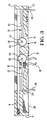
- an electrical connector is generally shown at 2 and a substrate card for insertion into the connector is generally shown at 4.
- the connector 2 is shown having a housing 6, a slot 8 profiled for receiving the card 4 at a front edge 11 of the connector 2, contacts 12 that project into the slot cavity 8 through contact cavities 14, a read-in contact 16, and a board lock feature 18 for mounting the connector 2 on a printed circuit board.
- the contacts 12 are shown having contact wheels 20 rotatably mounted to resilient arms 22.
- the resilient arm 22 is shown in the preferred embodiment to be a cantilever spring attached at a fixed end 23 to the housing 6 and the free end is an axle 25 bent into a central hole 24 in the wheel 20, such that the wheel can rotate thereabout.
- the resilient arms 22 are bent at their fixed ends 23 so that pins 28 project outwards of a base 26 of the housing 6, the base 26 being mounted substantially against a top surface 27 of the printed circuit board 1 shown in Figure 4, the pins 28 projecting into corresponding holes 30 of the printed circuit board 1.
- the pins 28 are electrically connected to the electrical circuit traces of the printed circuit board by soldering, in the preferred embodiment, although well known solderless connection methods such as press fit can also be used.
- the board lock feature 18 prevents the connector 2 from falling off the printed circuit board 1 during the assembly operations of the various electrical devices that are mounted to the printed circuit board 1.
- the resilient arm 22 of the preferred embodiment is formed from cylindrical wire which advantageously requires no particular preparation of the axle 25 which is advantageously round for smooth rotation of the wheel 20 therearound.
- the plurality of contacts 12 are disposed in two rows 17,19. This disposition not only reduces the width taken up for use by the contacts 12 to make electrical connection with the card 4, but also reduces the insertion force of the card 4 into the connector 2. Increased insertion force is required when the front edge of the card first touches the contacts 12 and lifts them onto the surface of the card against the resiliency of the resilient arms 22. By reducing the number of contacts that are simultaneously lifted by the front edge of the card during insertion, as with the preferred embodiment, one therefore reduces the insertion force thereof.
- the resilient arm 22 is provided quite long. In the preferred embodiment tight spacing of the two rows 17,19 of contacts is desired, one way of achieving this by disposing the contacts in an opposing manner due to the long resilient arms 22.
- Rolling of the contact wheels 20 reduces the wear of the card circuit traces and wheel contacting surfaces because there is no rubbing, but nevertheless maintaining a sufficient normal contact pressure between the contacts and the card circuit traces due to the resilient biasing of the resilient arms 22 that support the wheel 20. During extraction of the card from the slot 8 the contact wheels 20 roll thereoff, once again avoiding any rubbing action between the card 4 and connector contacts 12.
- Figure 4 shows the layout of the holes in the printed circuit board to which the preferred embodiment of this invention is mounted. Little holes 30 are to receive the contact pins 28 of the connector 2, and larger holes 29 are for the insertion of the board lock members 18 of the connector 2.
- the read-in contact 16 is shown and detects the presence of the card fully inserted into the connector slot 8.
- the read-in contact 16 is a long resilient cantilevered wire that projects into the slot of the connector 2 such that once the card 4 is partially inserted into the slot 8, the read-in contact 16 is biased up over the surface of the card and breaks (or establishes) electrical connection with a corresponding contact 15, thus making the presence or non-presence of the card 4 detectable.
- card connector 2 as described herein is only representative of the preferred embodiment of the invention and should not be limiting to the claimed invention. More specifically: The connector 2 could be electrically connected to electrical conducting cables and not mounted on a printed circuit board 1, the compactness and disposition of the contacts 12 could be varied, and the length and bent shape of the resilient arms 22 could also be varied.
Landscapes
- Engineering & Computer Science (AREA)
- Artificial Intelligence (AREA)
- Computer Vision & Pattern Recognition (AREA)
- Physics & Mathematics (AREA)
- General Physics & Mathematics (AREA)
- Theoretical Computer Science (AREA)
- Coupling Device And Connection With Printed Circuit (AREA)
- Details Of Connecting Devices For Male And Female Coupling (AREA)
Description
Claims (8)
- An electrical connector (2) for electrical connection between electrical circuit traces of a substrate card (4) and electrical circuit traces of a printed circuit board (1) or a conducting cable, the electrical connector (2) having a slot (8) profiled for receiving the card (4) therein, and contact means (28) for interconnection to the traces of the printed circuit board, wherein the contact means (28) are electrically connected to contact roller means (20) positioned proximate to said slot (8), whereby said contact roller means (20) can roll along said substrate card (4) during insertion thereof, into engagement with said traces on said substrate card, characterized in that, the contact roller means comprise a plurality of resilient electrical contacting members (12) having resilient arms (22) and rotatable contact wheels (20) mounted thereon.
- The connector of claim 1 characterized in that the wheels (20) project into the slot (8) when the card (4) is not therein, the wheels (20) are rotatable over the card (4) during inserion of the card (4) into the slot (8), and the wheels (20) are resiliently biased against the card circuit traces when the card (4) is fully inserted into the slot (8).
- The connector of claim 1 or 2 characterized in that the connector (2) has a base (26) mountable substantially against the printed circuit board (1), whereby the resilient arm (22) makes direct electrical contact between the wheel (20) and the printed circuit board circuit traces.
- The connector of any of claims 1 to 3 characterized in that the resilient arm (22) is a cantilevered beam whereby a fixed end (23) is attached to the connector (2), and to an axle end (25) is rotatably attached the wheel (20).
- The connector of claims 3 or 4 characterized in that the resilient arms (22) comprise pins (28) projecting from the base (26) and mountable thrcugh corresponding holes (30) in the printed circuit board (1) to make electrical contact therewith.
- The connector of any of claims 1-5 characterized in that the resilient arm (22) comprises only one piece including a pin (28) and an axle (25) to which the wheel (20) is rotatably attached.
- The connector of any of claims 1-5 characterized in that the resilient arm (22) is made from substantially cylindrically shaped wire.
- The connector of any of claims 1-7 characterized in that the contact means (20, 22) are disposed in two spaced apart mirror image rows.
Applications Claiming Priority (2)
| Application Number | Priority Date | Filing Date | Title |
|---|---|---|---|
| GB9306177 | 1993-03-25 | ||
| GB939306177A GB9306177D0 (en) | 1993-03-25 | 1993-03-25 | Smart card connector |
Publications (2)
| Publication Number | Publication Date |
|---|---|
| EP0617488A1 EP0617488A1 (en) | 1994-09-28 |
| EP0617488B1 true EP0617488B1 (en) | 1998-01-14 |
Family
ID=10732709
Family Applications (1)
| Application Number | Title | Priority Date | Filing Date |
|---|---|---|---|
| EP94104523A Expired - Lifetime EP0617488B1 (en) | 1993-03-25 | 1994-03-22 | Smart card connector |
Country Status (6)
| Country | Link |
|---|---|
| US (1) | US5470260A (en) |
| EP (1) | EP0617488B1 (en) |
| JP (1) | JPH06342680A (en) |
| KR (1) | KR100286566B1 (en) |
| DE (1) | DE69407844T2 (en) |
| GB (1) | GB9306177D0 (en) |
Cited By (2)
| Publication number | Priority date | Publication date | Assignee | Title |
|---|---|---|---|---|
| USD454875S1 (en) | 1999-12-29 | 2002-03-26 | Tyco Electronics Logistics Ag | Single smart card reader |
| USD456407S1 (en) | 1999-12-29 | 2002-04-30 | Tyco Electronics Logistics Ag | Stacked smart card reader |
Families Citing this family (25)
| Publication number | Priority date | Publication date | Assignee | Title |
|---|---|---|---|---|
| US5599203A (en) * | 1995-10-31 | 1997-02-04 | The Whitaker Corporation | Smart card and smart card connector |
| WO1998004994A1 (en) * | 1996-07-31 | 1998-02-05 | The Whitaker Corporation | Apparatus for making contact with a chip card |
| US5750973A (en) * | 1996-10-31 | 1998-05-12 | The Whitaker Corporation | Card reader |
| US6326568B2 (en) | 1997-07-02 | 2001-12-04 | Molex Incorporated | Blade switch assembly for a card reader |
| US6040705A (en) * | 1997-08-20 | 2000-03-21 | Electro Scientific Industries, Inc. | Rolling electrical contactor |
| US6491491B1 (en) | 1997-10-30 | 2002-12-10 | Sankyo Seiki Mfg. Co., Ltd. | Articulated robot |
| WO1999023731A1 (en) * | 1997-11-04 | 1999-05-14 | Electro Scientific Industries, Inc. | Multiple rolling contacts |
| USD420647S (en) * | 1998-07-31 | 2000-02-15 | Hon Hai Precision Ind. Co., Ltd. | Smart card connector |
| GB2341983B (en) * | 1998-09-24 | 2002-04-10 | Taiko Denki Co Ltd | Smart card interfaces |
| USD421421S (en) * | 1998-11-19 | 2000-03-07 | Honda Tsushin Kogyo Co., Ltd. | Connector receptacle for IC card |
| USD423455S (en) * | 1999-03-26 | 2000-04-25 | Mitsumi Electric Co., Ltd. | Electric connector |
| EP1073006A1 (en) * | 1999-07-26 | 2001-01-31 | Molex Incorporated | Chip card ejector system |
| USD449615S1 (en) | 1999-11-09 | 2001-10-23 | Schlumberger Systemes | Connector device for a smart card |
| US20080278903A1 (en) * | 2000-01-06 | 2008-11-13 | Super Talent Electronics, Inc. | Package and Manufacturing Method for Multi-Level Cell Multi-Media Card |
| DE60127468T2 (en) * | 2000-01-24 | 2008-01-31 | Nidec Sankyo Corp. | Manual chip card reader |
| US6508673B2 (en) | 2000-04-05 | 2003-01-21 | Mcdowell Jennifer Lyn | Low cost smart card reader, extension style, with wiping contacts |
| FR2809871B1 (en) * | 2000-06-05 | 2002-07-19 | Itt Mfg Entpr S Inc | ELECTRICAL CONNECTOR WITH IMPROVED CONTACT BLADES FOR CONNECTION OF AN INTEGRATED CIRCUIT (S) CARD |
| US6739881B2 (en) | 2001-05-31 | 2004-05-25 | Trw Inc. | High integration electronic assembly and method |
| JP3515084B2 (en) * | 2001-08-02 | 2004-04-05 | 日本圧着端子製造株式会社 | Hinge connector and circuit board connected to the connector |
| WO2006080070A1 (en) * | 2005-01-27 | 2006-08-03 | Fujitsu Limited | Electronic device |
| TWI351140B (en) * | 2006-10-30 | 2011-10-21 | Hon Hai Prec Ind Co Ltd | Electrical card connector |
| TWM315413U (en) * | 2006-11-20 | 2007-07-11 | Hon Hai Prec Ind Co Ltd | Electronical card connector |
| TW200824190A (en) * | 2006-11-20 | 2008-06-01 | Hon Hai Prec Ind Co Ltd | Electrical card connector |
| GB2452769B (en) * | 2007-09-17 | 2011-06-01 | Motorola Inc | Device and electrical contact mechanism therefor |
| US12444866B2 (en) * | 2019-03-14 | 2025-10-14 | Te Connectivity Solutions Gmbh Et Al. | Electrical connector system |
Family Cites Families (11)
| Publication number | Priority date | Publication date | Assignee | Title |
|---|---|---|---|---|
| FR2512595A1 (en) * | 1981-09-04 | 1983-03-11 | Cit Alcatel | MODULAR ELECTRICAL CONNECTION TERMINAL |
| JPS5936387A (en) * | 1982-08-25 | 1984-02-28 | Canon Inc | External memory unit attachment/detachment device |
| JPS6111284U (en) * | 1984-06-26 | 1986-01-23 | 沖電線株式会社 | Board connection connector |
| JPH0326628Y2 (en) * | 1986-06-24 | 1991-06-10 | ||
| JPH039267Y2 (en) * | 1986-12-27 | 1991-03-07 | ||
| FR2623313B1 (en) * | 1987-11-13 | 1991-10-04 | Cit Alcatel | CONTACT FRAME FOR CHIP CARD READER |
| JPH0233877A (en) * | 1988-07-21 | 1990-02-05 | Matsushita Electric Ind Co Ltd | IC card contact unit and IC card reading/writing device using the same |
| JPH03122982A (en) * | 1989-10-06 | 1991-05-24 | Mitsubishi Electric Corp | connector |
| JPH03190071A (en) * | 1989-12-20 | 1991-08-20 | Morimichi Fujiyoshi | Card employing equipment, manufacture of card connector and card connector |
| US5281148A (en) * | 1992-09-15 | 1994-01-25 | Trakker, Inc. | Electrical circuit card connector |
| US5321583A (en) * | 1992-12-02 | 1994-06-14 | Intel Corporation | Electrically conductive interposer and array package concept for interconnecting to a circuit board |
-
1993
- 1993-03-25 GB GB939306177A patent/GB9306177D0/en active Pending
-
1994
- 1994-03-15 US US08/213,418 patent/US5470260A/en not_active Expired - Fee Related
- 1994-03-22 EP EP94104523A patent/EP0617488B1/en not_active Expired - Lifetime
- 1994-03-22 DE DE69407844T patent/DE69407844T2/en not_active Expired - Fee Related
- 1994-03-23 KR KR1019940005800A patent/KR100286566B1/en not_active Expired - Fee Related
- 1994-03-25 JP JP6079838A patent/JPH06342680A/en active Pending
Cited By (2)
| Publication number | Priority date | Publication date | Assignee | Title |
|---|---|---|---|---|
| USD454875S1 (en) | 1999-12-29 | 2002-03-26 | Tyco Electronics Logistics Ag | Single smart card reader |
| USD456407S1 (en) | 1999-12-29 | 2002-04-30 | Tyco Electronics Logistics Ag | Stacked smart card reader |
Also Published As
| Publication number | Publication date |
|---|---|
| DE69407844T2 (en) | 1998-06-10 |
| DE69407844D1 (en) | 1998-02-19 |
| KR100286566B1 (en) | 2001-04-16 |
| KR940022954A (en) | 1994-10-22 |
| JPH06342680A (en) | 1994-12-13 |
| EP0617488A1 (en) | 1994-09-28 |
| US5470260A (en) | 1995-11-28 |
| GB9306177D0 (en) | 1993-05-19 |
Similar Documents
| Publication | Publication Date | Title |
|---|---|---|
| US5470260A (en) | Smart card connector | |
| EP0650230B1 (en) | Electrical connector having latch means | |
| US7371125B2 (en) | Miniature audio jack connector | |
| CA2252887C (en) | Miniature card docking connector | |
| US5277627A (en) | Electrical connector for IC card | |
| US5911597A (en) | Connector for flexible conductive line components | |
| EP0765004B1 (en) | Electrical installation bus connector | |
| US5472349A (en) | Surface mountable board edge connector | |
| EP0883855B1 (en) | Apparatus for the electrical connection of a chip card to a printed circuit board | |
| EP0140473B1 (en) | Solderless circuit board conductor and connector assemblies employing same | |
| US7758387B2 (en) | Electrical card connector with improved card restriction structure | |
| EP0542068B1 (en) | Female electrical contact | |
| US5820391A (en) | Miniature card interface connector | |
| US5009611A (en) | High density electrical connector for printed circuit boards | |
| EP1453143B1 (en) | Electrical connector having a holddown for ground connection | |
| WO1995035550A1 (en) | Sim card connector | |
| MY130144A (en) | Connector with press-fit terminal pins | |
| EP0554821A1 (en) | Smart card connector | |
| KR100288728B1 (en) | 3D electrical interconnection system | |
| EP0385019B1 (en) | Electrical connector having preloaded terminals and method of manufacture | |
| WO2001049718A3 (en) | Electrical connector with lock | |
| CN1076892C (en) | Smart card connector | |
| WO1998013905A1 (en) | Electronic module connector having a rotatable cover | |
| US5580267A (en) | Electrical connector for a printed circuit board | |
| US20240421531A1 (en) | Connector |
Legal Events
| Date | Code | Title | Description |
|---|---|---|---|
| PUAI | Public reference made under article 153(3) epc to a published international application that has entered the european phase |
Free format text: ORIGINAL CODE: 0009012 |
|
| AK | Designated contracting states |
Kind code of ref document: A1 Designated state(s): DE FR GB IT SE |
|
| 17P | Request for examination filed |
Effective date: 19950327 |
|
| 17Q | First examination report despatched |
Effective date: 19960708 |
|
| GRAG | Despatch of communication of intention to grant |
Free format text: ORIGINAL CODE: EPIDOS AGRA |
|
| GRAG | Despatch of communication of intention to grant |
Free format text: ORIGINAL CODE: EPIDOS AGRA |
|
| GRAH | Despatch of communication of intention to grant a patent |
Free format text: ORIGINAL CODE: EPIDOS IGRA |
|
| GRAH | Despatch of communication of intention to grant a patent |
Free format text: ORIGINAL CODE: EPIDOS IGRA |
|
| GRAA | (expected) grant |
Free format text: ORIGINAL CODE: 0009210 |
|
| AK | Designated contracting states |
Kind code of ref document: B1 Designated state(s): DE FR GB IT SE |
|
| PG25 | Lapsed in a contracting state [announced via postgrant information from national office to epo] |
Ref country code: IT Free format text: LAPSE BECAUSE OF FAILURE TO SUBMIT A TRANSLATION OF THE DESCRIPTION OR TO PAY THE FEE WITHIN THE PRESCRIBED TIME-LIMIT;WARNING: LAPSES OF ITALIAN PATENTS WITH EFFECTIVE DATE BEFORE 2007 MAY HAVE OCCURRED AT ANY TIME BEFORE 2007. THE CORRECT EFFECTIVE DATE MAY BE DIFFERENT FROM THE ONE RECORDED. Effective date: 19980114 |
|
| PGFP | Annual fee paid to national office [announced via postgrant information from national office to epo] |
Ref country code: SE Payment date: 19980205 Year of fee payment: 5 |
|
| REF | Corresponds to: |
Ref document number: 69407844 Country of ref document: DE Date of ref document: 19980219 |
|
| ET | Fr: translation filed | ||
| PG25 | Lapsed in a contracting state [announced via postgrant information from national office to epo] |
Ref country code: SE Free format text: LAPSE BECAUSE OF FAILURE TO SUBMIT A TRANSLATION OF THE DESCRIPTION OR TO PAY THE FEE WITHIN THE PRESCRIBED TIME-LIMIT Effective date: 19980414 |
|
| PLBE | No opposition filed within time limit |
Free format text: ORIGINAL CODE: 0009261 |
|
| STAA | Information on the status of an ep patent application or granted ep patent |
Free format text: STATUS: NO OPPOSITION FILED WITHIN TIME LIMIT |
|
| 26N | No opposition filed | ||
| PGFP | Annual fee paid to national office [announced via postgrant information from national office to epo] |
Ref country code: GB Payment date: 20010202 Year of fee payment: 8 |
|
| PGFP | Annual fee paid to national office [announced via postgrant information from national office to epo] |
Ref country code: FR Payment date: 20010301 Year of fee payment: 8 |
|
| REG | Reference to a national code |
Ref country code: GB Ref legal event code: IF02 |
|
| PG25 | Lapsed in a contracting state [announced via postgrant information from national office to epo] |
Ref country code: GB Free format text: LAPSE BECAUSE OF NON-PAYMENT OF DUE FEES Effective date: 20020322 |
|
| GBPC | Gb: european patent ceased through non-payment of renewal fee |
Effective date: 20020322 |
|
| PG25 | Lapsed in a contracting state [announced via postgrant information from national office to epo] |
Ref country code: FR Free format text: LAPSE BECAUSE OF NON-PAYMENT OF DUE FEES Effective date: 20021129 |
|
| REG | Reference to a national code |
Ref country code: FR Ref legal event code: ST |
|
| PGFP | Annual fee paid to national office [announced via postgrant information from national office to epo] |
Ref country code: DE Payment date: 20030331 Year of fee payment: 10 |
|
| PG25 | Lapsed in a contracting state [announced via postgrant information from national office to epo] |
Ref country code: DE Free format text: LAPSE BECAUSE OF NON-PAYMENT OF DUE FEES Effective date: 20041001 |