EP0617197B1 - A method for controlling the direction of a shield tunnelling machine and an apparatus therefor - Google Patents
A method for controlling the direction of a shield tunnelling machine and an apparatus therefor Download PDFInfo
- Publication number
- EP0617197B1 EP0617197B1 EP94301349A EP94301349A EP0617197B1 EP 0617197 B1 EP0617197 B1 EP 0617197B1 EP 94301349 A EP94301349 A EP 94301349A EP 94301349 A EP94301349 A EP 94301349A EP 0617197 B1 EP0617197 B1 EP 0617197B1
- Authority
- EP
- European Patent Office
- Prior art keywords
- screen
- spot
- light
- target
- tunneling machine
- Prior art date
- Legal status (The legal status is an assumption and is not a legal conclusion. Google has not performed a legal analysis and makes no representation as to the accuracy of the status listed.)
- Expired - Lifetime
Links
Images


Classifications
-
- E—FIXED CONSTRUCTIONS
- E21—EARTH OR ROCK DRILLING; MINING
- E21D—SHAFTS; TUNNELS; GALLERIES; LARGE UNDERGROUND CHAMBERS
- E21D9/00—Tunnels or galleries, with or without linings; Methods or apparatus for making thereof; Layout of tunnels or galleries
- E21D9/06—Making by using a driving shield, i.e. advanced by pushing means bearing against the already placed lining
- E21D9/093—Control of the driving shield, e.g. of the hydraulic advancing cylinders
-
- E—FIXED CONSTRUCTIONS
- E21—EARTH OR ROCK DRILLING; MINING
- E21D—SHAFTS; TUNNELS; GALLERIES; LARGE UNDERGROUND CHAMBERS
- E21D9/00—Tunnels or galleries, with or without linings; Methods or apparatus for making thereof; Layout of tunnels or galleries
- E21D9/003—Arrangement of measuring or indicating devices for use during driving of tunnels, e.g. for guiding machines
Definitions
- the present invention relates to a method of controlling the propelling direction of a shield tunneling machine used in the pipe-jacking process, and an apparatus therefor.
- the semi-shield process is applied for laying a conduit for sewerage or service water, wherein a shield tunneling machine is arranged, and the shield tunneling machine and Hume pipes following the shield tunneling machine are propelled by a pipe-jacking machine.
- beelining laser beam is sent along a scheduled line on which a conduit is to be laid, the shield tunneling machine and a plurality of pipes are propelled along the laser beam by the pipe-jacking machine, while the ground is excavated by the shield tunneling machine.
- the shield tunneling machine is provided with a target on which laser beam is projected, and with a television camera by which an image of the target is taken, and with a pointer wherein a forward end of the pointer is attached to a cutter head of the shield tunneling machine and a rear end of the pointer is disposed by the surface of the target.
- a target on which laser beam is projected and with a television camera by which an image of the target is taken, and with a pointer wherein a forward end of the pointer is attached to a cutter head of the shield tunneling machine and a rear end of the pointer is disposed by the surface of the target.
- a pointer wherein a forward end of the pointer is attached to a cutter head of the shield tunneling machine and a rear end of the pointer is disposed by the surface of the target.
- An image of laser spot projected on the target is taken by the television camera.
- the image of laser spot projected on the target is projected on a Braun tube and observed by an operator.
- a directional control means that is jacks are controlled so that the cutter head is turned against the tail shield by which the direction of the shield tunneling machine is adjusted according to the movement of the pointer which corresponds to the orientation of the cutter head and the tail shield and an angle between the cutter head and the tail shield.
- the target is mounted at a certain place in the shield tunneling machine.
- the shield tunneling machine is propelled by a pipe-jacking machine disposed in a start vertical shaft, while laser beam is sent from a laser beam source disposed in the start vertical shaft to the target.
- a spot of laser beam projected along the scheduled line on the target is made the origin on the target, and when the spot on the target, while the shield tunneling machine is projected, is displaced from the origin to the another place, it is found only that the section of shield tunneling machine is displaced from the scheduled line corresponding to the position of the spot of laser beam projected on the target, from an image of Braun tube.
- a shield tunneling machine in which laser beam is sent along a scheduled line to a target, which is pervious to light, and laser beam passing through the target is reflected by a reflector.
- the reflected laser beam by the reflector is projected on a screen, and the advanced direction of the shield tunneling machine can be controlled by observing a spot of laser beam projected on the target and a spot of laser beam projected on the screen.
- the shield tunneling machine the displacement of the spot of laser beam projected on the screen, while the shield tunneling machine is advanced, from the original spot of laser beam projected on the screen is detected by observing the screen, and the advanced direction of the shield tunneling machine is controlled corresponding to the detected displacement of spot of laser beam.
- the present invention provides a method of controlling the direction of shield tunneling machine having a cutter head provided with a cutter for excavating the ground, and with a tail shield connected through directional control means with the cutter head, the method comprises the steps : sending a beelining beam of light along the scheduled line for laying a conduit; projecting the beam of light on a target provided within the tail shield, thereafter reflecting the beam of light on a reflector provided on the cutter head and projecting the reflected beam of light to a screen provided with the tail shield; taking an image of the target and the screen by television camera; and when it is observed that a spot of beam of light projected on the screen is displaced from the original point to another point while the shield tunneling machine is propelled, controlling the directional control means so that the spot of beam of light projected on the screen is made to coincide with the original point.
- the present invention provides a directional control apparatus comprising: a cutter head provided with a cutter for excavating the ground and with a reflector for reflecting a beelining beam of light; a tail shield articulated through a directional control means with the cutter head, and provided with a target on which the beam of light is projected and which is pervious to the beam of light, with a screen on which the beam of light reflected by the reflector provided on the cutter is projected, and with a television camera for taking an image of the target and the screen; an image processor for processing the image taken by the television camera by which the position of the spot on the target and the screen is detected; a memory in which the position of the original spots of beam of light projected on the target and the screen, respectively, measured at the beginning of propelling shield tunneling machine is stored; a comparator in which a position of the present spot of beam of light projected on the screen during the propulsion of the shield tunneling machine is compared with the position of the original spot of beam of light projected on the
- spot of beelining beam of light for example, laser beam
- spot of beelining beam of light for example, laser beam
- the shield tunneling machine is deviated from the scheduled line while the shield tunneling machine is advanced, the displacement of the shield tunneling machine is accompanied by the spot of laser beam projected on the screen being displaced from the origin to another place. Therefore, when the displacement of the spot of beam of light projected on the screen from the origin to another place is detected, the propelling direction of the shield tunneling machine can be adjusted by operating the directional control means so that the spot of beam of light projected on the screen is made to coincide with the origin.
- the deviation of the shield tunneling machine from the scheduled line is accompanied by the spot of beam of light projected on the target and the spot of beam of light projected on the screen being displaced from the origin to another place on the target and the origin to another place on the screen, respectively.
- the direction of displacement of the spot of beam of light projected on the target from the origin to another place on the target and the direction of the displacement of the spot of beam of light projected on the screen from the origin to another place on the screen are opposite to the direction of the deviation of the shield tunneling machine from the scheduled line.
- the shield tunneling machine when the shield tunneling machine is deviated upward of the scheduled line, the spot of beam of light projected on the target and the spot of beam of light projected on the screen are moved downward of the origin on the target and the origin on the screen. Therefore, when the spot of beam of light projected on the target and the spot of beam of light projected on the screen are displaced from the origin to another place on the target and the origin to another place on the screen, respectively, with the propulsion of the shield tunneling machine, it can be found that the shield tunneling machine is advanced with being deviated from the scheduled line.
- the reflector When the cutter head is turned against the tail shield tunneling machine, the reflector is inclined in the opposite direction to the turning direction of the cutter head turned with turning the cutter head against the tail shield, so that the spot of beam projected on the screen is moved to approach the origin on the screen. Therefore, when the directional control means is operated in such a manner that the spot of beam of light projected on the screen is made to coincide with the origin on the screen, according to the operation of the directional guide means, the cutter head is turned against the tail shield, the front end of the cutter head is directed toward the scheduled line.
- the shield tunneling machine is directed to approach the scheduled line.
- the spot of beam of light projected on the target is moved to approach the origin on the target. Therefore, further, the directional control means are operated so that the spot of beam of light projected on the screen is made to coincide with the origin on the screen.
- the shield tunneling machine approaches slowly the scheduled line. By repeating the operation, the propelling direction can be adjusted to approach the scheduled line.
- the deviation can be automatically adjusted. Namely, laser beam sent in parallel with the scheduled line is projected on the target and passed through the target and the laser beam passed through the target is reflected toward the screen by the reflector and projected on the screen.
- the original points that is the origin on the target and the origin on the screen can be stored by the following method;
- the shield tunneling machine is disposed on the pipe-jacking machine in which the axis of the cutter head is coincides with the axis of the tail shield, and under the condition, laser beam is projected on the target and on the screen, an image of the target and the screen is taken by the television camera, the taken image is processed by the image processor, the positions of the spot of laser beam projected on the target and the spot of laser beam projected on the screen are processed are stored in the memory.
- an image of the target and the screen is continuously taken and the present position of spot of laser beam projected can be detected by taking continuously, further, by comparing the detected position with the origin on the screen by the comparator so that existence of the displacement of the spot of laser beam from the origin to another place, the direction of displacement thereof and the amount of displacement are detected, and signal can be generated according to the direction of displacement and the amount of displacement.
- the cutter head is turned against the tail shield so that the present spot of laser beam projected on the screen coincides with the origin on the screen, by which the front end of the cutter head can be adjusted to coincide with the scheduled line. Accordingly, under the condition, the shield tunneling machine is propelled and when the spot of laser beam projected on the screen is displaced from the origin to another place on the screen, the directional control means is operated so that the spot of laser beam projected on the screen coincides with the origin on the screen, by which the shield tunneling machine approaches the scheduled according to the propulsion of shield tunneling machine.
- shield tunneling machine A comprises a cutter head 1 arranged at the head in the advancing direction thereof (the left side in Fig. 1 ) and tail shield 2 (the right side in Fig. 1) following cutter head 1.
- Cutter head 1 is connected through two jacks 3a and 3b and one rod 4 with tail shield 2.
- the front end of tail shield 2 is engaged with the rear end of cutter head 1 so that cutter head 1 can be turned against tail shield 2 by actuating at the same time jacks 3a and 3b or by actuating selectively jack 3a or jack 3b.
- Cutter head 1 is formed with partition 1b, by which the inside of shield tunneling machine A is divided into a first area on the ground side and a second area on the interior side. Cutter is provided within the first area for excavating the ground.
- Motor 6 for driving cutter 5 mounted on cutter head 1 and reflector 7 are provided within the second area on the interior. Reflector 7 is secured to an end of arm 7a which other end is secured to partition 1b at a given distance from an axis 1a of cutter head 1.
- Cutter 5 is provided with a plurality of spokes 5a to which a plurality of bits 5b are secured.
- a reference point 8 into which shield tunneling machine A is controlled is set at the front end of cutter 5 on the axis 1a of cutter head 1, wherein a distance between reference point 8 and a turning point 1c on which cutter 5 is turned against tail shield 2 is set to a given amount L.
- beelining laser beam which goes straight is used, wherein the laser beam is sent along a scheduled line. Therefore, while shield tunneling machine A is advanced on the scheduled line, laser beam 9 is sent along the axis 2a of tail shield 2.
- Target 10 is provided within tail shield 2 on the axis 2a of tail shield 2 and behind reflector 7.
- Target 10 is secured to a stay 11 secured to an inner wall of tail shield 2.
- Reflector 7 is disposed at a distance from the axis 2a of tail shield 2 within tail shield 2.
- a pair of mirrors 12a, 12b are disposed between target 10 and reflector 7.
- Mirrors 12a, 12b are formed of reflectors by which laser beam is perfectly reflected.
- Mirror 12a is disposed on the axis 2a of tail shield 2 before target 10 and at an angle of 45 degrees with regard to the axis 2a of tail shield.
- Mirror 12b is opposed to mirror 12a and reflector 7, and at an angle of 45 degrees with regard to the axis 2a of tail shield 2 ahead of target 10 between target 10 and reflector 7.
- One-way mirror 13 is disposed at an angle 45 degrees with regard to the axis 2a of tail shield 2 between mirrors 12a, 12b. Screen 14 is opposed with one-way mirror 13.
- One-way mirror 13 transmits laser beam 9, which travels to reflector 7, and reflected light from reflector 7 is sent to screen 14, which is adjacent to target 10 and attached to stay 11.
- the size which is the distance of between reflector 7 and mirror 12b plus the distance between one-way mirror 13 and screen 14 is set to be 1/ 2 of the length L between reference point 8 of cutter head 1 and turning point 1c or more.
- Television camera 15 for taking an image of target 10 and screen 14 is provided at a given position within tail shield 2.
- Television camera 15 takes at the same time images of target 10 and screen 14, and image receiver 21 (mentioned hereinafter ) reads out the image.
- Directional control means for controlling the advancing direction of shield tunneling machine A by turning relatively cutter head 1 against tail shield 2, which is shown in Fig. 2, comprises two jacks 3a, 3b and one rod 4, which are arranged in the circumferential direction of shield tunneling machine A. with a distance.
- Jacks 3a and 3b are formed of hydraulic cylinders.
- Rod 4 is connected through pin and the like (not shown ) with cutter head 1, and connected through a pin and a universal joint with tail shield 2.
- cutter head 1 it is possible to turn cutter head 1 against tail shield 2 at a desired angle between cutter head 1 and tail shield 2 by extending and contracting jack 3a and / or jack 3b by supplying a desired amount of hydraulic oil to jack 3a and / or jack 3b.
- reference point 8 moves in a circle with radius which is a distance L between reference point 8 and turning point 1c on turning point 1c which is set on the axis 1a of cutter head 1.
- Actuating means for actuating jacks 3a, 3b comprise a hydraulic unit for generating hydraulic oil with a set pressure and hydraulic circuits for controlling a desired amount of hydraulic oil supplied to desired chambers of jack 3a and jack 3b, wherein the hydraulic circuits are conventional hydraulic circuits including directional cut off valve (not shown ), pilot check valve, relief valve and others.
- Image receiver 21 is composed of an image receiving part formed in the same manner as conventional television image receiver and a color separation part for separating a certain color, wherein the image of target 10 and screen 14 is displayed in the image receiving part, while color signal, for example, R signal in case where the color of laser beam is red, or G signal in case where the color of laser beam is green, is separated from the information of images (hereinafter it is called "laser spot") 10a, 14a of laser beam projected on target 10 and screen 14, which is transmitted to image processor 22.
- laser spot information of images
- image processor 22 coordinates of color signal, for example, R signal transmitted from image receiver 21 are operated, wherein the image processor is a conventional image processor.
- Image processor 22 is connected with image processing control unit 23 including memory, controlling circuit and other, wherein coordinates data of the original projected spots, that is, coordinate data of the origin on target O and the origin on screen o are gained from the information of images ( Fig. 4) on target 10 and screen 14 when beginning to propel shield tunneling machine A are stored in image processing unit 23 and coordinates data of the origin on target O, and the origin on screen o which are stored while propelling shield tunneling machine A are outputted from image processing unit 23 to comparator 24.
- a hold signal and a scene switching signal are periodically transmitted from image processing unit 23 to image processor 22.
- the information of images of target 10, and screen 14 are suitably changed according to the generation of the respective signals and held, and coordinates data of laser spots 10a, 14a when propelling shield tunneling machine are operated from the held image and operated data are transmitted to comparator 24.
- Coordinates data of the origin on target O and the origin screen o are transmitted from processing control unit 23 to comparator 24, and coordinate data of laser spots 10a, 14a while propelling shield tunneling machine A are transmitted from image processor 22 to comparator 24, wherein the respective data are compared with each other by which a direction and amount of displacement of laser spots 10a, 14a from the origin 0, 0 to another place and are detected so that whether shield tunneling machine A is deviated from a scheduled line (laser beam 9) or not is detected.
- operation signal is generated according to the displacements of laser spots 10a and 14a, and transmitted through interface 25 to actuator 26.
- Operation signal generated from comparator 24 is a signal for turning cutter head 1 against tail shield 2 so that laser spot 14a on screen 14 coincides with the origin on screen o, and a signal for selecting chambers of jack 3a and /or jack 3b and determining amount of hydraulic oil which is supplied to selected chambers.
- a hydraulic circuit (not shown ) is actuated according to transmitted operation signal by which a given amount of hydraulic oil is supplied to jacks 3a, 3b so that jacks 3a, 3b are moved with regard to tail shield 2.
- a tilted angle of reflector 7 is changed according to the movement of cutter head 1 against tail shield 2.
- Laser beam 9 is reflected on reflector 7 with an angle which is equal to two times as many as the change of angle of reflector 7, and projected through mirror 12b and one-way mirror 13 to screen 14.
- Laser spot 14a approaches the origin on screen o with the movement of cutter head 10 against tail shield 2.
- shield tunneling machine A is disposed on a pipe-jacking machine mounted in a start vertical shaft (not shown ) along the scheduled line.
- laser beam 9 is sent along a scheduled line from the rear of shield tunneling machine A, and projected on target 10 and on screen 14.
- the image taken by television camera 15 is processed by image processor 22, and the original projected spots are stored as the origin on target O and the origin on screen o in image processing control unit 23.
- the displacement of laser spots 10a, 14a from the origin on target O and the origin on screen o on target 10 and screen 14 is observed at intervals of time by image processor 22, image processing control unit 23 and comparator 24.
- operation signal is not generated immediately after laser spot 14a on screen 14 has been moved from the origin on screen o to another place.
- a certain buffer zone is provided between the displacement of laser spot 14a and the generation of operation signal. Therefore, in case where the displacement of laser spot 14 from the origin on screen o to another place is within the buffer zone, operation signal is not generated so that even if shield tunneling machine A shifts the scheduled line, the propelling direction is maintained.
- operation signal is transmitted from comparator 24 to actuator 26 so that jacks 3a, 3b are actuated at the same time or selectively according to the direction of turning cutter head 1 against tail shield 2. Namely, when shield tunneling machine A shifts above the scheduled line, hydraulic oil is supplied to jack 3a and jack 3b so that a rod of jack 3a is extended forward, while a rod of jack 3b is contracted.
- Cutter head 1 is directed downward toward the scheduled line according to the actuation of jacks 3a, 3b. With cutter head 1 turning against the tail shield 2, 3b, reflector 7 is tilted upward. Therefore, laser beam 9, which is projected on reflector 7, is reflected upward and travels through mirror 12b and one-way mirror 13 to screen 14 so that laser spot 14a on screen 14 approaches the origin on screen o, wherein laser spot 10a on target 10 is not changed.
- cutter head 1 If cutter head 1 is turned downward against tail shield 2 at the angle ⁇ between cutter head 1 and tail shield 2 corresponding to operation signal from comparator 24, reflector 7 is tilted upward at an angle of ⁇ . Accordingly, an angle between laser beam 9 projected on reflector 7 and the reflected light therefrom is 2 ⁇ . Since a distance between reflector 7 and screen 14 is set to be 1/2 of turning radius L of cutter head 1 (a distance between reference center 8 and turning center 1c), the displacement of reference center 8 when cutter head 1 is macroscopically equal to the displacement of spot 14a on screen 14.
- Reference point 8 is moved toward the scheduled line for Ltan ⁇ by turning cutter head 1 for an angle of ⁇ against tail shield 2.
- the moved distance Ltan ⁇ agrees with d which is the moved distance of shield tunneling machine A from the scheduled line. Therefore, when laser spot 14a on screen 14 coincides with the origin on screen o with cutter head 1 being turned against tail shield 2, reference point 8 of cutter head 1 coincides with the scheduled line.
- reference point 8 intersects with the scheduled line, while shield tunneling machine A approaches the scheduled line.
- Beam spot 10a on target 10 approaches the origin on target O and at the same time laser spot 14a on screen 14 is kept apart from the origin of screen o.
- cutter head 1 is turned against tail shield 2 in such a manner that laser spot 14a on screen 14 coincides with the origin of screen o, by which reference point 8 is made to coincide with the scheduled line so that the advanced direction of shield tunneling machine A can be controlled.
- a displacement of shield tunneling machine A can be determined by observing the displacement of laser spot projected on target, and the advanced direction of the shield tunneling machine can be controlled by controlling a directional control means so that laser spot projected on screen coincides with the origin on screen, when the displacement of a shield tunneling machine from the scheduled line is generated.
- the directional control apparatus of shield tunneling machine when shield tunneling machine deviated from a scheduled line while being propelled, an image of a target and a screen is taken by a television camera, and the image taken by television camera is processed by an image processor and laser spot on the target is compared with the origin on screen by which operation signal that executes to make laser spot on screen coincide with the origin on screen is generated and the operation signal is transmitted to an actuator for actuating the directional control means by which the advanced direction of shield tunneling machine can be controlled automatically so that the spot on screen is made to coincide with the origin on screen.
Landscapes
- Engineering & Computer Science (AREA)
- Mining & Mineral Resources (AREA)
- Environmental & Geological Engineering (AREA)
- Life Sciences & Earth Sciences (AREA)
- General Life Sciences & Earth Sciences (AREA)
- Geochemistry & Mineralogy (AREA)
- Geology (AREA)
- Excavating Of Shafts Or Tunnels (AREA)
Description
- The present invention relates to a method of controlling the propelling direction of a shield tunneling machine used in the pipe-jacking process, and an apparatus therefor.
- The semi-shield process is applied for laying a conduit for sewerage or service water, wherein a shield tunneling machine is arranged, and the shield tunneling machine and Hume pipes following the shield tunneling machine are propelled by a pipe-jacking machine. In the semi-shield process, beelining laser beam is sent along a scheduled line on which a conduit is to be laid, the shield tunneling machine and a plurality of pipes are propelled along the laser beam by the pipe-jacking machine, while the ground is excavated by the shield tunneling machine.
- When the shield tunneling machine is propelled, a variety of resistances are applied on the shield tunneling machine. Therefore, it happens that the propelling direction of the shield tunneling machine is deviated from the scheduled line. In order to control the propelling direction of the shield tunneling machine, the shield tunneling machine is provided with a target on which laser beam is projected, and with a television camera by which an image of the target is taken, and with a pointer wherein a forward end of the pointer is attached to a cutter head of the shield tunneling machine and a rear end of the pointer is disposed by the surface of the target. Such a machine is known from EP-A-0,466,348.
- An image of laser spot projected on the target is taken by the television camera. The image of laser spot projected on the target is projected on a Braun tube and observed by an operator. When it is checked that the projecting direction of the shield tunneling machine is deviated from the scheduled line, a directional control means, that is jacks are controlled so that the cutter head is turned against the tail shield by which the direction of the shield tunneling machine is adjusted according to the movement of the pointer which corresponds to the orientation of the cutter head and the tail shield and an angle between the cutter head and the tail shield.
- In the shield tunneling machine, the target is mounted at a certain place in the shield tunneling machine. The shield tunneling machine is propelled by a pipe-jacking machine disposed in a start vertical shaft, while laser beam is sent from a laser beam source disposed in the start vertical shaft to the target. A spot of laser beam projected along the scheduled line on the target is made the origin on the target, and when the spot on the target, while the shield tunneling machine is projected, is displaced from the origin to the another place, it is found only that the section of shield tunneling machine is displaced from the scheduled line corresponding to the position of the spot of laser beam projected on the target, from an image of Braun tube.
- Accordingly, from the observation of a spot of laser beam on the target which is displaced from one origin to another origin, it is difficult to find a control amount of the directional control means. Therefore, at present, the directional control of shield tunneling machine demands skill of an operator and his know-how.
- Recently, a shield tunneling machine is developed in which laser beam is sent along a scheduled line to a target, which is pervious to light, and laser beam passing through the target is reflected by a reflector. The reflected laser beam by the reflector is projected on a screen, and the advanced direction of the shield tunneling machine can be controlled by observing a spot of laser beam projected on the target and a spot of laser beam projected on the screen. In the shield tunneling machine, the displacement of the spot of laser beam projected on the screen, while the shield tunneling machine is advanced, from the original spot of laser beam projected on the screen is detected by observing the screen, and the advanced direction of the shield tunneling machine is controlled corresponding to the detected displacement of spot of laser beam.
- It is an object of the present invention to provide a method of controlling effectively and automatically the advanced direction of a shield tunneling machine.
- It is a second object of the present invention to provide a shield tunneling machine by which it is possible to adjust automatically the advanced direction of shield tunneling machine.
- In order to achieve the first object, the present invention provides a method of controlling the direction of shield tunneling machine having a cutter head provided with a cutter for excavating the ground, and with a tail shield connected through directional control means with the cutter head, the method comprises the steps : sending a beelining beam of light along the scheduled line for laying a conduit; projecting the beam of light on a target provided within the tail shield, thereafter reflecting the beam of light on a reflector provided on the cutter head and projecting the reflected beam of light to a screen provided with the tail shield; taking an image of the target and the screen by television camera; and when it is observed that a spot of beam of light projected on the screen is displaced from the original point to another point while the shield tunneling machine is propelled, controlling the directional control means so that the spot of beam of light projected on the screen is made to coincide with the original point.
- In order to achieve the second object of the present invention, the present invention provides a directional control apparatus comprising: a cutter head provided with a cutter for excavating the ground and with a reflector for reflecting a beelining beam of light; a tail shield articulated through a directional control means with the cutter head, and provided with a target on which the beam of light is projected and which is pervious to the beam of light, with a screen on which the beam of light reflected by the reflector provided on the cutter is projected, and with a television camera for taking an image of the target and the screen; an image processor for processing the image taken by the television camera by which the position of the spot on the target and the screen is detected; a memory in which the position of the original spots of beam of light projected on the target and the screen, respectively, measured at the beginning of propelling shield tunneling machine is stored; a comparator in which a position of the present spot of beam of light projected on the screen during the propulsion of the shield tunneling machine is compared with the position of the original spot of beam of light projected on the screen, and when it is detected that the present spot of beam of light projected on the screen is displaced from the original spot of beam of light to another place, signal corresponding to the displacement of the spot from the original spot to another place is generated; an actuator for actuating the directional control means by which the directional control means is operated so that the present spot of beam of light projected on the screen is made coincide with the original spot.
- According to the present invention, when beginning to propel the shield tunneling machine, spot of beelining beam of light, for example, laser beam, projected on the screen is defined as the origin on the screen. When the shield tunneling machine is deviated from the scheduled line while the shield tunneling machine is advanced, the displacement of the shield tunneling machine is accompanied by the spot of laser beam projected on the screen being displaced from the origin to another place. Therefore, when the displacement of the spot of beam of light projected on the screen from the origin to another place is detected, the propelling direction of the shield tunneling machine can be adjusted by operating the directional control means so that the spot of beam of light projected on the screen is made to coincide with the origin.
- When the shield tunneling machine is deviated from the scheduled line, the deviation of the shield tunneling machine from the scheduled line is accompanied by the spot of beam of light projected on the target and the spot of beam of light projected on the screen being displaced from the origin to another place on the target and the origin to another place on the screen, respectively. The direction of displacement of the spot of beam of light projected on the target from the origin to another place on the target and the direction of the displacement of the spot of beam of light projected on the screen from the origin to another place on the screen are opposite to the direction of the deviation of the shield tunneling machine from the scheduled line. Namely, when the shield tunneling machine is deviated upward of the scheduled line, the spot of beam of light projected on the target and the spot of beam of light projected on the screen are moved downward of the origin on the target and the origin on the screen. Therefore, when the spot of beam of light projected on the target and the spot of beam of light projected on the screen are displaced from the origin to another place on the target and the origin to another place on the screen, respectively, with the propulsion of the shield tunneling machine, it can be found that the shield tunneling machine is advanced with being deviated from the scheduled line.
- When the cutter head is turned against the tail shield tunneling machine, the reflector is inclined in the opposite direction to the turning direction of the cutter head turned with turning the cutter head against the tail shield, so that the spot of beam projected on the screen is moved to approach the origin on the screen. Therefore, when the directional control means is operated in such a manner that the spot of beam of light projected on the screen is made to coincide with the origin on the screen, according to the operation of the directional guide means, the cutter head is turned against the tail shield, the front end of the cutter head is directed toward the scheduled line.
- Therefore, the shield tunneling machine is directed to approach the scheduled line. With the shield tunneling machine approaching the scheduled line, the spot of beam of light projected on the target is moved to approach the origin on the target. Therefore, further, the directional control means are operated so that the spot of beam of light projected on the screen is made to coincide with the origin on the screen. When an angle between the cutter head and the tail shield is reduced, the shield tunneling machine approaches slowly the scheduled line. By repeating the operation, the propelling direction can be adjusted to approach the scheduled line.
- According to the above-mentioned directional control apparatus, when the shield tunneling machine is deviated from the scheduled line with the propulsion of the shield tunneling machine, the deviation can be automatically adjusted. Namely, laser beam sent in parallel with the scheduled line is projected on the target and passed through the target and the laser beam passed through the target is reflected toward the screen by the reflector and projected on the screen.
- Accordingly, the original points, that is the origin on the target and the origin on the screen can be stored by the following method; the shield tunneling machine is disposed on the pipe-jacking machine in which the axis of the cutter head is coincides with the axis of the tail shield, and under the condition, laser beam is projected on the target and on the screen, an image of the target and the screen is taken by the television camera, the taken image is processed by the image processor, the positions of the spot of laser beam projected on the target and the spot of laser beam projected on the screen are processed are stored in the memory.
- With the propulsion of the shield tunneling machine, an image of the target and the screen is continuously taken and the present position of spot of laser beam projected can be detected by taking continuously, further, by comparing the detected position with the origin on the screen by the comparator so that existence of the displacement of the spot of laser beam from the origin to another place, the direction of displacement thereof and the amount of displacement are detected, and signal can be generated according to the direction of displacement and the amount of displacement.
- Then, by operating the directional control means by the actuator according to signal outputted from the comparator, the cutter head is turned against the tail shield so that the present spot of laser beam projected on the screen coincides with the origin on the screen, by which the front end of the cutter head can be adjusted to coincide with the scheduled line. Accordingly, under the condition, the shield tunneling machine is propelled and when the spot of laser beam projected on the screen is displaced from the origin to another place on the screen, the directional control means is operated so that the spot of laser beam projected on the screen coincides with the origin on the screen, by which the shield tunneling machine approaches the scheduled according to the propulsion of shield tunneling machine.
- In the drawings,
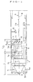
- Fig. 1 is a sectional view of a shield tunneling machine;
- Fig. 2 is a schematic illustration of a directional control means;
- Fig. 3 is a block diagram of a control system; and
- Fig. 4 is a schematic representation for showing an image of a target and a screen.
- Then, an embodiment of a directional control device and a method of controlling a direction of a shield tunneling machine are explained.
- Referring to Fig. 1, shield tunneling machine A comprises a cutter head 1 arranged at the head in the advancing direction thereof (the left side in Fig. 1 ) and tail shield 2 (the right side in Fig. 1) following cutter head 1. Cutter head 1 is connected through two
jacks rod 4 withtail shield 2. The front end oftail shield 2 is engaged with the rear end of cutter head 1 so that cutter head 1 can be turned againsttail shield 2 by actuating at thesame time jacks jack 3a orjack 3b. - Cutter head 1 is formed with
partition 1b, by which the inside of shield tunneling machine A is divided into a first area on the ground side and a second area on the interior side. Cutter is provided within the first area for excavating the ground. Motor 6 fordriving cutter 5 mounted on cutter head 1 andreflector 7 are provided within the second area on the interior.Reflector 7 is secured to an end ofarm 7a which other end is secured to partition 1b at a given distance from anaxis 1a of cutter head 1. -
Cutter 5 is provided with a plurality ofspokes 5a to which a plurality ofbits 5b are secured. Areference point 8 into which shield tunneling machine A is controlled is set at the front end ofcutter 5 on theaxis 1a of cutter head 1, wherein a distance betweenreference point 8 and a turning point 1c on whichcutter 5 is turned againsttail shield 2 is set to a given amount L. In the present embodiment, beelining laser beam which goes straight is used, wherein the laser beam is sent along a scheduled line. Therefore, while shield tunneling machine A is advanced on the scheduled line,laser beam 9 is sent along theaxis 2a oftail shield 2. -
Target 10 is provided withintail shield 2 on theaxis 2a oftail shield 2 and behindreflector 7.Target 10 is secured to astay 11 secured to an inner wall oftail shield 2.Reflector 7 is disposed at a distance from theaxis 2a oftail shield 2 withintail shield 2. In order to leadlaser beam 9 toreflector 7, a pair ofmirrors 12a, 12b are disposed betweentarget 10 andreflector 7. -
Mirrors 12a, 12b are formed of reflectors by which laser beam is perfectly reflected.Mirror 12a is disposed on theaxis 2a oftail shield 2 beforetarget 10 and at an angle of 45 degrees with regard to theaxis 2a of tail shield. Mirror 12b is opposed to mirror 12a andreflector 7, and at an angle of 45 degrees with regard to theaxis 2a oftail shield 2 ahead oftarget 10 betweentarget 10 andreflector 7. - One-
way mirror 13 is disposed at an angle 45 degrees with regard to theaxis 2a oftail shield 2 betweenmirrors 12a, 12b.Screen 14 is opposed with one-way mirror 13. One-way mirror 13 transmitslaser beam 9, which travels toreflector 7, and reflected light fromreflector 7 is sent to screen 14, which is adjacent to target 10 and attached to stay 11. - In the above-mentioned construction, the size which is the distance of between
reflector 7 and mirror 12b plus the distance between one-way mirror 13 andscreen 14 is set to be 1/ 2 of the length L betweenreference point 8 of cutter head 1 and turning point 1c or more. -
Television camera 15 for taking an image oftarget 10 andscreen 14 is provided at a given position withintail shield 2.Television camera 15 takes at the same time images oftarget 10 andscreen 14, and image receiver 21 (mentioned hereinafter ) reads out the image. - Directional control means for controlling the advancing direction of shield tunneling machine A by turning relatively cutter head 1 against
tail shield 2, which is shown in Fig. 2, comprises twojacks rod 4, which are arranged in the circumferential direction of shield tunneling machine A. with a distance.Jacks Rod 4 is connected through pin and the like (not shown ) with cutter head 1, and connected through a pin and a universal joint withtail shield 2. - Accordingly, it is possible to turn cutter head 1 against
tail shield 2 at a desired angle between cutter head 1 andtail shield 2 by extending andcontracting jack 3a and / orjack 3b by supplying a desired amount of hydraulic oil tojack 3a and / orjack 3b. With cutter head 1 turning againsttail shield 2,reference point 8 moves in a circle with radius which is a distance L betweenreference point 8 and turning point 1c on turning point 1c which is set on theaxis 1a of cutter head 1. - Actuating means for actuating
jacks jack 3a andjack 3b, wherein the hydraulic circuits are conventional hydraulic circuits including directional cut off valve ( not shown ), pilot check valve, relief valve and others. - Then, referring to Fig. 3, a control system of shield tunneling machine A is explained.
-
Television camera 15 is connected withimage receiver 21.Image receiver 21 is composed of an image receiving part formed in the same manner as conventional television image receiver and a color separation part for separating a certain color, wherein the image oftarget 10 andscreen 14 is displayed in the image receiving part, while color signal, for example, R signal in case where the color of laser beam is red, or G signal in case where the color of laser beam is green, is separated from the information of images (hereinafter it is called "laser spot") 10a, 14a of laser beam projected ontarget 10 andscreen 14, which is transmitted to imageprocessor 22. - In
image processor 22, coordinates of color signal, for example, R signal transmitted fromimage receiver 21 are operated, wherein the image processor is a conventional image processor.Image processor 22 is connected with imageprocessing control unit 23 including memory, controlling circuit and other, wherein coordinates data of the original projected spots, that is, coordinate data of the origin on target O and the origin on screen o are gained from the information of images ( Fig. 4) ontarget 10 andscreen 14 when beginning to propel shield tunneling machine A are stored inimage processing unit 23 and coordinates data of the origin on target O, and the origin on screen o which are stored while propelling shield tunneling machine A are outputted fromimage processing unit 23 tocomparator 24. - Further, after the propulsion of shield tunneling machine A has been begun, a hold signal and a scene switching signal are periodically transmitted from
image processing unit 23 to imageprocessor 22. The information of images oftarget 10, andscreen 14 are suitably changed according to the generation of the respective signals and held, and coordinates data oflaser spots comparator 24. - Coordinates data of the origin on target O and the origin screen o are transmitted from processing
control unit 23 tocomparator 24, and coordinate data oflaser spots image processor 22 tocomparator 24, wherein the respective data are compared with each other by which a direction and amount of displacement oflaser spots laser spots laser spots interface 25 toactuator 26. - Operation signal generated from
comparator 24 is a signal for turning cutter head 1 againsttail shield 2 so thatlaser spot 14a onscreen 14 coincides with the origin on screen o, and a signal for selecting chambers ofjack 3a and /orjack 3b and determining amount of hydraulic oil which is supplied to selected chambers. - In
actuator 26, a hydraulic circuit ( not shown ) is actuated according to transmitted operation signal by which a given amount of hydraulic oil is supplied tojacks jacks tail shield 2. A tilted angle ofreflector 7 is changed according to the movement of cutter head 1 againsttail shield 2.Laser beam 9 is reflected onreflector 7 with an angle which is equal to two times as many as the change of angle ofreflector 7, and projected through mirror 12b and one-way mirror 13 toscreen 14.Laser spot 14a approaches the origin on screen o with the movement ofcutter head 10 againsttail shield 2. - Then, a process of controlling a propelling direction of the above-mentioned shield tunneling machine A. First, shield tunneling machine A is disposed on a pipe-jacking machine mounted in a start vertical shaft ( not shown ) along the scheduled line. Then
laser beam 9 is sent along a scheduled line from the rear of shield tunneling machine A, and projected ontarget 10 and onscreen 14. The image taken bytelevision camera 15 is processed byimage processor 22, and the original projected spots are stored as the origin on target O and the origin on screen o in imageprocessing control unit 23. - Thereafter, the ground is excavated by
cutter 5, while shield tunneling machine A is propelled by the pipe-jacking machine. In the propelling process, if shield tunneling machine A shifts upward from the scheduled line while being propelled,laser beam 9 travels relatively downward with regard to theaxis 2a oftail shield 2 as shown by the dotted line in Fig. 1, whereinlaser spot 10a ontarget 10 andlaser spot 14a onscreen 14 are moved below the origin on target O and the origin on target o as shown in Fig. 4, respectively. Namely, a direction of displacement ofspots - The displacement of
laser spots target 10 andscreen 14 is observed at intervals of time byimage processor 22, imageprocessing control unit 23 andcomparator 24. In the present embodiment, immediately afterlaser spot 14a onscreen 14 has been moved from the origin on screen o to another place, operation signal is not generated. A certain buffer zone is provided between the displacement oflaser spot 14a and the generation of operation signal. Therefore, in case where the displacement oflaser spot 14 from the origin on screen o to another place is within the buffer zone, operation signal is not generated so that even if shield tunneling machine A shifts the scheduled line, the propelling direction is maintained. - In case where
laser spot 14a onscreen 14 is moved beyond the buffer zone from the origin on screen o to another place, operation signal is transmitted fromcomparator 24 toactuator 26 so thatjacks tail shield 2. Namely, when shield tunneling machine A shifts above the scheduled line, hydraulic oil is supplied tojack 3a andjack 3b so that a rod ofjack 3a is extended forward, while a rod ofjack 3b is contracted. - Cutter head 1 is directed downward toward the scheduled line according to the actuation of
jacks tail shield reflector 7 is tilted upward. Therefore,laser beam 9, which is projected onreflector 7, is reflected upward and travels through mirror 12b and one-way mirror 13 to screen 14 so thatlaser spot 14a onscreen 14 approaches the origin on screen o, whereinlaser spot 10a ontarget 10 is not changed. - If cutter head 1 is turned downward against
tail shield 2 at the angle θ between cutter head 1 andtail shield 2 corresponding to operation signal fromcomparator 24,reflector 7 is tilted upward at an angle of θ. Accordingly, an angle betweenlaser beam 9 projected onreflector 7 and the reflected light therefrom is 2θ . Since a distance betweenreflector 7 andscreen 14 is set to be 1/2 of turning radius L of cutter head 1 (a distance betweenreference center 8 and turning center 1c), the displacement ofreference center 8 when cutter head 1 is macroscopically equal to the displacement ofspot 14a onscreen 14. - Namely, when shield tunneling machine A deviates at a distance d from a scheduled line,
laser spot 10a ontarget 10, andlaser spot 14a onscreen 14 are moved at the distance d from the origin on target O and the origin on screen o, respectively. Assuming thatlaser spot 14a onscreen 14 coincides with the origin on screen o, when cutter head 1 is turned for an angle of θ against tail shield, equation : d = L tan 2θ/2 exists. Since tan 2θ=2tan θ/(1-tan2θ), when θ is an extremely small amount, it may be justifiable that tan2θ= 0 Therefore, tan 2θ=2tan θ ,and d=Ltan θ. -
Reference point 8 is moved toward the scheduled line for Ltan θ by turning cutter head 1 for an angle of θ againsttail shield 2. The moved distance Ltan θ agrees with d which is the moved distance of shield tunneling machine A from the scheduled line. Therefore, whenlaser spot 14a onscreen 14 coincides with the origin on screen o with cutter head 1 being turned againsttail shield 2,reference point 8 of cutter head 1 coincides with the scheduled line. - When shield tunneling machine A is advanced with an angle of cutter head 1 against
tail shield 2 being maintained,reference point 8 intersects with the scheduled line, while shield tunneling machine A approaches the scheduled line. With shield tunneling machine A approaching the scheduled line,Beam spot 10a ontarget 10 approaches the origin on target O and at the sametime laser spot 14a onscreen 14 is kept apart from the origin of screen o. - In the above-mentioned process, image processing for image taken by
television camera 15 is continued, and in case wherelaser spot 14a onscreen 14 is within the buffer zone, operation signal is not outputted fromcomparator 24 toactuator 26. - As above-mentioned, when shield tunneling machine A deviates from the scheduled line, cutter head 1 is turned against
tail shield 2 in such a manner thatlaser spot 14a onscreen 14 coincides with the origin of screen o, by whichreference point 8 is made to coincide with the scheduled line so that the advanced direction of shield tunneling machine A can be controlled. - As explained in detail hereinbefore, according to the present invention, a displacement of shield tunneling machine A can be determined by observing the displacement of laser spot projected on target, and the advanced direction of the shield tunneling machine can be controlled by controlling a directional control means so that laser spot projected on screen coincides with the origin on screen, when the displacement of a shield tunneling machine from the scheduled line is generated.
- By the directional control apparatus of shield tunneling machine according to the present invention, when shield tunneling machine deviated from a scheduled line while being propelled, an image of a target and a screen is taken by a television camera, and the image taken by television camera is processed by an image processor and laser spot on the target is compared with the origin on screen by which operation signal that executes to make laser spot on screen coincide with the origin on screen is generated and the operation signal is transmitted to an actuator for actuating the directional control means by which the advanced direction of shield tunneling machine can be controlled automatically so that the spot on screen is made to coincide with the origin on screen.
Claims (4)
- A method of controlling the direction of a shield tunneling machine having a cutter head (1) provided with a cutter for excavating the ground, and with a tail shield connected through directional control means (3a, 3b) with the cutter head, comprising the steps of:sending a beelining beam of light along the scheduled line for laying a conduit;projecting the beam of light on a target (10) provided within the tail shield, thereafter reflecting the beam of light on a reflector (7) provided on the cutter head and projecting the reflected beam of light to a screen (14) provided with the tail shield;taking an image of the target and the screen by a television camera (15); andwhen it is observed that a spot of beam of light (14a) projected on the screen is displaced from the original point to another place while the shield tunneling machine is propelled, controlling the directional control means so that the spot of beam of light projected on the screen is made to coincide with the original point.
- A directional control apparatus for a shield tunneling machine comprising:a cutter head (1) provided with a cutter for excavating the ground and with a reflector (7) for reflecting a beelining beam of light;a tail shield (2) articulated through a directional control means (3a, 3b) with the cutter head, and provided with a target (10) on which the beam of light is adapted to be projected and which is pervious to the beam of light, with a screen (14) on which the beam of light reflected by the reflector provided on the cutter is projected, and with a television camera (15) for taking an image of the target and the screen;an image processor (22) for processing the image taken by the television camera by which the position of the spot of beam of light on the target (10a) and the screen (14a) is detected;a memory in which the position of the original spots of beam of light projected on the target and the screen, respectively, measured at the beginning of propelling shield tunneling machine is stored;a comparator (24) in which a position of the present spot of beam of light projected on the screen during the propulsion of the shield tunneling machine is compared with the position of the original spot of beam of light projected on the screen, and when it is detected that the present spot of beam of light projected on the screen is displaced from the original spot to another place of beam of light, a signal corresponding to the displacement of the present spot from the original spot to another place is generated;an actuator (26) for actuating the directional control means by which the directional control means is operated so that the present spot of beam of light projected on the screen is made to coincide with the original spot.
- A directional control apparatus as claimed in claim 2 wherein the beelining beam of light is a laser beam.
- A directional control apparatus as claimed in claim 2 wherein the directional control means are jacks.
Applications Claiming Priority (2)
| Application Number | Priority Date | Filing Date | Title |
|---|---|---|---|
| JP85111/93 | 1993-03-22 | ||
| JP5085111A JP2968904B2 (en) | 1993-03-22 | 1993-03-22 | Excavator direction corrector |
Publications (2)
| Publication Number | Publication Date |
|---|---|
| EP0617197A1 EP0617197A1 (en) | 1994-09-28 |
| EP0617197B1 true EP0617197B1 (en) | 1997-05-21 |
Family
ID=13849521
Family Applications (1)
| Application Number | Title | Priority Date | Filing Date |
|---|---|---|---|
| EP94301349A Expired - Lifetime EP0617197B1 (en) | 1993-03-22 | 1994-02-25 | A method for controlling the direction of a shield tunnelling machine and an apparatus therefor |
Country Status (5)
| Country | Link |
|---|---|
| US (1) | US5501548A (en) |
| EP (1) | EP0617197B1 (en) |
| JP (1) | JP2968904B2 (en) |
| KR (1) | KR100240889B1 (en) |
| DE (1) | DE69403255T2 (en) |
Families Citing this family (22)
| Publication number | Priority date | Publication date | Assignee | Title |
|---|---|---|---|---|
| US6203111B1 (en) * | 1999-10-29 | 2001-03-20 | Mark Ollis | Miner guidance using laser and image analysis |
| AU2002953110A0 (en) * | 2002-12-05 | 2002-12-19 | Rod Davies Infrastructure Pty. Ltd. | Boring machine |
| USD497395S1 (en) | 2003-04-30 | 2004-10-19 | R.F.E. International Limited | Game control device |
| KR100537613B1 (en) * | 2003-06-20 | 2005-12-19 | 삼성에스디아이 주식회사 | Anode composition of lithium battery, and anode and lithium battery employing the same |
| US7651170B2 (en) * | 2003-07-18 | 2010-01-26 | Rodney John Davies | Bore head for microbore operation |
| KR100522698B1 (en) * | 2003-10-01 | 2005-10-19 | 삼성에스디아이 주식회사 | Carboxymethylcellulose based binder material and Lithium battery using the same |
| EP2035645B1 (en) * | 2006-06-16 | 2014-10-15 | Vermeer Manufacturing Company | Microtunnelling system and apparatus |
| US20080073121A1 (en) * | 2006-09-27 | 2008-03-27 | Jason Austin Cartwright | Laser Control System and Apparatus for Drilling and Boring Operations |
| US11590606B2 (en) * | 2008-08-20 | 2023-02-28 | Foro Energy, Inc. | High power laser tunneling mining and construction equipment and methods of use |
| US8256536B2 (en) * | 2009-02-11 | 2012-09-04 | Vermeer Manufacturing Company | Backreamer for a tunneling apparatus |
| US20120051843A1 (en) * | 2010-08-27 | 2012-03-01 | King Abdul Aziz City For Science And Technology | Tunnel drilling machine |
| US9587491B2 (en) | 2010-09-22 | 2017-03-07 | Joy Mm Delaware, Inc. | Guidance system for a mining machine |
| DE112011103169T5 (en) | 2010-09-22 | 2013-07-11 | Joy Mm Delaware, Inc. | Guidance system for a mining machine |
| CN103343689B (en) * | 2013-07-21 | 2015-03-11 | 中核华泰建设有限公司 | Full-functional slurry balance push pipe |
| US9946263B2 (en) * | 2013-12-19 | 2018-04-17 | Aktiebolaget Electrolux | Prioritizing cleaning areas |
| CN106814756B (en) * | 2015-12-02 | 2020-06-23 | 王傳宗 | Direction guiding controller for propelling machine |
| CN108111577A (en) * | 2017-12-04 | 2018-06-01 | 广州轨道交通建设监理有限公司 | Shield collecting method, device and computer readable storage medium |
| CN108930678A (en) * | 2018-08-16 | 2018-12-04 | 安徽卓科智能装备有限公司 | A kind of push-bench four-point deviation-rectifying system |
| US11085295B2 (en) * | 2019-01-24 | 2021-08-10 | Huaneng Tibet Yarlungzangbo River Hydropower Development Investment Co., Ltd. | Tunnel boring robot and remote mobile terminal command system |
| CN110306988A (en) * | 2019-07-02 | 2019-10-08 | 重庆市能源投资集团科技有限责任公司 | A kind of deflection deviation correction control system of shield machine |
| CN111648777A (en) * | 2020-05-25 | 2020-09-11 | 中铁四院集团岩土工程有限责任公司 | Horizontal deviation correction method of shield tunnel |
| KR102517032B1 (en) * | 2020-11-09 | 2023-04-03 | 한국남동발전 주식회사 | The improved safety management device, system of shield TBM tunnel construction segment assembly work and safety management method thereof |
Family Cites Families (8)
| Publication number | Priority date | Publication date | Assignee | Title |
|---|---|---|---|---|
| JPS55142897A (en) * | 1979-04-21 | 1980-11-07 | Iseki Kaihatsu Koki | Pipe driver |
| JP2606872B2 (en) * | 1988-03-14 | 1997-05-07 | 石川島播磨重工業株式会社 | Attitude control method of tunnel machine |
| JPH0739992Y2 (en) * | 1988-05-16 | 1995-09-13 | 株式会社小松製作所 | Articulated shield machine |
| JP2934896B2 (en) * | 1990-03-09 | 1999-08-16 | 株式会社小松製作所 | Apparatus and method for calculating backfill injection amount in shield method |
| JPH07103781B2 (en) * | 1990-04-19 | 1995-11-08 | 株式会社小松製作所 | How to operate a small diameter underground machine |
| JP2623157B2 (en) * | 1990-07-13 | 1997-06-25 | 株式会社イセキ開発工機 | Control device for moving objects |
| JP2566497B2 (en) * | 1991-07-19 | 1996-12-25 | 株式会社イセキ開発工機 | Method and apparatus for controlling direction of excavator |
| JPH0544392A (en) * | 1991-08-12 | 1993-02-23 | Iseki Tory Tech Inc | Excavator |
-
1993
- 1993-03-22 JP JP5085111A patent/JP2968904B2/en not_active Expired - Fee Related
-
1994
- 1994-02-22 KR KR1019940003084A patent/KR100240889B1/en not_active Expired - Fee Related
- 1994-02-24 US US08/201,332 patent/US5501548A/en not_active Expired - Fee Related
- 1994-02-25 EP EP94301349A patent/EP0617197B1/en not_active Expired - Lifetime
- 1994-02-25 DE DE69403255T patent/DE69403255T2/en not_active Expired - Fee Related
Also Published As
| Publication number | Publication date |
|---|---|
| KR100240889B1 (en) | 2000-01-15 |
| DE69403255T2 (en) | 1997-11-27 |
| US5501548A (en) | 1996-03-26 |
| JPH06272485A (en) | 1994-09-27 |
| EP0617197A1 (en) | 1994-09-28 |
| KR940021889A (en) | 1994-10-19 |
| JP2968904B2 (en) | 1999-11-02 |
| DE69403255D1 (en) | 1997-06-26 |
Similar Documents
| Publication | Publication Date | Title |
|---|---|---|
| US5501548A (en) | Method for controlling the direction of a shield tunneling machine and an apparatus therefor | |
| US5530330A (en) | Automated guidance system for a vehicle | |
| EP1278917B1 (en) | Laser-guided construction equipment | |
| EP0523907B1 (en) | Method and apparatus for controlling direction of excavating machine | |
| KR101084025B1 (en) | Parking Assistance, Vehicle-side Device of Parking Assistance, Parking Assistance Method and Parking Assistance Program | |
| EP3702539A1 (en) | Alarm device for construction machinery | |
| EP3899680B1 (en) | Method and device for determining the position of a mining and/or construction machine | |
| AU652763B2 (en) | A method and system for controlling a travelling body so as to move forward along the predetermined route of the movement of travelling body | |
| EP4407103A1 (en) | Work machine control system, and work machine | |
| CN114165257B (en) | Automatic segment assembling method and system for shield tunneling machine | |
| EP0449581B1 (en) | Shield tunnelling apparatus | |
| JP3024910B2 (en) | Automatic excavation control equipment for excavating construction machinery | |
| JPH06258077A (en) | Automatic excavating system | |
| JP2022056312A (en) | Existing pipe regeneration position measurement system and method | |
| JPH09219811A (en) | Camera direction control device for remote control machine | |
| JPH0510721A (en) | Target distance correction method, target, distance correction device, and excavation device using the distance correction device | |
| JPH06214640A (en) | Travel controller for mobile object | |
| CN216901412U (en) | Automatic assembling system for shield machine pipe sheets | |
| JP2942109B2 (en) | How to excavate a tunnel excavator | |
| JP2771353B2 (en) | Beam light tracking device for work vehicle guidance | |
| JPH1193220A (en) | Remote control device for construction machine | |
| WO2025122040A1 (en) | Method and system for autonomously operating a mining and/or construction machine | |
| JPH0544391A (en) | Excavator guidance method | |
| JPH0678308A (en) | Method for securing visual field of unattended truck | |
| JP2793388B2 (en) | Excavator direction control method and apparatus |
Legal Events
| Date | Code | Title | Description |
|---|---|---|---|
| PUAI | Public reference made under article 153(3) epc to a published international application that has entered the european phase |
Free format text: ORIGINAL CODE: 0009012 |
|
| AK | Designated contracting states |
Kind code of ref document: A1 Designated state(s): DE FR GB |
|
| 17P | Request for examination filed |
Effective date: 19940829 |
|
| GRAG | Despatch of communication of intention to grant |
Free format text: ORIGINAL CODE: EPIDOS AGRA |
|
| 17Q | First examination report despatched |
Effective date: 19960912 |
|
| GRAH | Despatch of communication of intention to grant a patent |
Free format text: ORIGINAL CODE: EPIDOS IGRA |
|
| GRAH | Despatch of communication of intention to grant a patent |
Free format text: ORIGINAL CODE: EPIDOS IGRA |
|
| GRAA | (expected) grant |
Free format text: ORIGINAL CODE: 0009210 |
|
| AK | Designated contracting states |
Kind code of ref document: B1 Designated state(s): DE FR GB |
|
| REF | Corresponds to: |
Ref document number: 69403255 Country of ref document: DE Date of ref document: 19970626 |
|
| ET | Fr: translation filed | ||
| PLBE | No opposition filed within time limit |
Free format text: ORIGINAL CODE: 0009261 |
|
| STAA | Information on the status of an ep patent application or granted ep patent |
Free format text: STATUS: NO OPPOSITION FILED WITHIN TIME LIMIT |
|
| 26N | No opposition filed | ||
| REG | Reference to a national code |
Ref country code: GB Ref legal event code: IF02 |
|
| PGFP | Annual fee paid to national office [announced via postgrant information from national office to epo] |
Ref country code: FR Payment date: 20020212 Year of fee payment: 9 |
|
| PGFP | Annual fee paid to national office [announced via postgrant information from national office to epo] |
Ref country code: GB Payment date: 20020227 Year of fee payment: 9 |
|
| PGFP | Annual fee paid to national office [announced via postgrant information from national office to epo] |
Ref country code: DE Payment date: 20020314 Year of fee payment: 9 |
|
| PG25 | Lapsed in a contracting state [announced via postgrant information from national office to epo] |
Ref country code: GB Free format text: LAPSE BECAUSE OF NON-PAYMENT OF DUE FEES Effective date: 20030225 |
|
| PG25 | Lapsed in a contracting state [announced via postgrant information from national office to epo] |
Ref country code: DE Free format text: LAPSE BECAUSE OF NON-PAYMENT OF DUE FEES Effective date: 20030902 |
|
| GBPC | Gb: european patent ceased through non-payment of renewal fee | ||
| PG25 | Lapsed in a contracting state [announced via postgrant information from national office to epo] |
Ref country code: FR Free format text: LAPSE BECAUSE OF NON-PAYMENT OF DUE FEES Effective date: 20031031 |
|
| REG | Reference to a national code |
Ref country code: FR Ref legal event code: ST |