EP0616657B1 - Vehicle control console having finger tip controls - Google Patents
Vehicle control console having finger tip controls Download PDFInfo
- Publication number
- EP0616657B1 EP0616657B1 EP93922158A EP93922158A EP0616657B1 EP 0616657 B1 EP0616657 B1 EP 0616657B1 EP 93922158 A EP93922158 A EP 93922158A EP 93922158 A EP93922158 A EP 93922158A EP 0616657 B1 EP0616657 B1 EP 0616657B1
- Authority
- EP
- European Patent Office
- Prior art keywords
- pair
- vehicle
- operator
- handrest
- levers
- Prior art date
- Legal status (The legal status is an assumption and is not a legal conclusion. Google has not performed a legal analysis and makes no representation as to the accuracy of the status listed.)
- Expired - Lifetime
Links
- 210000003813 thumb Anatomy 0.000 claims abstract description 6
- 230000007246 mechanism Effects 0.000 claims description 34
- 230000033001 locomotion Effects 0.000 claims description 28
- 230000005540 biological transmission Effects 0.000 claims description 18
- 230000002441 reversible effect Effects 0.000 claims description 12
- 230000008859 change Effects 0.000 claims description 11
- 230000004044 response Effects 0.000 claims description 9
- 230000000994 depressogenic effect Effects 0.000 claims 1
- 210000003811 finger Anatomy 0.000 abstract description 5
- 238000010276 construction Methods 0.000 abstract description 3
- 230000000881 depressing effect Effects 0.000 description 4
- 210000000245 forearm Anatomy 0.000 description 2
- 230000000712 assembly Effects 0.000 description 1
- 238000000429 assembly Methods 0.000 description 1
- 230000007423 decrease Effects 0.000 description 1
- 239000012530 fluid Substances 0.000 description 1
- 230000007935 neutral effect Effects 0.000 description 1
Images
Classifications
-
- G—PHYSICS
- G05—CONTROLLING; REGULATING
- G05G—CONTROL DEVICES OR SYSTEMS INSOFAR AS CHARACTERISED BY MECHANICAL FEATURES ONLY
- G05G1/00—Controlling members, e.g. knobs or handles; Assemblies or arrangements thereof; Indicating position of controlling members
- G05G1/01—Arrangements of two or more controlling members with respect to one another
-
- B—PERFORMING OPERATIONS; TRANSPORTING
- B60—VEHICLES IN GENERAL
- B60N—SEATS SPECIALLY ADAPTED FOR VEHICLES; VEHICLE PASSENGER ACCOMMODATION NOT OTHERWISE PROVIDED FOR
- B60N2/00—Seats specially adapted for vehicles; Arrangement or mounting of seats in vehicles
- B60N2/75—Arm-rests
- B60N2/79—Adaptations for additional use of the arm-rests
- B60N2/797—Adaptations for additional use of the arm-rests for use as electrical control means, e.g. switches
-
- E—FIXED CONSTRUCTIONS
- E02—HYDRAULIC ENGINEERING; FOUNDATIONS; SOIL SHIFTING
- E02F—DREDGING; SOIL-SHIFTING
- E02F9/00—Component parts of dredgers or soil-shifting machines, not restricted to one of the kinds covered by groups E02F3/00 - E02F7/00
- E02F9/20—Drives; Control devices
- E02F9/2004—Control mechanisms, e.g. control levers
-
- G—PHYSICS
- G05—CONTROLLING; REGULATING
- G05G—CONTROL DEVICES OR SYSTEMS INSOFAR AS CHARACTERISED BY MECHANICAL FEATURES ONLY
- G05G1/00—Controlling members, e.g. knobs or handles; Assemblies or arrangements thereof; Indicating position of controlling members
- G05G1/58—Rests or guides for relevant parts of the operator's body
- G05G1/62—Arm rests
-
- G—PHYSICS
- G05—CONTROLLING; REGULATING
- G05G—CONTROL DEVICES OR SYSTEMS INSOFAR AS CHARACTERISED BY MECHANICAL FEATURES ONLY
- G05G13/00—Manually-actuated control mechanisms provided with two or more controlling members and also two or more controlled members
-
- Y—GENERAL TAGGING OF NEW TECHNOLOGICAL DEVELOPMENTS; GENERAL TAGGING OF CROSS-SECTIONAL TECHNOLOGIES SPANNING OVER SEVERAL SECTIONS OF THE IPC; TECHNICAL SUBJECTS COVERED BY FORMER USPC CROSS-REFERENCE ART COLLECTIONS [XRACs] AND DIGESTS
- Y10—TECHNICAL SUBJECTS COVERED BY FORMER USPC
- Y10T—TECHNICAL SUBJECTS COVERED BY FORMER US CLASSIFICATION
- Y10T74/00—Machine element or mechanism
- Y10T74/20—Control lever and linkage systems
- Y10T74/20012—Multiple controlled elements
-
- Y—GENERAL TAGGING OF NEW TECHNOLOGICAL DEVELOPMENTS; GENERAL TAGGING OF CROSS-SECTIONAL TECHNOLOGIES SPANNING OVER SEVERAL SECTIONS OF THE IPC; TECHNICAL SUBJECTS COVERED BY FORMER USPC CROSS-REFERENCE ART COLLECTIONS [XRACs] AND DIGESTS
- Y10—TECHNICAL SUBJECTS COVERED BY FORMER USPC
- Y10T—TECHNICAL SUBJECTS COVERED BY FORMER US CLASSIFICATION
- Y10T74/00—Machine element or mechanism
- Y10T74/20—Control lever and linkage systems
- Y10T74/20396—Hand operated
-
- Y—GENERAL TAGGING OF NEW TECHNOLOGICAL DEVELOPMENTS; GENERAL TAGGING OF CROSS-SECTIONAL TECHNOLOGIES SPANNING OVER SEVERAL SECTIONS OF THE IPC; TECHNICAL SUBJECTS COVERED BY FORMER USPC CROSS-REFERENCE ART COLLECTIONS [XRACs] AND DIGESTS
- Y10—TECHNICAL SUBJECTS COVERED BY FORMER USPC
- Y10T—TECHNICAL SUBJECTS COVERED BY FORMER US CLASSIFICATION
- Y10T74/00—Machine element or mechanism
- Y10T74/20—Control lever and linkage systems
- Y10T74/20576—Elements
- Y10T74/20582—Levers
- Y10T74/20612—Hand
Definitions
- This invention relates generally to an earthworking vehicle having a control console with various operating functions and more particularly to a control console assembly and the orientation of the control functions with respect to an operator.
- control consoles have been available for construction equipment. Many of these control console utilize one or more levers which an operator grasps and moves in order to control the operating functions of the construction vehicle. These levers may be moved fore and aft, sideways or various combinations thereof, such as, a joy stick control which is well known in the art.
- the known controls are capable of providing precise control of the respective vehicle operating functions.
- the operator due to the jostling of the machine as it traverses over rough terrain, the operator is being likewise jostled within the vehicle. Consequently, since the operator is being jostled around in the vehicle, his arm is likewise being moved with his body which tends to offset precise control of the lever or levers located on the control console.
- a console was provided which allowed the operator to control some of the vehicle's operating functions by the operator's fingers moving electrical switches between an on and off position. Even though the operator's hand was laying on a control console and his fingertips were controlling electrical switches, the operator was not gaining precise control of the operating function. This is true because his hand could still easily move with respect to the control console due to the movement of his body, thus, possibly causing loss of contact of his fingertips with the respective switches.
- the present invention is directed to overcoming one or more of the problems as set forth above.
- US-A-3 703 931 discloses a vehicle control mechanism for use by an operator to control an earthworking vehicle having multiple operating functions, the vehicle control mechanism comprising a control console assembly oriented, in use, adjacent one side of the operator and having, connected thereto, a handrest with a top surface; a pair of levers pivotally mounted on the control console assembly and located adjacent the handrest, each of the levers being disposed such as to be movable, in use, by any one of the operator's fingertips; a pair of sensors, each being operative, in use, to deliver an electrical signal to control one of the vehicle's operating functions.
- a vehicle control mechanism for use by an operator to control an earthworking vehicle having multiple operating functions, characterised by
- the present invention provides a vehicle control mechanism that allows the operator's hand to be maintained in a steady position even though his body is being jostled within the vehicle from the vehicle being traversed over a rough terrain. Since the operating functions of the vehicle is controlled by the operator's fingertips, a more precise control of the electrical signal inputs to the microprocessor is maintained. Consequently, the control of the vehicle and the vehicle's operating functions are more smoothly maintained.
- a seat 10 of an earthworking vehicle (not shown) is generally diagrammatically illustrated.
- the earthworking vehicle has various multiple operating functions and includes a reversible multi-speed transmission 12 and a steering control mechanism 14.
- the reversible multi-speed transmission 12 includes forward and reverse clutches 16,18 and multiple speed ratio clutches 20,22,24.
- Each of the forward and reverse and speed clutches 16,18 being electrically controlled in response to receipt of an electrical signal.
- the electrical signal is directed to an electro-hydraulic valve mechanism which in turn directs a hydraulic fluid signal to actuate the respective clutches.
- the steering control mechanism 14 includes steer clutches 26,28 and brakes 30,32.
- the steer clutches 26,28 are located on opposite sides of the earthworking vehicle to drive, when engaged, the outputs on each side of the earthworking vehicle.
- the steer brakes are located on each side of the vehicle and are operative, when applied, to stop the outputs on each side thereof.
- Each of the steer clutches 26,28 and brakes 30,32 are actuated by electrically controlled proportional valves 34.
- Each of the electrically controlled proportional valves 34 are operational to control the respective drive clutches 26,28 and the brakes 30,32 in response to receipt of an electrical signal thereto.
- the steer clutches 26,28 and/or brakes 30,32 can be progressively activated or deactivated depending on the electrical signal provided thereto.
- a microprocessor 36 is provided to deliver electrical signals to operate the various operating functions through electrical signal connections 38,40,42,44,46,48,50,52,54.
- a vehicle control mechanism 60 is provided and is located on the earthworking vehicle adjacent the operator's seat 10. Even though the vehicle control mechanism 60 is illustrated as being mounted on the vehicle, it is recognized that the vehicle control mechanism 60 could be connected to the operator's seat 10 without departing from the essence of the invention.
- the vehicle control mechanism 60 includes a frame member 64 and a control console assembly 66 adjustably connected to the frame member 64.
- An electrically controlled actuator 68 is connected to the frame 64 and the control console assembly 66 and is operative to raise and lower the control console assembly 66 relative to the frame member 64.
- the control console assembly 66 has an armrest 70 mounted thereon.
- the armrest 70 has a top surface 72 oriented generally along a horizontal plane 74 defined thereon.
- the top surface 72 of the armrest 70 generally lies with the length thereof parallel to the travel path of the earthworking vehicle. However, it is recognized, that the length of the armrest 70 could lie in a line that is not parallel with the path of the earthworking vehicle without departing from the essence of the invention.
- a handrest 76 is located on the control console assembly 66 and positioned adjacent the armrest 70 at one end thereof.
- the handrest 76 has a top surface 77 oriented along the perpendicular plane 74 and a raised portion 78 located thereon.
- the raised portion 78 of the handrest 76 is oriented above the top surface 72 of the armrest 70 so that the palm of the operator's hand can lay over the handrest 76 and the heel of the operator's hand can be firmly supported against the raised portion.
- the raised portion 78 of the handrest 76 has an angle of inclination with respect to the horizontal plane 74 in the range of 5 to 9 degrees. As is illustrated in Figure 4, the angle of inclination is at 7 degrees.
- the raised portion 78 of the handrest 76 is oriented generally perpendicular to the travel path of the vehicle. However it is recognized, that the position of the raised portion 78 could be at various angles with respect to the travel path of the vehicle without departing from the essence of the invention.
- the most elevated portion of the raised portion 78 is located on the side thereof generally adjacent the operator so that the operator's hand can rest thereon in the most normal and relaxed condition.
- a rotary shaft 84 is disposed in the handrest 76 on the side thereof adjacent the operator and extends therein along a path generally parallel the angle of inclination of the raised portion 78.
- the rotary shaft 84 is rotatably secured to the control console assembly 76 so that it can be rotated in a clockwise or counter clockwise direction.
- a knob 86 is secured to the end of the rotary shaft 84 adjacent the end thereof adjacent the operator.
- a pair of depressions 88,90 are defined on the knob 86, each being spaced from the other. The pair of depressions 88,90 are oriented on the knob 86 so that the thumb of the operator's hand can easily be located within each of the pair of depressions to rotate the rotary shaft 84 in the clockwise or counter clockwise direction.
- An electrical switch such as a three-position electrical switch 92, is mounted on the control console assembly 66 and operatively connected to the rotary shaft 84 by a mechanical linkage 93 and operative to deliver an electrical signal therefrom in response to clockwise or counter clockwise rotation of the rotary shaft 84.
- the electrical signal from the three-position electrical switch 92 is delivered to the microprocessor 36 by an electrical connection 94.
- a pair of electrical push button switches 96,98 are mounted on the knob 86 adjacent the pair of depressions 88,90 so that the operator's thumb can easily depress either of the pair of electrical push buttons switches 96,98.
- An electrical signal is transmitted from the respective ones of the pair of electrical push button switches 96,98 to the microprocessor 36 by electrical connections 100,102.
- An electrical actuator switch 104 is located on the side of the control console assembly 66 adjacent the operator and operative to readily allow the operator to raise or lower the control console assembly 66 relative to the frame 64.
- a pair of levers 106,108 is pivotally mounted on the control console assembly 66 adjacent the handrest 76 and oriented on the side thereof opposite the armrest 70 and positioned such that the operator's fingertips are accessible thereto.
- a pair of rotary sensors 112,114 are mounted on the control console assembly 66 and are operative to deliver electrical signals in response to rotary input thereto.
- the electrical signals delivered therefrom are delivered to the microprocessor 36 through electrical connections 116,118.
- a pair of linkage mechanism 120,122 are operative to connect the respective ones of the pair of levers 106,108 to respective ones of the pair of rotary sensors 112,114. Even though, in the arrangement illustrated, the pair of linkage mechanisms 120,122 is utilized to interconnect the pair of levers 106,108 to the respective pair of rotary sensors 112,114, it is recognized that the pair of levers 106,108 could be connected directly to the respective ones of the pair of rotary sensors 112,114 without departing from the essence of the invention.
- a pair of tension springs 124,126 is connected to respective ones of the pair of linkage mechanisms 120,122 and operative to provide extra force to movement of the respective ones of the pair of levers 106,108 once each has been moved through approximately one half of its travel distance.
- a rotary sensor could be utilized to replace the three-position electrical switch 92 without departing from the essence of the invention.
- various forms of the vehicle control mechanism could be utilized to control various other combinations of vehicle operating functions, such as, bulldozer blades, ripper assemblies, operating functions of loaders, operating functions of excavators, etc.
- the operator rests his forearm on the armrest 70 and the palm of his hand on the handrest 76. It is recognized, that the operator may elect not to place his forearm on the armrest 70 and only rest the palm of his hand on the handrest 76. In either situation, the heal of the operator's hand is in constant, intimate contact with the raised portion 78 of the handrest 76. Even though the operator is being jostled about due to the earthworking vehicle traversing rough terrain, the operator's hand remains in intimate contact with the raised portion 78 of the handrest 76.
- the operator places his thumb in one of the pair of depressions 88,90 and rotates the knob 86 and, consequently, the rotary shaft 84 in a clockwise direction.
- the clockwise movement of the knob 86 moves the three-position electrical switch 92 to one of its operative positions thus directing an electrical signal through the electrical connection 100 to the microprocessor 36.
- the microprocessor 36 Upon receipt of the input signal from the three-position electrical switch 92, the microprocessor 36 delivers a signal through the electrical connection 46 to the forward clutch 16 of the multi-speed transmission 12. This electrical signal activates the forward clutch 16 resulting in the earthworking vehicle moving in a forward direction.
- the operator depresses one of the pair of electrical push button switches 96,98 which delivers an electrical signal to the microprocessor 36 through the electrical connection 100.
- the microprocessor 36 Upon receipt of the input signal the electrical connection 100, the microprocessor 36 the microprocessor 36 terminates the electrical signal to the speed clutch 20 and simultaneously delivers another electrical signal through the electrical connection 52 to the speed clutch 22 thus changing the speed of the transmission to a second higher speed.
- the multi-speed transmission 12 is shifted from the second higher speed to yet a third higher speed.
- the extra pressing of the one of the pair of electrical push buttons switches 96,98 directs the input signal through the electrical connection 100 to the microprocessor 36.
- the microprocessor 36 Upon receipt of the electrical signal produced by depression of the one of the pair of electrical push button switches 96,98, the microprocessor 36 terminates the electrical signal to the speed clutch 22 and transmit an electrical signal through the conduit 54 to the third speed clutch 34 thus changing the multi-speed transmission 12 to its third operating speed.
- the operator desires to change the speed of the multi-speed transmission 12 from its third operating speed back to the second operating speed, the operator merely depresses the other one of the pair of electrical push button switches 96,98 to send an electrical signal to the microprocessor 36 which, in turn, terminate the electrical signal to the speed clutch 24 and transmits an electrical signal to activate the speed clutch 22 thus changing the multi-speed transmission 12 from its third operating speed to its second operating speed.
- the multi-speed transmission 12 changes from its second operating speed to its first operating speed in a similar manner by the microprocessor 36 terminating the electrical signal to the speed clutch 22 and transmitting an electrical signal to the speed clutch 20.
- the operator places his thumb in the other one of the pair of depression 88,90 and rotates the knob 86 in a counter clockwise direction.
- the counter clockwise movement of the knob 86 moves the three-position electrical switch 92 from its first operative position back to its neutral position and progressively to its other operative position.
- an electrical signal is directed through the electrical connection 94 to the microprocessor 36 which in turn terminates the electrical signal to the forward clutch 16 and transmits an electrical signal to activate the reverse clutch 18.
- the reverse speed of the multi-speed transmission 12 is increased by the operator depressing the one of the pair of electrical push button switches 96,98 thus increasing the reverse travel speed.
- the reverse speed of the earthworking vehicle can be reduced by the operator depressing the other one of the pair of electrical push button switches 96,98.
- the operator In order to steer or change the angle of travel direction, the operator merely uses his fingertips to move respective ones of the pair of levers 106,108. For a minor change in the angle of travel direction, the operator uses the tip of one of his fingers to move one of the pair of levers 106,108 towards the handrest 76. Movement of the one of the pair of levers 106,108 towards the handrest 76 simultaneously rotates one of the pair of rotary sensors 112,114. During rotary motion of the one of the pair of rotary sensors 112,114, an electrical signal is transmitted through electrical connection 116 to the microprocessor 36. As is well known, the energy of the electrical signal increases or decreases with each increment of rotation of the respective rotary sensor 112,114.
- the microprocessor 36 transmits an electrical signal through the electrical connection 38 to the electrically controlled proportional valve 34 of the steer clutch 26 to cause the steer clutch 26 to slip. This allows the earthworking vehicle to change its angle of travel in a conventional manner, as is well known in the art. For every increment of movement of the one of the pair of levers 106,108 towards the handrest 76, the speed clutch 26 is progressively disengaged to provide a greater angle of change to the vehicle travel direction.
- the steer clutch 26 is fully disengaged. Further movement of the one of the pair of levers 106,108 towards the handrest 76 continues to change the electrical signal being transmitted to the microprocessor 36. The further movement of the one of the pair of levers 106,108 is detected by the operator since the respective one of the pair of tension springs 124,126 adds additional force to movement of the one of the pair of levers 106,108.
- the microprocessor 36 reacting to the continued increase in the electrical signal from the one of the pair of rotary sensors 112,114 maintains the steer clutch 26 in its fully released condition and transmits a signal through electrical connection 40 to the electrically controlled proportion valve 34 of the steer brake 30. This signal progressively applies the steer brake 30 resulting in a more rapid change in the angle of travel of the earthworking vehicle. Once the one of the pair of levers 106,108 is moved to its extreme position by the operator's fingertip, the steer brake 30 is fully applied and the rotational output on the one side of the earthworking vehicle is stopped.
- the heel of the operator's hand remains in intimate contact with the raised portion 78 of the handrest 76 thus providing more finite control of the one of the pair of levers 106,108. This remains true even though the operator is being jostled around on the seat due to the earthworking vehicle traversing rough terrain. In order to change the angle of travel of the earthworking vehicle to a different direction, the operator merely uses the tip of one of his fingers to progressively move the other of the pair of levers 106,108 towards the handrest 76 as set forth above with respect to movement of the one of the pair of levers 106,108.
- an electrical signal is transmitted from the other of the pair of rotary sensors 112,114 through the electrical connection 118 to the microprocessor 36.
- the microprocessor 36 Upon receipt of the input signal from the other of the pair of rotary sensors 112,114, the microprocessor 36 transmits an electrical signal through the electrical connection 44 to the electrically controlled proportional valve 34 of the steer clutch 28. This electrical signal progressively disengages the steer clutch 28 responsive to the degree of movement of the other of the pair of levers 106,108. Once the other of the pair of levers 106,108 is moved through approximately half of its range of travel, the steer clutch 28 is fully disengaged.
- the operator presses the electrical actuator switch 104 to either raise or lower the control console 66 relative to the frame 64. Once the armrest 70 and the handrest 76 are in the position desired, the operator merely releases the electrical actuator switch 104 and the control console assembly 66 remains in the desired position.
Landscapes
- Engineering & Computer Science (AREA)
- Physics & Mathematics (AREA)
- Automation & Control Theory (AREA)
- General Physics & Mathematics (AREA)
- Aviation & Aerospace Engineering (AREA)
- Structural Engineering (AREA)
- General Engineering & Computer Science (AREA)
- Civil Engineering (AREA)
- Mining & Mineral Resources (AREA)
- Transportation (AREA)
- Mechanical Engineering (AREA)
- Mechanical Control Devices (AREA)
- Operation Control Of Excavators (AREA)
- Component Parts Of Construction Machinery (AREA)
- Arrangement Or Mounting Of Control Devices For Change-Speed Gearing (AREA)
- Vehicle Step Arrangements And Article Storage (AREA)
- Non-Deflectable Wheels, Steering Of Trailers, Or Other Steering (AREA)
Abstract
Description
- This invention relates generally to an earthworking vehicle having a control console with various operating functions and more particularly to a control console assembly and the orientation of the control functions with respect to an operator.
- Various types of control consoles have been available for construction equipment. Many of these control console utilize one or more levers which an operator grasps and moves in order to control the operating functions of the construction vehicle. These levers may be moved fore and aft, sideways or various combinations thereof, such as, a joy stick control which is well known in the art. The known controls are capable of providing precise control of the respective vehicle operating functions. However, due to the jostling of the machine as it traverses over rough terrain, the operator is being likewise jostled within the vehicle. Consequently, since the operator is being jostled around in the vehicle, his arm is likewise being moved with his body which tends to offset precise control of the lever or levers located on the control console. This jostling movement of the operator within the cab of the vehicle is even more pronounced when operating track type vehicles. In one arrangement, a console was provided which allowed the operator to control some of the vehicle's operating functions by the operator's fingers moving electrical switches between an on and off position. Even though the operator's hand was laying on a control console and his fingertips were controlling electrical switches, the operator was not gaining precise control of the operating function. This is true because his hand could still easily move with respect to the control console due to the movement of his body, thus, possibly causing loss of contact of his fingertips with the respective switches.
- The present invention is directed to overcoming one or more of the problems as set forth above.
- US-A-3 703 931 discloses a vehicle control mechanism for use by an operator to control an earthworking vehicle having multiple operating functions, the vehicle control mechanism comprising a control console assembly oriented, in use, adjacent one side of the operator and having, connected thereto, a handrest with a top surface; a pair of levers pivotally mounted on the control console assembly and located adjacent the handrest, each of the levers being disposed such as to be movable, in use, by any one of the operator's fingertips; a pair of sensors, each being operative, in use, to deliver an electrical signal to control one of the vehicle's operating functions.
- According to the present invention there is provided a vehicle control mechanism for use by an operator to control an earthworking vehicle having multiple operating functions, characterised by
- the handrest having a horizontal plane defined along the top surface, and a raised portion adapted for the operator to rest the palm of his hand on, in use, and to provide firm support for the heel of his hand, the raised portion of the handrest being inclined with respect to the horizontal plane at an angle in the range of five to nine degrees; and
- a pair of rotary sensors mounted on the control console assembly, each being connected to a respective one of the levers and being operative, on rotation thereof in use, to provide a signal in response to movement of the respective lever.
- The present invention provides a vehicle control mechanism that allows the operator's hand to be maintained in a steady position even though his body is being jostled within the vehicle from the vehicle being traversed over a rough terrain. Since the operating functions of the vehicle is controlled by the operator's fingertips, a more precise control of the electrical signal inputs to the microprocessor is maintained. Consequently, the control of the vehicle and the vehicle's operating functions are more smoothly maintained.
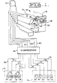
- Figure 1 is a diagrammatic representation of an embodiment of the present invention including a vehicle control mechanism;
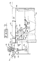
- Figure 2 is a partial side view of the vehicle control mechanism of Figure 1;
- Figure 3 is an opposite side view of the vehicle control mechanism of Figure 1; and
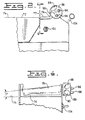
- Figure 4 is a partial end view of the vehicle control mechanism of Figure 1.
- Referring to the drawings, a
seat 10 of an earthworking vehicle (not shown) is generally diagrammatically illustrated. The earthworking vehicle has various multiple operating functions and includes a reversiblemulti-speed transmission 12 and asteering control mechanism 14. The reversiblemulti-speed transmission 12 includes forward andreverse clutches speed ratio clutches speed clutches - The
steering control mechanism 14 includessteer clutches brakes steer clutches steer clutches brakes proportional valves 34. Each of the electrically controlledproportional valves 34 are operational to control therespective drive clutches brakes proportional valves 34, thesteer clutches brakes microprocessor 36 is provided to deliver electrical signals to operate the various operating functions throughelectrical signal connections - A
vehicle control mechanism 60 is provided and is located on the earthworking vehicle adjacent the operator'sseat 10. Even though thevehicle control mechanism 60 is illustrated as being mounted on the vehicle, it is recognized that thevehicle control mechanism 60 could be connected to the operator'sseat 10 without departing from the essence of the invention. Thevehicle control mechanism 60 includes aframe member 64 and acontrol console assembly 66 adjustably connected to theframe member 64. An electrically controlledactuator 68 is connected to theframe 64 and thecontrol console assembly 66 and is operative to raise and lower thecontrol console assembly 66 relative to theframe member 64. - The
control console assembly 66 has anarmrest 70 mounted thereon. Thearmrest 70 has atop surface 72 oriented generally along ahorizontal plane 74 defined thereon. Thetop surface 72 of thearmrest 70 generally lies with the length thereof parallel to the travel path of the earthworking vehicle. However, it is recognized, that the length of thearmrest 70 could lie in a line that is not parallel with the path of the earthworking vehicle without departing from the essence of the invention. - A
handrest 76 is located on thecontrol console assembly 66 and positioned adjacent thearmrest 70 at one end thereof. Thehandrest 76 has atop surface 77 oriented along theperpendicular plane 74 and a raisedportion 78 located thereon. The raisedportion 78 of thehandrest 76 is oriented above thetop surface 72 of thearmrest 70 so that the palm of the operator's hand can lay over thehandrest 76 and the heel of the operator's hand can be firmly supported against the raised portion. The raisedportion 78 of thehandrest 76 has an angle of inclination with respect to thehorizontal plane 74 in the range of 5 to 9 degrees. As is illustrated in Figure 4, the angle of inclination is at 7 degrees. Furthermore, the raisedportion 78 of thehandrest 76 is oriented generally perpendicular to the travel path of the vehicle. However it is recognized, that the position of the raisedportion 78 could be at various angles with respect to the travel path of the vehicle without departing from the essence of the invention. The most elevated portion of the raisedportion 78 is located on the side thereof generally adjacent the operator so that the operator's hand can rest thereon in the most normal and relaxed condition. - A
rotary shaft 84 is disposed in thehandrest 76 on the side thereof adjacent the operator and extends therein along a path generally parallel the angle of inclination of the raisedportion 78. Therotary shaft 84 is rotatably secured to thecontrol console assembly 76 so that it can be rotated in a clockwise or counter clockwise direction. Aknob 86 is secured to the end of therotary shaft 84 adjacent the end thereof adjacent the operator. A pair ofdepressions knob 86, each being spaced from the other. The pair ofdepressions knob 86 so that the thumb of the operator's hand can easily be located within each of the pair of depressions to rotate therotary shaft 84 in the clockwise or counter clockwise direction. - An electrical switch, such as a three-position
electrical switch 92, is mounted on thecontrol console assembly 66 and operatively connected to therotary shaft 84 by amechanical linkage 93 and operative to deliver an electrical signal therefrom in response to clockwise or counter clockwise rotation of therotary shaft 84. The electrical signal from the three-positionelectrical switch 92 is delivered to themicroprocessor 36 by anelectrical connection 94. - A pair of electrical
push button switches knob 86 adjacent the pair ofdepressions push button switches microprocessor 36 by electrical connections 100,102. - An
electrical actuator switch 104 is located on the side of thecontrol console assembly 66 adjacent the operator and operative to readily allow the operator to raise or lower thecontrol console assembly 66 relative to theframe 64. - A pair of levers 106,108 is pivotally mounted on the
control console assembly 66 adjacent thehandrest 76 and oriented on the side thereof opposite thearmrest 70 and positioned such that the operator's fingertips are accessible thereto. - A pair of rotary sensors 112,114 are mounted on the
control console assembly 66 and are operative to deliver electrical signals in response to rotary input thereto. The electrical signals delivered therefrom are delivered to themicroprocessor 36 through electrical connections 116,118. - A pair of linkage mechanism 120,122 are operative to connect the respective ones of the pair of levers 106,108 to respective ones of the pair of rotary sensors 112,114. Even though, in the arrangement illustrated, the pair of linkage mechanisms 120,122 is utilized to interconnect the pair of levers 106,108 to the respective pair of rotary sensors 112,114, it is recognized that the pair of levers 106,108 could be connected directly to the respective ones of the pair of rotary sensors 112,114 without departing from the essence of the invention. A pair of tension springs 124,126 is connected to respective ones of the pair of linkage mechanisms 120,122 and operative to provide extra force to movement of the respective ones of the pair of levers 106,108 once each has been moved through approximately one half of its travel distance.
- It is recognized that a rotary sensor could be utilized to replace the three-position
electrical switch 92 without departing from the essence of the invention. Furthermore, even though the earthworking vehicle described herein is for the control of a transmission and steering clutches and brakes, it is recognized that various forms of the vehicle control mechanism could be utilized to control various other combinations of vehicle operating functions, such as, bulldozer blades, ripper assemblies, operating functions of loaders, operating functions of excavators, etc. - During operation of the earthworking vehicle described herein, the operator rests his forearm on the
armrest 70 and the palm of his hand on thehandrest 76. It is recognized, that the operator may elect not to place his forearm on thearmrest 70 and only rest the palm of his hand on thehandrest 76. In either situation, the heal of the operator's hand is in constant, intimate contact with the raisedportion 78 of thehandrest 76. Even though the operator is being jostled about due to the earthworking vehicle traversing rough terrain, the operator's hand remains in intimate contact with the raisedportion 78 of thehandrest 76. - In order to shift the
multi-speed transmission 12 into a forward direction, the operator places his thumb in one of the pair ofdepressions knob 86 and, consequently, therotary shaft 84 in a clockwise direction. The clockwise movement of theknob 86 moves the three-positionelectrical switch 92 to one of its operative positions thus directing an electrical signal through theelectrical connection 100 to themicroprocessor 36. Upon receipt of the input signal from the three-positionelectrical switch 92, themicroprocessor 36 delivers a signal through theelectrical connection 46 to theforward clutch 16 of themulti-speed transmission 12. This electrical signal activates the forward clutch 16 resulting in the earthworking vehicle moving in a forward direction. To increase the ground speed of the earthworking vehicle, the operator depresses one of the pair of electrical push button switches 96,98 which delivers an electrical signal to themicroprocessor 36 through theelectrical connection 100. Upon receipt of the input signal theelectrical connection 100, themicroprocessor 36 themicroprocessor 36 terminates the electrical signal to thespeed clutch 20 and simultaneously delivers another electrical signal through theelectrical connection 52 to thespeed clutch 22 thus changing the speed of the transmission to a second higher speed. Likewise, by depressing the one of the pair of electrical push button switches 96,98 again, themulti-speed transmission 12 is shifted from the second higher speed to yet a third higher speed. The extra pressing of the one of the pair of electrical push buttons switches 96,98 directs the input signal through theelectrical connection 100 to themicroprocessor 36. Upon receipt of the electrical signal produced by depression of the one of the pair of electrical push button switches 96,98, themicroprocessor 36 terminates the electrical signal to thespeed clutch 22 and transmit an electrical signal through theconduit 54 to thethird speed clutch 34 thus changing themulti-speed transmission 12 to its third operating speed. - If the operator desires to change the speed of the
multi-speed transmission 12 from its third operating speed back to the second operating speed, the operator merely depresses the other one of the pair of electrical push button switches 96,98 to send an electrical signal to themicroprocessor 36 which, in turn, terminate the electrical signal to thespeed clutch 24 and transmits an electrical signal to activate thespeed clutch 22 thus changing themulti-speed transmission 12 from its third operating speed to its second operating speed. By depressing the other one of the pair of electrical push button switches 96,98 again, themulti-speed transmission 12 changes from its second operating speed to its first operating speed in a similar manner by themicroprocessor 36 terminating the electrical signal to thespeed clutch 22 and transmitting an electrical signal to thespeed clutch 20. - In order to change the vehicle from a forward travel direction to a reverse travel direction, the operator places his thumb in the other one of the pair of
depression knob 86 in a counter clockwise direction. The counter clockwise movement of theknob 86 moves the three-positionelectrical switch 92 from its first operative position back to its neutral position and progressively to its other operative position. In the other operative position of the three-positionelectrical switch 92, an electrical signal is directed through theelectrical connection 94 to themicroprocessor 36 which in turn terminates the electrical signal to theforward clutch 16 and transmits an electrical signal to activate thereverse clutch 18. As previously set forth with respect to the forward direction, the reverse speed of themulti-speed transmission 12 is increased by the operator depressing the one of the pair of electrical push button switches 96,98 thus increasing the reverse travel speed. Likewise, the reverse speed of the earthworking vehicle can be reduced by the operator depressing the other one of the pair of electrical push button switches 96,98. - During the shifting of the
multi-speed transmission 12 between its forward and reverse directions of travel and the various speed ratios, the operator's hand never leaves contact with the raise portion of thehandrest 76. - In order to steer or change the angle of travel direction, the operator merely uses his fingertips to move respective ones of the pair of levers 106,108. For a minor change in the angle of travel direction, the operator uses the tip of one of his fingers to move one of the pair of levers 106,108 towards the
handrest 76. Movement of the one of the pair of levers 106,108 towards thehandrest 76 simultaneously rotates one of the pair of rotary sensors 112,114. During rotary motion of the one of the pair of rotary sensors 112,114, an electrical signal is transmitted throughelectrical connection 116 to themicroprocessor 36. As is well known, the energy of the electrical signal increases or decreases with each increment of rotation of the respective rotary sensor 112,114. Themicroprocessor 36 transmits an electrical signal through theelectrical connection 38 to the electrically controlledproportional valve 34 of thesteer clutch 26 to cause thesteer clutch 26 to slip. This allows the earthworking vehicle to change its angle of travel in a conventional manner, as is well known in the art. For every increment of movement of the one of the pair of levers 106,108 towards thehandrest 76, thespeed clutch 26 is progressively disengaged to provide a greater angle of change to the vehicle travel direction. - Once the one of the pair of levers 106,108 has been moved by the operator's fingertip approximately half way through its travel path, the
steer clutch 26 is fully disengaged. Further movement of the one of the pair of levers 106,108 towards thehandrest 76 continues to change the electrical signal being transmitted to themicroprocessor 36. The further movement of the one of the pair of levers 106,108 is detected by the operator since the respective one of the pair of tension springs 124,126 adds additional force to movement of the one of the pair of levers 106,108. - The
microprocessor 36 reacting to the continued increase in the electrical signal from the one of the pair of rotary sensors 112,114 maintains thesteer clutch 26 in its fully released condition and transmits a signal throughelectrical connection 40 to the electrically controlledproportion valve 34 of thesteer brake 30. This signal progressively applies thesteer brake 30 resulting in a more rapid change in the angle of travel of the earthworking vehicle. Once the one of the pair of levers 106,108 is moved to its extreme position by the operator's fingertip, thesteer brake 30 is fully applied and the rotational output on the one side of the earthworking vehicle is stopped. - During the movement of the one of the pair levers 106,108, the heel of the operator's hand remains in intimate contact with the raised
portion 78 of thehandrest 76 thus providing more finite control of the one of the pair of levers 106,108. This remains true even though the operator is being jostled around on the seat due to the earthworking vehicle traversing rough terrain. In order to change the angle of travel of the earthworking vehicle to a different direction, the operator merely uses the tip of one of his fingers to progressively move the other of the pair of levers 106,108 towards thehandrest 76 as set forth above with respect to movement of the one of the pair of levers 106,108. During movement of the other lever of the pair of levers 106,108, an electrical signal is transmitted from the other of the pair of rotary sensors 112,114 through theelectrical connection 118 to themicroprocessor 36. Upon receipt of the input signal from the other of the pair of rotary sensors 112,114, themicroprocessor 36 transmits an electrical signal through theelectrical connection 44 to the electrically controlledproportional valve 34 of thesteer clutch 28. This electrical signal progressively disengages thesteer clutch 28 responsive to the degree of movement of the other of the pair of levers 106,108. Once the other of the pair of levers 106,108 is moved through approximately half of its range of travel, thesteer clutch 28 is fully disengaged. Further movement of the other of the pair of levers 106,108 towards thehandrest 76 results in the microprocessor maintaining thesteer clutch 28 fully disengaged and transmitting an electrical signal through the electrical line 42 to theother steer brake 32. As noted above, this electrical signal progressively engages theother steer brake 32 in proportion to the degree of movement of theother lever 108. As previously noted with respect to movement of the one of the pair of levers 106,108, further movement of the other of the pair of levers 106,108 is resisted by the other of the pair of tension springs 124,126. This added force indicates to the operator that theother steer clutch 28 is disengaged and engagement of theother steer brake 32 is beginning. Once the other of the pair of levers 106,108 is moved to its extreme position, theother brake 32 is fully engaged and the earthworking vehicle is pivot turning in the direction opposite to that previously set forth. - In order to orient the
armrest 70 and thehandrest 76 to a position most comfortable for the operator, the operator presses theelectrical actuator switch 104 to either raise or lower thecontrol console 66 relative to theframe 64. Once thearmrest 70 and thehandrest 76 are in the position desired, the operator merely releases theelectrical actuator switch 104 and thecontrol console assembly 66 remains in the desired position. - Since the heel of the operator's hand is in intimate contact with the raised
portion 78 of thehandrest 76 and the fingers of the operator are controlling the various vehicle operating functions without having to move his hand, a more precise and smooth control of the vehicle can be maintained. This is generally attributed to the fact that, in use, the hand of the operator remains in a generally constant position with respect to the pair of levers 106,108, theknob 86, and the pair of electrical push button switches 96,98. Therefore, the operator can readily move the pair of levers 106,108 and therotary shaft 84 or depress either of the electrical push button switches 96,98 without having to move the heel of his hand relative to the raisedportion 78. This occurs even though he is being jostled about in theseat 10 by movement of the earthworking vehicle along a rough terrain. - Other aspects, objects, and advantages of this invention can be obtained from a study of the drawings, the disclosure, and the appended claims.
Claims (10)
- A vehicle control mechanism (60) for use by an operator to control an earthworking vehicle (10) having multiple operating functions, the vehicle control mechanism (60) comprising:a control console assembly (66) oriented, in use, adjacent one side of the operator and having, connected thereto, a handrest with a top surface (77);a pair of levers (106,108) pivotally mounted on the control console assembly (66) and located adjacent the handrest (76), each of the levers (106,108) being disposed such as to be movable, in use, by any one of the operator's fingertips; anda pair of sensors, each being operative, in use, to deliver an electrical signal to control one of the vehicle's operating functions; characterised bythe handrest (76) having a horizontal plane (74) defined along the top surface, and a raised portion (78) adapted for the operator to rest the palm of his hand on, in use, and to provide firm support for the heel of his hand, the raised portion (78) of the handrest (76) being inclined with respect to the horizontal plane (74) at an angle in the range of five to nine degrees;anda pair of rotary sensors (112,114) mounted on the control console assembly (66), each being connected to a respective one of the levers (106,108) and being operative, on rotation thereof in use, to provide a signal in response to movement of the respective lever.
- The vehicle control mechanism (60) of claim 1, wherein the raised portion (78) of the handrest (76) is inclined at an angle of seven degrees.
- The vehicle control mechanism (60) of claim 1 wherein a rotary shaft (84) is rotatably disposed in the raised portion (78) of the handrest (76) extending inwardly from the side thereof adjacent the operator parallel to the angle of inclination, a knob (86) is secured to the rotary shaft (84) at the end thereof adjacent the operator, a pair of depressions (88,90) is defined on the knob (86) in spaced apart relationship and oriented in a position such that, in use, the operator's thumb can easily be positioned in either one of the pair the depressions (88,90) for clockwise or counterclockwise rotation of the knob (86), an electrical switch (92) is operatively connected to the rotary shaft (84) to deliver an electrical signal therefrom to control another of the vehicle's operating function in response to rotation of the rotary shaft (84).
- The vehicle control mechanism (60) of claim 3 including a pair of electrical push button switches (96,98) mounted in the end of the knob (86) generally adjacent the pair of depressions (88,90) and operative, in use, when depressed to control additional operating functions of the earthworking vehicle.
- The vehicle control mechanism (60) of claim 4 wherein the vehicle control mechanism (60) includes a frame member (64) adapted for connection to the earthworking vehicle, an armrest located adjacent to and behind the handrest (76), and the control console assembly (66) that is adjustably connected to the frame member (64), an electrically controlled actuator (68) is connected between the frame member (64) and the control console assembly (66) and operative to raise or lower the control console assembly (66) so that the armrest (70) and the handrest (76) thereon can be moved, in use, to a position most comfortable for the operator, and an electrical actuator switch (104) is mounted on the control console assembly (66) adjacent the handrest (76) so that the operator can easily control the electrical actuator switch (104) to raise or lower the control console assembly (66).
- The vehicle control mechanism (60) of claim 1 including a pair of linkage mechanisms (120,122) each interconnecting respective ones of the pair of levers (106,108) to the respective ones of the pair of rotary sensors (112,114).
- The vehicle control mechanism (60) of claim 5 in combination with an earthworking vehicle having a reversible multi-speed transmission (12) for propelling the earthworking vehicle in forward and reverse directions at different speed ratios and a steering control mechanism (14) having steering clutches (26,28) and brakes (30,32) for controlling the angle of travel of the earthworking vehicle, the combination comprising;the steering control mechanism (14) having electrically controlled proportional valves (34) operative to progressively release the respective steer clutches (26,28) and to progressively apply the respective steer brakes (30,32) in response to receipt of an electrical signal;the multi-speed transmission having multiple clutches which are selectively engaged in response to an electrical signal to control both travel direction and speed of travel of the earthworking vehicle;a microprocessor (36) connected to the steering mechanism (14) and the multi-speed transmission (12) and operative to provide the various electrical signals needed to control the steering mechanism (14) and the multi-speed transmission (12); andeach one of the pair of levers (106,108) being operatively connected to respective ones of the pair of rotary sensors (112,114), each one of the pair of rotary sensors (112,114) being operatively connected to the microprocessor (36) to provide a signal thereto responsive to movement of the respective ones of the pair of levers (106,108).
- The combination of claim 7 wherein movement of one of the pair of levers (106, 108) is operative to progressively release the steer clutch (26) on one side of the earthworking vehicle to change the angle of travel and further movement of the one of the pair of levers (106,108) maintains the steer clutch (26) released and progressively applies the steer brake (30) on the one side thereof to more quickly change the angle of travel direction, movement of the one of the pair of levers (106,108) to its initial position returns the earthworking vehicle to a straight line travel, movement of the other of the pair of levers (106,108) steers the earthworking vehicle in the other direction by progressively releasing the steer clutch (28) on the other side thereof and continued movement of the other of the pair of levers (106,108) progressively applies the steer brake (32) on the other side.
- The combination of claim 8 depression of the electrical push button switches (96,98) mounted on the end of the knob (86) adjacent the pair of spaced apart depressions (88,90) provides an electrical signal to the microprocessor (36) for changing the speed ratio of the multi-speed transmission (12).
- The combination of claim 9 wherein the vehicle control mechanism includes a frame member (64) connected to the earthworking vehicle and the control console assembly (66) having an armrest (70) located thereon, the control console assembly (66) is slidably connected to the frame member (64) and selectively movable to adjust the position of the armrest (70) and the handrest (76) for the operator's comfort.
Applications Claiming Priority (3)
| Application Number | Priority Date | Filing Date | Title |
|---|---|---|---|
| US962535 | 1992-10-16 | ||
| US07/962,535 US5244066A (en) | 1992-10-16 | 1992-10-16 | Vehicle control console having finger tip controls |
| PCT/US1993/008424 WO1994009216A1 (en) | 1992-10-16 | 1993-09-08 | Vehicle control console having finger tip controls |
Publications (2)
| Publication Number | Publication Date |
|---|---|
| EP0616657A1 EP0616657A1 (en) | 1994-09-28 |
| EP0616657B1 true EP0616657B1 (en) | 1997-11-12 |
Family
ID=25506028
Family Applications (1)
| Application Number | Title | Priority Date | Filing Date |
|---|---|---|---|
| EP93922158A Expired - Lifetime EP0616657B1 (en) | 1992-10-16 | 1993-09-08 | Vehicle control console having finger tip controls |
Country Status (8)
| Country | Link |
|---|---|
| US (1) | US5244066A (en) |
| EP (1) | EP0616657B1 (en) |
| JP (1) | JP3447736B2 (en) |
| AU (1) | AU662664B2 (en) |
| BR (1) | BR9305701A (en) |
| CA (1) | CA2122125A1 (en) |
| DE (1) | DE69315195T2 (en) |
| WO (1) | WO1994009216A1 (en) |
Cited By (1)
| Publication number | Priority date | Publication date | Assignee | Title |
|---|---|---|---|---|
| EP3835491A4 (en) * | 2018-12-27 | 2022-05-11 | Hitachi Construction Machinery Co., Ltd. | CONSTRUCTION VEHICLE |
Families Citing this family (34)
| Publication number | Priority date | Publication date | Assignee | Title |
|---|---|---|---|---|
| IT232519Y1 (en) * | 1994-08-03 | 2000-01-10 | Borio Valerio | COMMAND GROUP FOR THE CONDUCT OF AN AGRICULTURAL TRACTOR |
| US5666861A (en) * | 1995-09-07 | 1997-09-16 | Caterpillar Inc. | Armrest adjusting mechanism |
| US5924516A (en) * | 1996-01-16 | 1999-07-20 | Clark Equipment Company | Electronic controls on a skid steer loader |
| US5768947A (en) * | 1996-06-24 | 1998-06-23 | Caterpillar Inc. | Implement hand support and control |
| US5764164A (en) * | 1997-02-07 | 1998-06-09 | Reality Quest Corp. | Ergonomic hand-attachable controller |
| US5796354A (en) * | 1997-02-07 | 1998-08-18 | Reality Quest Corp. | Hand-attachable controller with direction sensing |
| US5918195A (en) * | 1997-05-08 | 1999-06-29 | Case Corporation | Calibration of a command device in control system |
| US5887669A (en) * | 1997-05-08 | 1999-03-30 | Case Corporation | Auxiliary hydraulic control system |
| US6145401A (en) * | 1997-11-21 | 2000-11-14 | Caterpillar Inc. | Modular control handle |
| US6065560A (en) * | 1998-03-16 | 2000-05-23 | Zf Meritor | Shift input module for automated manual shift system |
| FR2776968B1 (en) * | 1998-04-06 | 2000-05-26 | Renault Agriculture | ERGONOMIC CONTROL CONSOLE FOR A UTILITY VEHICLE |
| FR2790231B1 (en) * | 1999-02-26 | 2001-05-25 | Renault Agriculture | ERGONOMIC CONTROL CONSOLE FOR A UTILITY VEHICLE |
| US6285093B1 (en) | 2000-01-21 | 2001-09-04 | Deere & Company | Hydrostatic transmission control circuit |
| JP2003292298A (en) * | 2002-04-03 | 2003-10-15 | Toyota Industries Corp | Industrial vehicle |
| US7178623B2 (en) * | 2003-12-19 | 2007-02-20 | Caterpillar Inc | Operator control assembly |
| US7497298B2 (en) * | 2004-06-22 | 2009-03-03 | Caterpillar Inc. | Machine joystick control system |
| US8069927B2 (en) * | 2004-07-28 | 2011-12-06 | Caterpillar Inc. | Rear-mounted work implement control system |
| US7635045B2 (en) * | 2004-07-30 | 2009-12-22 | Caterpillar Inc. | Machine tool control console |
| US7458439B2 (en) * | 2004-08-31 | 2008-12-02 | Caterpillar Inc. | Machine control pedestal |
| US7712571B2 (en) | 2006-06-23 | 2010-05-11 | Caterpillar Inc. | Ergonomic machine control console |
| US8483914B2 (en) * | 2008-09-03 | 2013-07-09 | Caterpillar Inc. | Electrically adjustable control interface |
| US20130160737A1 (en) * | 2011-12-21 | 2013-06-27 | Cnh America Llc | Electronic throttle on control handle |
| US9424832B1 (en) | 2014-07-02 | 2016-08-23 | Ronald Isaac | Method and apparatus for safely and reliably sending and receiving messages while operating a motor vehicle |
| JP6478854B2 (en) | 2015-07-16 | 2019-03-06 | 株式会社クボタ | Work vehicle |
| CN107306508A (en) | 2016-02-19 | 2017-10-31 | 株式会社小松制作所 | Operating devices for work vehicles |
| EP3225458B1 (en) * | 2016-04-01 | 2018-12-12 | Grammer Ag | Control elements in an armrest device |
| CA3059393A1 (en) * | 2017-04-19 | 2018-10-25 | Rototilt Group Ab | Control systems for an excavator and methods for controlling an excavator with a movable excavator thumb and an auxiliary tool hold by a tiltrotator |
| WO2019026154A1 (en) * | 2017-07-31 | 2019-02-07 | 株式会社小松製作所 | Work vehicle and control method of work vehicle |
| AU2017426296B2 (en) * | 2017-07-31 | 2021-01-21 | Komatsu Ltd. | Work Vehicle and Control Method for Work Vehicle |
| KR102417508B1 (en) * | 2017-09-13 | 2022-07-06 | 현대자동차주식회사 | Vehicle, and control method for the same |
| US10941540B2 (en) | 2019-01-30 | 2021-03-09 | Caterpillar Inc. | Adjustable operator console for machine control |
| US10894495B2 (en) * | 2019-05-29 | 2021-01-19 | Gulfstream Aerospace Corporation | Seat assembly including an armrest with a lever handle and method for making the same |
| USD935256S1 (en) | 2019-05-30 | 2021-11-09 | Gulfstream Aerospace Corporation | Armrest including a seat console |
| CN110843519B (en) * | 2019-11-28 | 2021-10-22 | 爱驰汽车有限公司 | Gear shifting assembly and automobile |
Family Cites Families (13)
| Publication number | Priority date | Publication date | Assignee | Title |
|---|---|---|---|---|
| US3703931A (en) | 1971-05-17 | 1972-11-28 | Caterpillar Tractor Co | Electro-hydraulic touch control system for earthmoving vehicles |
| US4055230A (en) * | 1974-01-11 | 1977-10-25 | International Harvester Company | Vehicle control armrest in a vibration isolated control module |
| US4012014A (en) * | 1975-09-11 | 1977-03-15 | Mcdonnell Douglas Corporation | Aircraft flight controller |
| DE2718579C3 (en) * | 1977-04-26 | 1981-04-02 | Steinbock Gmbh, 8052 Moosburg | Armrests for driver's seats, in particular for work machines, for example forklifts |
| US4491325A (en) * | 1983-01-26 | 1985-01-01 | Thomas Bersheim | Game control apparatus |
| GB8411667D0 (en) * | 1984-05-08 | 1984-06-13 | Secr Defence | Multi-axis hand operated controller for aircraft |
| US4702520A (en) * | 1984-10-12 | 1987-10-27 | Deere & Company | Adjustable armrest with integral vehicle controls |
| US4646869A (en) * | 1985-07-29 | 1987-03-03 | Dresser Industries, Inc. | Adjustable control console |
| US4702358A (en) * | 1986-10-10 | 1987-10-27 | Caterpillar Inc. | Clutch brake steering control |
| FI77334C (en) * | 1987-03-03 | 1989-02-10 | Teopros Oy | Control Device. |
| US4914976A (en) * | 1988-04-13 | 1990-04-10 | Honeywell Inc. | Five and six degree of freedom hand controllers |
| FR2632171B1 (en) * | 1988-06-06 | 1990-08-17 | Tubauto | MOTOR-ADJUSTABLE MOBILE ARMREST |
| US5275255A (en) * | 1992-02-07 | 1994-01-04 | Raymond Corporation | Integrated controls and seating configuration for reach-fork vehicles |
-
1992
- 1992-10-16 US US07/962,535 patent/US5244066A/en not_active Expired - Lifetime
-
1993
- 1993-09-08 JP JP50999594A patent/JP3447736B2/en not_active Expired - Fee Related
- 1993-09-08 WO PCT/US1993/008424 patent/WO1994009216A1/en not_active Ceased
- 1993-09-08 CA CA002122125A patent/CA2122125A1/en not_active Abandoned
- 1993-09-08 DE DE69315195T patent/DE69315195T2/en not_active Expired - Fee Related
- 1993-09-08 EP EP93922158A patent/EP0616657B1/en not_active Expired - Lifetime
- 1993-09-08 AU AU51260/93A patent/AU662664B2/en not_active Ceased
- 1993-09-08 BR BR9305701A patent/BR9305701A/en active Search and Examination
Cited By (1)
| Publication number | Priority date | Publication date | Assignee | Title |
|---|---|---|---|---|
| EP3835491A4 (en) * | 2018-12-27 | 2022-05-11 | Hitachi Construction Machinery Co., Ltd. | CONSTRUCTION VEHICLE |
Also Published As
| Publication number | Publication date |
|---|---|
| DE69315195D1 (en) | 1997-12-18 |
| US5244066A (en) | 1993-09-14 |
| CA2122125A1 (en) | 1994-04-28 |
| JP3447736B2 (en) | 2003-09-16 |
| BR9305701A (en) | 1996-12-31 |
| AU5126093A (en) | 1994-05-09 |
| AU662664B2 (en) | 1995-09-07 |
| JPH07502315A (en) | 1995-03-09 |
| EP0616657A1 (en) | 1994-09-28 |
| WO1994009216A1 (en) | 1994-04-28 |
| DE69315195T2 (en) | 1998-06-10 |
Similar Documents
| Publication | Publication Date | Title |
|---|---|---|
| US5244066A (en) | Vehicle control console having finger tip controls | |
| EP2311710B1 (en) | Electronic throttle on control handle | |
| EP1346268B1 (en) | Hand grip with microprocessor for controlling a power machine | |
| US8276476B2 (en) | Joystick offset controls | |
| CA2506301C (en) | Work machine joystick control system | |
| US5790101A (en) | Ergonomic control apparatus | |
| US6354023B1 (en) | Snow groomers and control system therefor | |
| EP1344115B1 (en) | Joystick steering on power machine with filtered steering input | |
| CA2626818C (en) | Joystick positioning mechanism | |
| US20020166267A1 (en) | Advanced motor grader controls | |
| US5529134A (en) | Traveling control equipment of construction machine | |
| US5533590A (en) | Steering switch integral with an implement control level | |
| WO2009147483A1 (en) | Driver interface | |
| US20130160737A1 (en) | Electronic throttle on control handle | |
| GB2460658A (en) | Driver interface for a utility vehicle | |
| US11993920B2 (en) | Work machine control system | |
| JPH0335627Y2 (en) | ||
| JPH11202961A (en) | Operating device and operating method of work vehicle | |
| CA3210268A1 (en) | Civilian tracked vehicle | |
| JPH1124774A (en) | Finger control operation lever |
Legal Events
| Date | Code | Title | Description |
|---|---|---|---|
| PUAI | Public reference made under article 153(3) epc to a published international application that has entered the european phase |
Free format text: ORIGINAL CODE: 0009012 |
|
| 17P | Request for examination filed |
Effective date: 19940705 |
|
| AK | Designated contracting states |
Kind code of ref document: A1 Designated state(s): BE DE FR GB |
|
| 17Q | First examination report despatched |
Effective date: 19960212 |
|
| GRAG | Despatch of communication of intention to grant |
Free format text: ORIGINAL CODE: EPIDOS AGRA |
|
| GRAH | Despatch of communication of intention to grant a patent |
Free format text: ORIGINAL CODE: EPIDOS IGRA |
|
| GRAH | Despatch of communication of intention to grant a patent |
Free format text: ORIGINAL CODE: EPIDOS IGRA |
|
| GRAA | (expected) grant |
Free format text: ORIGINAL CODE: 0009210 |
|
| AK | Designated contracting states |
Kind code of ref document: B1 Designated state(s): BE DE FR GB |
|
| REF | Corresponds to: |
Ref document number: 69315195 Country of ref document: DE Date of ref document: 19971218 |
|
| ET | Fr: translation filed | ||
| PLBE | No opposition filed within time limit |
Free format text: ORIGINAL CODE: 0009261 |
|
| STAA | Information on the status of an ep patent application or granted ep patent |
Free format text: STATUS: NO OPPOSITION FILED WITHIN TIME LIMIT |
|
| 26N | No opposition filed | ||
| PGFP | Annual fee paid to national office [announced via postgrant information from national office to epo] |
Ref country code: BE Payment date: 20000621 Year of fee payment: 8 |
|
| PGFP | Annual fee paid to national office [announced via postgrant information from national office to epo] |
Ref country code: FR Payment date: 20000721 Year of fee payment: 8 |
|
| PGFP | Annual fee paid to national office [announced via postgrant information from national office to epo] |
Ref country code: GB Payment date: 20000825 Year of fee payment: 8 |
|
| PG25 | Lapsed in a contracting state [announced via postgrant information from national office to epo] |
Ref country code: GB Free format text: LAPSE BECAUSE OF NON-PAYMENT OF DUE FEES Effective date: 20010908 |
|
| PG25 | Lapsed in a contracting state [announced via postgrant information from national office to epo] |
Ref country code: BE Free format text: LAPSE BECAUSE OF NON-PAYMENT OF DUE FEES Effective date: 20010930 |
|
| BERE | Be: lapsed |
Owner name: CATERPILLAR INC. Effective date: 20010930 |
|
| GBPC | Gb: european patent ceased through non-payment of renewal fee |
Effective date: 20010908 |
|
| PG25 | Lapsed in a contracting state [announced via postgrant information from national office to epo] |
Ref country code: FR Free format text: LAPSE BECAUSE OF NON-PAYMENT OF DUE FEES Effective date: 20020531 |
|
| REG | Reference to a national code |
Ref country code: FR Ref legal event code: ST |
|
| PGFP | Annual fee paid to national office [announced via postgrant information from national office to epo] |
Ref country code: DE Payment date: 20080930 Year of fee payment: 16 |
|
| PG25 | Lapsed in a contracting state [announced via postgrant information from national office to epo] |
Ref country code: DE Free format text: LAPSE BECAUSE OF NON-PAYMENT OF DUE FEES Effective date: 20100401 |