EP0616444A2 - Telecommunication system with ranging - Google Patents
Telecommunication system with ranging Download PDFInfo
- Publication number
- EP0616444A2 EP0616444A2 EP94200597A EP94200597A EP0616444A2 EP 0616444 A2 EP0616444 A2 EP 0616444A2 EP 94200597 A EP94200597 A EP 94200597A EP 94200597 A EP94200597 A EP 94200597A EP 0616444 A2 EP0616444 A2 EP 0616444A2
- Authority
- EP
- European Patent Office
- Prior art keywords
- ranging
- sequence
- substations
- main station
- coarse
- Prior art date
- Legal status (The legal status is an assumption and is not a legal conclusion. Google has not performed a legal analysis and makes no representation as to the accuracy of the status listed.)
- Withdrawn
Links
- 230000005540 biological transmission Effects 0.000 claims description 26
- 238000004891 communication Methods 0.000 claims description 12
- 238000001914 filtration Methods 0.000 claims description 4
- 238000011144 upstream manufacturing Methods 0.000 abstract description 12
- 238000005070 sampling Methods 0.000 abstract description 5
- 238000000034 method Methods 0.000 description 22
- 238000012545 processing Methods 0.000 description 11
- 230000000875 corresponding effect Effects 0.000 description 8
- 230000003287 optical effect Effects 0.000 description 8
- 230000001934 delay Effects 0.000 description 4
- 238000011084 recovery Methods 0.000 description 3
- 238000001228 spectrum Methods 0.000 description 3
- 238000004422 calculation algorithm Methods 0.000 description 2
- 230000002596 correlated effect Effects 0.000 description 2
- 239000000835 fiber Substances 0.000 description 2
- 239000003365 glass fiber Substances 0.000 description 2
- 230000011664 signaling Effects 0.000 description 2
- 230000001413 cellular effect Effects 0.000 description 1
- 230000001276 controlling effect Effects 0.000 description 1
- 230000003247 decreasing effect Effects 0.000 description 1
- 238000013461 design Methods 0.000 description 1
- 238000002474 experimental method Methods 0.000 description 1
- 230000006870 function Effects 0.000 description 1
- 230000002452 interceptive effect Effects 0.000 description 1
- 230000010363 phase shift Effects 0.000 description 1
- 230000001360 synchronised effect Effects 0.000 description 1
- 238000012546 transfer Methods 0.000 description 1
Images


Classifications
-
- H—ELECTRICITY
- H04—ELECTRIC COMMUNICATION TECHNIQUE
- H04J—MULTIPLEX COMMUNICATION
- H04J3/00—Time-division multiplex systems
- H04J3/02—Details
- H04J3/06—Synchronising arrangements
- H04J3/0635—Clock or time synchronisation in a network
- H04J3/0682—Clock or time synchronisation in a network by delay compensation, e.g. by compensation of propagation delay or variations thereof, by ranging
-
- H—ELECTRICITY
- H04—ELECTRIC COMMUNICATION TECHNIQUE
- H04Q—SELECTING
- H04Q11/00—Selecting arrangements for multiplex systems
- H04Q11/04—Selecting arrangements for multiplex systems for time-division multiplexing
- H04Q11/0428—Integrated services digital network, i.e. systems for transmission of different types of digitised signals, e.g. speech, data, telecentral, television signals
- H04Q11/0478—Provisions for broadband connections
-
- H—ELECTRICITY
- H04—ELECTRIC COMMUNICATION TECHNIQUE
- H04J—MULTIPLEX COMMUNICATION
- H04J2203/00—Aspects of optical multiplex systems other than those covered by H04J14/05 and H04J14/07
- H04J2203/0001—Provisions for broadband connections in integrated services digital network using frames of the Optical Transport Network [OTN] or using synchronous transfer mode [STM], e.g. SONET, SDH
- H04J2203/0028—Local loop
- H04J2203/003—Medium of transmission, e.g. fibre, cable, radio
- H04J2203/0032—Fibre
-
- H—ELECTRICITY
- H04—ELECTRIC COMMUNICATION TECHNIQUE
- H04L—TRANSMISSION OF DIGITAL INFORMATION, e.g. TELEGRAPHIC COMMUNICATION
- H04L12/00—Data switching networks
- H04L12/54—Store-and-forward switching systems
- H04L12/56—Packet switching systems
- H04L12/5601—Transfer mode dependent, e.g. ATM
- H04L2012/5603—Access techniques
- H04L2012/5609—Topology
- H04L2012/561—Star, e.g. cross-connect, concentrator, subscriber group equipment, remote electronics
-
- H—ELECTRICITY
- H04—ELECTRIC COMMUNICATION TECHNIQUE
- H04L—TRANSMISSION OF DIGITAL INFORMATION, e.g. TELEGRAPHIC COMMUNICATION
- H04L12/00—Data switching networks
- H04L12/54—Store-and-forward switching systems
- H04L12/56—Packet switching systems
- H04L12/5601—Transfer mode dependent, e.g. ATM
- H04L2012/5672—Multiplexing, e.g. coding, scrambling
- H04L2012/5674—Synchronisation, timing recovery or alignment
Definitions
- the present invention relates to a telecommunication system comprising a main station and a plurality of substations, in which system communication between the main station and the substations occurs via a transmission channel on the basis of a multiple access protocol, which channel is at least partially common to the substations, for the sake of coarse ranging the substations being provided with ranging transmission means for transmitting a low magnitude ranging sequence with respect to the magnitude of data to be transmitted in time slots, and the main station being provided with correlation means for recovering ranging information by correlating a received ranging sequence with a reference sequence being identical to the transmitted sequence, the main station being provided with means for providing the reference sequence.
- the telecommunication system can be a passive optical network (PON), a local area network, a satellite communication system or a cellular mobile radio system.
- the present invention further relates to a main station for use in such a system.
- the main station may transmit data and messages in time slots within a frame to the substations, in the downstream direction, in a controlled way, i.e. the main station or master has full control over the timing of the data to be transmitted to the various substations.
- TDMA Time Division Multiple Access Technique
- the most commonly technique is a Time Division Multiple Access Technique (TDMA), which requires that the delays between the substations and the main station be known and that a suitable delay be incorporated in the transmission from each substation so that the burst transmissions arrive at the specified or allocated time slots for the substations with respect to the main station timing.
- TDMA Time Division Multiple Access Technique
- Such TDMA techniques can be used in combination with a frame structure or without a frame structure, the latter as ATM (Asynchronous Transfer Mode) cells to be transported using a TDMA protocol.
- ATM Asynchronous Transfer Mode
- a non intrusive coarse ranging method can be used, i.e. a method which practically does not interfere with the transmissions from in-service substations.
- a non intrusive coarse ranging technique is disclosed based upon correlation techniques.
- the known coarse ranging technique i.e.
- the substation to be ranged transmits a long ranging sequence with very low magnitude and at a lower speed than transmission of data (e.g. in a TDMA ATM architecture a bit period of the ranging sequence corresponds to a cell period).
- a sequence with good correlation properties is chosen, the low power being necessary to prevent data to be disturbed by the sequence, which behaves like a Pseudo Noise Sequence.
- the ranging sequence can be a maximum length sequence with finite length (2 n -1), i.e.
- the ranging information can be recovered from the received ranging sequence using correlation techniques. Therefore, the received signal is sampled in the main station's receiver and correlated with the transmitted, i.e. known, maximal length sequence.
- a correlation receiver is disclosed, an output of which giving an immediate indication of the delay between the main station and the substation to be ranged.
- the IEEE-article further discloses coarse ranging techniques with respect to a TDMA based PON having a frame structure, these techniques being based upon recognition in the main station of ranging bits to be transmitted in preambles of bursts by the substations. Because of the fact that the magnitude of the ranging bits is in the same order as the magnitude of the data to be transmitted by other substations, a ranging window is provided with the main station's frame to allow substations which are coming into service to transmit bursts for coarse ranging purposes.
- a passive optical network is disclosed with a frame based TDMA communication protocol in which network upstream TDMA frames are transmitted from the substations to the main station with ranging pulses for coarse ranging and ranging pulses for fine ranging to compensate for different delays associated with the substations with respect to the main station.
- ranging pulses for coarse ranging and ranging pulses for fine ranging to compensate for different delays associated with the substations with respect to the main station.
- a telecommunication system is characterized in that the communication is frame based, and in that for coarse ranging the correlation means only correlate samples of the received ranging sequence substantially falling inside a time window reserved in the frame for ranging.
- the present invention is based upon the insight that in a system in operation operational substations are monitored by the main station in a ranging window, preferably a fine ranging window, in which window no data interference is present, the ranging sequence in principle being transmitted during a complete upstream multiframe.
- This time window the time position of which is known to the main station, and preferably being reserved for fine ranging is used during coarse ranging for acquiring samples to be correlated with the reference sequence, the samples thus substantially being free of interference with data from other substations already in operation.
- the signal to interference ratio of the received coarse ranging signal is an order of magnitude better than in other parts of the frame. Due to the improved signal to interference ratio the phase of the received ranging sequence with respect to the reference sequence can be determined more accurately as compared with a low magnitude ranging sequence having the same magnitude in a system where correlation samples would be acquired at a random position within the frame. In such a system the correlation process would be subject to low frequency components of the data from other substations and to receiver noise.
- the ranging sequence can be operated at the data bitrate, for practical reasons it is advantageous to apply a ranging sequence bitrate being a fraction of the data bitrate, e.g. 0.1, in order to avoid high sampling rates within the system.
- the magnitude of the coarse ranging sequence in the system according to the invention can be reduced with respect to a sequence sampled in a randomly chosen window. In the latter case the still lower magnitude ranging sequence interferes less with the data of operational substations, giving overall better system performance.
- the ranging according to the present invention is applied by sampling in a reserved window only.
- the bitrate of the ranging sequence is lower than the data bitrate of the substations, and in addition to correlation of samples of the received ranging sequence inside the time window, the correlation means correlate samples of the received ranging sequence outside the time window, substantially more samples being taken inside the time window than outside the time window. In this embodiment more samples are available for correlation so that the phase of the received sequence can be determined more accurately.
- the main station comprises a low-pass filter for filtering the received ranging sequence before being fed to the correlation means, the low-pass filter having a cut-off frequency substantially coinciding with the frequency of the received ranging signal. If the ranging sequence bitrate is lower than the data bitrate, higher frequency components of the data are suppressed, improving system performance due to an increased signal to interference ratio for coarse ranging samples outside the fine ranging window. In fact the latter is a combined use of a selectively chosen correlation window as of the present invention and an out-of-band signalling technique. Out-of-band signalling techniques are known per se from the said IEEE article, page 40.
- Fig. 1 schematically shows a telecommunication system 1 according to the present invention comprising a main station 2 communicating via a transmission channel 3 with a plurality of substations 4, 5, 6 and 7.
- the channel 3 which at least partially is common to the substations 4 to 7, is a glass fibre cable in case the transmission system 1 is a Passive Optical Network (PON), also called PON-FITL-System (Fibre in the Loop).
- PON Passive Optical Network
- the main station 2 can be a local telephone exchange and to the substations 4 to 7 a subscriber or a group of subscribers can have access to various services such as telephone, facsimile and telex. In the latter case the system is so-called TPON (Telephone Passive Optical Network).
- the telecommunication system 1 can also be a mobile radio telephony system, in which the main station or stations 2 are fixed stations and the substations 4 to 7 are mobile stations such as portable telephones, mobile telephones etc., the transmission channel 3 then being a radio link.
- multiple access protocol based communication between the main station 2 base stations 4 to 7 occurs, such as TDMA (Time Division Multiple Access), well-known in the art.
- the main station being a master controlling the system 1, transmits TDMA-frames, to be described in the sequel, to the substations 4 to 7, in a so-called downstream direction, whereas the substations 4 to 7 transmit information in an upstream direction to the main station 2.
- access conflicts may arise if not special measures are taken with respect to timing of the upstream communication, varying and different transmission delays and frame positions to be adjusted in the substations before transmission.
- coarse ranging is described, and in the cited WO 91/06157 both coarse ranging and fine ranging.
- the present invention provides an improved coarse ranging method, to be described in the sequel, suitable for a system in operation, i.e. a system in which substations are ranged while other substations are in operation.
- the coarse ranging method according to the present invention can also be used at system start-up where no substations are in operation yet.
- Fig. 2 shows a main station 2 for use in the telecommunication system 1 according to the present invention suitable for transmission and reception of TDMA signals.
- the main station 2 comprises a transmitter branch 10 and a receiver branch 11 coupled to a transmission channel 12.
- subscriber signals for various substations are fed to a frame assembler 13 via a multiplexer 14.
- the multiplexed signal also comprising synchronising and as the case may be coarse and fine ranging control information, is fed to the channel 12 after being coded in a coder 15 via transmitter a 16.
- Channel coding is done for achieving a suitable frequency spectrum on the channel.
- the disassembling means 18 comprise a decoder 21 which is coupled to a frame disassembler 22.
- the decoder 21 and the disassembler 22 are provided with a clock signal by a Phase Adjustment circuit 23.
- the main station 2 further comprises timing and control means 24 comprising a system or master clock circuit for providing a master clock f b , being fed to the Phase Adjustment circuit 23 and to the frame assembler 13 inter alia.
- the master clock f b is divided by N, N being an integer, in a divider circuit 26 such that a clock f b /N is achieved.
- the clock f b /N is fed to a clock-enable circuit 27 enabling the clock f b /N with a time window signal TWS.
- a sample clock f s being a windowed clock f b /N is used in coarse ranging according to the present invention.
- the timing and control means 24 further provide a start signal S to be used in coarse ranging according to the present invention, the start signal S being a fixed reference for the main station 2 for determining transmission delays or round-trip delay of the substations 4 to 7.
- the disassembler 22 is further coupled to fine ranging determining means 28 for determining fine delay information from fine ranging pulses transmitted by the substations 4 to 7 at request of the main station 2.
- the fine ranging control information is assembled in the frames to be transmitted to the substations 4 to 7 by the frame assembler 13.
- the receiver 17 is further coupled to coarse ranging means 40 comprising an analog-to-digital converter 41 sampling a low magnitude ranging sequence rseq transmitted to the main station 2 by any substation 4 to 7 at request of the main station 2.
- the low magnitude coarse ranging sequence is substantially only sampled when it is sure that no data from other substations are present, or in a slightly modified form with slight overlap with possible data carrying parts of the frame, i.e. in a fine ranging window of which the position is known to the main station 2.
- Coarse ranging samples crs at an output of the analog-to-digital converter 41 are fed to processing means 43 for processing the coarse ranging samples.
- the processing means 43 provide coarse ranging information to the frame assembler 13, so that coarse ranging control information is transmitted to the substation to be coarse-ranged.
- the substation to be coarse ranged adjusts its delay before switching over to an active state for transmission of data signals, so that after coarse ranging fine ranging can take place at request of the main station 2, if required, or at regular intervals.
- Fig. 3 in more detail shows the processing means 43 for processing coarse ranging samples crs according to the present invention.
- the processing means 43 comprise a memory 50 for storing the coarse ranging samples crs, which is coupled to a correlator 51.
- the coarse ranging signals crs stored in the memory 50 are stored as a digital signal A in a first shift register, to be shown later on, a second shift register, to be shown later on, of the correlator 51 comprising a part of the a priori known coarse ranging sequence as a digital signal B, stored or generated in the main station 2 and generated in the substation to be coarse-ranged.
- the processing means 43 comprise a peak detector 52, which is coupled to a microcontroller 53 including a microprocessor, RAM and ROM memory and I/O-interfaces, as usual.
- a counter 54 is provided for determining relative delay with respect to the beginning of the frame each time.
- the a priori known sequence is generated with reference signal generating means 55, the reference sequence being a maximum length sequence e.g.
- the sampling clock f s is preferably chosen equal to the bit clock f b , the frequency of the Pseudo Noise Sequence has to be reduced accordingly.
- the signal S provided by the timing and control means 24 assures appropriate timing with respect to the main station's multiframe.
- Fig. 4 shows an embodiment of the correlator 51 for use in the processing means 43.
- the coarse ranging symbols A are stored in a first shift register 60
- symbols B being a part of the reference Pseudo Noise sequence
- Respective outputs of multipliers 62, 63, 64, 65 and 66, multiplying corresponding symbols in the first and second shift register 60 and 61 are added by means of an adder 67 an output of which giving a correlation value which is fed to the microcontroller 53.
- the counter 54 is reset and started by means of the signal S.
- a correlation value is determined and respective counter outputs are stored in a lookup table in the microcontroller 53 together with corresponding correlation values, and by then looking up the maximum correlation value with its corresponding counter value, the coarse offset delay can be calculated and transmitted to the respective substation.
- a peakdetector 52 can be used to locate the maximum correlation value. Then, with each counter value the correlation value is compared with a previous maximum correlation value, and the maximum correlation value is updated if the current value exceeds the previous maximum value, together with the corresponding counter value. It is thus achieved that after correlation the maximum correlation value and the corresponding counter value are immediately available.
- the number of correlation values c j to be computed is j max , depending on the maximum round trip delay between the substations 4 to 7 and the main station 2. It should hold that j max .T is greater than the maximum delay, T being the symbol period.
- a fixed delay D f is set between downstream and upstream multiframes.
- the correlator 51 can also be implemented in software, loaded in ROM or EPROM of the microcontroller 53, i.e. the above algorithm can be implemented in hardware and in software.
- the maximum correlation value which is a measure of the received power in the main station 2, is also used for power control purposes.
- the main station 2 determines a measure of the received power from the maximum correlation value, compares the measure with a desired measure and transmits power control information to the substations 4 to 7 in the form of a deviation of the measure of the received power from the desired measure.
- the substations 4 to 7 adjust their transmission power accordingly. At the end, it is thus achieved that all substation signals are received by the main station 2 with substantially equal power.
- Fig. 5 shows a substation 4 for use in the telecommunication system 1 according to the present invention.
- the substation 4 comprises a receiver branch 70 and a transmitter branch 71 coupled to the transmission channel 12.
- the receiver branch 70 comprises a series arrangement of a receiver 72, a decoder 73, a frame disassembler 74 and a demultiplexer 75.
- a clock is recovered by means of a clock recovery circuit 76, whereas a sync detector 77 is coupled with an output of the decoder 73.
- the transmitter branch 71 comprises a series arrangement of a multiplexer 80, coarse and fine adjustment means 81, a coder 82, and a transmitter 83.
- the coarse and fine adjustment means 81 comprise a coarse delay adjustment section 84 and a fine delay adjustment section 85, both coupled to the frame disassembler 74, which provides coarse and fine adjustment control information from the main station 2 via housekeeping time slots in the downstream multiframe.
- the fine delay adjustment section 85 can be clocked with a higher frequency than the symbol frequency f b .
- the clock recovery circuit 76 comprises a separate clock output with a higher clock.
- the substation 4 For generating the low magnitude ranging sequence to be transmitted to the main station 2, the substation 4 comprises sequence generating means 90 comprising a Pseudo Noise Signal generator 91, a coder 92 which is coupled to the transmitter 83. PNS generator 91 and the coder 92 are clocked by a clock f b /N, derived from an output of the clock recovery circuit 76, the output being fed to a divider circuit 93.
- the sequence generating means are initiated at a request for coarse ranging originating from the main station 2 and are actually started at a predetermined time reference with respect to the received multiframe down.
- the substation 4 also comprises power adjustment means 94 which are coupled to the transmitter 83 and to the frame disassembler 74, the power adjustment means 94 adjusting the power to be transmitted by the substation 4 in accordance with the received power control information transmitted by the main station 2.
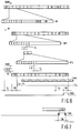
- Fig. 6 shows a TDMA frame structure used in the telecommunication system 1, illustrating coarse ranging according to the present invention. Shown are a multiframe down in downstream direction and a multiframe up in upstream direction.
- the main station 2 transmits multiframe down, assembled with the assembler 13 in downstream direction.
- the multiframe down comprises a sync time slot SY allowing the substations to synchronize to the main station multiframe down and to extract the time slots allocated to them.
- the multiframe down comprises 16 basic frames BF, each having 1024 time slots available for data transport and each having housekeeping time slots HK.
- the upstream multiframe up has a similar structure as to data and housekeeping time slots, but instead of a sync time slot, a time window CR is reserved in the frame for ranging purposes.
- the time window CR substantially coincides with a window FR reserved in the frame for fine ranging, at a corresponding location in the upstream multiframe up.
- a coarse ranging request could be initiated in a given multiframe, and coarse ranging samples could be taken in the next succeeding frame within the same time window that would otherwise be used for fine ranging.
- both coarse and fine ranging is done, such ranging would give rise to a better frame efficiency as compared with systems using separate windows for coarse and fine ranging.
- the main station 2 sets a fixed delay D f for the multiframe up for communication in upstream direction with respect to the multiframe down, i.e. the main station sets a fixed reference for listening to the substations 4 to 7.
- samples are taken inside a time window TW which substantially does not overlap with data time slots in the basic frames BF.
- TW time window
- many subscribers can be serviced. Assuming one time slot per subscriber, in the given example 1024 subscribers can be serviced at a time. When subscribers occupy more time slots, the total number of subscribers which can be serviced at a time is less.
- a number of subscribers can coupled, whereby to each subscriber a time slot or a number of time slots can be allocated.
- time slots may be allocated dynamically later on.
- a given substation to which a time slot 4 and possibly other time slots are to be allocated in the basic frame BF is to be coarse-ranged.
- the relevant substation when not coarse-ranged yet, would transmit the time slot 4 is a shifted position such that interference with another time slot would occur. This is indicated with a time slot 4'.
- a delay in the substation is adjusted such that a time delay t d is eliminated.
- the relevant subscriber would transmit data in corresponding time slots of successive basic frames BF1, BF2, etc.
- the relevant substation determines its transmission delay with respect to a fixed reference point, e.g. with respect to the received sync time slot SY.
- the frames are shown as a function of time t.
- the coarse ranging sequence rseq is sampled in the time window TW by means of the analog-to-digital converter 41 in the main station 2, enabled by the time window signal TWS.
- the time window TW normally no substation will transmit data, i.e. no interference with data will occur and only receiver noise is present. Consequently, the signal-to-interference ratio in the time window TW is an order of magnitude better than in the other part of the multiframe up. Due to the improved signal-to-interference ratio the phase of the Pseudo Noise Sequence can be determined more accurately without prefiltering being necessary.
- Fig. 7 shows a part of the TDMA frame structure with respect to an embodiment of the present invention in which the time window signal TWS is slightly broader than in the previous example given.
- the frame structure is similar to the structure shown in Fig. 6.
- the overlapping range should not be too broad due to the then occurring interference with data signals, reducing the advantages of the present invention.
- a simple filter such as a second order Chebyshev-filter could be applied, filtering out higher frequency data components.
- Fig. 8 shows a frequency spectrum of ranging bits and data in an embodiment of the present invention.
- the above mentioned Chebyshev-filter, the low-pass filter 42 in the main station 2 could have a cut-off frequency of the Pseudo Noise Sequence bit frequency, whereas the data frequency would be a factor four higher, thus filtering out higher frequency data components.
- the coarse ranging means 40 and/or the fine ranging means 28 are comprised in the main station 2, i.e. a centralized system is described.
- the coarse and/or fine ranging means 40 and 28 are comprised in the substations 4 to 7.
- the main station 2 acts as a relay station for relaying the ranging information transmitted by the substations 4 to 7.
- the ranging process may be started on the initiative of the main station 2 or on the initiative of the substations 4 to 7 to be ranged.
Landscapes
- Engineering & Computer Science (AREA)
- Computer Networks & Wireless Communication (AREA)
- Signal Processing (AREA)
- Time-Division Multiplex Systems (AREA)
- Small-Scale Networks (AREA)
- Data Exchanges In Wide-Area Networks (AREA)
- Synchronisation In Digital Transmission Systems (AREA)
Abstract
Description
- The present invention relates to a telecommunication system comprising a main station and a plurality of substations, in which system communication between the main station and the substations occurs via a transmission channel on the basis of a multiple access protocol, which channel is at least partially common to the substations, for the sake of coarse ranging the substations being provided with ranging transmission means for transmitting a low magnitude ranging sequence with respect to the magnitude of data to be transmitted in time slots, and the main station being provided with correlation means for recovering ranging information by correlating a received ranging sequence with a reference sequence being identical to the transmitted sequence, the main station being provided with means for providing the reference sequence. Depending on the transmission channel used, i.e. a glass fibre, a coaxial cable or a radio link, the telecommunication system can be a passive optical network (PON), a local area network, a satellite communication system or a cellular mobile radio system.
- The present invention further relates to a main station for use in such a system.
- A telecommunication system of this kind is known from the article, "Burst and bit synchronization methods for passive optical networks", C.A. Eldering et a., 4th Workshop on Optical Local Networks, IEEE, Sep. 24, 25 1992, Versailles, France, pp. 38-44. In the article various synchronization techniques are described, such as burst synchronization or coarse ranging, such synchronization being necessary to prevent substations from interfering each other due to non-synchronized operation, i.e. it is to be prevented that data transmitted from the substations to the main station do not arrive at the main station simultaneously. In the known telecommunication system, an optical network, the main station may transmit data and messages in time slots within a frame to the substations, in the downstream direction, in a controlled way, i.e. the main station or master has full control over the timing of the data to be transmitted to the various substations. In the upstream direction, from the substations to the main stations the most commonly technique is a Time Division Multiple Access Technique (TDMA), which requires that the delays between the substations and the main station be known and that a suitable delay be incorporated in the transmission from each substation so that the burst transmissions arrive at the specified or allocated time slots for the substations with respect to the main station timing. Such TDMA techniques can be used in combination with a frame structure or without a frame structure, the latter as ATM (Asynchronous Transfer Mode) cells to be transported using a TDMA protocol. Especially when no frame structure is present it becomes essential to have a non-intrusive coarse ranging for the ATM transport on fiber, but also with a frame structure a non intrusive coarse ranging method can be used, i.e. a method which practically does not interfere with the transmissions from in-service substations. On
page 41 of said IEEE article a non intrusive coarse ranging technique is disclosed based upon correlation techniques. The known coarse ranging technique, i.e. ranging with an accuracy of a few data bits, is based on correlation of transmitted and received sequences, and estimates the range between the main station and the substation of an out-of-service substation while the other substations may continue transmission of information. The substation to be ranged transmits a long ranging sequence with very low magnitude and at a lower speed than transmission of data (e.g. in a TDMA ATM architecture a bit period of the ranging sequence corresponds to a cell period). A sequence with good correlation properties is chosen, the low power being necessary to prevent data to be disturbed by the sequence, which behaves like a Pseudo Noise Sequence. The ranging sequence can be a maximum length sequence with finite length (2n-1), i.e. a sequence obtainable with a linear feedback shift register or a linear sequence generator, described in numerous handbooks on Logic Design. At the main station side, the ranging information can be recovered from the received ranging sequence using correlation techniques. Therefore, the received signal is sampled in the main station's receiver and correlated with the transmitted, i.e. known, maximal length sequence. In Fig. 6,page 41 of said IEEE article for this purpose a correlation receiver is disclosed, an output of which giving an immediate indication of the delay between the main station and the substation to be ranged. Apart from mentioning that experiments were carried out with maximum length sequences of 15 to 127 bit in this coarse ranging system, no implementation is disclosed with respect to the correlator. The correlation has been described in relation to TDMA ATM, having no frame structure. The IEEE-article further discloses coarse ranging techniques with respect to a TDMA based PON having a frame structure, these techniques being based upon recognition in the main station of ranging bits to be transmitted in preambles of bursts by the substations. Because of the fact that the magnitude of the ranging bits is in the same order as the magnitude of the data to be transmitted by other substations, a ranging window is provided with the main station's frame to allow substations which are coming into service to transmit bursts for coarse ranging purposes. - In the
PCT Application WO 91/06157 a passive optical network is disclosed with a frame based TDMA communication protocol in which network upstream TDMA frames are transmitted from the substations to the main station with ranging pulses for coarse ranging and ranging pulses for fine ranging to compensate for different delays associated with the substations with respect to the main station. As compared with the correlation technique disclosed in said IEEE-article with respect the frameless TDMA ATM system, extra bits are necessary for coarse and fine ranging, thus decreasing frame efficiency. - It is an object of the present invention to provide a more accurate coarse ranging correlation technique for an operational telecommunication system.
- To this end a telecommunication system according to the present invention is characterized in that the communication is frame based, and in that for coarse ranging the correlation means only correlate samples of the received ranging sequence substantially falling inside a time window reserved in the frame for ranging. The present invention is based upon the insight that in a system in operation operational substations are monitored by the main station in a ranging window, preferably a fine ranging window, in which window no data interference is present, the ranging sequence in principle being transmitted during a complete upstream multiframe. This time window, the time position of which is known to the main station, and preferably being reserved for fine ranging is used during coarse ranging for acquiring samples to be correlated with the reference sequence, the samples thus substantially being free of interference with data from other substations already in operation. Consequently, the signal to interference ratio of the received coarse ranging signal is an order of magnitude better than in other parts of the frame. Due to the improved signal to interference ratio the phase of the received ranging sequence with respect to the reference sequence can be determined more accurately as compared with a low magnitude ranging sequence having the same magnitude in a system where correlation samples would be acquired at a random position within the frame. In such a system the correlation process would be subject to low frequency components of the data from other substations and to receiver noise. Although the ranging sequence can be operated at the data bitrate, for practical reasons it is advantageous to apply a ranging sequence bitrate being a fraction of the data bitrate, e.g. 0.1, in order to avoid high sampling rates within the system. The magnitude of the coarse ranging sequence in the system according to the invention can be reduced with respect to a sequence sampled in a randomly chosen window. In the latter case the still lower magnitude ranging sequence interferes less with the data of operational substations, giving overall better system performance. In ease of a telecommunication system with one kind of ranging, such as a mobile radio system, the ranging according to the present invention is applied by sampling in a reserved window only.
- In an embodiment of the system according to the present invention, the bitrate of the ranging sequence is lower than the data bitrate of the substations, and in addition to correlation of samples of the received ranging sequence inside the time window, the correlation means correlate samples of the received ranging sequence outside the time window, substantially more samples being taken inside the time window than outside the time window. In this embodiment more samples are available for correlation so that the phase of the received sequence can be determined more accurately.
- In a further embodiment of a system according to the present invention, the main station comprises a low-pass filter for filtering the received ranging sequence before being fed to the correlation means, the low-pass filter having a cut-off frequency substantially coinciding with the frequency of the received ranging signal. If the ranging sequence bitrate is lower than the data bitrate, higher frequency components of the data are suppressed, improving system performance due to an increased signal to interference ratio for coarse ranging samples outside the fine ranging window. In fact the latter is a combined use of a selectively chosen correlation window as of the present invention and an out-of-band signalling technique. Out-of-band signalling techniques are known per se from the said IEEE article,
page 40. - The present invention will now be described, by way of example, with reference to the accompanying drawings, wherein
- Fig. 1 schematically shows a telecommunication system according to the present invention,
- Fig. 2 shows a main station for use in the telecommunication system according to the present invention,
- Fig. 3 shows processing means for processing coarse ranging samples according to the present invention,
- Fig. 4 shows an embodiment of a correlator for use in the processing means,
- Fig. 5 shows a substation for use in the telecommunication system,
- Fig. 6 shows a TDMA frame structure used in the telecommunication system, illustrating coarse ranging according to the present invention,
- Fig. 7, shows the TDMA frame structure with respect to an embodiment of the present invention, and
- Fig. 8 shows a frequency spectrum of ranging bits and data in an embodiment of the present invention.
- Throughout the figures the same reference numerals are used for the same features.
- Fig. 1 schematically shows a
telecommunication system 1 according to the present invention comprising amain station 2 communicating via atransmission channel 3 with a plurality ofsubstations channel 3, which at least partially is common to thesubstations 4 to 7, is a glass fibre cable in case thetransmission system 1 is a Passive Optical Network (PON), also called PON-FITL-System (Fibre in the Loop). Themain station 2 can be a local telephone exchange and to thesubstations 4 to 7 a subscriber or a group of subscribers can have access to various services such as telephone, facsimile and telex. In the latter case the system is so-called TPON (Telephone Passive Optical Network). In a PON splitting and combining of optical signals on the channel for transport of information to and from themain station 2 is well-known. For details referred is to general art in this field. Thetelecommunication system 1 can also be a mobile radio telephony system, in which the main station orstations 2 are fixed stations and thesubstations 4 to 7 are mobile stations such as portable telephones, mobile telephones etc., thetransmission channel 3 then being a radio link. In thetelecommunication system 1 multiple access protocol based communication between themain station 2base stations 4 to 7 occurs, such as TDMA (Time Division Multiple Access), well-known in the art. In such asystem 1 the main station, being a master controlling thesystem 1, transmits TDMA-frames, to be described in the sequel, to thesubstations 4 to 7, in a so-called downstream direction, whereas thesubstations 4 to 7 transmit information in an upstream direction to themain station 2. In such asystem 1 access conflicts may arise if not special measures are taken with respect to timing of the upstream communication, varying and different transmission delays and frame positions to be adjusted in the substations before transmission. In the cited IEEE-article to this end coarse ranging is described, and in the citedWO 91/06157 both coarse ranging and fine ranging. The present invention provides an improved coarse ranging method, to be described in the sequel, suitable for a system in operation, i.e. a system in which substations are ranged while other substations are in operation. The coarse ranging method according to the present invention can also be used at system start-up where no substations are in operation yet. - Fig. 2 shows a
main station 2 for use in thetelecommunication system 1 according to the present invention suitable for transmission and reception of TDMA signals. Themain station 2 comprises atransmitter branch 10 and areceiver branch 11 coupled to atransmission channel 12. In thetransmitter branch 10 subscriber signals for various substations are fed to aframe assembler 13 via amultiplexer 14. The multiplexed signal, also comprising synchronising and as the case may be coarse and fine ranging control information, is fed to thechannel 12 after being coded in acoder 15 via transmitter a 16. Channel coding is done for achieving a suitable frequency spectrum on the channel. Signals from thesubstations 4 to 7 are received by areceiver 17, an output of which is coupled to frame disassembling means 18 for providing information to various subscribers via ademultiplexer 19. The disassembling means 18 comprise adecoder 21 which is coupled to a frame disassembler 22. Thedecoder 21 and the disassembler 22 are provided with a clock signal by aPhase Adjustment circuit 23. Themain station 2 further comprises timing and control means 24 comprising a system or master clock circuit for providing a master clock fb, being fed to thePhase Adjustment circuit 23 and to theframe assembler 13 inter alia. The master clock fb is divided by N, N being an integer, in adivider circuit 26 such that a clock fb/N is achieved. The clock fb/N is fed to a clock-enable circuit 27 enabling the clock fb/N with a time window signal TWS. A sample clock fs, being a windowed clock fb/N is used in coarse ranging according to the present invention. The timing and control means 24 further provide a start signal S to be used in coarse ranging according to the present invention, the start signal S being a fixed reference for themain station 2 for determining transmission delays or round-trip delay of thesubstations 4 to 7. The disassembler 22 is further coupled to fine ranging determining means 28 for determining fine delay information from fine ranging pulses transmitted by thesubstations 4 to 7 at request of themain station 2. The fine ranging control information is assembled in the frames to be transmitted to thesubstations 4 to 7 by theframe assembler 13. Thereceiver 17 is further coupled to coarse ranging means 40 comprising an analog-to-digital converter 41 sampling a low magnitude ranging sequence rseq transmitted to themain station 2 by anysubstation 4 to 7 at request of themain station 2. According to the present invention the low magnitude coarse ranging sequence is substantially only sampled when it is sure that no data from other substations are present, or in a slightly modified form with slight overlap with possible data carrying parts of the frame, i.e. in a fine ranging window of which the position is known to themain station 2. In the latter case it is advantageous to chose a sample clock fs having a lower frequency than the bit clock or master clock fb, and applying a low-pass filter 42 to filter out higher frequency components of data signals. In case of substantially no overlap the filter can be dispensed with, thus achieving a simpler and cheaper system. Coarse ranging samples crs at an output of the analog-to-digital converter 41 are fed to processing means 43 for processing the coarse ranging samples. The processing means 43 provide coarse ranging information to theframe assembler 13, so that coarse ranging control information is transmitted to the substation to be coarse-ranged. The substation to be coarse ranged adjusts its delay before switching over to an active state for transmission of data signals, so that after coarse ranging fine ranging can take place at request of themain station 2, if required, or at regular intervals. - Fig. 3 in more detail shows the processing means 43 for processing coarse ranging samples crs according to the present invention. The processing means 43 comprise a
memory 50 for storing the coarse ranging samples crs, which is coupled to acorrelator 51. The coarse ranging signals crs stored in thememory 50 are stored as a digital signal A in a first shift register, to be shown later on, a second shift register, to be shown later on, of thecorrelator 51 comprising a part of the a priori known coarse ranging sequence as a digital signal B, stored or generated in themain station 2 and generated in the substation to be coarse-ranged. By correlating parts of the coarse ranging sequence and shifting the coarse ranging sequence through thecorrelator 51, from the phase shift or position within the a priori known coarse ranging sequence the round trip delay be determined, the delay in the a prior known ranging sequence being a measure of the round trip delay. For determining maximum correlation with each time a different part of the sequence, the processing means 43 comprise apeak detector 52, which is coupled to amicrocontroller 53 including a microprocessor, RAM and ROM memory and I/O-interfaces, as usual. For determining relative delay with respect to the beginning of the frame each time, acounter 54 is provided. The a priori known sequence is generated with reference signal generating means 55, the reference sequence being a maximum length sequence e.g. generated by a polynomial 1 + x + x¹⁵ of length 2¹⁵-1, the sequence being longer than a multiframe to be transmitted by themain station 2, i.e. it is ensured that the ranging window in a next upstream multiframe is always filled with a part of the transmitted sequence by the substation. If a priori knowledge about the round trip delay is available a shorter sequence may be chosen. Chosen is a low power sequence with good correlation properties, the low power being necessary to prevent data to be disturbed by the sequence, which behaves like a Pseudo Noise Sequence. Because the phase of the Pseudo Noise sequence is not known in themain station 2, oversampling of the Pseudo Noise Sequence is necessary. Since the sampling clock fs is preferably chosen equal to the bit clock fb, the frequency of the Pseudo Noise Sequence has to be reduced accordingly. With the coarse ranging according to the present invention a coarse ranging accuracy in the order of 1 bit of the Pseudo Noise Sequence can be obtained. The signal S provided by the timing and control means 24 assures appropriate timing with respect to the main station's multiframe. - Fig. 4 shows an embodiment of the
correlator 51 for use in the processing means 43. As described with respect to figure 3, the coarse ranging symbols A are stored in afirst shift register 60, and symbols B, being a part of the reference Pseudo Noise sequence, are stored in asecond shift register 61. Respective outputs ofmultipliers second shift register adder 67 an output of which giving a correlation value which is fed to themicrocontroller 53. Thecounter 54 is reset and started by means of the signal S. At each counter value a correlation value is determined and respective counter outputs are stored in a lookup table in themicrocontroller 53 together with corresponding correlation values, and by then looking up the maximum correlation value with its corresponding counter value, the coarse offset delay can be calculated and transmitted to the respective substation. Instead of applying a lookup table apeakdetector 52 can be used to locate the maximum correlation value. Then, with each counter value the correlation value is compared with a previous maximum correlation value, and the maximum correlation value is updated if the current value exceeds the previous maximum value, together with the corresponding counter value. It is thus achieved that after correlation the maximum correlation value and the corresponding counter value are immediately available. The calculation algorithm, which correlates the sampled part of the sequence with the original sequence is as follows:
M being the number of samples, the sampled sequence being ai, i = 1, 2, ..., M, and the original maximum length sequence being bi, i = 1, 2, 3, ...., 2¹⁵-1. The coefficients bi are +1 or -1, with equal probability, i.e.
substations 4 to 7 and themain station 2. It should hold that jmax.T is greater than the maximum delay, T being the symbol period. A fixed delay Df is set between downstream and upstream multiframes. For a location index j₀ corresponding to the maximum value of the correlation values cj, the coarse delay offset Ec is:

Thecorrelator 51 can also be implemented in software, loaded in ROM or EPROM of themicrocontroller 53, i.e. the above algorithm can be implemented in hardware and in software. The maximum correlation value, which is a measure of the received power in themain station 2, is also used for power control purposes. To this end themain station 2 determines a measure of the received power from the maximum correlation value, compares the measure with a desired measure and transmits power control information to thesubstations 4 to 7 in the form of a deviation of the measure of the received power from the desired measure. Thesubstations 4 to 7 adjust their transmission power accordingly. At the end, it is thus achieved that all substation signals are received by themain station 2 with substantially equal power. - Fig. 5 shows a
substation 4 for use in thetelecommunication system 1 according to the present invention. Thesubstation 4 comprises areceiver branch 70 and a transmitter branch 71 coupled to thetransmission channel 12. Thereceiver branch 70 comprises a series arrangement of areceiver 72, adecoder 73, aframe disassembler 74 and ademultiplexer 75. At a receiver output a clock is recovered by means of aclock recovery circuit 76, whereas async detector 77 is coupled with an output of thedecoder 73. The transmitter branch 71 comprises a series arrangement of amultiplexer 80, coarse and fine adjustment means 81, acoder 82, and atransmitter 83. Functionally, thesubstations 4 to 7 operate similar to themain station 2, as far as transmission and reception is concerned. The coarse and fine adjustment means 81 comprise a coarsedelay adjustment section 84 and a finedelay adjustment section 85, both coupled to theframe disassembler 74, which provides coarse and fine adjustment control information from themain station 2 via housekeeping time slots in the downstream multiframe. In order to obtain fine adjustments smaller than a symbol period, the finedelay adjustment section 85 can be clocked with a higher frequency than the symbol frequency fb. To this end, theclock recovery circuit 76 comprises a separate clock output with a higher clock. For generating the low magnitude ranging sequence to be transmitted to themain station 2, thesubstation 4 comprises sequence generating means 90 comprising a PseudoNoise Signal generator 91, acoder 92 which is coupled to thetransmitter 83.PNS generator 91 and thecoder 92 are clocked by a clock fb/N, derived from an output of theclock recovery circuit 76, the output being fed to adivider circuit 93. The sequence generating means are initiated at a request for coarse ranging originating from themain station 2 and are actually started at a predetermined time reference with respect to the received multiframe down. Thesubstation 4 also comprises power adjustment means 94 which are coupled to thetransmitter 83 and to theframe disassembler 74, the power adjustment means 94 adjusting the power to be transmitted by thesubstation 4 in accordance with the received power control information transmitted by themain station 2. - Fig. 6 shows a TDMA frame structure used in the
telecommunication system 1, illustrating coarse ranging according to the present invention. Shown are a multiframe down in downstream direction and a multiframe up in upstream direction. Themain station 2 transmits multiframe down, assembled with theassembler 13 in downstream direction. In the given example, the multiframe down comprises a sync time slot SY allowing the substations to synchronize to the main station multiframe down and to extract the time slots allocated to them. In the given example, the multiframe down comprises 16 basic frames BF, each having 1024 time slots available for data transport and each having housekeeping time slots HK. Preferably, the upstream multiframe up has a similar structure as to data and housekeeping time slots, but instead of a sync time slot, a time window CR is reserved in the frame for ranging purposes. In a preferred embodiment, the time window CR substantially coincides with a window FR reserved in the frame for fine ranging, at a corresponding location in the upstream multiframe up. In the latter case a coarse ranging request could be initiated in a given multiframe, and coarse ranging samples could be taken in the next succeeding frame within the same time window that would otherwise be used for fine ranging. In systems in which both coarse and fine ranging is done, such ranging would give rise to a better frame efficiency as compared with systems using separate windows for coarse and fine ranging. Themain station 2 sets a fixed delay Df for the multiframe up for communication in upstream direction with respect to the multiframe down, i.e. the main station sets a fixed reference for listening to thesubstations 4 to 7. According to the present invention samples are taken inside a time window TW which substantially does not overlap with data time slots in the basic frames BF. In thesystem 1 many subscribers can be serviced. Assuming one time slot per subscriber, in the given example 1024 subscribers can be serviced at a time. When subscribers occupy more time slots, the total number of subscribers which can be serviced at a time is less. In thesystem 1 to eachsubstation 4 to 7 a number of subscribers can coupled, whereby to each subscriber a time slot or a number of time slots can be allocated. Once a substation is coarse-ranged time slot allocation can take place. Also, to a ranged substation, time slots may be allocated dynamically later on. In the given example it is assumed that a given substation to which atime slot 4 and possibly other time slots are to be allocated in the basic frame BF is to be coarse-ranged. It is further assumed that the relevant substation, when not coarse-ranged yet, would transmit thetime slot 4 is a shifted position such that interference with another time slot would occur. This is indicated with a time slot 4'. With the coarse ranging according to the present invention it is achieved that a delay in the substation is adjusted such that a time delay td is eliminated. It is to be noticed that the relevant subscriber would transmit data in corresponding time slots of successive basic frames BF1, BF2, etc. The relevant substation determines its transmission delay with respect to a fixed reference point, e.g. with respect to the received sync time slot SY. The frames are shown as a function of time t. At t=t₀, the substation, to which thetime slot 4 and possibly other time slots are to be allocated, receives a coarse ranging request and transmits a low power coarse ranging sequence rseq at t=t₁, in a given example, assuming no a priori knowledge about the transmission delay, the ranging sequence being longer than a multiframe up. According to the present invention, the coarse ranging sequence rseq is sampled in the time window TW by means of the analog-to-digital converter 41 in themain station 2, enabled by the time window signal TWS. During the time window TW normally no substation will transmit data, i.e. no interference with data will occur and only receiver noise is present. Consequently, the signal-to-interference ratio in the time window TW is an order of magnitude better than in the other part of the multiframe up. Due to the improved signal-to-interference ratio the phase of the Pseudo Noise Sequence can be determined more accurately without prefiltering being necessary. - Fig. 7 shows a part of the TDMA frame structure with respect to an embodiment of the present invention in which the time window signal TWS is slightly broader than in the previous example given. For the rest the frame structure is similar to the structure shown in Fig. 6. In this embodiment there is a slight overlap with data carrying time slots. Because of a having more samples available the correlation process is more accurate. The overlapping range should not be too broad due to the then occurring interference with data signals, reducing the advantages of the present invention. Although a cheaper solution is obtained without a filter being applied prefiltering the sequence in the main station at reception, in this embodiment a simple filter such as a second order Chebyshev-filter could be applied, filtering out higher frequency data components.
- Fig. 8 shows a frequency spectrum of ranging bits and data in an embodiment of the present invention. The above mentioned Chebyshev-filter, the low-
pass filter 42 in themain station 2 could have a cut-off frequency of the Pseudo Noise Sequence bit frequency, whereas the data frequency would be a factor four higher, thus filtering out higher frequency data components. - In the example given the coarse ranging
means 40 and/or the fine ranging means 28 are comprised in themain station 2, i.e. a centralized system is described. In another, decentralized, embodiment the coarse and/or fine ranging means 40 and 28 are comprised in thesubstations 4 to 7. Then, themain station 2 acts as a relay station for relaying the ranging information transmitted by thesubstations 4 to 7. The ranging process may be started on the initiative of themain station 2 or on the initiative of thesubstations 4 to 7 to be ranged.
Claims (8)
- A telecommunication system (1) comprising a main station (2) and a plurality of substations (4 to 7), in which system (1) communication between the main station (2) and the substations (4 to 7) occurs via a transmission channel (12) on the basis of a multiple access protocol (TDMA), which channel (12) is at least partially common to the substations (4 to 7), for the sake of coarse ranging the substations (4 to 7) being provided with ranging transmission means (90) for transmitting a low magnitude ranging sequence with respect to the magnitude of data to be transmitted in time slots, and the main station (2) being provided with correlation means (43) for recovering ranging information by correlating a received ranging sequence (rseq) with a reference sequence being identical to the transmitted sequence, the main station (2) being provided with means for providing the reference sequence, characterized in that the communication is frame based, and in that for coarse ranging the correlation means (43) only correlate samples of the received ranging sequence substantially falling inside a time window (CR) reserved in the frame for ranging.
- A telecommunication system (1) according to claim 1, wherein the time window (CR) substantially coincides with a window (FR) reserved in the frame for fine ranging.
- A telecommunication system (1) according to claim 1 or 2, in which the bitrate of the ranging sequence (fb/N) is lower than the data bitrate of the substations (fb), and in which in addition to correlation of samples of the received ranging sequence inside the time window (CR), the correlation means (43) correlate samples of the received ranging sequence outside the time window (CR), substantially more samples being taken inside the time window than outside the time window.
- Telecommunication system according to claim 3, wherein the main station comprises a low-pass filter (42) for filtering the received ranging sequence (rseq) before being fed to the correlation means (43), the low-pass filter (42) having a cut-off frequency substantially coinciding with the frequency (fb/N) of the received ranging signal (rseq).
- Telecommunication system (1) according to any one of the preceding claims, wherein the correlation means determine a maximum correlation value by correlating the received ranging sequence (rseq) with the reference sequence for each substation to be coarse-ranged, determine a received power measure from the maximum correlation values, and transmit power control information to the substations for adjustment of transmitting power in accordance with a deviation of the power measure with respect to a desired power measure, the substations comprising power adjustment means for adjusting the transmitting power in accordance with the power control information.
- A telecommunication system (1) comprising a main station (2) and a plurality of substations (4 to 7), in which system (1) communication between the main station (2) and the substations (4 to 7) occurs via a transmission channel (12) on the basis of a multiple access protocol (TDMA), which channel (12) is at least partially common to the substations (4 to 7), for the sake of coarse ranging the substations (4 to 7) being provided with ranging transmission means (90) for transmitting a low magnitude ranging sequence with respect to the magnitude of data to be transmitted in time slots, being provided with correlation means for recovering ranging information by correlating a received ranging sequence (rseq) relayed by the main station with a reference sequence being identical to the transmitted sequence, and being provided with means for providing the reference sequence, characterized in that the communication is frame based, and in that for coarse ranging the correlation means only correlate samples of the received ranging sequence substantially falling inside a time window (CR) reserved in the frame for ranging.
- Main station (2) for use in a telecommunication system (1) according to any one of the claims 1 to 5, comprising receiving means (17, 18) for receiving data in time slots from substations (4 to 7), and for receiving ranging sequences (rseq) to be transmitted by the substations (4 to 7) for the sake of coarse ranging, and further comprising correlation means (43) for recovering ranging information by correlating a received ranging sequence (rseq) with a reference sequence being identical to the transmitted sequence, the main station (2) being provided with means for providing the reference sequence, characterized in that the communication is frame based, and in that for coarse ranging the correlation means (43) only correlate samples of the received ranging sequence (rseq) substantially falling inside a time window (CR) reserved in the frame for ranging.
- Main station according to claim 7, wherein the correlation means determine received power measures from maximum correlation values and transmit power control information to the substations for power adjustment in accordance with a deviation of the received power measures with respect to desired power measures.
Applications Claiming Priority (2)
| Application Number | Priority Date | Filing Date | Title |
|---|---|---|---|
| EP93200743 | 1993-03-15 | ||
| EP93200743 | 1993-03-15 |
Publications (2)
| Publication Number | Publication Date |
|---|---|
| EP0616444A2 true EP0616444A2 (en) | 1994-09-21 |
| EP0616444A3 EP0616444A3 (en) | 1994-10-19 |
Family
ID=8213698
Family Applications (1)
| Application Number | Title | Priority Date | Filing Date |
|---|---|---|---|
| EP9494200597A Withdrawn EP0616444A3 (en) | 1993-03-15 | 1994-03-09 | Telecommunication system with ranging. |
Country Status (4)
| Country | Link |
|---|---|
| US (1) | US5619504A (en) |
| EP (1) | EP0616444A3 (en) |
| JP (1) | JP3575771B2 (en) |
| CA (1) | CA2118848A1 (en) |
Cited By (5)
| Publication number | Priority date | Publication date | Assignee | Title |
|---|---|---|---|---|
| WO1996013915A1 (en) * | 1994-10-27 | 1996-05-09 | Nokia Telecommunications Oy | Ranging process for point-to-multipoint communication systems |
| WO1997001896A1 (en) * | 1995-06-27 | 1997-01-16 | British Telecommunications Public Limited Company | Synchronisation in digital communications networks |
| EP2472753A1 (en) * | 2011-01-04 | 2012-07-04 | Alcatel Lucent | Method of delay measurement in an optical network |
| EP2615752A1 (en) * | 2012-01-16 | 2013-07-17 | Alcatel Lucent | Computation of a delay difference in an optical network |
| EP3550742A1 (en) * | 2018-04-03 | 2019-10-09 | Nokia Solutions and Networks Oy | Optical network unit activation |
Families Citing this family (33)
| Publication number | Priority date | Publication date | Assignee | Title |
|---|---|---|---|---|
| CA2120542C (en) * | 1994-04-05 | 2003-07-08 | Tom Gray | Cell relay transport mechanism |
| US6334219B1 (en) * | 1994-09-26 | 2001-12-25 | Adc Telecommunications Inc. | Channel selection for a hybrid fiber coax network |
| USRE42236E1 (en) | 1995-02-06 | 2011-03-22 | Adc Telecommunications, Inc. | Multiuse subcarriers in multipoint-to-point communication using orthogonal frequency division multiplexing |
| US7280564B1 (en) | 1995-02-06 | 2007-10-09 | Adc Telecommunications, Inc. | Synchronization techniques in multipoint-to-point communication using orthgonal frequency division multiplexing |
| EP0758822B1 (en) * | 1995-08-11 | 2006-03-01 | Alcatel | Method and arrangement for dynamic allocation of bandwidth in a TDM/TDMA network |
| US6327266B1 (en) * | 1997-04-25 | 2001-12-04 | Alcatel Usa Sourcing, L.P. | Multiple user access network |
| US6278697B1 (en) * | 1997-07-29 | 2001-08-21 | Nortel Networks Limited | Method and apparatus for processing multi-protocol communications |
| DE69905242T2 (en) * | 1998-04-21 | 2003-09-11 | Thomson Multimedia Sa | METHOD FOR TRANSMITTING IN A HOME COMMUNICATION NETWORK WITH A WIRELESS COMMUNICATION CHANNEL |
| EP1021012A1 (en) * | 1999-01-11 | 2000-07-19 | International Business Machines Corporation | Communications network system for multiple access |
| US6166573A (en) * | 1999-07-23 | 2000-12-26 | Acoustic Technologies, Inc. | High resolution delay line |
| JP3259776B2 (en) * | 1999-08-24 | 2002-02-25 | 日本電気株式会社 | Transmission circuit |
| RU2174738C1 (en) * | 2000-10-31 | 2001-10-10 | ЗАО "НПО "Кросна" | Baseband echo compensation method and baseband echo compensator |
| JP3877579B2 (en) * | 2001-11-26 | 2007-02-07 | 古野電気株式会社 | TDMA communication device |
| US7403583B1 (en) * | 2003-02-19 | 2008-07-22 | L-3 Communications Corporation | System and method for predictive synchronization for locating interleaving frames and demodulation training sequences |
| JP2005184335A (en) * | 2003-12-18 | 2005-07-07 | Oki Electric Ind Co Ltd | Missynchronization preventing device in wireless communication device |
| US7583735B2 (en) * | 2005-03-31 | 2009-09-01 | Adc Telecommunications, Inc. | Methods and systems for handling underflow and overflow in a software defined radio |
| US7474891B2 (en) * | 2005-03-31 | 2009-01-06 | Adc Telecommunications, Inc. | Dynamic digital up and down converters |
| US20060222019A1 (en) * | 2005-03-31 | 2006-10-05 | Adc Telecommunications, Inc. | Time stamp in the reverse path |
| US7424307B2 (en) * | 2005-03-31 | 2008-09-09 | Adc Telecommunications, Inc. | Loss of page synchronization |
| US20060223514A1 (en) * | 2005-03-31 | 2006-10-05 | Adc Telecommunications, Inc. | Signal enhancement through diversity |
| US20060227805A1 (en) * | 2005-03-31 | 2006-10-12 | Adc Telecommunications, Inc. | Buffers handling multiple protocols |
| US7423988B2 (en) * | 2005-03-31 | 2008-09-09 | Adc Telecommunications, Inc. | Dynamic reconfiguration of resources through page headers |
| US7593450B2 (en) * | 2005-03-31 | 2009-09-22 | Adc Telecommunications, Inc. | Dynamic frequency hopping |
| US7640019B2 (en) * | 2005-03-31 | 2009-12-29 | Adc Telecommunications, Inc. | Dynamic reallocation of bandwidth and modulation protocols |
| US7398106B2 (en) * | 2005-03-31 | 2008-07-08 | Adc Telecommunications, Inc. | Dynamic readjustment of power |
| US20060222020A1 (en) * | 2005-03-31 | 2006-10-05 | Adc Telecommunications, Inc. | Time start in the forward path |
| US20070237188A1 (en) * | 2006-04-05 | 2007-10-11 | Miguel Joseph D | Method and apparatus for ONT ranging with improved noise immunity |
| KR100965688B1 (en) * | 2006-09-07 | 2010-06-24 | 삼성전자주식회사 | Ranging method and apparatus in communication system including relay station and system therefor |
| GB2463074B (en) * | 2008-09-02 | 2010-12-22 | Ip Access Ltd | Communication unit and method for selective frequency synchronisation in a cellular communication network |
| US20140064383A1 (en) * | 2012-08-31 | 2014-03-06 | Vixs Systems, Inc. | Video processing device with adjustable delay and methods for use therewith |
| CN102866627B (en) * | 2012-09-26 | 2014-05-07 | 桂林电子科技大学 | Beidou seamless high-precision time service implementation method and system |
| CN104038264B (en) * | 2014-04-22 | 2017-09-29 | 中国水产科学研究院渔业工程研究所 | Shortwave Communication System power autocontrol method |
| US11039229B2 (en) * | 2017-08-29 | 2021-06-15 | Cable Television Laboratories, Inc. | Systems and methods for coherent optics ranging and sensing |
Family Cites Families (6)
| Publication number | Priority date | Publication date | Assignee | Title |
|---|---|---|---|---|
| US3530252A (en) * | 1966-11-16 | 1970-09-22 | Communications Satellite Corp | Acquisition technique for time division multiple access satellite communication system |
| DE68915768T2 (en) * | 1989-06-23 | 1994-09-15 | Bell Telephone Mfg | COMMUNICATION SYSTEM. |
| GB8923488D0 (en) * | 1989-10-18 | 1989-12-06 | British Telecomm | Optical receiver |
| DE69130734T2 (en) * | 1991-06-04 | 1999-06-10 | Alcatel, Paris | Method for measuring the time delay of an equalization in a transmission system and associated transmission system |
| JP2768115B2 (en) * | 1992-03-13 | 1998-06-25 | 日本電気株式会社 | Base station transceiver |
| GB2272610B (en) * | 1992-11-12 | 1996-10-09 | Northern Telecom Ltd | Telecommunications systems |
-
1994
- 1994-03-09 EP EP9494200597A patent/EP0616444A3/en not_active Withdrawn
- 1994-03-11 JP JP04106394A patent/JP3575771B2/en not_active Expired - Fee Related
- 1994-03-11 CA CA002118848A patent/CA2118848A1/en not_active Abandoned
- 1994-03-14 US US08/213,483 patent/US5619504A/en not_active Expired - Fee Related
Cited By (10)
| Publication number | Priority date | Publication date | Assignee | Title |
|---|---|---|---|---|
| WO1996013915A1 (en) * | 1994-10-27 | 1996-05-09 | Nokia Telecommunications Oy | Ranging process for point-to-multipoint communication systems |
| WO1997001896A1 (en) * | 1995-06-27 | 1997-01-16 | British Telecommunications Public Limited Company | Synchronisation in digital communications networks |
| AU711593B2 (en) * | 1995-06-27 | 1999-10-14 | British Telecommunications Public Limited Company | Synchronisation in digital communications networks |
| US6262997B1 (en) | 1995-06-27 | 2001-07-17 | British Telecommunications | Synchronization in digital communications networks |
| CN1086878C (en) * | 1995-06-27 | 2002-06-26 | 英国电讯有限公司 | Synchronisation in digital communications networks |
| EP1648105A3 (en) * | 1995-06-27 | 2006-08-09 | BRITISH TELECOMMUNICATIONS public limited company | Synchronisation in digital communications networks |
| EP2472753A1 (en) * | 2011-01-04 | 2012-07-04 | Alcatel Lucent | Method of delay measurement in an optical network |
| WO2012093024A1 (en) * | 2011-01-04 | 2012-07-12 | Alcatel Lucent | Method of delay measurement in an optical network |
| EP2615752A1 (en) * | 2012-01-16 | 2013-07-17 | Alcatel Lucent | Computation of a delay difference in an optical network |
| EP3550742A1 (en) * | 2018-04-03 | 2019-10-09 | Nokia Solutions and Networks Oy | Optical network unit activation |
Also Published As
| Publication number | Publication date |
|---|---|
| JPH0730557A (en) | 1995-01-31 |
| CA2118848A1 (en) | 1994-09-16 |
| US5619504A (en) | 1997-04-08 |
| EP0616444A3 (en) | 1994-10-19 |
| JP3575771B2 (en) | 2004-10-13 |
Similar Documents
| Publication | Publication Date | Title |
|---|---|---|
| US5619504A (en) | Telecommunication system and a main station for use in such a system | |
| US5579321A (en) | Telecommunication system and a main station and a substation for use in such a system | |
| EP0891660B1 (en) | Synchronization method, and associated circuitry, for synchronizing a receiver with a transmitter | |
| CA2224605C (en) | Synchronisation in digital communications networks | |
| EP0295227B1 (en) | Digital time multiplexed mobile telephony system with an effective utilization of every time frame | |
| JPH09233034A (en) | Time division multiple access communication system and time division multiple access communication method | |
| AU7671296A (en) | Methods and apparatus for synchronizing timing of components of a telecommunication system | |
| US20040190638A1 (en) | Process for synchronization of communication involving multiple user equipments with a head-end equipment by means of OFDM modulation in the upstream channel | |
| MXPA97002009A (en) | Digi radiotelefony transmission time control | |
| WO1997020402A1 (en) | Signal acquisition via repeated access probe transmission | |
| EP3241280A1 (en) | Apparatus and method for synchronizing communication between systems with different clock rates | |
| US4827474A (en) | System and method of adjusting the interstation delay in an information transmission system | |
| KR20010033027A (en) | S-cdma fixed wireless loop system employing subscriber unit/radio base unit super-frame alignment | |
| EP1730913B1 (en) | Apparatus and method for compensating for data degradation | |
| JP2001502134A (en) | Improved synchronization of receiver with transmitter using early and late tests during coarse synchronization | |
| AU2002304583B2 (en) | Synchronisation method for the uplink channel in a point-to-multipiont communication with OFDM modulation | |
| WO1997017768A9 (en) | Method and apparatus for power control in a telephone system | |
| EP0860057A1 (en) | Method and apparatus for power control in a telephone system | |
| HU220211B (en) | Burst aligment procedure and cordless terminal | |
| EP0931390B1 (en) | Improved synchronization of a receiver with a transmitter using nonlinear transformation metrics | |
| CN1319296C (en) | Method for transferring synchronous signal in synchronous time gap of time division complexing radio communication system | |
| CN115243356B (en) | Static orbit satellite communication synchronization method based on absolute time synchronization | |
| EP1494378B1 (en) | Speech information freeze-out control method and equipment in mobile satellite communication system | |
| Kramer | The problem of upstream traffic synchronization in Passive Optical Networks | |
| AU5730599A (en) | Method and device for a full-duplex radio transmission system with code division multiple access |
Legal Events
| Date | Code | Title | Description |
|---|---|---|---|
| PUAI | Public reference made under article 153(3) epc to a published international application that has entered the european phase |
Free format text: ORIGINAL CODE: 0009012 |
|
| PUAL | Search report despatched |
Free format text: ORIGINAL CODE: 0009013 |
|
| AK | Designated contracting states |
Kind code of ref document: A2 Designated state(s): DE FR GB IT |
|
| AK | Designated contracting states |
Kind code of ref document: A3 Designated state(s): DE FR GB IT |
|
| 17P | Request for examination filed |
Effective date: 19950419 |
|
| RAP3 | Party data changed (applicant data changed or rights of an application transferred) |
Owner name: KONINKLIJKE PHILIPS ELECTRONICS N.V. |
|
| 17Q | First examination report despatched |
Effective date: 20030909 |
|
| GRAP | Despatch of communication of intention to grant a patent |
Free format text: ORIGINAL CODE: EPIDOSNIGR1 |
|
| STAA | Information on the status of an ep patent application or granted ep patent |
Free format text: STATUS: THE APPLICATION IS DEEMED TO BE WITHDRAWN |
|
| 18D | Application deemed to be withdrawn |
Effective date: 20051001 |