EP0616388B1 - Connector terminal - Google Patents
Connector terminal Download PDFInfo
- Publication number
- EP0616388B1 EP0616388B1 EP94104204A EP94104204A EP0616388B1 EP 0616388 B1 EP0616388 B1 EP 0616388B1 EP 94104204 A EP94104204 A EP 94104204A EP 94104204 A EP94104204 A EP 94104204A EP 0616388 B1 EP0616388 B1 EP 0616388B1
- Authority
- EP
- European Patent Office
- Prior art keywords
- shaft portion
- tubular portion
- projection
- insertion tubular
- terminal
- Prior art date
- Legal status (The legal status is an assumption and is not a legal conclusion. Google has not performed a legal analysis and makes no representation as to the accuracy of the status listed.)
- Expired - Lifetime
Links
- 238000003780 insertion Methods 0.000 claims description 63
- 230000037431 insertion Effects 0.000 claims description 63
- 230000007423 decrease Effects 0.000 claims description 3
- 238000010276 construction Methods 0.000 description 4
- 239000004020 conductor Substances 0.000 description 3
- 230000003247 decreasing effect Effects 0.000 description 3
- 230000002708 enhancing effect Effects 0.000 description 1
- 230000013011 mating Effects 0.000 description 1
- 238000012986 modification Methods 0.000 description 1
- 230000004048 modification Effects 0.000 description 1
Images

Classifications
-
- H—ELECTRICITY
- H01—ELECTRIC ELEMENTS
- H01R—ELECTRICALLY-CONDUCTIVE CONNECTIONS; STRUCTURAL ASSOCIATIONS OF A PLURALITY OF MUTUALLY-INSULATED ELECTRICAL CONNECTING ELEMENTS; COUPLING DEVICES; CURRENT COLLECTORS
- H01R13/00—Details of coupling devices of the kinds covered by groups H01R12/70 or H01R24/00 - H01R33/00
- H01R13/02—Contact members
- H01R13/193—Means for increasing contact pressure at the end of engagement of coupling part, e.g. zero insertion force or no friction
Definitions
- This invention relates to a connector terminal, and more particularly to a connector terminal for connecting large electrical currents.
- a male terminal is inserted into a female terminal, thereby forming an electrical connection.
- a highly reliable connection between the two terminals is required. Therefore, a construction shown in Fig. 7 is adopted. This figure shows one of many pairs of mating terminals provided in female and male connector housings that are to be fitted together.
- the female terminal 20 shown in Fig. 7 has an insertion tubular portion 21 at its front portion, and the male terminal 22 has a shaft portion 23, which can be inserted into the insertion tubular portion 21.
- the outer diameter of the shaft portion 23 is slightly larger than a bore diameter of the insertion tubular portion 21; and the shaft portion 23 is divided along an axial direction by an expanding slot 24 extending along a longitudinal axis thereof.
- the resilient restoring force of the male terminal 22 may be decreased, and as a result, the contact pressure is decreased.
- the outer diameter of a front end of the shaft portion 23 is larger than the bore diameter of the insertion tubular portion 21, and therefore the insertion at an initial stage is difficult.
- CH-A-256 321 discloses a connector terminal as defined in the first part of claim 1.
- an object of the invention is to provide a connector terminal in which the insertion of a terminal can be easily achieved, and connection reliability is enhanced.
- a connector terminal including a female terminal having an insertion tubular portion of a cylindrical shape, and a shaft-like male terminal insertable into the female terminal.
- the male terminal can be loosely fitted in the insertion tubular portion.
- the male terminal has an expanding slot formed therein, so that the male terminal can be deformed radially outward.
- a projection is provided at a predetermined depth within the insertion tubular portion for forcibly expanding the expanding slot of the male terminal to bring the male terminal into contact with an inner surface of the insertion tubular portion.
- a diameter of a front end portion of the male terminal is smaller than a bore diameter of the insertion tubular portion. Therefore, at initial and intermediate stages of an insertion operation, a minimal insertion force can be used.
- the projection is fitted into the expanding slot to forcibly deform the male terminal radially outward. As a result, the male terminal is in contact with the bore wall of the insertion tubular portion, thus electrically connecting the two connectors together.
- Figs. 1-4 show a first embodiment of the present invention.
- the charging connector includes charging connectors to be connected to the car and a charger, respectively.
- Terminals for allowing a relatively large current for example, 30 ⁇ 90A
- Each of the embodiments shown in the attached figures are for purposes of illustration and show only one of many possible pairs of male and female terminals for use in accordance with the invention, and the invention is not meant to be limited thereto.
- the male terminal 1 is made of an electrically-conductive material, and has at one end, for example, its rear end portion, a larger-diameter portion 2 serving as a cord insertion portion for inserting a covered portion of a wire W thereinto.
- a smaller-diameter portion 3 is provided in communication with the larger-diameter portion 2, and a conductor portion of the wire W is inserted into the smaller-diameter portion 3.
- a flange 4 is formed in a continuous relationship with the smaller-diameter portion 3, and a shaft portion 6 insertable into a female terminal 5 extends in one direction, for example, forwardly from the flange 4.
- the shaft portion 6 is divided into a bifurcated configuration by an expanding slot 7, which is formed in the shaft portion 6 and extends axially from one end face, for example, a front end face thereof to a vicinity of the flange 4.
- the shaft portion 6 can be resiliently deformed in an expansive direction, that is, in a diameter-increasing direction.
- the shaft portion 6 has at its front end a tapered opening 9 flaring outwardly into a conical shape.
- a conical projection 8 (described later) on the female terminal 5 can be fitted in the opening 9.
- the shaft portion 6 decreases in diameter progressively toward its front end.
- the female terminal 5 similar to the male terminal 1, is made of an electrically-conductive material, and has a larger-diameter portion 10, a smaller-diameter portion 11 and a flange 12. Extending in one direction, for example, forwardly from the flange 12 is an insertion tubular portion 13 into which the shaft portion 6 of the male terminal 1 is adapted to be inserted.
- the insertion tubular portion 13 is in the form of a hollow cylinder having a closed end, for example, a closed bottom and has a bore diameter slightly larger than an outer diameter of the front end portion of the shaft portion 6.
- the insertion tubular portion 13 has such an overall length such that when the shaft portion 6 is completely inserted into the insertion tubular portion 13 one end or edge, for example, a front end or edge of the insertion tubular portion 13 substantially abuts against the flange 4 of the male terminal 1.
- the projection 8 for forcibly expanding the shaft portion 6 is coaxially formed on and projected from the bottom surface of the insertion tubular portion 13.
- the projection 8 can be aligned with the tapered opening 9, and has a frusto-conical shape larger in size than the opening 9. Accordingly, when the male and female terminals 1 and 5 are completely connected together, the projection 8 fits in the opening 9, so that the shaft portion 6 is expanded to a diameter substantially equal to the bore diameter of the insertion tubular portion 13 over substantially the entire length thereof. Therefore, the entire shaft portion 6 is held in contact with the bore surface of the insertion tubular portion 13 at a predetermined contact pressure.
- the insertion of the male terminal 1 into the female terminal 5 is achieved.
- the insertion proceeds in such a manner that a predetermined gap is provided between the shaft portion 6 and the insertion tubular portion 13. Therefore, the operation of fitting of the two terminals together can be easily achieved, and the operating force required during the insertion is minimal.
- the projection 8 becomes fitted in the tapered opening 9 of the shaft portion 6.
- the shaft portion is forcibly inserted, and the opening 9 is expanded so that the entire shaft portion 6 is brought into contact with the inner surface of the insertion tubular portion 13 at the predetermined contact pressure.
- the insertion force required at an initial and intermediate stage of the insertion operation is minimal, and additional force is applied at a final stage of the insertion operation. Therefore, the insertion operation can be easily achieved and the operator can know when the terminal connecting operation is complete.
- the shaft portion 6 is forcibly expanded by the projection 8, an absolute contact between the shaft portion 6 and the insertion tubular portion 13 can be achieved. Therefore, even if a resilient restoring force of the shaft portion 6 is decreased, the absolute contact can be ensured. Accordingly, this embodiment of the invention is particularly well-suited for a large current type connector. Furthermore, in the first embodiment of the invention, the projection 8 is formed in a frustoconical shape, and therefore no directionality is needed, for example, with respect to a reference point, to insert the shaft portion 6. Accordingly, the terminal can be advantageously inserted without being aligned in any particular direction.
- a projection 8 is in the form of a flat plate, and accordingly, a shaft portion 6 is divided into two sections by an expanding slot 7.
- the shaft portion 6 decreases in diameter progressively toward its front end, and the projection 8, when engaged with the expanding slot 7, forcibly expands the front end portion of the shaft portion.
- the shaft portion 6 is brought into contact with the inner surface of the insertion tubular portion 13 over substantially an entire length of the shaft portion 6.
- the projection 8 is on the bottom surface of the insertion tubular portion 13, it is possible to provide the projection at any other suitable position in so far as the projection can expand the shaft portion 6 at the final stage of the insertion operation.
- the projection 8 may be provided on a side wall of the insertion tubular portion 13 as in a third embodiment shown in Fig. 6.
- the insertion tubular portion 13 does not require the bottom surface.
- the expanding slot 7 is not limited to a single expanding slot 7 as shown, rather, a plurality of expanding slots may be provided.
- a geometry of the shape of the projection 8 can be modified to incorporate a variety of different shapes, for example, a pin-like projection of a circular cross-section.
- the projection or projections 8 of any of the various shapes can be provided on the bottom surface or transversely on opposite portions of the side wall.
- a minimal insertion force is required at the initial and intermediate stages of the insertion operation. Accordingly, a predetermined insertion force is applied only at the final stage. Therefore, the insertion operation is not difficult, and due to the increased insertion force required at the final stage of the insertion operation, the operator can know when the connection is completed.
- the projection forcibly expands the male terminal, so that the male terminal contacts the insertion tubular portion, thereby enhancing the reliability of the connection between the terminals.
Landscapes
- Coupling Device And Connection With Printed Circuit (AREA)
Description
- This invention relates to a connector terminal, and more particularly to a connector terminal for connecting large electrical currents.
- In a commonly-used connector, a male terminal is inserted into a female terminal, thereby forming an electrical connection. In this case, particularly in the type of connector for dealing with a larger current, a highly reliable connection between the two terminals is required. Therefore, a construction shown in Fig. 7 is adopted. This figure shows one of many pairs of mating terminals provided in female and male connector housings that are to be fitted together.
- The female terminal 20 shown in Fig. 7 has an insertion
tubular portion 21 at its front portion, and the male terminal 22 has a shaft portion 23, which can be inserted into the insertiontubular portion 21. In this case, the outer diameter of the shaft portion 23 is slightly larger than a bore diameter of the insertiontubular portion 21; and the shaft portion 23 is divided along an axial direction by an expanding slot 24 extending along a longitudinal axis thereof. With this arrangement, by forcibly deforming the entire shaft portion 23 radially inward, the shaft portion 23 can be inserted into thetubular portion 21. Accordingly, when the male terminal 22 and the female terminal 20 are connected, an adequate contact pressure can be achieved due to a resilient restoring force of the shaft portion 23 of the male terminal 22. - However, the following problems have been encountered with the above connector construction. First, in the above construction, a large contact resistance is maintained over a time period starting with the insertion of the terminal 22 into the terminal 20 until completion of the insertion operation. Therefore, the insertion operation is difficult, in particular, because the larger an allowable current is, the larger the size of the terminals become, and therefore a larger insertion force is needed to construct the connector.
- Furthermore, when the insertion and withdrawal of the terminal are repeated, or when the terminals remain in an inserted position for a long period of time, the resilient restoring force of the male terminal 22 may be decreased, and as a result, the contact pressure is decreased. In addition, when the terminals are in a withdrawn position, the outer diameter of a front end of the shaft portion 23 is larger than the bore diameter of the insertion
tubular portion 21, and therefore the insertion at an initial stage is difficult. - CH-A-256 321 discloses a connector terminal as defined in the first part of
claim 1. - The present invention has been made in consideration of the foregoing. Accordingly, an object of the invention is to provide a connector terminal in which the insertion of a terminal can be easily achieved, and connection reliability is enhanced.
- This and other objects of the present invention have been achieved by providing a connector terminal including a female terminal having an insertion tubular portion of a cylindrical shape, and a shaft-like male terminal insertable into the female terminal. The male terminal can be loosely fitted in the insertion tubular portion. The male terminal has an expanding slot formed therein, so that the male terminal can be deformed radially outward. A projection is provided at a predetermined depth within the insertion tubular portion for forcibly expanding the expanding slot of the male terminal to bring the male terminal into contact with an inner surface of the insertion tubular portion.
- In accordance with the invention, a diameter of a front end portion of the male terminal is smaller than a bore diameter of the insertion tubular portion. Therefore, at initial and intermediate stages of an insertion operation, a minimal insertion force can be used. At the end of the insertion operation, the projection is fitted into the expanding slot to forcibly deform the male terminal radially outward. As a result, the male terminal is in contact with the bore wall of the insertion tubular portion, thus electrically connecting the two connectors together.
- These and other aspects and advantages of the present invention will become apparent from the following detailed description of preferred embodiments when taken in conjunction with the accompanying drawings, in which:
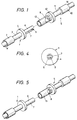
- Fig. 1 is a perspective view of a first embodiment of the invention;
- Fig. 2 is a cross-sectional view showing the terminals connected together;
- Fig. 3 is a cross-sectional view showing an initial stage of the insertion of the terminal;
- Fig. 4 is a side-elevational view of the male terminal;
- Fig. 5 is a perspective view of a second embodiment of the invention;
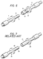
- Fig. 6 is a perspective view of a third embodiment of the invention; and
- Fig. 7 is a perspective view showing related art terminals.
- Preferred embodiments of the present invention will now be described in detail with reference to the drawings. Figs. 1-4 show a first embodiment of the present invention. For purposes of illustration, the invention will be described for use in, for example, a terminal used for a charging connector for an electric car. The charging connector includes charging connectors to be connected to the car and a charger, respectively. Terminals for allowing a relatively large current (for example, 30∼90A) are mounted within housings of the connectors. Each of the embodiments shown in the attached figures are for purposes of illustration and show only one of many possible pairs of male and female terminals for use in accordance with the invention, and the invention is not meant to be limited thereto.
- The
male terminal 1 is made of an electrically-conductive material, and has at one end, for example, its rear end portion, a larger-diameter portion 2 serving as a cord insertion portion for inserting a covered portion of a wire W thereinto. A smaller-diameter portion 3 is provided in communication with the larger-diameter portion 2, and a conductor portion of the wire W is inserted into the smaller-diameter portion 3. A flange 4 is formed in a continuous relationship with the smaller-diameter portion 3, and ashaft portion 6 insertable into afemale terminal 5 extends in one direction, for example, forwardly from the flange 4. Theshaft portion 6 is divided into a bifurcated configuration by an expandingslot 7, which is formed in theshaft portion 6 and extends axially from one end face, for example, a front end face thereof to a vicinity of the flange 4. In accordance with this embodiment of the invention, theshaft portion 6 can be resiliently deformed in an expansive direction, that is, in a diameter-increasing direction. Theshaft portion 6 has at its front end a tapered opening 9 flaring outwardly into a conical shape. A conical projection 8 (described later) on thefemale terminal 5 can be fitted in theopening 9. Theshaft portion 6 decreases in diameter progressively toward its front end. - In addition, the
female terminal 5, similar to themale terminal 1, is made of an electrically-conductive material, and has a larger-diameter portion 10, a smaller-diameter portion 11 and aflange 12. Extending in one direction, for example, forwardly from theflange 12 is an insertiontubular portion 13 into which theshaft portion 6 of themale terminal 1 is adapted to be inserted. The insertiontubular portion 13 is in the form of a hollow cylinder having a closed end, for example, a closed bottom and has a bore diameter slightly larger than an outer diameter of the front end portion of theshaft portion 6. The insertiontubular portion 13 has such an overall length such that when theshaft portion 6 is completely inserted into the insertiontubular portion 13 one end or edge, for example, a front end or edge of the insertiontubular portion 13 substantially abuts against the flange 4 of themale terminal 1. - In addition, the
projection 8 for forcibly expanding theshaft portion 6 is coaxially formed on and projected from the bottom surface of the insertiontubular portion 13. Theprojection 8 can be aligned with thetapered opening 9, and has a frusto-conical shape larger in size than the opening 9. Accordingly, when the male andfemale terminals projection 8 fits in theopening 9, so that theshaft portion 6 is expanded to a diameter substantially equal to the bore diameter of the insertiontubular portion 13 over substantially the entire length thereof. Therefore, theentire shaft portion 6 is held in contact with the bore surface of the insertiontubular portion 13 at a predetermined contact pressure. - In accordance with a first embodiment of the invention, and by fitting the two connector housings (not shown) together, the insertion of the
male terminal 1 into thefemale terminal 5 is achieved. In this embodiment, at an initial stage of the insertion operation, since the front end portion of theshaft portion 6 is smaller in diameter than the insertiontubular portion 13 as shown in Fig. 3, the insertion proceeds in such a manner that a predetermined gap is provided between theshaft portion 6 and the insertiontubular portion 13. Therefore, the operation of fitting of the two terminals together can be easily achieved, and the operating force required during the insertion is minimal. - When the front end of the
shaft portion 6 reaches the bottom of the insertiontubular portion 13, theprojection 8 becomes fitted in thetapered opening 9 of theshaft portion 6. At this point, the shaft portion is forcibly inserted, and theopening 9 is expanded so that theentire shaft portion 6 is brought into contact with the inner surface of the insertiontubular portion 13 at the predetermined contact pressure. - As discussed above, in accordance with the first embodiment of the invention, the insertion force required at an initial and intermediate stage of the insertion operation is minimal, and additional force is applied at a final stage of the insertion operation. Therefore, the insertion operation can be easily achieved and the operator can know when the terminal connecting operation is complete.
- Since the
shaft portion 6 is forcibly expanded by theprojection 8, an absolute contact between theshaft portion 6 and theinsertion tubular portion 13 can be achieved. Therefore, even if a resilient restoring force of theshaft portion 6 is decreased, the absolute contact can be ensured. Accordingly, this embodiment of the invention is particularly well-suited for a large current type connector. Furthermore, in the first embodiment of the invention, theprojection 8 is formed in a frustoconical shape, and therefore no directionality is needed, for example, with respect to a reference point, to insert theshaft portion 6. Accordingly, the terminal can be advantageously inserted without being aligned in any particular direction. - However, it is not always necessary that the
projection 8 be formed into a non-directional configuration as discussed above in accordance with the first embodiment. For example, in a second embodiment shown in Fig. 5, aprojection 8 is in the form of a flat plate, and accordingly, ashaft portion 6 is divided into two sections by an expandingslot 7. Theshaft portion 6 decreases in diameter progressively toward its front end, and theprojection 8, when engaged with the expandingslot 7, forcibly expands the front end portion of the shaft portion. As a result, theshaft portion 6 is brought into contact with the inner surface of theinsertion tubular portion 13 over substantially an entire length of theshaft portion 6. - Although in the first and second embodiments in accordance with the invention, the
projection 8 is on the bottom surface of theinsertion tubular portion 13, it is possible to provide the projection at any other suitable position in so far as the projection can expand theshaft portion 6 at the final stage of the insertion operation. For example, theprojection 8 may be provided on a side wall of theinsertion tubular portion 13 as in a third embodiment shown in Fig. 6. In accordance with this embodiment of the invention, theinsertion tubular portion 13 does not require the bottom surface. Further, the expandingslot 7 is not limited to a single expandingslot 7 as shown, rather, a plurality of expanding slots may be provided. In addition, a geometry of the shape of theprojection 8 can be modified to incorporate a variety of different shapes, for example, a pin-like projection of a circular cross-section. Furthermore, the projection orprojections 8 of any of the various shapes can be provided on the bottom surface or transversely on opposite portions of the side wall. Furthermore, although the present invention has been discussed above in an embodiment for use in the charging connector for an electric car, this embodiment is for purposes of illustration only, and it is within the scope of the invention to apply the invention to any type of connectors. - By these constructions, a minimal insertion force is required at the initial and intermediate stages of the insertion operation. Accordingly, a predetermined insertion force is applied only at the final stage. Therefore, the insertion operation is not difficult, and due to the increased insertion force required at the final stage of the insertion operation, the operator can know when the connection is completed. During the final stage, the projection forcibly expands the male terminal, so that the male terminal contacts the insertion tubular portion, thereby enhancing the reliability of the connection between the terminals.
- While advantageous embodiments have been chosen to illustrate the invention, it will be understood by those skilled in the art that various changes and modifications can be made therein without departing from the scope of the invention as defined in the appended claims.
Claims (7)
- A connector terminal comprising:a female terminal (5) having an insertion tubular portion (13) of a cylindrical shape;a male terminal (1) having a shaft portion (6) insertable into said female terminal (5), said shaft portion (6) having an insertion diameter less than the inner diameter of said insertion tubular portion (13) in a first position of the male terminal with respect to the female terminal and an expanded diameter substantially equal to said inner diameter in a second position of the male terminal with respect to the female terminal;said shaft portion (6) having at least one expanding slot (7) formed therein, so that said shaft portion can be deformed radially outward; andat least one projection (8) at a predetermined depth within said insertion tubular portion (13) for forcibly expanding said expanding slot (7) of said shaft portion to bring said shaft portion (6) into contact with an inner surface of said insertion tubular portion (13),characterized in that
said shaft portion (6) progressively decreases in diameter towards its front end, so that the entire shaft portion (6) contacts the insertion tubular portion (13) with a predetermined pressure. - The connector terminal according to claim 1, wherein said insertion tubular portion (13) has a closed end, the at least one projection (8) being disposed on the closed end.
- The connector terminal according to claim 1 or 2, wherein said insertion tubular portion (13) has an inner side wall, the at least one projection (8) being disposed on the inner side wall.
- The connector terminal according to claim 3, wherein a pair of projections (8) is disposed on opposed portions of the inner side wall.
- The connector terminal according to anyone of claims 1 or 2, wherein the at least one projection (8) comprises a truncated cone.
- The connector terminal according to anyone of claims 1 to 3, wherein the at least one projection (8) comprises a flat plate.
- The connector terminal according to anyone of claims 1 to 6, wherein the expanding slot (7) of the shaft portion (6) tapers at its end.
Applications Claiming Priority (2)
| Application Number | Priority Date | Filing Date | Title |
|---|---|---|---|
| JP85783/93 | 1993-03-18 | ||
| JP5085783A JP2924551B2 (en) | 1993-03-18 | 1993-03-18 | Terminal for connector |
Publications (2)
| Publication Number | Publication Date |
|---|---|
| EP0616388A1 EP0616388A1 (en) | 1994-09-21 |
| EP0616388B1 true EP0616388B1 (en) | 1997-07-02 |
Family
ID=13868487
Family Applications (1)
| Application Number | Title | Priority Date | Filing Date |
|---|---|---|---|
| EP94104204A Expired - Lifetime EP0616388B1 (en) | 1993-03-18 | 1994-03-17 | Connector terminal |
Country Status (4)
| Country | Link |
|---|---|
| US (1) | US5482480A (en) |
| EP (1) | EP0616388B1 (en) |
| JP (1) | JP2924551B2 (en) |
| DE (1) | DE69403980T2 (en) |
Families Citing this family (23)
| Publication number | Priority date | Publication date | Assignee | Title |
|---|---|---|---|---|
| JP2923518B2 (en) * | 1994-03-18 | 1999-07-26 | 矢崎総業株式会社 | Terminal for large current and processing method |
| US6454601B1 (en) | 2001-06-27 | 2002-09-24 | Andrew Corporation | Connector for coaxial cables |
| US6848922B2 (en) * | 2003-03-10 | 2005-02-01 | Hypertronics Corporation | Socket contact with integrally formed arc arresting portion |
| US7678461B2 (en) * | 2003-04-11 | 2010-03-16 | Treofan Germany Gmbh & Co. Kg | Biaxially oriented polypropylene film provided with a cold-seal adhesive coating and having excellent lubricating properties |
| US7690925B2 (en) * | 2005-02-24 | 2010-04-06 | Advanced Interconnections Corp. | Terminal assembly with pin-retaining socket |
| US7435102B2 (en) * | 2005-02-24 | 2008-10-14 | Advanced Interconnections Corporation | Interconnecting electrical devices |
| DE102006011116A1 (en) * | 2006-03-08 | 2007-09-20 | Ims Connector Systems Gmbh | Plug and mating connector for electrical contacting |
| JP5585809B2 (en) * | 2009-12-18 | 2014-09-10 | 株式会社山田精密製作所 | Connector terminal |
| CN101800368B (en) * | 2010-03-18 | 2014-05-07 | 钱秋英 | Internal expanding centre coupling |
| CN102237619B (en) * | 2010-04-30 | 2013-06-19 | 河南天海电器有限公司 | Conduction type charging connector for electric vehicle |
| DE202010010275U1 (en) | 2010-07-15 | 2011-12-20 | Weidmüller Interface GmbH & Co. KG | Electrical contact part |
| US8449311B2 (en) * | 2010-10-19 | 2013-05-28 | Ppc Broadband, Inc. | Locking audio plug |
| DE102010044091B4 (en) | 2010-11-18 | 2022-05-25 | Kiekert Aktiengesellschaft | Charging device for an electric vehicle |
| US8814587B2 (en) * | 2012-11-27 | 2014-08-26 | Goodrich Corporation | Low impedance equipment interface |
| US8926360B2 (en) | 2013-01-17 | 2015-01-06 | Cooper Technologies Company | Active cooling of electrical connectors |
| US9093764B2 (en) * | 2013-01-17 | 2015-07-28 | Cooper Technologies Company | Electrical connectors with force increase features |
| US9437952B2 (en) * | 2015-01-07 | 2016-09-06 | Appleton Grp Llc | Connector assembly having self-adjusting male and female connector elements |
| MA41371A (en) * | 2015-01-20 | 2017-11-28 | Zodiac Interconnect Uk Ltd | CONNECTOR EQUIPPED WITH A LOCKING PART AND PROCESS FOR IMPLEMENTING THE CONNECTOR |
| JP6422386B2 (en) * | 2015-03-31 | 2018-11-14 | ニッタ株式会社 | Connector device |
| JP6565654B2 (en) * | 2015-12-11 | 2019-08-28 | 日立金属株式会社 | Connector and terminal connection structure |
| JP7239316B2 (en) * | 2018-12-25 | 2023-03-14 | 矢崎総業株式会社 | Connector device and wire harness |
| TWM631187U (en) * | 2022-05-06 | 2022-08-21 | 健和興端子股份有限公司 | A crown spring connector |
| KR20240051722A (en) * | 2022-10-13 | 2024-04-22 | 현대자동차주식회사 | High voltage connector for vehicle |
Family Cites Families (12)
| Publication number | Priority date | Publication date | Assignee | Title |
|---|---|---|---|---|
| DE520869C (en) * | 1929-08-31 | 1931-03-16 | Joseph Junker | plug |
| CH190251A (en) * | 1936-10-13 | 1937-04-15 | Keller Jun Hans | Plug-in device for electrical lines. |
| CH256321A (en) * | 1946-01-14 | 1948-08-15 | Meuriot Paul Andre | Electrical connection device comprising a plug and a socket. |
| US3065450A (en) * | 1959-08-03 | 1962-11-20 | Burndy Corp | Separable connector |
| GB1120358A (en) * | 1967-05-08 | 1968-07-17 | Victor John Beddow | Improvements in or relating to electrical connectors |
| US3716817A (en) * | 1971-04-21 | 1973-02-13 | Mc Donnell Douglas Corp | Electrical connectors |
| US3894785A (en) * | 1972-04-18 | 1975-07-15 | Bunker Ramo | Connector |
| US4405195A (en) * | 1981-04-29 | 1983-09-20 | Amp Incorporated | Pin and socket connector |
| GB8801742D0 (en) * | 1988-01-27 | 1988-02-24 | Amp Great Britain | Pin & socket terminal |
| US4867697A (en) * | 1988-07-12 | 1989-09-19 | Al-Ray Development | Self-locking, two-part electrical connector employing receptacle with spring-biased wedge for expanding plug's blades |
| GB8817403D0 (en) * | 1988-07-21 | 1988-08-24 | Amp Gmbh | Electrical connector |
| US5197908A (en) * | 1991-11-29 | 1993-03-30 | Gunnar Nelson | Connector |
-
1993
- 1993-03-18 JP JP5085783A patent/JP2924551B2/en not_active Expired - Lifetime
-
1994
- 1994-03-16 US US08/213,583 patent/US5482480A/en not_active Expired - Fee Related
- 1994-03-17 DE DE69403980T patent/DE69403980T2/en not_active Expired - Fee Related
- 1994-03-17 EP EP94104204A patent/EP0616388B1/en not_active Expired - Lifetime
Also Published As
| Publication number | Publication date |
|---|---|
| US5482480A (en) | 1996-01-09 |
| JP2924551B2 (en) | 1999-07-26 |
| JPH06275333A (en) | 1994-09-30 |
| DE69403980T2 (en) | 1998-01-02 |
| EP0616388A1 (en) | 1994-09-21 |
| DE69403980D1 (en) | 1997-08-07 |
Similar Documents
| Publication | Publication Date | Title |
|---|---|---|
| EP0616388B1 (en) | Connector terminal | |
| US5611707A (en) | Microminiature coaxial connector which locks by snap-fastening | |
| US4688876A (en) | Connector for coaxial cable | |
| EP0616387B1 (en) | Connector terminal | |
| US3787796A (en) | Low cost sealed connector and method of making same | |
| EP0079120B1 (en) | Electrical connector | |
| EP0252601B1 (en) | Sealed connector having unitary molded housing | |
| US4280749A (en) | Socket and pin contacts for coaxial cable | |
| US4906212A (en) | Electrical pin and socket connector | |
| US5147230A (en) | Two piece electrical female terminal | |
| US4690481A (en) | Coaxial coupling | |
| US4701004A (en) | Retention clip for electrical contacts | |
| US5620345A (en) | High density pin and socket electrical connector | |
| JPH0782892B2 (en) | Drawer connector | |
| US3297979A (en) | Crimpable coaxial connector | |
| EP0935827B1 (en) | Contact with latch for contact retention and housing therefor | |
| EP0221952B1 (en) | Wire seal | |
| EP0566038B1 (en) | Electrical socket terminal | |
| JP2521141B2 (en) | Connector assembly and connector housing | |
| US3462726A (en) | Electrical connectors | |
| US5662503A (en) | Multi-wire locking system | |
| EP0562652B1 (en) | Electrical terminal | |
| US5487686A (en) | Pin terminal | |
| EP0568927B1 (en) | Electrical socket terminal | |
| US4810214A (en) | Electrical terminal and method of making same |
Legal Events
| Date | Code | Title | Description |
|---|---|---|---|
| PUAI | Public reference made under article 153(3) epc to a published international application that has entered the european phase |
Free format text: ORIGINAL CODE: 0009012 |
|
| AK | Designated contracting states |
Kind code of ref document: A1 Designated state(s): DE GB |
|
| 17P | Request for examination filed |
Effective date: 19950202 |
|
| 17Q | First examination report despatched |
Effective date: 19951218 |
|
| GRAG | Despatch of communication of intention to grant |
Free format text: ORIGINAL CODE: EPIDOS AGRA |
|
| GRAH | Despatch of communication of intention to grant a patent |
Free format text: ORIGINAL CODE: EPIDOS IGRA |
|
| GRAH | Despatch of communication of intention to grant a patent |
Free format text: ORIGINAL CODE: EPIDOS IGRA |
|
| GRAA | (expected) grant |
Free format text: ORIGINAL CODE: 0009210 |
|
| AK | Designated contracting states |
Kind code of ref document: B1 Designated state(s): DE GB |
|
| REF | Corresponds to: |
Ref document number: 69403980 Country of ref document: DE Date of ref document: 19970807 |
|
| PLBE | No opposition filed within time limit |
Free format text: ORIGINAL CODE: 0009261 |
|
| STAA | Information on the status of an ep patent application or granted ep patent |
Free format text: STATUS: NO OPPOSITION FILED WITHIN TIME LIMIT |
|
| 26N | No opposition filed | ||
| REG | Reference to a national code |
Ref country code: GB Ref legal event code: IF02 |
|
| PGFP | Annual fee paid to national office [announced via postgrant information from national office to epo] |
Ref country code: GB Payment date: 20020320 Year of fee payment: 9 |
|
| PGFP | Annual fee paid to national office [announced via postgrant information from national office to epo] |
Ref country code: DE Payment date: 20020327 Year of fee payment: 9 |
|
| PG25 | Lapsed in a contracting state [announced via postgrant information from national office to epo] |
Ref country code: GB Free format text: LAPSE BECAUSE OF NON-PAYMENT OF DUE FEES Effective date: 20030317 |
|
| PG25 | Lapsed in a contracting state [announced via postgrant information from national office to epo] |
Ref country code: DE Free format text: LAPSE BECAUSE OF NON-PAYMENT OF DUE FEES Effective date: 20031001 |
|
| GBPC | Gb: european patent ceased through non-payment of renewal fee |
Effective date: 20030317 |