EP0616218A1 - Dispositif micro-réacteur et système d'analyse de très petits échantillons utilisant ce dispositif - Google Patents
Dispositif micro-réacteur et système d'analyse de très petits échantillons utilisant ce dispositif Download PDFInfo
- Publication number
- EP0616218A1 EP0616218A1 EP94301820A EP94301820A EP0616218A1 EP 0616218 A1 EP0616218 A1 EP 0616218A1 EP 94301820 A EP94301820 A EP 94301820A EP 94301820 A EP94301820 A EP 94301820A EP 0616218 A1 EP0616218 A1 EP 0616218A1
- Authority
- EP
- European Patent Office
- Prior art keywords
- sample
- micro
- resevior
- reactive reagent
- reactor device
- Prior art date
- Legal status (The legal status is an assumption and is not a legal conclusion. Google has not performed a legal analysis and makes no representation as to the accuracy of the status listed.)
- Ceased
Links
Images


Classifications
-
- B—PERFORMING OPERATIONS; TRANSPORTING
- B01—PHYSICAL OR CHEMICAL PROCESSES OR APPARATUS IN GENERAL
- B01L—CHEMICAL OR PHYSICAL LABORATORY APPARATUS FOR GENERAL USE
- B01L3/00—Containers or dishes for laboratory use, e.g. laboratory glassware; Droppers
- B01L3/50—Containers for the purpose of retaining a material to be analysed, e.g. test tubes
- B01L3/502—Containers for the purpose of retaining a material to be analysed, e.g. test tubes with fluid transport, e.g. in multi-compartment structures
- B01L3/5027—Containers for the purpose of retaining a material to be analysed, e.g. test tubes with fluid transport, e.g. in multi-compartment structures by integrated microfluidic structures, i.e. dimensions of channels and chambers are such that surface tension forces are important, e.g. lab-on-a-chip
- B01L3/50273—Containers for the purpose of retaining a material to be analysed, e.g. test tubes with fluid transport, e.g. in multi-compartment structures by integrated microfluidic structures, i.e. dimensions of channels and chambers are such that surface tension forces are important, e.g. lab-on-a-chip characterised by the means or forces applied to move the fluids
-
- B—PERFORMING OPERATIONS; TRANSPORTING
- B01—PHYSICAL OR CHEMICAL PROCESSES OR APPARATUS IN GENERAL
- B01J—CHEMICAL OR PHYSICAL PROCESSES, e.g. CATALYSIS OR COLLOID CHEMISTRY; THEIR RELEVANT APPARATUS
- B01J19/00—Chemical, physical or physico-chemical processes in general; Their relevant apparatus
- B01J19/0093—Microreactors, e.g. miniaturised or microfabricated reactors
-
- G—PHYSICS
- G01—MEASURING; TESTING
- G01N—INVESTIGATING OR ANALYSING MATERIALS BY DETERMINING THEIR CHEMICAL OR PHYSICAL PROPERTIES
- G01N27/00—Investigating or analysing materials by the use of electric, electrochemical, or magnetic means
- G01N27/26—Investigating or analysing materials by the use of electric, electrochemical, or magnetic means by investigating electrochemical variables; by using electrolysis or electrophoresis
- G01N27/416—Systems
- G01N27/447—Systems using electrophoresis
- G01N27/44704—Details; Accessories
- G01N27/44743—Introducing samples
-
- G—PHYSICS
- G01—MEASURING; TESTING
- G01N—INVESTIGATING OR ANALYSING MATERIALS BY DETERMINING THEIR CHEMICAL OR PHYSICAL PROPERTIES
- G01N35/00—Automatic analysis not limited to methods or materials provided for in any single one of groups G01N1/00 - G01N33/00; Handling materials therefor
- G01N35/08—Automatic analysis not limited to methods or materials provided for in any single one of groups G01N1/00 - G01N33/00; Handling materials therefor using a stream of discrete samples flowing along a tube system, e.g. flow injection analysis
-
- B—PERFORMING OPERATIONS; TRANSPORTING
- B01—PHYSICAL OR CHEMICAL PROCESSES OR APPARATUS IN GENERAL
- B01J—CHEMICAL OR PHYSICAL PROCESSES, e.g. CATALYSIS OR COLLOID CHEMISTRY; THEIR RELEVANT APPARATUS
- B01J2219/00—Chemical, physical or physico-chemical processes in general; Their relevant apparatus
- B01J2219/00781—Aspects relating to microreactors
- B01J2219/00819—Materials of construction
- B01J2219/00824—Ceramic
- B01J2219/00828—Silicon wafers or plates
-
- B—PERFORMING OPERATIONS; TRANSPORTING
- B01—PHYSICAL OR CHEMICAL PROCESSES OR APPARATUS IN GENERAL
- B01J—CHEMICAL OR PHYSICAL PROCESSES, e.g. CATALYSIS OR COLLOID CHEMISTRY; THEIR RELEVANT APPARATUS
- B01J2219/00—Chemical, physical or physico-chemical processes in general; Their relevant apparatus
- B01J2219/00781—Aspects relating to microreactors
- B01J2219/00819—Materials of construction
- B01J2219/00831—Glass
-
- B—PERFORMING OPERATIONS; TRANSPORTING
- B01—PHYSICAL OR CHEMICAL PROCESSES OR APPARATUS IN GENERAL
- B01J—CHEMICAL OR PHYSICAL PROCESSES, e.g. CATALYSIS OR COLLOID CHEMISTRY; THEIR RELEVANT APPARATUS
- B01J2219/00—Chemical, physical or physico-chemical processes in general; Their relevant apparatus
- B01J2219/00781—Aspects relating to microreactors
- B01J2219/00889—Mixing
-
- B—PERFORMING OPERATIONS; TRANSPORTING
- B01—PHYSICAL OR CHEMICAL PROCESSES OR APPARATUS IN GENERAL
- B01L—CHEMICAL OR PHYSICAL LABORATORY APPARATUS FOR GENERAL USE
- B01L2300/00—Additional constructional details
- B01L2300/08—Geometry, shape and general structure
- B01L2300/0809—Geometry, shape and general structure rectangular shaped
- B01L2300/0816—Cards, e.g. flat sample carriers usually with flow in two horizontal directions
-
- B—PERFORMING OPERATIONS; TRANSPORTING
- B01—PHYSICAL OR CHEMICAL PROCESSES OR APPARATUS IN GENERAL
- B01L—CHEMICAL OR PHYSICAL LABORATORY APPARATUS FOR GENERAL USE
- B01L2300/00—Additional constructional details
- B01L2300/08—Geometry, shape and general structure
- B01L2300/0861—Configuration of multiple channels and/or chambers in a single devices
- B01L2300/0867—Multiple inlets and one sample wells, e.g. mixing, dilution
-
- B—PERFORMING OPERATIONS; TRANSPORTING
- B01—PHYSICAL OR CHEMICAL PROCESSES OR APPARATUS IN GENERAL
- B01L—CHEMICAL OR PHYSICAL LABORATORY APPARATUS FOR GENERAL USE
- B01L2300/00—Additional constructional details
- B01L2300/18—Means for temperature control
- B01L2300/1805—Conductive heating, heat from thermostatted solids is conducted to receptacles, e.g. heating plates, blocks
- B01L2300/1822—Conductive heating, heat from thermostatted solids is conducted to receptacles, e.g. heating plates, blocks using Peltier elements
-
- B—PERFORMING OPERATIONS; TRANSPORTING
- B01—PHYSICAL OR CHEMICAL PROCESSES OR APPARATUS IN GENERAL
- B01L—CHEMICAL OR PHYSICAL LABORATORY APPARATUS FOR GENERAL USE
- B01L2300/00—Additional constructional details
- B01L2300/18—Means for temperature control
- B01L2300/1894—Cooling means; Cryo cooling
-
- B—PERFORMING OPERATIONS; TRANSPORTING
- B01—PHYSICAL OR CHEMICAL PROCESSES OR APPARATUS IN GENERAL
- B01L—CHEMICAL OR PHYSICAL LABORATORY APPARATUS FOR GENERAL USE
- B01L2400/00—Moving or stopping fluids
- B01L2400/04—Moving fluids with specific forces or mechanical means
- B01L2400/0403—Moving fluids with specific forces or mechanical means specific forces
- B01L2400/0415—Moving fluids with specific forces or mechanical means specific forces electrical forces, e.g. electrokinetic
- B01L2400/0418—Moving fluids with specific forces or mechanical means specific forces electrical forces, e.g. electrokinetic electro-osmotic flow [EOF]
-
- B—PERFORMING OPERATIONS; TRANSPORTING
- B01—PHYSICAL OR CHEMICAL PROCESSES OR APPARATUS IN GENERAL
- B01L—CHEMICAL OR PHYSICAL LABORATORY APPARATUS FOR GENERAL USE
- B01L2400/00—Moving or stopping fluids
- B01L2400/04—Moving fluids with specific forces or mechanical means
- B01L2400/0403—Moving fluids with specific forces or mechanical means specific forces
- B01L2400/0415—Moving fluids with specific forces or mechanical means specific forces electrical forces, e.g. electrokinetic
- B01L2400/0421—Moving fluids with specific forces or mechanical means specific forces electrical forces, e.g. electrokinetic electrophoretic flow
-
- B—PERFORMING OPERATIONS; TRANSPORTING
- B01—PHYSICAL OR CHEMICAL PROCESSES OR APPARATUS IN GENERAL
- B01L—CHEMICAL OR PHYSICAL LABORATORY APPARATUS FOR GENERAL USE
- B01L2400/00—Moving or stopping fluids
- B01L2400/06—Valves, specific forms thereof
- B01L2400/0633—Valves, specific forms thereof with moving parts
-
- B—PERFORMING OPERATIONS; TRANSPORTING
- B01—PHYSICAL OR CHEMICAL PROCESSES OR APPARATUS IN GENERAL
- B01L—CHEMICAL OR PHYSICAL LABORATORY APPARATUS FOR GENERAL USE
- B01L2400/00—Moving or stopping fluids
- B01L2400/06—Valves, specific forms thereof
- B01L2400/0677—Valves, specific forms thereof phase change valves; Meltable, freezing, dissolvable plugs; Destructible barriers
-
- G—PHYSICS
- G01—MEASURING; TESTING
- G01N—INVESTIGATING OR ANALYSING MATERIALS BY DETERMINING THEIR CHEMICAL OR PHYSICAL PROPERTIES
- G01N30/00—Investigating or analysing materials by separation into components using adsorption, absorption or similar phenomena or using ion-exchange, e.g. chromatography or field flow fractionation
- G01N30/02—Column chromatography
- G01N2030/022—Column chromatography characterised by the kind of separation mechanism
- G01N2030/027—Liquid chromatography
-
- G—PHYSICS
- G01—MEASURING; TESTING
- G01N—INVESTIGATING OR ANALYSING MATERIALS BY DETERMINING THEIR CHEMICAL OR PHYSICAL PROPERTIES
- G01N30/00—Investigating or analysing materials by separation into components using adsorption, absorption or similar phenomena or using ion-exchange, e.g. chromatography or field flow fractionation
- G01N30/02—Column chromatography
- G01N30/04—Preparation or injection of sample to be analysed
- G01N30/16—Injection
- G01N2030/162—Injection electromigration
-
- G—PHYSICS
- G01—MEASURING; TESTING
- G01N—INVESTIGATING OR ANALYSING MATERIALS BY DETERMINING THEIR CHEMICAL OR PHYSICAL PROPERTIES
- G01N35/00—Automatic analysis not limited to methods or materials provided for in any single one of groups G01N1/00 - G01N33/00; Handling materials therefor
- G01N2035/00178—Special arrangements of analysers
- G01N2035/00237—Handling microquantities of analyte, e.g. microvalves, capillary networks
-
- G—PHYSICS
- G01—MEASURING; TESTING
- G01N—INVESTIGATING OR ANALYSING MATERIALS BY DETERMINING THEIR CHEMICAL OR PHYSICAL PROPERTIES
- G01N30/00—Investigating or analysing materials by separation into components using adsorption, absorption or similar phenomena or using ion-exchange, e.g. chromatography or field flow fractionation
- G01N30/02—Column chromatography
- G01N30/04—Preparation or injection of sample to be analysed
- G01N30/06—Preparation
-
- G—PHYSICS
- G01—MEASURING; TESTING
- G01N—INVESTIGATING OR ANALYSING MATERIALS BY DETERMINING THEIR CHEMICAL OR PHYSICAL PROPERTIES
- G01N30/00—Investigating or analysing materials by separation into components using adsorption, absorption or similar phenomena or using ion-exchange, e.g. chromatography or field flow fractionation
- G01N30/02—Column chromatography
- G01N30/04—Preparation or injection of sample to be analysed
- G01N30/24—Automatic injection systems
-
- Y—GENERAL TAGGING OF NEW TECHNOLOGICAL DEVELOPMENTS; GENERAL TAGGING OF CROSS-SECTIONAL TECHNOLOGIES SPANNING OVER SEVERAL SECTIONS OF THE IPC; TECHNICAL SUBJECTS COVERED BY FORMER USPC CROSS-REFERENCE ART COLLECTIONS [XRACs] AND DIGESTS
- Y10—TECHNICAL SUBJECTS COVERED BY FORMER USPC
- Y10S—TECHNICAL SUBJECTS COVERED BY FORMER USPC CROSS-REFERENCE ART COLLECTIONS [XRACs] AND DIGESTS
- Y10S436/00—Chemistry: analytical and immunological testing
- Y10S436/806—Electrical property or magnetic property
-
- Y—GENERAL TAGGING OF NEW TECHNOLOGICAL DEVELOPMENTS; GENERAL TAGGING OF CROSS-SECTIONAL TECHNOLOGIES SPANNING OVER SEVERAL SECTIONS OF THE IPC; TECHNICAL SUBJECTS COVERED BY FORMER USPC CROSS-REFERENCE ART COLLECTIONS [XRACs] AND DIGESTS
- Y10—TECHNICAL SUBJECTS COVERED BY FORMER USPC
- Y10T—TECHNICAL SUBJECTS COVERED BY FORMER US CLASSIFICATION
- Y10T436/00—Chemistry: analytical and immunological testing
- Y10T436/11—Automated chemical analysis
- Y10T436/117497—Automated chemical analysis with a continuously flowing sample or carrier stream
Definitions
- the present invention relates to a micro-reactor device in which a minute of sample material is made to react in a microscopic area and also to a minute sample analysis system which uses the micro-reactor device.
- a flow injection analysis is general wherein sample is introduced into reactive reagent and made to react therewith during flow of the sample liquid to be subjected to a concentration measurement by an optical detection method based on its absorbance, which details are shown, for example, in Analytical Chemistry, Vol. 50(1978), pp. 832A-846A or in Analytical Chemistry, Vol. 53(1981), pp. 20A-32A or in Analytica Chimica Acta, Vol. 78(1975), pp. 145-157.
- ⁇ p 8 ⁇ lQ/ ⁇ r4
- ⁇ denotes the viscosity of the liquid
- 1 denotes the length of the passage
- Q denotes flow quantity
- r denotes the radius of the passage.
- the pressure drop increases inversely proportional to the fourth power of the radius of the passage. For this reason, when a capillary as small as below 100 ⁇ m is used as the passage for the purpose of handling such a very small amount of sample as nanoliter level, the pressure drop becomes large, which involves another problem of withstanding pressure within the apparatus, that is, which requires a special measure of providing a pressure resistive property to the wall material of the passage and also to a coupling part between the passages to be taken.
- micro-reactor device wherein a very small amount of sample as minute as nanoliter level is made to react with reactive reagent as well as a minute sample analysis system which is a combination of the micro-reactor device as its pretreatment and a analyzing device suitable for analysis of a very small amount of sample composition such as a capillary electrophoresis device.
- transfer of sample and reactive reagent in a micro-reactor device is carried out on an electroosmotic flow.
- micro-reactor device is formed on a planar substrate having very narrow grooves.
- micro-reactor device is coupled via a quantitative measuring device with a capillary electrophoresis device.
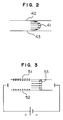
- Electroosmotic flow takes place when application of a voltage across a capillary tube causes electric double layers 51 and 52 formed on the internal surface of the tube to move in the same direction as an electric field established by the applied voltage, as shown in Fig. 3.
- a flow profile 53 is such a flat flow as shown in Fig. 3.
- sample diffusion is as small as several tenths of that in the case of laminar flow.
- a velocity u osm of the electro-osmotic flow is expressed by the following equation.
- u osm keE/z ⁇ c
- k denotes a constant
- e denotes charge quantity of the capillary tube per its unit surface
- E denotes applied voltage
- z denotes the number of charges in electrolyte
- ⁇ denotes the viscosity of solution
- c denotes the concentration of the electrolyte
- the electroosmotic flow depends on the applied voltage, the concentration of the electrolyte in the solution, the sign and the quantity of charges on the surface of the capillary tube, control of the quantity of solution to be transferred can be facilitated. Further, the pressure drop caused by the solution transfer is substantially zero.
- the capillary electrophoresis is an effective analyzing method having a high separation ability but requires a sample quantity to be as very small as nanoliter level.
- a quantitative measuring device between the capillary electrophoresis device and the micro-reactor device.
- a minute sample analysis system of Fig. 1 in accordance with the first embodiment of the present invention comprises a micro-reactor device 1, a quantitative measuring device 2, a analyzing device 3, and a controller 4.
- the micro-reactor device 1 includes a power supply 5 for liquid transfer; power change-over switch 6; passages 7a to 7g; sample quantity measurer 8; a solution resevior 9; a reactive reagent resevior 11; platinum electrodes 10, 12, 18 and 22; passage change-over switches 13, 14 and 15; an automatic sample injector 16, a sample resevior 17, a sample stage 19, a power supply 20 for sample introduction, a waste solution resevior 21, a reactor 23, and a constant-temperature heat resevior 24.
- the micro-reactor 1 functions to provide pre-treatment to cause reaction between sample and such reactive reagent as fluorescent reagent.
- the power supply for liquid transfer 5 which comprises a high voltage power supply having an output voltage of 0-30kV, applies a high voltage to between the platinum electrode 10 of the solution resevior 9 and the platinum electrode 28 of the waster solution resevior 27 of the quantitative measuring device 2 or to between the platinum electrode 12 of the reactive reagent resevior 11 and the platinum electrode 28 of the waste solution resevior 27 of the quantitative measuring device 2.
- a reactive reagent solution within the reactive reagent resevior 11, when the high voltage is applied to between the reactive reagent resevior 11 and the waste solution resevior 27 of the quantitative measuring device 2 is circulated in the form of an electroosmotic flow caused by the high voltage application through the passages 7b, 7c, 7d and 7e sequentially in this order.
- the flows of the above eluting and reactive reagent solutions can be controlled with use of the passage change-over switches 13, 14 and 15. Their flow rate can be easily set by controlling the applied voltage.
- the power change-over switch 6 acts to select the voltage application between the solution resevior 9 and the waste solution resevior 27 of the quantitative measuring device 2 or the voltage application between the reactive reagent resevior 11 and the waste solution resevior 27 of the quantitative measuring device 2.
- the applied voltage and the switching time By controlling the applied voltage and the switching time, the amount of reactive reagent introduced into the passages can be readily adjusted.
- each of the passages 7a to 7e was made up of a glass capillary tube (manufactured by GL Sciences company) having an inner diameter of 75 ⁇ m and an outer diameter of 375 ⁇ m. Further, the passage change-over switches 13, 14 and 15 may be replaced, for example, by a three-way valve.
- Sample introduction to the sample quantitative measurer 8 is carried out by means of the power supply 20 for sample introduction applying a high voltage to between the platinum electrode 18 of the sample resevior 17 placed on the sample stage 19 and the platinum electrode 22 of the waste solution resevior 21.
- the automatic sample injector 16 is used to insert a tip end of the passage 7f into the sample resevior 17 placed on the sample stage 19.
- the high voltage is applied to between the platinum electrode 18 of the sample resevior 17 and the platinum electrode 22 of the waste solution resevior 21 so that the sample solution within the sample resevior 17 flows in the form of an electroosmotic flow caused by the high voltage application through the passages 7f, 8 and 7g sequentially in this order.
- the amount of sample solution introduced can be set by the volume (internal volume) of the sample quantitative measurer 8.
- the tip end of the passage 7f and the platinum electrode 18 are assumed to be moved together by the sample stage with respect to the respective samples placed thereon.
- the amount of sample solution introduced can be easily controlled by adjusting the applied voltage and application time. More specifically, by suitably switching the passage change-over switches 14 and 15 so as to communicate with the passages 7f, 7d and 7g, the magnitude and application time of the high voltage applied from the power supply for sample introduction 20 to between the platinum electrodes 18 and 22 can be adjusted.
- the constant-temperature resevior 24 is kept at an optimum temperature for the reaction.
- the quantitative measuring device 2 includes a passage change-over unit 25, the reacted sample quantitative measurer 26, the waste reactive solution resevior 27 and the platinum electrode 28; and functions to perform quantitative measuring operation over the reaction sample subjected to the reaction at the micro-reactor device 1 and then to supply the quantitative-measured sample to the analyzing device 3.
- the analyzing device 3 as a capillary electro-phoresis device in the present embodiment includes a capillary tube 29, a buffer resevior 30, a buffer waste solution resevior 33, platinum electrodes 31 and 33, a power supply for analysis 32, an optical detector 35 and a recorder 36.
- used as the capillary tube 29 was a glass capillary tube (manufactured by GL Sciences company) having an inner diameter of 75 ⁇ m and an outer diameter of 375 ⁇ m.
- the power supply for analysis 32 is used to apply a high voltage to between the platinum electrode 31 of the buffer resevior 30 and the platinum electrode 34 of the buffer waste solution resevior 33 to thereby provide preliminary electrophoresis to solution and to keep the solution in such an electrophoresis enable state.
- the reacted sample within the reacted sample quantitative measurer 26 of the quantitative measuring device 2 is introduced into the capillary tube 29 for electrophoresis. Components of the reacted sample separated within the capillary tube 29 by the electrophoresis are detected by the optical detector 35 and the migration times and concentration values for the respective detected components are sent to the recorder 36 to be recorded therein.
- capillary electrophoresis device has been used as the analyzing device in the present embodiment, a high performance liquid chromatography device may be employed in place of the capillary electrophoresis device while not compelling great modification in the device arrangement.
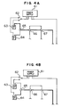
- a power supply 61 for sample introduction is operated to apply a high voltage to a solution resevior 63, in which case a power change-over switch 62 operatively connected with a passage change-over switch 65 is set at such a position as to form a thick solid line passage shown in Fig. 4A.
- the power change-over switch 62 is switched to the other position so that, at the same time that a high voltage is applied to a reactive reagent resevior 64, the passage change-over switch 65 operatively connected with the power change-over switch 62 is also switched, whereby such a path as shown by a thick solid line in Fig.
- passage change-over switches 66 and 67 are operatively connected with the power supply for sample introduction 61, so that, when it is desired to supply the solution by means of the power supply for sample introduction 61, such a path as shown by a thick solid line in Fig. 4B is formed.
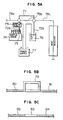
- an automatic sample injector 73 is operated to insert a tip end of a passage 72a into a sample resevior 75 placed on a sample stage 74, and then a power supply 77 for sample introduction is operated to apply a high voltage to between the sample and waste solution reseviors 75 and 76.
- Application of the high voltage to the sample and waster solution reseviors 75 and 76 causes generation of an electroosmotic flow, whereby the sample solution within the sample resevior 75 flows through passages 72a, 71 and 72b sequentially in this order.
- the reactive reagent is also being supplied through passages 78a, 78b and 87c sequentially in this order.
- the reactive reagents 80 and 81 there are reactive reagents 80 and 81 at upstream and downstream or front and rear ends of a sample 79, that is, the sample is put in a sandwiched relation between the reactive reagents 80 and 81.
- supply of the solution by the electroosmotic flow causes the sample and reagents to flow while reacting with one another as shown in Fig. 5C.
- the sample 83 is put in the sandwiched relation between the reactive reagents 82 and 84 to be efficiently mixed with the reactive reagents 82 and 84 at the front and rear ends of the sample 83 through diffusion, the efficient reaction can be realized.
- the passage change-over switches 66 and 67 when it is desired to supply the solution by means of the operation of the power supply for sample introduction 61, are set at such positions as to form the path shown by the thick solid line in Fig. 4B.
- power change-over to the power supply for sample introduction 77 causes change-over of the passage change-over switches 66 and 67, with the result that such a path as shown by a thick solid line in Fig. 5A is formed.
- a power supply for analysis 95 is operated to apply a high voltage to between a buffer resevior 94 and a buffer waste solution resevior 96.
- the reacted sample supplied from the micro-reactor device 1 is filled within a reacted sample quantitative measurer 92 of a passage change-over switch 91.
- the passage change-over switch 91 is switched so that the reacted sample is introduced into a capillary tube 93 for electrophoresis as shown by a thick solid line in Fig. 6B.
- the passage change-over switch 91 is operatively connected with an optical detector 97 and a recorder 98 so that change-over of the switch 91 causes simultaneous analysis and recording of the sample thereat.
- the transfer of the sample and reactive reagent is based on electroosmotic flow in the present embodiment, the diffusion of the sample and reactive reagent is as very small as several tenths of that in the case of laminar flow. Further, substantially no pressure drop can be caused by the solution transfer and the reaction between a very small amount of sample and reactive reagent can be efficiently carried out within such a capillary tube as small as below 100 ⁇ m in inner diameter.
- micro-reactor device is connected via the measuring device to the capillary electrophoresis device, a very small amount of sample can be accurately introduced into the capillary electro-phoresis device and on-line analysis including reaction of the very small amount of sample with the reagent and separation of sample composition can be performed without involving any dilution and loss of the sample.
- the illustrated micro-reactor device of the second embodiment includes power supplies 101 and 102, a reactive reagent resevior 103, waste solution reseviors 104 and 105, sample reseviors 106a to 106d, passages 107a to 107f, passage change-over switches 108, 109, 110, 111, 112, 113 and 114, a measurer 115, a light source 116, a detector 117, and a controller 118.
- the micro-reactor device except the power supplies is formed on a planar plate insulator such as a glass plate, a single crystal silicone substrate, etc.
- the power supply 102 having a high output voltage of 0-30kV is used to apply a high voltage to between an electrode of the reactive reagent resevior 103 and an electrode of the waste solution resevior 104.
- the power supply 101 is used to apply a high voltage to between electrodes of the sample reseviors 106a to 106d and an electrode of the waste solution resevior 105.
- the electroosmotic flow generated by the high voltage application causes the reactive reagent within the reactive reagent resevior 103 to flow through the passages 107a, 107b and 107c sequentially in this order.
- the electroosmotic flow generated by the high voltage application causes the sample solution.within the sample reseviors 106a to 106d to flow through the passages 107d, 107e, 107b and 107f sequentially in this order.
- the micro-reactor device is designed for selective application of 4 samples.
- the flows of the above reactive reagent and sample can be switchingly controlled by means of the passage change-over switches 108, 109, 110 and 111 controlled based on a signal issued from the controller 118.
- the flow rate can be easily set by adjusting the applied voltage or time of the power supplies 101 and 102 on the basis of a signal from the controller 118.
- the reaction of the micro-reactor device of the present embodiment is carried out in the following sequence.
- the reactive reagent is introduced into the passages 107a, 107b and 107c, at which time the passage change-over switches 110 and 111-114 are operated to close the path and to stop the flowing of the sample.
- a high voltage is applied to between the electrode of the reactive reagent resevior 103 and the electrode of the waste solution resevior 104 so that the electroosmotic flow generated by the high voltage application causes the reactive reagent within the reactive reagent resevior 103 to flow through the passages 107a, 107b and 107c sequentially in this order.
- the power supply 101 for sample injection is operated to apply a high voltage to between the electrode of the sample resevior 106a and the electrode of the waste solution resevior 105.
- the passage change-over switches 110 and 111 are first operated to open the path. After that, a high voltage is applied to between the electrode of the sample resevior 106a and the electrode of the waste solution resevior 105 so that the electroosmotic flow generated by the high voltage application causes the sample within the sample resevior 106a to flow through the passages 107d, 107e, 107b and 107f sequentially in this order.
- the amount of sample introduced can be set by the capacity of the passage 107b functioning also as a sample quantitative measurer. Even with respect to the sample solutions of the sample reseviors 106b to 106d, the sample introduction can be similarly controlled by the passage change-over switches 112, 113 and 110.
- the passage change-over switches 110 and 111 are operated to close the path and to stop the flowing of the sample and subsequently the passage change-over switches 108 and 109 are operated to open the reactive reagent path.
- the electroosmotic flow generated by the high voltage application causes the sample and reactive reagent to flow through the passages 107b and 107c while reacting with each other.
- the measurer 115 has a high light transmittance and especially in case of absorbance change measurement, the measurer passage is provided thereon with a light reflecting layer to prolong its light path length. Further, when it is desired to measure a multiplicity of samples, this can be easily realized by sequentially operating the passage change-over switches 111, 112, 113 and 114 in the similar procedure to the above.
- the aforementioned operations are controlled by the controller 118 and thus when the applied voltage and time, passage change-over timing, etc. are controlled in accordance with a computer program, the operation control can be realized with use of a single switch.
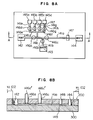
- Fig. 8A shows a passage arrangement of the micro-reactor device.
- the passages of the micro-reactor device are formed by first providing very narrow grooves and small through holes in such a planar substrate as a glass or silicon substrate, overlapping another planar substrate on the former substrate, and then joining the substrates together by fusion bonding.
- passages 141a to 141h are defined by the very narrow grooves while a reactive reagent resevior 142, waste solution reseviors 143 and 144, and sample reseviors 145a to 145d are defined by the small through holes.
- passage change-over switches 146a to 146g may function to perform their switching operation by mechanically opening or closing the small through holes for passage change-over or by partially freezing or unfreezing the passages 141a to 141h.
- Fig. 8B shows a side cross-sectional view of the micro-reactor device of Fig. 8A as viewed from a passage position A-A shown by arrows.
- reference numeral 200 denotes a planar substrate which is provided in its one surface with very small grooves and small through holes.
- Numeral 300 denotes a planar substrate overlapped on the substrate 200.
- the passage change-over switches 146a and 146c are provided therein with members 146a' and 146c' which function as stop plugs and as already explained above, which are controlled by the controller 118 to open or close the associated passages.
- the reactive reagent resevior 142, waste solution reseviors 143 and 144, and sample reseviors 145a to 145d are provided on their walls with electrodes for providing electroosmotic flow (only two of which electrodes for the reactive reagent resevior 142 and waste solution resevior 144 being illustrated in the drawing).
- the reactive reagent resevior 142, waste solution reseviors 143 and 144, and sample reseviors 145a to 145d are provided in the same planar substrate in the present embodiment, the need for connecting the reactive reagent resevior, waste solution reseviors and sample reseviors through connectors as in the prior art can be eliminated and thus a leakage problem and the need for interconnections in very small areas can be removed. Further, since only the controller, high voltage power supplies and optical detector are provided as external devices, the entire apparatus can be made easily small in size.
- the reactive reagent resevior 142, waste solution reseviors 143 and 144, and sample reseviors 145a to 145d are disposed as externally faced, the introduction and the exchange of the reactive reagent and sample, the washing, and the waste solution removing can be facilitated.
- the amounts of reactive reagent and sample used depend on the sizes of the reactive reagent resevior and sample reseviors. For this reason, minute amount of sample as very small as microliter level can be exchanged without any loss by making the diameter of the small through holes for the reactive reagent resevior and sample reseviors to be below 5000 ⁇ m.
- a measurer 147 includes a light transmittable part 148 made of silica glass having a high light transmittance and a light reflecting layer 149.
- the light reflecting layer 149 is made preferably of such material having an excellent reflectance as platinum or rhodium. When it is desirable to provide the measurer in the form of a light transmission type, the reflecting layer 149 can be omitted.
- Fig. 9A shows a part of the passage change-over means which includes sample passages 151a and 151b, reactive reagent passages 152a to 152c and passage change-over switches 153 and 154.
- the passage 152b functions also as a sample quantitative measurer.
- the sample quantitative measurement and reaction can be carried out by closing the passage change-over switches 153 and 154 to introduce the sample into the passage 152b functioning also as the sample quantitative measurer.
- Fig. 9B shows a side cross-sectional view of a part of a passage change-over means which includes Peltier elements 158, 159, 160 and 161 which are made in planar substrates 156 and 157 as opposed to each other with a passage 155 disposed therebetween. Passage change-over can be effected by cooling the solution in the passage to -15°C or less by means of the Peltier elements 158, 159, 160 and 161 to close the passage 155.
- the passage change-over in microscopic areas can be facilitated with a simple arrangement because the opening and closing of the passages is carried out by freezing and unfreezing the solution in the passages.
Applications Claiming Priority (2)
| Application Number | Priority Date | Filing Date | Title |
|---|---|---|---|
| JP5055327A JPH06265447A (ja) | 1993-03-16 | 1993-03-16 | 微量反応装置およびこれを使用する微量成分測定装置 |
| JP55327/93 | 1993-03-16 |
Publications (1)
| Publication Number | Publication Date |
|---|---|
| EP0616218A1 true EP0616218A1 (fr) | 1994-09-21 |
Family
ID=12995448
Family Applications (1)
| Application Number | Title | Priority Date | Filing Date |
|---|---|---|---|
| EP94301820A Ceased EP0616218A1 (fr) | 1993-03-16 | 1994-03-15 | Dispositif micro-réacteur et système d'analyse de très petits échantillons utilisant ce dispositif |
Country Status (3)
| Country | Link |
|---|---|
| US (1) | US5480614A (fr) |
| EP (1) | EP0616218A1 (fr) |
| JP (1) | JPH06265447A (fr) |
Cited By (31)
| Publication number | Priority date | Publication date | Assignee | Title |
|---|---|---|---|---|
| WO1997021090A1 (fr) * | 1995-12-05 | 1997-06-12 | Gamera Bioscience | Dispositifs et procedes d'utilisation de l'acceleration centripete pour commander le deplacement de liquides dans le traitement de laboratoire automatise |
| EP0815940A2 (fr) * | 1996-06-28 | 1998-01-07 | Caliper Technologies Corporation | Pipette électrocinétique, et moyens de compensation d'effets électrophorétiques |
| WO1998005424A1 (fr) * | 1996-08-02 | 1998-02-12 | Caliper Technologies Corporation | Dispositif analytique et procede correspondant |
| WO1998052691A1 (fr) * | 1997-05-16 | 1998-11-26 | Alberta Research Council | Systeme microfluidique et ses utilisations |
| EP0883442A1 (fr) * | 1995-06-06 | 1998-12-16 | Sarnoff Corporation | Pompage electrocinetique |
| EP0892678A1 (fr) * | 1996-04-09 | 1999-01-27 | Sarnoff Corporation | Systeme de dosage |
| WO1999039005A1 (fr) * | 1998-01-29 | 1999-08-05 | University Of Pittsburgh | Procede de thermocyclage rapide destine a l'analyse d'echantillons |
| EP0972082A1 (fr) * | 1997-04-04 | 2000-01-19 | Caliper Technologies Corporation | Analyseurs biochimiques fonctionnant en boucle fermee |
| EP0988529A1 (fr) * | 1997-04-25 | 2000-03-29 | Caliper Technologies Corporation | Dispositifs microfluidiques a geometrie de canaux amelioree |
| EP1020014A1 (fr) * | 1997-09-25 | 2000-07-19 | Caliper Technologies Corporation | Micropompe |
| US6143248A (en) * | 1996-08-12 | 2000-11-07 | Gamera Bioscience Corp. | Capillary microvalve |
| US6143247A (en) * | 1996-12-20 | 2000-11-07 | Gamera Bioscience Inc. | Affinity binding-based system for detecting particulates in a fluid |
| WO2000066995A2 (fr) * | 1999-04-29 | 2000-11-09 | Genome Therapeutics Corporation | Dispositif permettant de traiter rapidement un echantillon d'adn par manipulation de liquide, thermocyclage et purification |
| WO2001012327A1 (fr) * | 1999-08-12 | 2001-02-22 | Ut-Battelle, Llc | Dispositifs a microfluides pour la manipulation controlee de petits volumes |
| US6302134B1 (en) | 1997-05-23 | 2001-10-16 | Tecan Boston | Device and method for using centripetal acceleration to device fluid movement on a microfluidics system |
| EP1159605A1 (fr) * | 1999-02-02 | 2001-12-05 | Caliper Technologies Corporation | Procedes, dispositifs et systemes de caracterisation de proteines |
| US6338820B1 (en) | 1997-08-15 | 2002-01-15 | Alexion Pharmaceuticals, Inc. | Apparatus for performing assays at reaction sites |
| AU747505B2 (en) * | 1997-04-25 | 2002-05-16 | Caliper Life Sciences, Inc. | Microfluidic devices incorporating improved channel geometries |
| GB2379018A (en) * | 2001-08-10 | 2003-02-26 | Univ Hull | Monitoring chemical reactions in a microreactor |
| WO2003055605A1 (fr) * | 2001-12-21 | 2003-07-10 | Siemens Aktiengesellschaft | Dispositif servant a separer un constituant d'un fluide |
| US6620625B2 (en) | 2000-01-06 | 2003-09-16 | Caliper Technologies Corp. | Ultra high throughput sampling and analysis systems and methods |
| US6632399B1 (en) | 1998-05-22 | 2003-10-14 | Tecan Trading Ag | Devices and methods for using centripetal acceleration to drive fluid movement in a microfluidics system for performing biological fluid assays |
| US6632619B1 (en) | 1997-05-16 | 2003-10-14 | The Governors Of The University Of Alberta | Microfluidic system and methods of use |
| US6709869B2 (en) | 1995-12-18 | 2004-03-23 | Tecan Trading Ag | Devices and methods for using centripetal acceleration to drive fluid movement in a microfluidics system |
| US6811668B1 (en) | 1999-06-22 | 2004-11-02 | Caliper Life Sciences, Inc. | Apparatus for the operation of a microfluidic device |
| WO2005001435A2 (fr) * | 2002-08-26 | 2005-01-06 | The Regents Of The University Of California | Systeme de regulation autonome d'agents biologiques |
| FR2864625A1 (fr) * | 2003-12-24 | 2005-07-01 | Rhodia Chimie Sa | Procede et installation de determination des caracteristiques representatives d'une transformation physique et/ou chimique intervenant dans un micro-reacteur |
| EP1577010A3 (fr) * | 1995-12-05 | 2005-11-16 | Tecan Trading AG | Plate-forme à microsystème et son utilisage |
| EP1739418A1 (fr) * | 2004-04-21 | 2007-01-03 | Toray Industries, Inc. | Support pour labo-sur-puce |
| US7795006B2 (en) | 2003-05-19 | 2010-09-14 | Toray Industries, Inc. | Support having selectively bonding substance fixed thereto |
| EP2259053A3 (fr) * | 1997-04-25 | 2012-11-14 | Caliper Life Sciences, Inc. | Dispositifs microfluidiques a geométrie de canaux ameliorée |
Families Citing this family (101)
| Publication number | Priority date | Publication date | Assignee | Title |
|---|---|---|---|---|
| US5935401A (en) * | 1996-09-18 | 1999-08-10 | Aclara Biosciences | Surface modified electrophoretic chambers |
| EP0620432B1 (fr) * | 1993-04-15 | 2004-08-25 | Zeptosens AG | Méthode pour contrôler l'introduction d'un échantillon en séparation par micro colonnes et appareil d'échantillonage |
| SE513881C2 (sv) * | 1994-01-10 | 2000-11-20 | Boule Medical Ab | Förfarande och anordning för analys av vätskeprover |
| US20050042149A1 (en) * | 1994-04-01 | 2005-02-24 | Integrated Chemical Synthesizers, Inc. | Nanoscale chemical synthesis |
| US5580523A (en) * | 1994-04-01 | 1996-12-03 | Bard; Allen J. | Integrated chemical synthesizers |
| US5632876A (en) * | 1995-06-06 | 1997-05-27 | David Sarnoff Research Center, Inc. | Apparatus and methods for controlling fluid flow in microchannels |
| US5603351A (en) | 1995-06-07 | 1997-02-18 | David Sarnoff Research Center, Inc. | Method and system for inhibiting cross-contamination in fluids of combinatorial chemistry device |
| US5985119A (en) * | 1994-11-10 | 1999-11-16 | Sarnoff Corporation | Electrokinetic pumping |
| EP0791238B1 (fr) * | 1994-11-10 | 2004-09-22 | Orchid BioSciences, Inc. | Systeme de distribution de liquide |
| US5585069A (en) * | 1994-11-10 | 1996-12-17 | David Sarnoff Research Center, Inc. | Partitioned microelectronic and fluidic device array for clinical diagnostics and chemical synthesis |
| US5747020A (en) * | 1995-05-15 | 1998-05-05 | Pioneer Hi-Bred International, Inc. | Bacterial treatment for silage |
| US6120665A (en) * | 1995-06-07 | 2000-09-19 | Chiang; William Yat Chung | Electrokinetic pumping |
| US6454945B1 (en) * | 1995-06-16 | 2002-09-24 | University Of Washington | Microfabricated devices and methods |
| US5716852A (en) * | 1996-03-29 | 1998-02-10 | University Of Washington | Microfabricated diffusion-based chemical sensor |
| EP0839318B1 (fr) * | 1995-06-16 | 2003-05-07 | University of Washington | Procede et dispositif miniaturise d'extraction differentielle |
| US5948684A (en) | 1997-03-31 | 1999-09-07 | University Of Washington | Simultaneous analyte determination and reference balancing in reference T-sensor devices |
| US6541213B1 (en) * | 1996-03-29 | 2003-04-01 | University Of Washington | Microscale diffusion immunoassay |
| US20030211507A1 (en) * | 1996-03-29 | 2003-11-13 | Anson Hatch | Microscale diffusion immunoassay in hydrogels |
| US6033544A (en) * | 1996-10-11 | 2000-03-07 | Sarnoff Corporation | Liquid distribution system |
| US5840256A (en) * | 1996-04-09 | 1998-11-24 | David Sarnoff Research Center Inc. | Plate for reaction system |
| EP0910474B1 (fr) * | 1996-06-14 | 2004-03-24 | University of Washington | Procede d'extraction differentielle a absorption amelioree |
| US5800690A (en) * | 1996-07-03 | 1998-09-01 | Caliper Technologies Corporation | Variable control of electroosmotic and/or electrophoretic forces within a fluid-containing structure via electrical forces |
| US6110343A (en) * | 1996-10-04 | 2000-08-29 | Lockheed Martin Energy Research Corporation | Material transport method and apparatus |
| US6447727B1 (en) * | 1996-11-19 | 2002-09-10 | Caliper Technologies Corp. | Microfluidic systems |
| US6465257B1 (en) | 1996-11-19 | 2002-10-15 | Caliper Technologies Corp. | Microfluidic systems |
| WO1998046986A1 (fr) * | 1997-04-15 | 1998-10-22 | Sarnoff Corporation | Procede de translocation de microparticules dans un dispositif microfabrique |
| US6190616B1 (en) * | 1997-09-11 | 2001-02-20 | Molecular Dynamics, Inc. | Capillary valve, connector, and router |
| JP2001518624A (ja) | 1997-09-26 | 2001-10-16 | ユニバーシティ・オブ・ワシントン | 同時の粒子分離および化学反応 |
| US5976472A (en) * | 1997-10-15 | 1999-11-02 | Eastman Kodak Company | Integrated micro-ceramic chemical plant with insertable catalytic reaction chambers |
| US5965092A (en) * | 1997-10-15 | 1999-10-12 | Eastman Kodak Company | Integrated micro-ceramic chemical plant with insertable micro-filters |
| US5961930A (en) * | 1997-10-15 | 1999-10-05 | Eastman Kodak Company | Integrated micro-ceramic chemical plant with insertable reaction chambers and micro-filters |
| US6685809B1 (en) * | 1999-02-04 | 2004-02-03 | Ut-Battelle, Llc | Methods for forming small-volume electrical contacts and material manipulations with fluidic microchannels |
| US6117396A (en) * | 1998-02-18 | 2000-09-12 | Orchid Biocomputer, Inc. | Device for delivering defined volumes |
| US6979424B2 (en) | 1998-03-17 | 2005-12-27 | Cepheid | Integrated sample analysis device |
| US6123798A (en) * | 1998-05-06 | 2000-09-26 | Caliper Technologies Corp. | Methods of fabricating polymeric structures incorporating microscale fluidic elements |
| US6830729B1 (en) | 1998-05-18 | 2004-12-14 | University Of Washington | Sample analysis instrument |
| WO1999060397A1 (fr) | 1998-05-18 | 1999-11-25 | University Of Washington | Cartouche d'analyse liquide |
| US6274089B1 (en) | 1998-06-08 | 2001-08-14 | Caliper Technologies Corp. | Microfluidic devices, systems and methods for performing integrated reactions and separations |
| EP1084391A4 (fr) * | 1998-06-08 | 2006-06-14 | Caliper Life Sciences Inc | Dispositifs microfluidiques, systemes et procedes pour realiser des reactions et des separations integrees |
| US6077660A (en) * | 1998-06-10 | 2000-06-20 | Abbott Laboratories | Diagnostic assay requiring a small sample of biological fluid |
| US6375901B1 (en) | 1998-06-29 | 2002-04-23 | Agilent Technologies, Inc. | Chemico-mechanical microvalve and devices comprising the same |
| US6572830B1 (en) | 1998-10-09 | 2003-06-03 | Motorola, Inc. | Integrated multilayered microfludic devices and methods for making the same |
| US6592696B1 (en) | 1998-10-09 | 2003-07-15 | Motorola, Inc. | Method for fabricating a multilayered structure and the structures formed by the method |
| US6413780B1 (en) | 1998-10-14 | 2002-07-02 | Abbott Laboratories | Structure and method for performing a determination of an item of interest in a sample |
| EP0999443A3 (fr) * | 1998-11-02 | 2002-09-18 | The Institute of Physical and Chemical Research | Appareil d'électrophorèse capillaire, plaquette-échantillon, et procédé d'injection d'échantillon |
| US6485690B1 (en) | 1999-05-27 | 2002-11-26 | Orchid Biosciences, Inc. | Multiple fluid sample processor and system |
| WO2001051918A1 (fr) | 2000-01-12 | 2001-07-19 | Ut-Battelle, Llc | Dispositif microfluidique et procede de concentration, de segmentation et de distribution d'un ecoulement fluidique |
| DE10017791A1 (de) * | 2000-04-10 | 2001-10-11 | Basf Ag | Verfahren und Vorrichtung zur Mikrodosierung kleinster Flüssigkeitsmengen für Biopolymerarrays |
| US6733244B1 (en) * | 2000-12-20 | 2004-05-11 | University Of Arkansas, N.A. | Microfluidics and small volume mixing based on redox magnetohydrodynamics methods |
| US6783992B2 (en) | 2001-01-03 | 2004-08-31 | Agilent Technologies, Inc. | Methods and using chemico-mechanical microvalve devices for the selective separation of components from multi-component fluid samples |
| US6729352B2 (en) | 2001-06-07 | 2004-05-04 | Nanostream, Inc. | Microfluidic synthesis devices and methods |
| EP1436426A4 (fr) * | 2001-10-24 | 2005-11-02 | Singulex Inc | Procedes destines a detecter des haplotypes genetiques par interaction avec des sondes |
| US7010964B2 (en) * | 2002-10-31 | 2006-03-14 | Nanostream, Inc. | Pressurized microfluidic devices with optical detection regions |
| US10533998B2 (en) | 2008-07-18 | 2020-01-14 | Bio-Rad Laboratories, Inc. | Enzyme quantification |
| GB0307403D0 (en) * | 2003-03-31 | 2003-05-07 | Medical Res Council | Selection by compartmentalised screening |
| GB0307428D0 (en) * | 2003-03-31 | 2003-05-07 | Medical Res Council | Compartmentalised combinatorial chemistry |
| US20060078893A1 (en) * | 2004-10-12 | 2006-04-13 | Medical Research Council | Compartmentalised combinatorial chemistry by microfluidic control |
| US20090088982A1 (en) * | 2003-07-31 | 2009-04-02 | Fukushima Noelle H | Co-detection of single polypeptide and polynucleotide molecules |
| US20080021674A1 (en) * | 2003-09-30 | 2008-01-24 | Robert Puskas | Methods for Enhancing the Analysis of Particle Detection |
| US20050221339A1 (en) * | 2004-03-31 | 2005-10-06 | Medical Research Council Harvard University | Compartmentalised screening by microfluidic control |
| WO2006036592A1 (fr) * | 2004-09-23 | 2006-04-06 | University Of Washington | Immuno-essai de diffusion a micro-echelle utilisant des reactifs polyvalents |
| US9040305B2 (en) * | 2004-09-28 | 2015-05-26 | Singulex, Inc. | Method of analysis for determining a specific protein in blood samples using fluorescence spectrometry |
| WO2006036182A2 (fr) * | 2004-09-28 | 2006-04-06 | Singulex, Inc. | Systeme et methode d'analyse d'echantillons |
| US8685711B2 (en) * | 2004-09-28 | 2014-04-01 | Singulex, Inc. | Methods and compositions for highly sensitive detection of molecules |
| US7572640B2 (en) * | 2004-09-28 | 2009-08-11 | Singulex, Inc. | Method for highly sensitive detection of single protein molecules labeled with fluorescent moieties |
| US7968287B2 (en) * | 2004-10-08 | 2011-06-28 | Medical Research Council Harvard University | In vitro evolution in microfluidic systems |
| EP2364774A3 (fr) | 2006-01-11 | 2014-06-04 | Raindance Technologies, Inc. | Dispositifs Microfluidiques Et Leurs Procédés D'utilisation Dans La Formation Et Le Contrôle De Nanoréacteurs |
| US7838250B1 (en) | 2006-04-04 | 2010-11-23 | Singulex, Inc. | Highly sensitive system and methods for analysis of troponin |
| EP3156799B1 (fr) | 2006-04-04 | 2024-01-24 | Novilux, LLC | Analyseur et procédé hautement sensible de détection d'analytes |
| EP3495822B1 (fr) | 2006-04-04 | 2023-12-20 | Novilux, LLC | Procédé d'évaluation de l'infarctus du myocarde aigu fondé sur une analyse hautement sensible de la troponine cardiaque |
| US9562837B2 (en) | 2006-05-11 | 2017-02-07 | Raindance Technologies, Inc. | Systems for handling microfludic droplets |
| US20080014589A1 (en) | 2006-05-11 | 2008-01-17 | Link Darren R | Microfluidic devices and methods of use thereof |
| EP2077912B1 (fr) | 2006-08-07 | 2019-03-27 | The President and Fellows of Harvard College | Tensioactifs fluorocarbonés stabilisateurs d'émulsions |
| US8772046B2 (en) | 2007-02-06 | 2014-07-08 | Brandeis University | Manipulation of fluids and reactions in microfluidic systems |
| US8592221B2 (en) | 2007-04-19 | 2013-11-26 | Brandeis University | Manipulation of fluids, fluid components and reactions in microfluidic systems |
| WO2009029550A2 (fr) * | 2007-08-24 | 2009-03-05 | Singulex, Inc. | Système ultra-sensible et procédés d'analyse d'antigène spécifique de la prostate (psa) |
| US7914734B2 (en) | 2007-12-19 | 2011-03-29 | Singulex, Inc. | Scanning analyzer for single molecule detection and methods of use |
| US20090234202A1 (en) * | 2008-03-05 | 2009-09-17 | Goix Philippe J | Method and compositions for highly sensitive detection of molecules |
| EP2315629B1 (fr) | 2008-07-18 | 2021-12-15 | Bio-Rad Laboratories, Inc. | Bibliothèque de gouttelettes |
| GB2464183A (en) * | 2008-09-19 | 2010-04-14 | Singulex Inc | Sandwich assay |
| EP2411148B1 (fr) | 2009-03-23 | 2018-02-21 | Raindance Technologies, Inc. | Manipulation de gouttelettes microfluidiques |
| US8450069B2 (en) * | 2009-06-08 | 2013-05-28 | Singulex, Inc. | Highly sensitive biomarker panels |
| US10520500B2 (en) | 2009-10-09 | 2019-12-31 | Abdeslam El Harrak | Labelled silica-based nanomaterial with enhanced properties and uses thereof |
| WO2011079176A2 (fr) | 2009-12-23 | 2011-06-30 | Raindance Technologies, Inc. | Systèmes microfluidiques et procédés pour réduire l'échange de molécules entre des gouttelettes |
| US9366632B2 (en) | 2010-02-12 | 2016-06-14 | Raindance Technologies, Inc. | Digital analyte analysis |
| US10351905B2 (en) | 2010-02-12 | 2019-07-16 | Bio-Rad Laboratories, Inc. | Digital analyte analysis |
| CA2789425C (fr) | 2010-02-12 | 2020-04-28 | Raindance Technologies, Inc. | Analyse numerique d'analyte comportant la correction d'erreur de polymerase |
| US9399797B2 (en) | 2010-02-12 | 2016-07-26 | Raindance Technologies, Inc. | Digital analyte analysis |
| US8262880B2 (en) * | 2010-03-09 | 2012-09-11 | Empire Technology Development Llc | Electrokinetic pumping of nonpolar solvents using ionic fluid |
| EP2566971B1 (fr) | 2010-05-06 | 2019-03-27 | Singulex, Inc. | Méthodes de diagnostic, de classification et de prédiction du risque de développement d'une polyarthrite rhumatoïde et identification des sujets répondant à un traitement |
| JP5674927B2 (ja) * | 2010-06-09 | 2015-02-25 | エンパイア テクノロジー ディベロップメント エルエルシー | 調整可能圧力マイクロリアクタ |
| EP3447155A1 (fr) | 2010-09-30 | 2019-02-27 | Raindance Technologies, Inc. | Dosages en sandwich dans des gouttelettes |
| WO2012109600A2 (fr) | 2011-02-11 | 2012-08-16 | Raindance Technologies, Inc. | Procédés de formation de gouttelettes mélangées |
| EP3736281A1 (fr) | 2011-02-18 | 2020-11-11 | Bio-Rad Laboratories, Inc. | Compositions et méthodes de marquage moléculaire |
| US8841071B2 (en) | 2011-06-02 | 2014-09-23 | Raindance Technologies, Inc. | Sample multiplexing |
| US8658430B2 (en) | 2011-07-20 | 2014-02-25 | Raindance Technologies, Inc. | Manipulating droplet size |
| US11901041B2 (en) | 2013-10-04 | 2024-02-13 | Bio-Rad Laboratories, Inc. | Digital analysis of nucleic acid modification |
| US9944977B2 (en) | 2013-12-12 | 2018-04-17 | Raindance Technologies, Inc. | Distinguishing rare variations in a nucleic acid sequence from a sample |
| US11193176B2 (en) | 2013-12-31 | 2021-12-07 | Bio-Rad Laboratories, Inc. | Method for detecting and quantifying latent retroviral RNA species |
| US10647981B1 (en) | 2015-09-08 | 2020-05-12 | Bio-Rad Laboratories, Inc. | Nucleic acid library generation methods and compositions |
| WO2020017407A1 (fr) * | 2018-07-17 | 2020-01-23 | 国立大学法人神戸大学 | Dispositif d'échantillonnage |
Citations (6)
| Publication number | Priority date | Publication date | Assignee | Title |
|---|---|---|---|---|
| EP0081116A1 (fr) * | 1981-11-20 | 1983-06-15 | Hitachi, Ltd. | Procédé et appareil d'analyse à écoulement continu pour échantillons liquides |
| DE3523558A1 (de) * | 1985-07-02 | 1987-01-15 | Erno Raumfahrttechnik Gmbh | Ventil zum oeffnen oder sperren einer fluessigkeitsleitung |
| US4908112A (en) * | 1988-06-16 | 1990-03-13 | E. I. Du Pont De Nemours & Co. | Silicon semiconductor wafer for analyzing micronic biological samples |
| DE4105107A1 (de) * | 1990-03-20 | 1991-09-26 | Ciba Geigy Ag | Kontinuierliches durchfluss-analysesystem, insbesondere fliess-injektions-analysesystem und verfahren zum betrieb eines derartigen analysesystems |
| WO1991015750A1 (fr) * | 1990-04-09 | 1991-10-17 | Carri-Med Limited | Dispositif microfabrique pour le triage de cellules biologiques |
| US5100627A (en) * | 1989-11-30 | 1992-03-31 | The Regents Of The University Of California | Chamber for the optical manipulation of microscopic particles |
Family Cites Families (5)
| Publication number | Priority date | Publication date | Assignee | Title |
|---|---|---|---|---|
| US4729947A (en) * | 1984-03-29 | 1988-03-08 | The Board Of Regents Of The University Of Nebraska | DNA sequencing |
| US4849077A (en) * | 1984-08-06 | 1989-07-18 | Akademie Der Wissenschaften Der Ddr | Process for solid phase-sequencing of nucleic acid fragments |
| US5149661A (en) * | 1988-06-08 | 1992-09-22 | Sarasep, Inc. | Fluid analysis with particulate reagent suspension |
| DE69115690T2 (de) * | 1990-04-11 | 1996-05-30 | Ludwig Inst Cancer Res | Verfahren und gerät zum folgerichtigen chemischen reaktionsablauf |
| US5171989A (en) * | 1992-01-24 | 1992-12-15 | Board Of Trustees Of Leland Stanford Jr. University | Method and apparatus for continuous sample ice matrix production for laser desorption in mass spectrometry |
-
1993
- 1993-03-16 JP JP5055327A patent/JPH06265447A/ja active Pending
-
1994
- 1994-03-15 EP EP94301820A patent/EP0616218A1/fr not_active Ceased
- 1994-03-16 US US08/213,526 patent/US5480614A/en not_active Expired - Fee Related
Patent Citations (6)
| Publication number | Priority date | Publication date | Assignee | Title |
|---|---|---|---|---|
| EP0081116A1 (fr) * | 1981-11-20 | 1983-06-15 | Hitachi, Ltd. | Procédé et appareil d'analyse à écoulement continu pour échantillons liquides |
| DE3523558A1 (de) * | 1985-07-02 | 1987-01-15 | Erno Raumfahrttechnik Gmbh | Ventil zum oeffnen oder sperren einer fluessigkeitsleitung |
| US4908112A (en) * | 1988-06-16 | 1990-03-13 | E. I. Du Pont De Nemours & Co. | Silicon semiconductor wafer for analyzing micronic biological samples |
| US5100627A (en) * | 1989-11-30 | 1992-03-31 | The Regents Of The University Of California | Chamber for the optical manipulation of microscopic particles |
| DE4105107A1 (de) * | 1990-03-20 | 1991-09-26 | Ciba Geigy Ag | Kontinuierliches durchfluss-analysesystem, insbesondere fliess-injektions-analysesystem und verfahren zum betrieb eines derartigen analysesystems |
| WO1991015750A1 (fr) * | 1990-04-09 | 1991-10-17 | Carri-Med Limited | Dispositif microfabrique pour le triage de cellules biologiques |
Non-Patent Citations (1)
| Title |
|---|
| TERRY ET AL.: "A gas chromatographic air analyzer fabricated on a silicon wafer", IEEE TRANSACTIONS ON ELECTRON DEVICES, vol. ED-26, no. 12, December 1979 (1979-12-01), NEW YORK US, pages 1880 - 1886, XP000575133 * |
Cited By (70)
| Publication number | Priority date | Publication date | Assignee | Title |
|---|---|---|---|---|
| EP0883442A1 (fr) * | 1995-06-06 | 1998-12-16 | Sarnoff Corporation | Pompage electrocinetique |
| EP0883442A4 (fr) * | 1995-06-06 | 1999-10-27 | Sarnoff Corp | Pompage electrocinetique |
| US6319468B1 (en) | 1995-06-27 | 2001-11-20 | Tecan Trading Ag | Affinity binding-based system for detecting particulates in a fluid |
| EP1577010A3 (fr) * | 1995-12-05 | 2005-11-16 | Tecan Trading AG | Plate-forme à microsystème et son utilisage |
| WO1997021090A1 (fr) * | 1995-12-05 | 1997-06-12 | Gamera Bioscience | Dispositifs et procedes d'utilisation de l'acceleration centripete pour commander le deplacement de liquides dans le traitement de laboratoire automatise |
| US6709869B2 (en) | 1995-12-18 | 2004-03-23 | Tecan Trading Ag | Devices and methods for using centripetal acceleration to drive fluid movement in a microfluidics system |
| EP0892678A1 (fr) * | 1996-04-09 | 1999-01-27 | Sarnoff Corporation | Systeme de dosage |
| EP0892678A4 (fr) * | 1996-04-09 | 2000-05-03 | Sarnoff Corp | Systeme de dosage |
| US6399023B1 (en) | 1996-04-16 | 2002-06-04 | Caliper Technologies Corp. | Analytical system and method |
| EP0909385A1 (fr) * | 1996-06-28 | 1999-04-21 | Caliper Technologies Corporation | Electropipette et systeme de compensation pour polarisation electrophoretique |
| US7001496B2 (en) | 1996-06-28 | 2006-02-21 | Caliper Life Sciences, Inc. | Electropipettor and compensation means for electrophoretic bias |
| EP0815940A3 (fr) * | 1996-06-28 | 1998-04-01 | Caliper Technologies Corporation | Pipette électrocinétique, et moyens de compensation d'effets électrophorétiques |
| US5958203A (en) * | 1996-06-28 | 1999-09-28 | Caliper Technologies Corportion | Electropipettor and compensation means for electrophoretic bias |
| US5972187A (en) * | 1996-06-28 | 1999-10-26 | Caliper Technologies Corporation | Electropipettor and compensation means for electrophoretic bias |
| EP0815940A2 (fr) * | 1996-06-28 | 1998-01-07 | Caliper Technologies Corporation | Pipette électrocinétique, et moyens de compensation d'effets électrophorétiques |
| EP0909385A4 (fr) * | 1996-06-28 | 2005-01-19 | Caliper Life Sciences Inc | Electropipette et systeme de compensation pour polarisation electrophoretique |
| US6547942B1 (en) | 1996-06-28 | 2003-04-15 | Caliper Technologies Corp. | Electropipettor and compensation means for electrophoretic bias |
| US6080295A (en) * | 1996-06-28 | 2000-06-27 | Caliper Technologies Corporation | Electropipettor and compensation means for electrophoretic bias |
| US6071478A (en) * | 1996-08-02 | 2000-06-06 | Caliper Technologies Corp. | Analytical system and method |
| US6432720B2 (en) | 1996-08-02 | 2002-08-13 | Caliper Technologies Corp. | Analytical system and method |
| US6503757B1 (en) | 1996-08-02 | 2003-01-07 | Caliper Technologies Corp. | Analytical system and method |
| US6399025B1 (en) | 1996-08-02 | 2002-06-04 | Caliper Technologies Corp. | Analytical system and method |
| WO1998005424A1 (fr) * | 1996-08-02 | 1998-02-12 | Caliper Technologies Corporation | Dispositif analytique et procede correspondant |
| EP1426109A1 (fr) * | 1996-08-02 | 2004-06-09 | Caliper Life Science, Inc. | Instrument microfluidique d'analyse |
| US5955028A (en) * | 1996-08-02 | 1999-09-21 | Caliper Technologies Corp. | Analytical system and method |
| US6143248A (en) * | 1996-08-12 | 2000-11-07 | Gamera Bioscience Corp. | Capillary microvalve |
| US6656430B2 (en) | 1996-12-20 | 2003-12-02 | Tecan Trading Ag | Affinity binding-based system for detecting particulates in a fluid |
| US6143247A (en) * | 1996-12-20 | 2000-11-07 | Gamera Bioscience Inc. | Affinity binding-based system for detecting particulates in a fluid |
| EP0972082A4 (fr) * | 1997-04-04 | 2007-04-25 | Caliper Life Sciences Inc | Analyseurs biochimiques fonctionnant en boucle fermee |
| EP0972082A1 (fr) * | 1997-04-04 | 2000-01-19 | Caliper Technologies Corporation | Analyseurs biochimiques fonctionnant en boucle fermee |
| EP2259053A3 (fr) * | 1997-04-25 | 2012-11-14 | Caliper Life Sciences, Inc. | Dispositifs microfluidiques a geométrie de canaux ameliorée |
| AU747505B2 (en) * | 1997-04-25 | 2002-05-16 | Caliper Life Sciences, Inc. | Microfluidic devices incorporating improved channel geometries |
| EP0988529A1 (fr) * | 1997-04-25 | 2000-03-29 | Caliper Technologies Corporation | Dispositifs microfluidiques a geometrie de canaux amelioree |
| EP0988529A4 (fr) * | 1997-04-25 | 2001-02-07 | Caliper Techn Corp | Dispositifs microfluidiques a geometrie de canaux amelioree |
| KR100351531B1 (ko) * | 1997-04-25 | 2002-09-11 | 캘리퍼 테크놀로지스 코포레이션 | 기하형상이 개선된 채널을 채용하는 미소 유체 장치 |
| US6900021B1 (en) | 1997-05-16 | 2005-05-31 | The University Of Alberta | Microfluidic system and methods of use |
| US6632619B1 (en) | 1997-05-16 | 2003-10-14 | The Governors Of The University Of Alberta | Microfluidic system and methods of use |
| WO1998052691A1 (fr) * | 1997-05-16 | 1998-11-26 | Alberta Research Council | Systeme microfluidique et ses utilisations |
| US6399361B2 (en) | 1997-05-23 | 2002-06-04 | Tecan Trading Ag | Devices and methods for using centripetal acceleration to drive fluid movement in a microfluidics system |
| US6548788B2 (en) | 1997-05-23 | 2003-04-15 | Tecan Trading Ag | Devices and methods for using centripetal acceleration to drive fluid movement in a microfluidics system |
| US6302134B1 (en) | 1997-05-23 | 2001-10-16 | Tecan Boston | Device and method for using centripetal acceleration to device fluid movement on a microfluidics system |
| US6338820B1 (en) | 1997-08-15 | 2002-01-15 | Alexion Pharmaceuticals, Inc. | Apparatus for performing assays at reaction sites |
| EP1020014A4 (fr) * | 1997-09-25 | 2006-04-05 | Caliper Life Sciences Inc | Micropompe |
| EP1020014A1 (fr) * | 1997-09-25 | 2000-07-19 | Caliper Technologies Corporation | Micropompe |
| WO1999039005A1 (fr) * | 1998-01-29 | 1999-08-05 | University Of Pittsburgh | Procede de thermocyclage rapide destine a l'analyse d'echantillons |
| US6413766B2 (en) | 1998-01-29 | 2002-07-02 | University Of Pittsburgh Of The Commonwealth System | Rapid thermocycling for sample analysis |
| US6210882B1 (en) | 1998-01-29 | 2001-04-03 | Mayo Foundation For Medical Education And Reseach | Rapid thermocycling for sample analysis |
| US6632399B1 (en) | 1998-05-22 | 2003-10-14 | Tecan Trading Ag | Devices and methods for using centripetal acceleration to drive fluid movement in a microfluidics system for performing biological fluid assays |
| EP1159605A1 (fr) * | 1999-02-02 | 2001-12-05 | Caliper Technologies Corporation | Procedes, dispositifs et systemes de caracterisation de proteines |
| EP1159605A4 (fr) * | 1999-02-02 | 2006-09-20 | Caliper Life Sciences Inc | Procedes, dispositifs et systemes de caracterisation de proteines |
| WO2000066995A2 (fr) * | 1999-04-29 | 2000-11-09 | Genome Therapeutics Corporation | Dispositif permettant de traiter rapidement un echantillon d'adn par manipulation de liquide, thermocyclage et purification |
| WO2000066995A3 (fr) * | 1999-04-29 | 2001-07-26 | Genome Therapeutics Corp | Dispositif permettant de traiter rapidement un echantillon d'adn par manipulation de liquide, thermocyclage et purification |
| US6811668B1 (en) | 1999-06-22 | 2004-11-02 | Caliper Life Sciences, Inc. | Apparatus for the operation of a microfluidic device |
| US7238268B2 (en) | 1999-08-12 | 2007-07-03 | Ut-Battelle, Llc | Microfluidic devices for the controlled manipulation of small volumes |
| WO2001012327A1 (fr) * | 1999-08-12 | 2001-02-22 | Ut-Battelle, Llc | Dispositifs a microfluides pour la manipulation controlee de petits volumes |
| US6620625B2 (en) | 2000-01-06 | 2003-09-16 | Caliper Technologies Corp. | Ultra high throughput sampling and analysis systems and methods |
| EP1283071A3 (fr) * | 2001-08-10 | 2004-06-16 | Micro Chemical Systems Limited | Surveillance des réactions chimiques dans des canaux d'un micro-réacteur |
| GB2379018A (en) * | 2001-08-10 | 2003-02-26 | Univ Hull | Monitoring chemical reactions in a microreactor |
| US6989090B2 (en) | 2001-08-10 | 2006-01-24 | Micro Chemical Systems Limited | Method to monitor chemical reactions in a micro-reactor by measuring an electrical current |
| GB2379018B (en) * | 2001-08-10 | 2006-02-22 | Univ Hull | Monitoring of chemical reactions |
| WO2003055605A1 (fr) * | 2001-12-21 | 2003-07-10 | Siemens Aktiengesellschaft | Dispositif servant a separer un constituant d'un fluide |
| WO2005001435A2 (fr) * | 2002-08-26 | 2005-01-06 | The Regents Of The University Of California | Systeme de regulation autonome d'agents biologiques |
| WO2005001435A3 (fr) * | 2002-08-26 | 2005-08-11 | Univ California | Systeme de regulation autonome d'agents biologiques |
| US7795006B2 (en) | 2003-05-19 | 2010-09-14 | Toray Industries, Inc. | Support having selectively bonding substance fixed thereto |
| US9333478B2 (en) | 2003-05-19 | 2016-05-10 | Toray Industries, Inc. | Support carrying an immobilized selective binding substance |
| US9358518B2 (en) | 2003-05-19 | 2016-06-07 | Toray Industries, Inc. | Support carrying an immobilized selective binding substance |
| FR2864625A1 (fr) * | 2003-12-24 | 2005-07-01 | Rhodia Chimie Sa | Procede et installation de determination des caracteristiques representatives d'une transformation physique et/ou chimique intervenant dans un micro-reacteur |
| WO2005063378A1 (fr) * | 2003-12-24 | 2005-07-14 | Rhodia Chimie | Procede et installation de determination des caracteristiques representatives d'une transformation physique et/ou chimique intervenant dans un micro-reacteur |
| EP1739418A1 (fr) * | 2004-04-21 | 2007-01-03 | Toray Industries, Inc. | Support pour labo-sur-puce |
| EP1739418A4 (fr) * | 2004-04-21 | 2009-04-08 | Toray Industries | Support pour labo-sur-puce |
Also Published As
| Publication number | Publication date |
|---|---|
| US5480614A (en) | 1996-01-02 |
| JPH06265447A (ja) | 1994-09-22 |
Similar Documents
| Publication | Publication Date | Title |
|---|---|---|
| EP0616218A1 (fr) | Dispositif micro-réacteur et système d'analyse de très petits échantillons utilisant ce dispositif | |
| US7169277B2 (en) | High throughput separations based analysis systems | |
| US6251343B1 (en) | Microfluidic devices and systems incorporating cover layers | |
| EP1409989B1 (fr) | Procedure pour separer les composantes d'un melange | |
| US7001716B2 (en) | Continuous flow methods for monitoring time dependent reactions | |
| US6149787A (en) | External material accession systems and methods | |
| EP0775306B1 (fr) | Procede et dispositif de realisation de manipulations microfluides a des fins d'analyse et de synthese chimique | |
| EP1187677B1 (fr) | Appareil de commande d'un dispositif microfluidique | |
| JP2001516048A (ja) | 毛細管バルブ、コネクタ及びルータ | |
| AU2001280951A1 (en) | High throughput separations based analysis systems | |
| EP1064090B1 (fr) | Dispositif pour analyser un echantillon | |
| US20090145485A1 (en) | Microfluidic methods and apparatuses for fluid mixing and valving | |
| WO1996042004A2 (fr) | Procede et systeme visant a empecher une intercontamination de fluides dans un dispositif chimique combinatoire | |
| WO2007021811A2 (fr) | Appareil et procede microfluidiques permettant de reguler la temperature et de reduire le bruit | |
| US20090146380A1 (en) | Methods and apparatuses for generating a seal between a conduit and a reservoir well | |
| WO2003013703A1 (fr) | Systeme a ecoulement direct | |
| WO2007021817A2 (fr) | Appareil et procede permettant de gerer des fluides a des debits nanometriques | |
| EP1006356A2 (fr) | Appareil d'électrophorèse capillaire | |
| WO2001071331A1 (fr) | Systeme et microplaquette d'electrophorese | |
| JPH07232056A (ja) | 微量反応装置 | |
| US20070119711A1 (en) | High throughput separations based analysis systems and methods | |
| JPH085608A (ja) | 流路切り替え装置およびそれを応用した装置 | |
| Ramsey | Apparatus and method for performing microfluidic manipulations for chemical analysis and synthesis |
Legal Events
| Date | Code | Title | Description |
|---|---|---|---|
| PUAI | Public reference made under article 153(3) epc to a published international application that has entered the european phase |
Free format text: ORIGINAL CODE: 0009012 |
|
| 17P | Request for examination filed |
Effective date: 19940405 |
|
| AK | Designated contracting states |
Kind code of ref document: A1 Designated state(s): DE FR NL |
|
| 17Q | First examination report despatched |
Effective date: 19970317 |
|
| GRAG | Despatch of communication of intention to grant |
Free format text: ORIGINAL CODE: EPIDOS AGRA |
|
| STAA | Information on the status of an ep patent application or granted ep patent |
Free format text: STATUS: THE APPLICATION HAS BEEN REFUSED |
|
| 18R | Application refused |
Effective date: 19980905 |