EP0615938B1 - Cut sheet feeder for image forming apparatus - Google Patents
Cut sheet feeder for image forming apparatus Download PDFInfo
- Publication number
- EP0615938B1 EP0615938B1 EP94301889A EP94301889A EP0615938B1 EP 0615938 B1 EP0615938 B1 EP 0615938B1 EP 94301889 A EP94301889 A EP 94301889A EP 94301889 A EP94301889 A EP 94301889A EP 0615938 B1 EP0615938 B1 EP 0615938B1
- Authority
- EP
- European Patent Office
- Prior art keywords
- sheet feed
- sheet
- cut
- cassette
- cut sheets
- Prior art date
- Legal status (The legal status is an assumption and is not a legal conclusion. Google has not performed a legal analysis and makes no representation as to the accuracy of the status listed.)
- Expired - Lifetime
Links
Images


Classifications
-
- B—PERFORMING OPERATIONS; TRANSPORTING
- B65—CONVEYING; PACKING; STORING; HANDLING THIN OR FILAMENTARY MATERIAL
- B65H—HANDLING THIN OR FILAMENTARY MATERIAL, e.g. SHEETS, WEBS, CABLES
- B65H1/00—Supports or magazines for piles from which articles are to be separated
- B65H1/26—Supports or magazines for piles from which articles are to be separated with auxiliary supports to facilitate introduction or renewal of the pile
- B65H1/266—Support fully or partially removable from the handling machine, e.g. cassette, drawer
-
- B—PERFORMING OPERATIONS; TRANSPORTING
- B65—CONVEYING; PACKING; STORING; HANDLING THIN OR FILAMENTARY MATERIAL
- B65H—HANDLING THIN OR FILAMENTARY MATERIAL, e.g. SHEETS, WEBS, CABLES
- B65H1/00—Supports or magazines for piles from which articles are to be separated
- B65H1/04—Supports or magazines for piles from which articles are to be separated adapted to support articles substantially horizontally, e.g. for separation from top of pile
-
- B—PERFORMING OPERATIONS; TRANSPORTING
- B65—CONVEYING; PACKING; STORING; HANDLING THIN OR FILAMENTARY MATERIAL
- B65H—HANDLING THIN OR FILAMENTARY MATERIAL, e.g. SHEETS, WEBS, CABLES
- B65H3/00—Separating articles from piles
- B65H3/44—Simultaneously, alternately, or selectively separating articles from two or more piles
-
- B—PERFORMING OPERATIONS; TRANSPORTING
- B65—CONVEYING; PACKING; STORING; HANDLING THIN OR FILAMENTARY MATERIAL
- B65H—HANDLING THIN OR FILAMENTARY MATERIAL, e.g. SHEETS, WEBS, CABLES
- B65H2405/00—Parts for holding the handled material
- B65H2405/10—Cassettes, holders, bins, decks, trays, supports or magazines for sheets stacked substantially horizontally
- B65H2405/15—Large capacity supports arrangements
Definitions
- the present invention relates to a cut sheet feeder for use with the image forming apparatus such as a copier or a printer, the feeder feeding the apparatus with cut sheets of recording paper.
- PATENT ABSTRACTS OF JAPAN vol. 12, No. 432 (M-763) 15 November 1988 and JP-A-63 165 255 describe a paper feeding device which simplifies the structure of a driving system by providing a paper feeding means which selectively enables both cassette feeding and manual feeding by the use of one roller, or the paper feeding opening part of a picture image forming device body, in an electronic copying machine, etc.
- US-A-4,108,427 discloses a feeding device which comprises a plurality of cassettes capable of supporting thereon copy mediums, a cassette cradle for holding the cassettes in an operatively associated relationship with one another, feed means for feeding the copy mediums, control means for controlling the feed means to intermittently feed the copy mediums, and means for selectively displacing the cassette cradle to at least two positions to selectively locate at least one of the cassettes at a position where it may be acted on by the feed means, whereby copy mediums may be fed from one of the cassettes.
- the image forming apparatus is most often used to record images on a large number of cut sheets of the same size which are fed continuously (e.g., from a sheet feed table for bulk printing). But occasionally, it is desired to interrupt the ongoing process of image printing involving many cut sheets so as to insert image printing of a different kind typically on a smaller number of sheets (fed typically from a cassette).
- Some of the conventional cut sheet feeders for use with the image forming apparatus have mechanisms that meet the requirements for the on-demand inserted printing.
- Figs. 8(a) and 8(b) are perspective views showing a conventional image forming apparatus equipped with a cut sheet feeder capable of feeding sheets from either a sheet feed table or from a cassette.
- the cut sheet feeder 91 is attached to one side of the image forming apparatus 90.
- the cut sheet feeder 91 comprises a frame 92 mounted retractably from the feeder body 91a, pick-up rollers 93 attached to a top side of the frame 92, a sheet feed table 95 which moves up and down inside the frame 92 and which has a large number of cut sheets 94 stacked thereon, and a sheet guide 96 adjustable in the longitudinal direction of the cut sheets 94 on the sheet feed table 95.
- cassettes 97 are mounted removably on the image forming apparatus 90. They come in different sizes that correspond to the sizes of cut sheets.
- the above type of conventional cut sheet feeder has a plurality of sheet feed mechanisms positioned near the sheet feed table 95 or the cassettes 97, each mechanism comprising its dedicated pick-up rollers (only the rollers for the sheet feed table are shown), guide plates and other related parts.
- the corresponding sheet feed mechanism is activated.
- the activated mechanism picks up cut sheets one by one from the sheet feed table 95 or from the corresponding sheet cassette 97 and feeds them into position inside the image forming apparatus 90.
- the conventional cut sheet feeder of the above-mentioned type has as many sheet feed mechanisms as the number of the sheet feed tables 95 or the sheet cassettes 97 that are mounted in advance of feed operation.
- the cut sheet feeder also has a plurality of sheet transport routes for guiding cut sheets from the multiple storage locations via rollers to a common feed position.
- the inventor of this invention came up with a cut sheet feeder having a single sheet feed mechanism to which any one of a plurality of sheet feed tables carrying many cut sheets or of sheet cassettes containing different sizes of cut sheets is positioned as desired.
- a cut sheet feeder for use with an image forming apparatus, comprising: a sheet feed mechanism for picking up stacked cut sheets one at a time from a predetermined position and for feeding each sheet to an image recording portion; characterized by including: a sheet feed unit vertically movable relative to the sheet feed mechanism; a first sheet feed table located in an upper part of the sheet feed unit and including a cutout portion for avoiding interference with the sheet feed mechanism when the first sheet feed table moves vertically in combination with the sheet feed unit; and a second sheet feed table located in a lower part of the sheet feed unit and vertically movable relative to the sheet feed unit.
- the first sheet feed table may be a cassette plate which accommodates detachably a cassette containing cut sheets.
- the second sheet feed table may accommodate more cut sheets than the cassette.
- cassette-based sheet feed operation proceeds as follows: the vertically movable sheet feed unit is set so that the cassette plate will be positioned under the sheet feed mechanism.
- the cassette is mounted on the cassette plate above the sheet feed unit.
- the sheet feed mechanism then feeds cut sheets from the cassette into the image forming apparatus.
- the cassette is removed and the sheet feed unit is lifted to position the cassette plate above the sheet feed mechanism. While the sheet feed unit is being lifted, the sheet feed mechanism passes through the cutout portion of the cassette plate and there occurs no interference with the sheet feed unit. The sheet feed mechanism then feeds cut sheets from the sheet feed table into the image forming apparatus.
- a cut sheet feeder with an image forming apparatus wherein the position of the sheet feed table is horizontally adjustable, and, optionally, in a further preferred embodiment there is provided an operation part disposed on said sheet feed unit, the operation part being used to adjust the horizontal position of the second sheet feed table; a cover employed to cover the operation part when cut sheets are fed from the cassette plate and to expose the operation part when cut sheets are fed from the second sheet feed table.
- the cut sheet feeder may be such that a pair of fences is furnished inside the sheet feed unit for aligning the edge positions of the cut sheets placed on the second sheet feed table.
- the cut sheet feeder may be such that the first sheet feed table accommodates detachably and on top thereof a cassette containing cut sheets.
- the cut sheet feeder of any of the above described arrangements may have a second sheet feed table which accommodates cut sheets on top thereof; and includes a pair of fences attached to said sheet feed unit in a positionally adjustable manner depending on the size of the cut sheets placed on the second sheet feed table, the fences aligning the edge positions of the cut sheets.
- cassette-based sheet feed operation proceeds as follows: the vertically movable sheet feed unit is set so that the cassette plate will be positioned under the sheet feed mechanism. The sheet feed unit is then set so that the first sheet feed table thereabove will be positioned under the sheet feed mechanism. The cassette is mounted on the first sheet feed table. After this, the sheet feed mechanism feeds cut sheets from the cassette into the image forming apparatus.
- the cassette is removed and the sheet feed unit is lifted to position the first sheet feed table above the sheet feed mechanism. While the sheet feed unit is being lifted, the sheet feed mechanism passes through the cutout portion of the first sheet feed table and there occurs no interference occurs the sheet feed unit. The sheet feed mechanism then feeds cut sheets from the second sheet feed table into the image forming apparatus.
- the operator When replacing the cut sheets currently placed on the second sheet feed table with those of another size, the operator removes the current sheets, places cut sheets of the desired size onto the second sheet feed table, and moves the two fences to align the edge positions of the newly placed sheets. Because the fences are furnished inside the sheet feed unit, the procedure of changeover from the second sheet feed table to the cassette for feed operation does not entail interference between the fences and the cassette being handled.
- the setup provides an ample space in which to put the cassette in place.
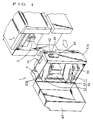
- a cut sheet feeder 1 shown in Fig. 1 is one preferred embodiment of the invention incorporated in a mimeograph printing machine 2.
- a sheet feed mechanism 3 furnished on the side of the printing machine 2 includes pick-up rollers for taking in cut sheets from the cut sheet feeder 1.
- the cut sheet feeder 1 positions to the sheet feed mechanism 3 either a cassette containing cut sheets or a sheet feed table carrying cut sheets stacked thereon.
- the cassette or the sheet feed table is moved up and down before coming into position to feed the printing machine 2 with necessary cut sheets.
- the cut sheet feeder 1 has a substantially box-like frame 6 comprising a right-and a left-hand side plate 4 and a bottom plate 5.
- the top portions of the side plates 4 and 4 are interconnected fixedly by use of bars 7.
- one side plate 4 has a motor 8 mounted on its outer surface near the bottom, the motor acting as a driving source of the cut sheet feeder 1.
- the motor 8 is coupled to the input shaft of a gear box 9 comprising reduction gears and clutches.
- the gear box 9 has two drive shafts A and B provided as its output shafts.
- the drive shafts A and B are in parallel and set apart from each other by a predetermined distance.
- the shafts A and B are furnished rotatably across the two side plates 4.
- a substantially box-like sheet feed unit 10 is furnished in a vertically movable manner inside the frame 6.
- the sheet feed unit 10 has a bottom plate 11 and a top cassette plate 12, the latter plate 12 serving as a first sheet feed table.
- the two plates 11 and 12 are coupled by use of a pair of side plates 13.
- the top cassette plate 12 has a sheet-containing cassette K placed thereon (see Fig. 7(b)).
- the cassette K is detached and the entire sheet feed unit 10 is set in an upward, appropriate position in a manner to be described later.
- the cassette plate 12 is kept from interfering with the pick-up rollers of the sheet feed mechanism 3. The interference is avoided by furnishing the cassette plate 12 with a cutout portion 14, as indicated in Figs. 1 and 2.
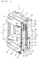
- Fig. 2 shows the frame 6 having vertically parallel guide grooves 15 and 16.
- a roller 70 attached rotatably to one edge of the bottom plate 11 moves freely up and down along one guide groove 15.
- Another roller 71 attached rotatably to one edge of the cassette plate 12 moves freely up and down along the other guide groove 16.
- a take-up pulley 17 is mounted on the tip of the drive shaft A protruding from the side plate 4.
- An intermediate pulley 18 is furnished on the side plate 4 and above the guide groove 15.
- One end of a wire 19 is attached to the circumference of the take-up pulley 17. The wire 19 is engaged around the intermediate pulley 18, and has its other end connected to the roller 70.
- the wire 19 pulls the roller 70 upward. This causes the sheet feed unit 10 to move up along the guide grooves 15 and 16 inside the frame 6.
- the wire 19 is unwound from the take-up pulley 17 to let the sheet feed unit 10 come down by its own weight. In this manner, the box-like sheet feed unit 10 is moved up and down inside the frame 6.
- an adjusting shaft 20 is provided above the bottom plate 11 of the sheet feed unit 10 and in parallel with the drive shafts A and B.
- the adjusting shaft 20 spans rotatably the side plates 13 of the sheet feed unit 10.
- One end of the adjusting shaft 20 protrudes from a groove 21 provided vertically along one side plate 4 of the frame 6.
- the protruding end of the adjusting shaft 20 has a pulley 22 mounted thereon.
- a thread portion 23 is provided in the middle of the adjusting shaft 20.
- a lower fence plate 24 Between the bottom plate 11 and the adjusting shaft 20 of the sheet feed unit 10 is a lower fence plate 24.
- the adjusting shaft 20 penetrates the edges 24a and 24b of the lower fence plate 24 with slide bushes 25 interposed between the shaft and the plate edges.
- the thread portion 23 of the adjusting shaft 20 engages with a thread receiver 27 fixed by fittings 26 to the top of the lower fence plate 24. In this setup, rotating the adjusting shaft 20 causes the lower fence plate 24 to move axially within the sheet feed unit 10.
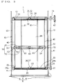
- the above-described mechanism for moving the lower fence plate 24 has its counterpart under the cassette plate 12 of the sheet feed unit 10, as shown in Fig. 3.
- a thread portion 29 of an adjusting shaft 28 engages with a thread receiver 32 fixed by fittings 31 to an upper fence plate 30.
- the upper adjusting shaft 28 penetrates a groove 35 provided on the side plate 4.
- Reference numeral 33 stands for slide bushes, and 34 for a pulley. The pulley is fixed to the adjusting shaft 28.
- the upper fence plate 30 and the lower fence plate 24 are coupled by use of guide shafts 40.
- a timing belt 41 is engaged around a pulley 34 of the upper fence plate 30 and around a pulley 22 of the lower fence plate 24.
- the adjusting shaft 28 of the upper fence plate 30 has a dial 42 for manual operation. The dial 42 when operated allows the adjusting shaft 28 to be rotated manually.
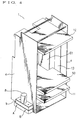
- the sheet feed unit 10 incorporates the sheet feed table 50 under the cassette plate 12.
- the sheet feed table 50 is vertically movable and serves as a second sheet feed table.
- the sheet feed table 50 comprises an upper tray 51 on which a large number of cut sheets are stacked, and a lower tray 52 that movably supports the upper tray 51.
- Guide members 54 are furnished on both sides of the upper tray 51.
- the guide shafts 40 penetrate the guide members 54.
- the upper tray 51 moves up and down along the guide shafts 40.
- rollers 55 are provided at both ends of support shafts 53 fixed to the lower tray 52.
- the side plate 4 of the frame 6 has two vertical guide grooves 56 with which the rollers 55 of the support shafts 53 are movably engaged.
- a take-up pulley 57 is attached to the end of the drive shaft B protruding from the side plate 4.
- Intermediate pulleys 58 are provided on the side plate 4 above the guide grooves 56.
- One end of each of two wires 59 is attached to the circumference of the take-up pulley 57. The two wires 59 are engaged respectively around the two different intermediate pulleys 58, and have their other ends attached to the two rollers 55.
- the side plate 4 opposite to the one shown in Fig. 2 has another identical mechanism for driving the sheet feed unit 10 and the sheet feed table 50 by use of the drive shafts A and B and of the wire and pulley arrangement. This mechanism is omitted in Fig. 4.
- a plurality of bearings 60 are provided on top of the lower tray 52. These bearings 60 carry the upper tray 51 in a freely movable manner.
- the upper tray 51 is movable vertically along the guide shafts 40 and horizontally along the support shafts 53.
- the dial 42 is manipulated to move the upper and lower fence plates 30 and 24 horizontally, the upper tray 51 of the sheet feed table 50 moves along the support shafts 53.
- two fences 61 are furnished in a horizontally movable manner between the upper and lower fence plates 30 and 24.
- sliders 73 are mounted slidingly on two parallel guide shafts 62 fixed to the lower fence plate 24.
- the lower portions of the fences 61 are fixed to the sliders 73 so that the fences 61 may be moved together with the sliders 73 along the guide shafts 62.
- the same mechanism is provided above the upper fence plate 30 and the fences 61. Fittings, also not shown, are provided to secure the fences 61 in position.
- the cover 63a on the one side has an approximately embossed opening portion 64 having a narrow part and a wide part.
- the narrow part corresponds in its opening to the diameter of the adjusting shaft 28 so that the shaft 28 may move vertically therein.
- the wide part corresponds in its opening to the diameter of the dial 42 so that the cover 63a may be detached from the cut sheet feeder 1 with the dial 42 left mounted on the adjusting shaft 28.
- the narrow and the wide part of the opening portion 64 are covered with lids 65 and 66 which constitute an outwardly embossed space for accommodating the dial 42.
- the lid 65 is formed integrally with the cover 63a.
- the lid 66 is formed by a transparent or translucent material and is attached swingingly to the lid 65 by use of a hinge 72.
- a mode changeover switch may be used to select a table feed mode for bulk printing.
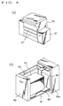
- the sheet feed unit 10 is raised as shown in Fig. 7(a) so that the cut sheets on the sheet feed table 50 will be positioned under the sheet feed mechanism 3 (for bulk sheet feed operation).
- the dial 42 is positioned in the narrow part of the opening portion 64 as depicted in Fig. 6(a). This leaves the dial 42 visible through the transparent lid 66. Opening the lid 66 allows the dial 42 to be operated manually.
- the mode changeover switch may also be used to select a cassette feed mode. In this mode, the sheet feed unit 10 is lowered as shown in Fig.
- a cover 67 installed swingingly, as shown in Fig. 1. Arrangements are made so that if the cover 67 is left open, the moving parts will not be driven or moved up or down. This ensures the operator's safety upon operation.
- the sheet feed unit 10 is lifted so that the cassette plate 12 will be positioned above the sheet feed mechanism 3, as shown in Fig. 7(a).
- the cutout portion 14 of the cassette plate 12 allows the entire sheet feed unit 10 including the plate 12 to go up without interference with the sheet feed mechanism 3.
- the sheet feed unit 10 is then positioned so that the pick-up rollers of the sheet feed mechanism 3 will come into contact, at a predetermined contact pressure, with the top of the cut sheets 68 stacked on the sheet feed table 50.
- the sheet feed mechanism 3 picks up the cut sheets 68 one by one and feeds them into the printing machine 2.
- the take-up pulley 57 takes up the wires 59 to compensate for the space vacated by the sheets having been fed, whereby the sheet feed table 50 is lifted correspondingly.
- the dial 42 In the table feed mode for bulk printing, the dial 42 is positioned upward where it may be operated manually. Manipulating the dial 42 fine-adjusts the crosswise positions of the upper and lower fence plates 30 and 24 as well as of the upper tray 51 on the sheet feed table 50 relative to the cut sheets 68.
- the cassette feed mode is first selected, and the sheet feed unit 10 is lowered as shown in Fig. 7(b) so that the cassette plate 12 will be positioned under the sheet feed mechanism 3. This time, too, the sheet feed mechanism 3 goes through the cutout portion 14 without interference with the cassette plate 12.
- the cassette K containing cut sheets 69 is mounted on the cassette plate 12.
- the sheet feed unit 10 is positioned so that the pick-up rollers of the sheet feed mechanism 3 will come into contact, at a predetermined contact pressure, with the top surface of the cut sheets 69 in the cassette K.
- the sheet feed mechanism 3 then starts feeding the sheets from the cassette.
- the dial 42 is hidden behind the lid 65 and will not be accessed even if the lid 66 is opened. That is, during the cassette-based feed operation carried out on demand halfway through bulk printing, the preset position of the sheet feed plate 50 is not disturbed inadvertently.
- the sheet feed mechanism 3 is a component of the printing machine 2.
- the sheet feed mechanism 3 may be furnished in the cut sheet feeder 1.
- the first sheet feed table is used as the plate for accommodating a cassette, and the second sheet feed table as the plate having a large number of cut sheets stacked thereon.
- the two sheet feed tables may both be used as the plates for accommodating cassettes.
- Another alternative is to furnish the first sheet feed table with positionally adjustable fences for aligning the edge positions of cut sheets so that cut sheets of a desired size may be placed directly (i.e., without using a cassette) on the first sheet feed table.
- the above embodiment comprises two plates, one for accommodating the cassette and the other for having cut sheets stacked directly thereon.
- all sheet feed tables including the first sheet feed table
- the lowest sheet feed table i.e., the second sheet feed table
- the cut sheet feeder accommodates a plurality of vertically movable sheet feed tables, and allows any one of the tables to be positioned selectively relative to a single sheet feed mechanism for sheet feed operation from the selected table to the mechanism.
- the cut sheets on one of the multiple tables may be picked up selectively by one sheet feed mechanism and fed into the image recording portion of the image forming apparatus.
- the single sheet feed mechanism feeds cut sheets selectively from one of the sheet feed tables into the image recording portion
- the sheet transport route remains unchanged from the sheet feed mechanism to the image recording portion.
- the sheet feed timing is thus kept constant, which eliminates the need for conventional devices or adjustments to keep constant the timing of feeding cut sheets to the image forming portion. This is particularly effective in improving the print quality of mimeograph printing machines wherein a slight deviation in sheet feed timing can result in the longitudinal misalignment of printed contents.
- the single sheet feed mechanism feeds cut sheets selectively from one of the sheet feed tables into the image recording portion offers another benefit. That is, the structure of the sheet transport route is simplified and this route is easier to maintain than conventional sheet transport routes. With the simply structured sheet transport route taking up less space, the cut sheet feeder as a whole may be manufactured smaller than ever before.
- the sheet feed unit vertically movable relative to the sheet feed mechanism has the first sheet feed table for accommodating a cassette, and the second sheet feed table for having cut sheets stacked thereon.
- the two fences on the second sheet feed table for aligning the edge positions of the cut sheets on the table are included within the sheet feed unit. This ensures a sufficient space in which to handle and accommodate the cassette.
- Cassettes are switched on the cassette accommodating plate depending on the desired size of cut sheets. The size of cut sheets may also be changed as desired on the sheet feed table for bulk printing.
- the edge positions of cut sheets in any of different sizes are aligned by the two fences on the second sheet feed table.
- the fences are contained inside the sheet feed unit and thus has no relevance to the cut sheets on the first sheet feed table. That is, the cut sheets of a given size on the first sheet feed table may be replaced by those of another size irrespective of the size of the cut sheets on the second sheet feed table.
Landscapes
- Engineering & Computer Science (AREA)
- Mechanical Engineering (AREA)
- Sheets, Magazines, And Separation Thereof (AREA)
Description
in a further preferred embodiment there is provided an operation part disposed on said sheet feed unit, the operation part being used to adjust the horizontal position of the second sheet feed table; a cover employed to cover the operation part when cut sheets are fed from the cassette plate and to expose the operation part when cut sheets are fed from the second sheet feed table.
Claims (8)
- A cut sheet feeder for use with an image forming apparatus, comprising:a sheet feed mechanism for picking up stacked cut sheets one at a time from a predetermined position and for feeding each sheet to an image recording portion; characterized by including:a sheet feed unit vertically movable relative to said sheet feed mechnism;a first sheet feed table (12) located in an upper part of said sheet feed unit and including a cutout portion for avoiding interference with said sheet feed mechanism when said first sheet feed table moves vertically in combination with said sheet feed unit; anda second sheet feed table (50) located in a lower part of said sheet feed unit and vertically movable relative to said sheet feed unit.
- A cut sheet feeder as claimed in claim 1 in which the first sheet feed table is a cassette plate which accommodates detachably a cassette containing cut sheets.
- A cut sheet feeder as claimed in claim 2 in which the second sheet feed table accommodates more cut sheets than said cassette.
- A cut sheet feeder according to claim 2 or 3, wherein the position of said second sheet feed table is horizontally adjustable.
- A cut sheet feeder according to claim 4, comprising: an operation part disposed on said sheet feed unit, said operation part being used to adjust the horizontal position of said second sheet feed table,
a cover employed to cover said operation part when cut sheets are fed from said cassette plate and to expose said operation part when cut sheets are fed from said second sheet feed table. - A cut sheet feeder as claimed in any preceding claim and including:a pair of fences furnished inside said sheet feed unit for aligning the edge positions of the cut sheets placed on said second sheet feed table.
- A cut sheet feeder as claimed in any preceding claim in which the first sheet feed table accommodates detachably and on top thereof a cassette containing cut sheets.
- A cut sheet feeder as claimed in any preceding claim in which the second sheet feed table accommodates cut sheets on top thereof, and includes:a pair of fences attached to said sheet feed unit in a positionally adjustable manner depending on the size of the cut sheets placed on said second sheet feed table, said fences aligning the edge positions of said cut sheets.
Applications Claiming Priority (4)
| Application Number | Priority Date | Filing Date | Title |
|---|---|---|---|
| JP05603793A JP3285648B2 (en) | 1993-03-16 | 1993-03-16 | Paper feeder of image forming device |
| JP05603093A JP3227253B2 (en) | 1993-03-16 | 1993-03-16 | Paper feeder of image forming device |
| JP56030/93 | 1993-03-16 | ||
| JP56037/93 | 1993-03-16 |
Publications (2)
| Publication Number | Publication Date |
|---|---|
| EP0615938A1 EP0615938A1 (en) | 1994-09-21 |
| EP0615938B1 true EP0615938B1 (en) | 1998-02-25 |
Family
ID=26396943
Family Applications (1)
| Application Number | Title | Priority Date | Filing Date |
|---|---|---|---|
| EP94301889A Expired - Lifetime EP0615938B1 (en) | 1993-03-16 | 1994-03-16 | Cut sheet feeder for image forming apparatus |
Country Status (3)
| Country | Link |
|---|---|
| US (1) | US5431383A (en) |
| EP (1) | EP0615938B1 (en) |
| DE (1) | DE69408584T2 (en) |
Cited By (1)
| Publication number | Priority date | Publication date | Assignee | Title |
|---|---|---|---|---|
| DE102006010920B4 (en) * | 2005-03-15 | 2009-04-02 | Pfu Ltd., Kahoku | magazine unit |
Families Citing this family (4)
| Publication number | Priority date | Publication date | Assignee | Title |
|---|---|---|---|---|
| JP3423469B2 (en) * | 1995-03-20 | 2003-07-07 | 東北リコー株式会社 | Paper feeder in image forming apparatus |
| US6806946B2 (en) * | 2002-12-17 | 2004-10-19 | Kabushiki Kaisha Toshiba | Feed paper apparatus |
| USD495278S1 (en) | 2004-02-02 | 2004-08-31 | Kent L. Kroeker | Shock absorber mounting |
| EP2933210A4 (en) | 2012-12-17 | 2017-08-09 | Canon Denshi Kabushiki Kaisha | Sheet material loading device, sheet material transporting device, image reading device, and image forming device |
Family Cites Families (6)
| Publication number | Priority date | Publication date | Assignee | Title |
|---|---|---|---|---|
| US4108427A (en) * | 1975-04-18 | 1978-08-22 | Canon Kabushiki Kaisha | Feeding device |
| US4332375A (en) * | 1979-05-10 | 1982-06-01 | Tokyo Shibaura Denki Kabushiki Kaisha | Copy sheet-feeding apparatus |
| JPS63165255A (en) * | 1986-12-25 | 1988-07-08 | Toshiba Corp | Paper feeding device |
| JPS6417722A (en) * | 1987-07-10 | 1989-01-20 | Ricoh Kk | Paper feed tray |
| JP2502316B2 (en) * | 1987-07-15 | 1996-05-29 | 株式会社リコー | Paper feeder |
| JP2635878B2 (en) * | 1992-02-06 | 1997-07-30 | 富士通株式会社 | Paper feeder |
-
1994
- 1994-03-15 US US08/213,008 patent/US5431383A/en not_active Expired - Lifetime
- 1994-03-16 DE DE69408584T patent/DE69408584T2/en not_active Expired - Fee Related
- 1994-03-16 EP EP94301889A patent/EP0615938B1/en not_active Expired - Lifetime
Cited By (1)
| Publication number | Priority date | Publication date | Assignee | Title |
|---|---|---|---|---|
| DE102006010920B4 (en) * | 2005-03-15 | 2009-04-02 | Pfu Ltd., Kahoku | magazine unit |
Also Published As
| Publication number | Publication date |
|---|---|
| EP0615938A1 (en) | 1994-09-21 |
| US5431383A (en) | 1995-07-11 |
| DE69408584D1 (en) | 1998-04-02 |
| DE69408584T2 (en) | 1998-06-18 |
Similar Documents
| Publication | Publication Date | Title |
|---|---|---|
| US5451039A (en) | Cut sheet feeder for image forming apparatus | |
| US5431383A (en) | Cut sheet feeder for image forming apparatus | |
| US5441246A (en) | Cut sheet feeder for image forming apparatus | |
| EP0555091B1 (en) | Paper feeders | |
| CA1161157A (en) | Facsimile method and apparatus with sheet feeding | |
| JP3285647B2 (en) | Paper feeder of image forming device | |
| GB2069982A (en) | Sheet feeding in facsimile apparatus | |
| JP3285648B2 (en) | Paper feeder of image forming device | |
| EP0623539B1 (en) | Cut sheet feeder for image forming apparatus | |
| US7184182B1 (en) | Image recording device | |
| JP3256018B2 (en) | Paper feeder of image forming device | |
| JP3227253B2 (en) | Paper feeder of image forming device | |
| JP3227255B2 (en) | Paper feeder of image forming device | |
| JP2931086B2 (en) | Back fence device for large-volume paper feeder | |
| JP3227254B2 (en) | Paper feeder of image forming device | |
| JPH06100184A (en) | Tray device for image forming device | |
| JPH082697A (en) | Longitudinal type paper feeding tray for image forming device | |
| JP2583876Y2 (en) | Document holding device | |
| JP2572824B2 (en) | Paper feeder | |
| JPH11106061A (en) | Paper sheet supplying device | |
| JPH06135577A (en) | Paper feeder of image former | |
| JPS6163834A (en) | Automatic original carrying device | |
| JPH06100180A (en) | Paper feeder for image forming device | |
| JPS63309481A (en) | Printer | |
| JPH01307357A (en) | Portable facsimile equipment |
Legal Events
| Date | Code | Title | Description |
|---|---|---|---|
| PUAI | Public reference made under article 153(3) epc to a published international application that has entered the european phase |
Free format text: ORIGINAL CODE: 0009012 |
|
| AK | Designated contracting states |
Kind code of ref document: A1 Designated state(s): DE FR GB |
|
| 17P | Request for examination filed |
Effective date: 19950304 |
|
| 17Q | First examination report despatched |
Effective date: 19961024 |
|
| GRAG | Despatch of communication of intention to grant |
Free format text: ORIGINAL CODE: EPIDOS AGRA |
|
| GRAG | Despatch of communication of intention to grant |
Free format text: ORIGINAL CODE: EPIDOS AGRA |
|
| GRAH | Despatch of communication of intention to grant a patent |
Free format text: ORIGINAL CODE: EPIDOS IGRA |
|
| GRAH | Despatch of communication of intention to grant a patent |
Free format text: ORIGINAL CODE: EPIDOS IGRA |
|
| GRAA | (expected) grant |
Free format text: ORIGINAL CODE: 0009210 |
|
| AK | Designated contracting states |
Kind code of ref document: B1 Designated state(s): DE FR GB |
|
| REF | Corresponds to: |
Ref document number: 69408584 Country of ref document: DE Date of ref document: 19980402 |
|
| ET | Fr: translation filed | ||
| PLBE | No opposition filed within time limit |
Free format text: ORIGINAL CODE: 0009261 |
|
| STAA | Information on the status of an ep patent application or granted ep patent |
Free format text: STATUS: NO OPPOSITION FILED WITHIN TIME LIMIT |
|
| 26N | No opposition filed | ||
| REG | Reference to a national code |
Ref country code: GB Ref legal event code: IF02 |
|
| PGFP | Annual fee paid to national office [announced via postgrant information from national office to epo] |
Ref country code: GB Payment date: 20080312 Year of fee payment: 15 |
|
| PGFP | Annual fee paid to national office [announced via postgrant information from national office to epo] |
Ref country code: FR Payment date: 20080311 Year of fee payment: 15 Ref country code: DE Payment date: 20080313 Year of fee payment: 15 |
|
| GBPC | Gb: european patent ceased through non-payment of renewal fee |
Effective date: 20090316 |
|
| REG | Reference to a national code |
Ref country code: FR Ref legal event code: ST Effective date: 20091130 |
|
| PG25 | Lapsed in a contracting state [announced via postgrant information from national office to epo] |
Ref country code: DE Free format text: LAPSE BECAUSE OF NON-PAYMENT OF DUE FEES Effective date: 20091001 |
|
| PG25 | Lapsed in a contracting state [announced via postgrant information from national office to epo] |
Ref country code: GB Free format text: LAPSE BECAUSE OF NON-PAYMENT OF DUE FEES Effective date: 20090316 Ref country code: FR Free format text: LAPSE BECAUSE OF NON-PAYMENT OF DUE FEES Effective date: 20091123 |