EP0615873A2 - Sealing arrangement - Google Patents
Sealing arrangement Download PDFInfo
- Publication number
- EP0615873A2 EP0615873A2 EP94103801A EP94103801A EP0615873A2 EP 0615873 A2 EP0615873 A2 EP 0615873A2 EP 94103801 A EP94103801 A EP 94103801A EP 94103801 A EP94103801 A EP 94103801A EP 0615873 A2 EP0615873 A2 EP 0615873A2
- Authority
- EP
- European Patent Office
- Prior art keywords
- edge
- sealing arrangement
- arrangement according
- glass plate
- shaped clamping
- Prior art date
- Legal status (The legal status is an assumption and is not a legal conclusion. Google has not performed a legal analysis and makes no representation as to the accuracy of the status listed.)
- Granted
Links
Images

Classifications
-
- B—PERFORMING OPERATIONS; TRANSPORTING
- B60—VEHICLES IN GENERAL
- B60J—WINDOWS, WINDSCREENS, NON-FIXED ROOFS, DOORS, OR SIMILAR DEVICES FOR VEHICLES; REMOVABLE EXTERNAL PROTECTIVE COVERINGS SPECIALLY ADAPTED FOR VEHICLES
- B60J10/00—Sealing arrangements
- B60J10/80—Sealing arrangements specially adapted for opening panels, e.g. doors
- B60J10/82—Sealing arrangements specially adapted for opening panels, e.g. doors for movable panels in roofs
Definitions
- the invention relates to a sealing arrangement for the gap between the rigid cover of a vehicle roof and the roof opening, in which the cover is glued from a glass plate with a base frame that is placed underneath and protrudes laterally, and between the glass plate circumference and roof opening, a gap seal with the protruding edge of the Basic frame is connected.
- Such a cover is known from DE-OS 36 39 894.
- This cover consists of a large number of individual parts that have to be put together during the final assembly.
- a circumferential T-shaped aluminum profile is placed between the glass plate and the actual seal, which must also be anchored against the protruding edge of the base frame. Overall, several operations and tools are required to create a finished lid.
- the present invention is based on the object of creating a sealing arrangement for such a cover, with which such a cover can be manufactured much more easily and in particular can be assembled from fewer individual parts.
- the gap seal has a U-shaped, armored clamping area made of an elastomer with a lip-shaped extension overlapping the edge of the glass plate and a sealing lip directed against the peripheral edge of the glass plate on one side of the clamping area and has on the other side extruded hollow chamber profile made of foam rubber and that the gap seal with its U-shaped clamping area is clamped onto a bent edge of the base frame.
- the gap seal which surrounds the glass plate and the base frame, can consist of a profile section A which extends over the front edge of the cover and has a sealing lip which projects laterally from the foam rubber profile to the roof opening, and a profile section B which extends over the other peripheral areas of the cover and one with a section bordering the foam rubber profile Legs of the U-shaped clamping area are perpendicular protruding sealing web, the two profile sections are permanently connected at their abutments to form a one-piece frame.
- the elastomer part of the gap seal expediently consists of EPDM with a Shore A hardness of approximately 70.
- the reinforcement of the U-shaped clamping area can consist of a vulcanized-in punched strip with incisions on the edge.
- the lip-shaped attachment has a stiffening in the form of an aluminum strip or punched strip, which extends above the U-shaped reinforcement.
- the U-shaped clamping area has on its leg on the glass plate side a horizontal extension directed towards the glass plate, into which an angled end of the reinforcement extends.
- the glass plate and base frame can be connected by means of an adhesive layer in such a way that the free end of the attachment is also embedded in the adhesive layer.
- sealing lip directed against the edge of the glass plate is designed as a triangular sealing hollow chamber with an indentation notch in the horizontal leg.
- the U-shaped clamping area can have a plurality of obliquely protruding clamping lips on its inside.
- the raised edge has a lateral bulge, which engages on one side in a corresponding recess of the one U-leg and the other U-leg is provided with a similar bulge, which in the through the bulge engaging rear recess of the edge.
- U-shaped clamping area is connected to the raised edge by means of an activatable adhesive.
- Such an activatable adhesive layer expediently has an internal, current-carrying copper strand for heating and activating the adhesive.
- the activatable adhesive is expediently applied to an inside of the U-shaped clamping area, in particular extruded and after being pushed on pressed and activated the clamping area on the bent edge.
- the cover which essentially consists of a glass plate 2 is enclosed on all sides by a gap seal 3 towards the roof opening 1.
- the gap seal 3 consists of two different profile sections, namely the profile section A on the front edge of the lid to be opened and the profile section B, which encloses the other areas of the lid 2.
- the profile section A to the profile section B has two joints 4 and 5, at which the profile sections A and B are glued together to form a closed frame.
- the glass plate 2 shows a longitudinal section through the edge region of the cover corresponding to the section line II-II according to FIG. 1. Thereafter, the glass plate 2 is first connected to a base frame 10, which is placed underneath and protrudes laterally in the edge region, by means of an interposed adhesive 11.
- the base frame 10 has on the outer circumference a raised edge 12 on which the gap seal 3 of the profile area A is pushed on, this gap seal 3 being constructed in detail as follows.
- the seal initially has a U-shaped clamping area 13 made of an elastomer, this elastomer e.g. can be made of EPDM with a Shore A hardness of about 70.
- This clamping area 13 is provided with a likewise U-shaped reinforcement 14 in the form of a vulcanized-in punched strip with incisions on the edge. From the top of this clamping area 13 protrudes toward the glass plate 2 towards a lip-shaped extension 15, which covers the edge of the glass plate 2 and is also provided with a stiffener 16 in the form of an aluminum strip or punched strip, this stiffening 16 extending beyond the reinforcement 14 of the Clamping area 13 extends.
- a sealing lip 17 protruding from the clamping area 13 to the peripheral edge of the glass plate 2 is provided, which essentially also effects a tolerance compensation to the glass plate 2. Furthermore, from the lower end of the leg of the clamping area 13 on the glass plate side, an extension 18 directed towards the glass plate 2 extends, into which an angled end 19 of the reinforcement 14 extends.
- a hollow chamber profile 20 made of foam rubber is extruded onto the clamping area 13, which is provided on its top and front with flocking 21 for sealing and better sliding with respect to the roof cutout 1.
- Fig. 3 shows a longitudinal section through the profile areas B on the other sides of the glass plate 2.
- the seal 3 differs from the profile area A shown in Fig. 2 only in that the outer leg of the clamping area 13 has a vertically projecting sealing web 25 and one likewise downwardly projecting sealing lip 23 from the foam rubber area 20, which corresponds to the sealing lip 22 according to FIG. 2 projecting towards the roof cutout 1.
- the two profile sections A and B are now glued together at their joints 4 and 5 and pushed onto the upstanding edge 12 of the base frame 10 as a closed frame.
- the adhesive 11 is heated so that the protruding projections 18 of the clamping area 13 are embedded in the adhesive 11 and are thus additionally anchored.
- the U-shaped clamping area 13 has a plurality of obliquely protruding clamping lips 30 on its inside, which are directed against the withdrawal direction from the edge 12 and thus prevent the profile from being pulled out.
- FIGS. 4 to 6 Further clamping options are shown in FIGS. 4 to 6. 4, a U-shaped bracket 31 is placed on the bent edge 12, which has outwardly bent ends 32, which in corresponding Recesses 33 protrude on the inside of the U-shaped clamping area 13. The clips 31 can be firmly connected to the edge 12, so that a firm locking of the gap seal is possible.
- a somewhat differently designed clip 35 is pushed onto the bent edge 12.
- the clamp 35 likewise has outwardly projecting ends 36 which protrude into corresponding recesses 37 in the U-shaped clamping region 13.
- the raised edge still has indentations 38, into which correspondingly retracted areas 39 of the clamp 35 snap. This also ensures secure anchoring.
- FIG. 6 Another possibility is shown in FIG. 6. Thereafter, the raised edge 12 has a lateral bulge 40, the bulged side engaging in a corresponding recess 41 on one U-leg of the clamping area 13, while the other U-leg has a similar bulge 42, which in the corresponding recess of the Bulge 40 engages. This also ensures a secure locking of the gap seal.
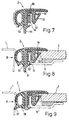
- FIGS. 7 to 9. 7 shows a cross section through this gap seal for the profile area B.
- a U-shaped clamping area 50 with a downwardly projecting projection 51 is also provided on one leg of the clamping area.
- the other leg 52 has a triangular sealing hollow chamber 53, in the horizontal leg of which an indentation notch 54 is provided.
- this triangular sealing hollow chamber 53 seals against the circumferential edge of the glass plate 2 and here offers a tolerance compensation for the gap seal and the glass pane 2 through the indentation notch 54.
- an activatable adhesive 55 is applied or extruded onto the inside of the outer leg of the U-shaped clamping area 50.
- Such an activatable adhesive 55 consists, for example, of a PU granulate, in the interior of which, for example, a copper wire 56 connected to a power source is embedded.
- a copper wire 56 connected to a power source is embedded.
- the activatable adhesive 55 is initially somewhat compressed after the gap seal 3 has been pushed onto the bent edge 12 of the frame 10 and, after its activation, forms a firm connection between the U-shaped clamping area 50 and the bent edge 12 of the frame 10.
- Fig. 9 shows a longitudinal section through this gap seal 3 in the region of the profile section A at the front edge of the roof opening, the profile here only differing from the profile region B in that the vertical extension 51 according to FIG. 8 is absent and the foam rubber region 56 is inclined downwardly projecting sealing lip 57 is provided for roof cutout 1.
Abstract
Description
Die Erfindung bezieht sich auf eine Dichtungsanordnung für den Spalt zwischen dem starren Deckel eines Fahrzeugdaches und der Dachöffnung, bei der der Deckel aus einer Glasplatte mit einem im Randbereich untergelegten und seitlich überstehenden Grundrahmen verklebt ist und zwischen Glasplattenumfang und Dachöffnung eine Spaltdichtung mit dem überstehenden Rand des Grundrahmens verbunden ist.The invention relates to a sealing arrangement for the gap between the rigid cover of a vehicle roof and the roof opening, in which the cover is glued from a glass plate with a base frame that is placed underneath and protrudes laterally, and between the glass plate circumference and roof opening, a gap seal with the protruding edge of the Basic frame is connected.
Ein derartiger Deckel ist aus der DE-OS 36 39 894 bekannt. Dabei besteht dieser Deckel aus einer Vielzahl von Einzelteilen, die bei der Endmontage aufwendig zusammengefügt werden müssen. Hierbei ist zwischen der Glasplatte und der eigentlichen Dichtung noch ein umlaufendes T-förmiges Aluprofil aufgelegt, das zusätzlich gegen den überstehenden Rand des Grundrahmens verankert werden muß. Insgesamt sind mehrere Arbeitsgänge und Hilfsmittel erforderlich, um einen fertigen Deckel zu schaffen.Such a cover is known from DE-OS 36 39 894. This cover consists of a large number of individual parts that have to be put together during the final assembly. Here, a circumferential T-shaped aluminum profile is placed between the glass plate and the actual seal, which must also be anchored against the protruding edge of the base frame. Overall, several operations and tools are required to create a finished lid.
Der vorliegenden Erfindung liegt demgegenüber die Aufgabe zugrunde, eine Dichtungsanordnung für einen solchen Deckel zu schaffen, mit der ein solcher Deckel sehr viel einfacher hergestellt und insbesondere aus weniger Einzelteilen montiert werden kann.In contrast, the present invention is based on the object of creating a sealing arrangement for such a cover, with which such a cover can be manufactured much more easily and in particular can be assembled from fewer individual parts.
Zur Lösung dieser Aufgabe ist erfindungsgemäß vorgesehen, daß die Spaltdichtung einen U-förmigen, mit einer Armierung versehenen Klemmbereich aus einem Elastomer mit einem den Rand der Glasplatte übergreifenden lippenförmigen Ansatz sowie einer gegen den umlaufenden Rand der Glasplatte gerichteten Dichtlippe auf der einen Seite des Klemmbereiches sowie einem auf der anderen Seite anextrudierten Hohlkammerprofil aus Moosgummi aufweist und daß die Spaltdichtung mit ihrem U-förmigen Klemmbereich auf einen hochgebogenen Rand des Grundrahmens aufgeklemmt ist.To achieve this object, it is provided according to the invention that the gap seal has a U-shaped, armored clamping area made of an elastomer with a lip-shaped extension overlapping the edge of the glass plate and a sealing lip directed against the peripheral edge of the glass plate on one side of the clamping area and has on the other side extruded hollow chamber profile made of foam rubber and that the gap seal with its U-shaped clamping area is clamped onto a bent edge of the base frame.
Damit ist es möglich, die gesamte Spaltdichtung als einstückiges Bauteil und als geschlossenen Rahmen herzustellen, der dann nur noch von oben auf den Rand des Grundrahmens aufgeschoben werden muß.This makes it possible to produce the entire gap seal as a one-piece component and as a closed frame, which then only has to be pushed onto the edge of the base frame from above.
Dabei kann die die Glasplatte und den Grundrahmen geschlossen umziehende Spaltdichtung aus einem sich über die Vorderkante des Deckels erstreckenden Profilabschnitt A mit einer seitlich vom Moosgummiprofil zur Dachöffnung abragenden Dichtlippe und einen sich über die übrigen Umfangsbereiche des Deckels erstreckenden Profilabschnitt B mit einem vom an das Moosgummiprofil angrenzenden Schenkel des U-förmigen Klemmbereiches senkrecht abragenden Dichtsteg bestehen, wobei die beiden Profilabschnitte an ihren Stoßstellen zu einem einstückigen Rahmen dauerhaft verbunden sind.The gap seal, which surrounds the glass plate and the base frame, can consist of a profile section A which extends over the front edge of the cover and has a sealing lip which projects laterally from the foam rubber profile to the roof opening, and a profile section B which extends over the other peripheral areas of the cover and one with a section bordering the foam rubber profile Legs of the U-shaped clamping area are perpendicular protruding sealing web, the two profile sections are permanently connected at their abutments to form a one-piece frame.
Zweckmäßigerweise besteht der Elastomerteil der Spaltdichtung aus EPDM mit einer Shore-A-Härte von etwa 70.The elastomer part of the gap seal expediently consists of EPDM with a Shore A hardness of approximately 70.
Die Armierung des U-förmigen Klemmbereiches kann aus einem einvulkanisierten Stanzband mit randseitigen Einschnitten bestehen.The reinforcement of the U-shaped clamping area can consist of a vulcanized-in punched strip with incisions on the edge.
Darüberhinaus ist es zweckmäßig, wenn der lippenförmige Ansatz eine sich bis oberhalb der U-förmigen Armierung erstreckende Versteifung in Form eines Aluminiumbandes oder Stanzbandes aufweist. Zur weiteren Halterung ist es ferner zweckmäßig, wenn der U-förmige Klemmbereich an seinem glasplattenseitigen Schenkel einen horizontalen, zur Glasplatte hin gerichteten Ansatz aufweist, in den sich ein abgewinkeltes Ende der Armierung erstreckt.In addition, it is expedient if the lip-shaped attachment has a stiffening in the form of an aluminum strip or punched strip, which extends above the U-shaped reinforcement. For further mounting, it is furthermore expedient if the U-shaped clamping area has on its leg on the glass plate side a horizontal extension directed towards the glass plate, into which an angled end of the reinforcement extends.
Dabei können Glasplatte und Grundrahmen mittels einer Kleberschicht derart verbunden sein, daß auch das freie Ende des Ansatzes mit in die Kleberschicht eingebettet ist.The glass plate and base frame can be connected by means of an adhesive layer in such a way that the free end of the attachment is also embedded in the adhesive layer.
Ferner ist es zweckmäßig, wenn die gegen den Rand der Glasplatte gerichtete Dichtlippe als dreieckförmige Dichthohlkammer mit einer Eindrückkerbe im horizontalen Schenkel ausgebildet ist.It is also expedient if the sealing lip directed against the edge of the glass plate is designed as a triangular sealing hollow chamber with an indentation notch in the horizontal leg.
Zur Befestigung des U-förmigen Klemmbereiches auf dem hochgebogenen Rand gibt es verschiedene Möglichkeiten.There are various options for fastening the U-shaped clamping area on the raised edge.
So kann der U-förmige Klemmbereich auf seiner Innenseite mehrere, schräg abragende Klemmlippen aufweisen.Thus, the U-shaped clamping area can have a plurality of obliquely protruding clamping lips on its inside.
Des weiteren ist es möglich, zur Arretierung dieses U-förmigen Klemmbereiches auf den hochgebogenen Rand des Grundrahmens U-förmige Klammern mit nach außen abgebogenen Schenkelenden vorzusehen, welche Schenkelenden in entsprechende Ausnehmungen des U-förmigen Klemmbereiches ragen.Furthermore, it is possible, in order to lock this U-shaped clamping area onto the raised edge of the base frame, to provide U-shaped clips with leg ends bent outwards, which leg ends protrude into corresponding recesses in the U-shaped clamping area.
Eine weitere Möglichkeit besteht darin, daß der hochgebogene Rand eine seitliche Auswölbung aufweist, der auf der einen Seite in eine entsprechende Ausnehmung des einen U-Schenkels eingreift und wobei der andere U-Schenkel mit einer gleichartigen Auswölbung versehen ist, die in die durch die Auswölbung entstehende rückseitige Ausnehmung des Randes eingreift.Another possibility is that the raised edge has a lateral bulge, which engages on one side in a corresponding recess of the one U-leg and the other U-leg is provided with a similar bulge, which in the through the bulge engaging rear recess of the edge.
Eine weitere sehr vorteilhafte Befestigungsmethode besteht darin, daß der U-förmige Klemmbereich mittels eines aktivierbaren Klebers mit dem hochgebogenen Rand verbunden ist.Another very advantageous fastening method is that the U-shaped clamping area is connected to the raised edge by means of an activatable adhesive.
Eine solche aktivierbare Kleberschicht weist zweckmäßigerweise eine innenliegende, stromdurchflossene Kupferlitze zur Erwärmung und Aktivierung des Klebers auf.Such an activatable adhesive layer expediently has an internal, current-carrying copper strand for heating and activating the adhesive.
Dabei ist die aktvierbare Klebermasse zweckmäßigerweise auf einer Innenseite des U-förmigen Klemmbereiches aufgebracht, insbesondere aufextrudiert und nach Aufschieben des Klemmbereiches auf den hochgebogenen Rand angepreßt und aktiviert.The activatable adhesive is expediently applied to an inside of the U-shaped clamping area, in particular extruded and after being pushed on pressed and activated the clamping area on the bent edge.
Anhand einer schematischen Zeichnung sind Aufbau und Funktionsweise von Ausführungsbeispielen nach der Erfindung näher erläutert. Dabei zeigen:
- Fig. 1
- eine Aufsicht auf den Deckel innerhalb der Dachöffnung,
- Fig. 2
- einen Längsschnitt durch den Randbereich des Deckels an der Vorderkante mit einer aufgesetzten Dichtung entsprechend der Schnittlinie II-II nach Fig. 1,
- Fig. 3
- eine gleichartige Dichtung wie Fig. 2 für die übrigen, umlaufenden Bereiche des Deckels entsprechend der Schnittlinie III-III nach Fig. 1,
- Fig. 4
- die Ausbildung einer Klemmanordnung zur Halterung der Spaltdichtung,
- Fig. 5
- eine weitere Ausgestaltung einer solchen Klemmanordnung,
- Fig. 6
- eine dritte Variante für eine derartige Klemmanordnung,
- Fig. 7
- einen Querschnitt durch eine fertige Spaltdichtung mit aktivierbarem Kleber,
- Fig. 8
- einen Längsschnitt durch den Randbereich des Deckels an der Vorderkante mit einer Dichtung entsprechend Fig. 7 und
- Fig. 9
- eine solche Spaltdichtung für die übrigen, umlaufenden Bereiche des Deckels.
- Fig. 1
- a view of the lid inside the roof opening,
- Fig. 2
- 2 shows a longitudinal section through the edge region of the cover at the front edge with an attached seal corresponding to section line II-II according to FIG. 1,
- Fig. 3
- 2 shows a seal similar to FIG. 2 for the remaining circumferential areas of the cover according to section line III-III according to FIG. 1,
- Fig. 4
- the formation of a clamping arrangement for holding the gap seal,
- Fig. 5
- a further embodiment of such a clamping arrangement,
- Fig. 6
- a third variant for such a clamping arrangement,
- Fig. 7
- a cross section through a finished gap seal with activatable adhesive,
- Fig. 8
- a longitudinal section through the edge region of the lid on the front edge with a seal corresponding to FIGS. 7 and
- Fig. 9
- such a gap seal for the other peripheral areas of the lid.
Nach der in Fig. 1 dargestellten Aufsicht auf ein Fahrzeugdach mit einer rechteckigen Dachöffnung 1 ist der im wesentlichen aus einer Glasplatte 2 bestehende Deckel allseitig von einer Spaltdichtung 3 zur Dachöffnung 1 hin umschlossen. Die Spaltdichtung 3 besteht dabei aus zwei unterschiedlichen Profilabschnitten, nämlich dem Profilabschnitt A an der zu öffnenden Vorderkante des Deckels und dem Profilabschnitt B, der die übrigen Bereiche des Deckels 2 umschließt. Dabei weist der Profilabschnitt A zum Profilabschnitt B zwei Stoßstellen 4 und 5 auf, an denen die Profilabschnitte A und B miteinander zu einem geschlossenen Rahmen verklebt sind.According to the plan view of a vehicle roof with a rectangular roof opening 1 shown in FIG. 1, the cover, which essentially consists of a
In Fig. 2 ist ein Längsschnitt durch den Randbereich des Deckels entsprechend der Schnittlinie II-II nach Fig. 1 gezeigt. Danach ist zunächst die Glasplatte 2 mit einem untergelegten und im Randbereich seitlich überstehenden Grundrahmen 10 über einen zwischengefügten Kleber 11 zu einer Baueinheit verbunden.2 shows a longitudinal section through the edge region of the cover corresponding to the section line II-II according to FIG. 1. Thereafter, the
Der Grundrahmen 10 weist am Außenumfang einen hochgebogenen Rand 12 auf, auf den die Spaltdichtung 3 des Profilbereiches A aufgeschoben ist, wobei diese Spaltdichtung 3 im einzelnen wie folgt aufgebaut ist.The
Die Dichtung weist zunächst einen U-förmigen Klemmbereich 13 aus einem Elastomer auf, wobei dieses Elastomer z.B. aus EPDM mit einer Shore-A-Härte von etwa 70 bestehen kann. Dieser Klemmbereich 13 ist mit einer ebenfalls U-förmigen Armierung 14 in Form eines einvulkanisierten Stanzbandes mit randseitigen Einschnitten versehen. Von der Oberseite dieses Klemmbereiches 13 ragt zur Glasplatte 2 hin ein lippenförmiger Ansatz 15 ab, der den Rand der Glasplatte 2 überdeckt und ebenfalls mit einer Versteifung 16 in Form eines Aluminiumbandes oder Stanzbandes versehen ist, wobei sich diese Versteifung 16 bis über die Armierung 14 des Klemmbereiches 13 erstreckt. Ferner ist eine vom Klemmbereich 13 zum umlaufenden Rand der Glasplatte 2 abragende Dichtlippe 17 vorgesehen, die im wesentlichen auch einen Toleranzausgleich zur Glasplatte 2 bewirkt. Ferner geht vom unteren Ende des glasplattenseitigen Schenkels des Klemmbereiches 13 ein zur Glasplatte 2 hin gerichteter Ansatz 18 aus, in den sich ein abgewinkeltes Ende 19 der Armierung 14 erstreckt.The seal initially has a
Auf der gegenüberliegenden Seite des Klemmbereiches 13 zum Dachausschnitt 1 hin ist an den Klemmbereich 13 ein Hohlkammerprofil 20 aus Moosgummi anextrudiert, das auf seiner Ober- und Vorderseite mit einer Beflockung 21 zur Abdichtung und besseren Gleitung gegenüber dem Dachausschnitt 1 versehen ist.On the opposite side of the clamping
Fig. 3 zeigt einen Längsschnitt durch die Profilbereiche B auf den übrigen Seiten der Glasplatte 2. Hierbei unterscheidet sich die Dichtung 3 von dem in Fig. 2 gezeigten Profilbereich A nur dadurch, daß der außenliegende Schenkel des Klemmbereiches 13 einen senkrecht abragenden Dichtsteg 25 sowie einer ebenfalls nach unten ragenden Dichtlippe 23 vom Moosgummibereich 20, die der nach vorn zum Dachausschnitt 1 ragenden Dichtlippe 22 nach Fig. 2 entspricht.Fig. 3 shows a longitudinal section through the profile areas B on the other sides of the
Zur Montage werden nun die beiden Profilabschnitte A und B an ihren Stoßstellen 4 und 5 miteinander verklebt und als somit geschlosssener Rahmen auf den hochstehenden Rand 12 des Grundrahmens 10 aufgeschoben. Zur besseren Verankerung wird der Kleber 11 erwärmt, so daß die abragenden Ansätze 18 des Klemmbereiches 13 mit in den Kleber 11 eingebettet und damit zusätzlich verankert sind.For assembly, the two profile sections A and B are now glued together at their
Zur besseren Verankerung der aufgeklemmten Spaltdichtung 3 können verschiedene Möglichkeiten vorgesehen sein. Nach Fig. 3 weist der U-förmige Klemmbereich 13 auf seiner Innenseite mehrere schräg abragende Klemmlippen 30 auf, die entgegen der Abzugsrichtung vom Rand 12 gerichtet sind und damit ein Herausziehen des Profils verhindern.Various possibilities can be provided for better anchoring of the clamped gap seal 3. According to FIG. 3, the
Weitere Klemmöglichkeiten sind in den Fig. 4 bis 6 gezeigt. Nach Fig. 4 ist auf den hochgebogenen Rand 12 eine U-förmige Klammer 31 aufgesetzt, die nach außen abgeknickte Enden 32 aufweist, die in entsprechende Ausnehmungen 33 auf der Innenseite des U-förmigen Klemmbereiches 13 hineinragen. Die Klammern 31 können dabei mit dem Rand 12 fest verbunden sind, so daß damit eine feste Arretierung der Spaltdichtung möglich ist.Further clamping options are shown in FIGS. 4 to 6. 4, a
Nach Fig. 5 ist eine etwas anders gestaltete Klammer 35 auf den hochgebogenen Rand 12 aufgeschoben. Hierbei weist die Klammer 35 ebenfalls nach außen ragende Enden 36 auf, die in entsprechende Ausnehmungen 37 des U-förmigen Klemmbereiches 13 hineinragen. Zusätzlich weist der hochgebogene Rand aber noch Einziehungen 38 auf, in den entsprechend eingezogene Bereiche 39 der Klammer 35 einrasten. Auch hiermit ist eine sichere Verankerung gewährleistet.According to FIG. 5, a somewhat differently designed
Eine weitere Möglichkeit ist in Fig. 6 dargestellt. Danach weist der hochgebogene Rand 12 eine seitliche Auswölbung 40 auf, wobei die ausgewölbte Seite in eine entsprechende Ausnehmung 41 auf dem einen U-Schenkel des Klemmbereiches 13 eingreift, während der andere U-Schenkel eine gleichartige Auswölbung 42 besitzt, die in die entsprechende Vertiefung der Auswölbung 40 eingreift. Auch hiermit ist eine sichere Arretierung der Spaltdichtung gewährleistet.Another possibility is shown in FIG. 6. Thereafter, the raised
Eine etwas anders gestaltete und befestigte Spaltdichtung 3 ist in den Fig. 7 bis 9 dargestellt. Fig. 7 zeigt einen Querschnitt durch diese Spaltdichtung für den Profilbereich B. Danach ist auch hier ein U-förmiger Klemmbereich 50 mit einem nach unten ragenden Ansatz 51 an einem Schenkel des Klemmbereiches vorgesehen. Der andere Schenkel 52 weist dagegen eine dreieckförmige Dichthohlkammer 53 auf, in dessem horizontalen Schenkel eine Eindrückkerbe 54 vorgesehen ist.A slightly differently designed and attached gap seal 3 is shown in FIGS. 7 to 9. 7 shows a cross section through this gap seal for the profile area B. According to this, a
Wie man aus dem entsprechenden Längsschnitt entsprechend Fig. 8 für den Einbauzustand ersieht, dichtet diese dreieckförmige Dichthohlkammer 53 gegen die umlaufende Kante der Glasplatte 2 ab und bietet hier durch die Eindrückkerbe 54 einen Toleranzausgleich für Spaltdichtung und Glasscheibe 2.As can be seen from the corresponding longitudinal section corresponding to FIG. 8 for the installed state, this triangular sealing
Zusätzlich ist auf der Innenseite des außenliegenden Schenkels des U-förmigen Klemmbereiches 50 ein aktivierbarer Kleber 55 aufgebracht bzw. aufextrudiert. Ein solcher aktivierbarer Kleber 55 besteht beispielsweise aus einem PU-Granulat, in dessem Inneren beispielsweise eine an eine Stromquelle angeschlossene Kupferlitze 56 eingebettet ist. Bei einem Stromdurchfluß und damit Erwärmung der Kupferlitze 54 wird auch der umgebende Kleber heiß und damit aktiviert, so daß dann nach Abschalten der Stromquelle und Erkalten der Klebermasse eine feste Verbindung zum anliegenden Bauteil gewährleistet ist.In addition, an
Wie man dazu aus Fig. 8 ersieht, ist der aktivierbare Kleber 55 nach Aufschieben der Spaltdichtung 3 auf den hochgebogenen Rand 12 des Rahmens 10 zunächst etwas zusammengepreßt und bildet nach seiner Aktivierung eine feste Verbindung zwischen dem U-förmigen Klemmbereich 50 und dem hochgebogenen Rand 12 des Rahmens 10.As can be seen from FIG. 8, the
Fig. 9 zeigt einen Längsschnitt durch diese Spaltdichtung 3 im Bereich des Profilabschnittes A an der Vorderkante der Dachöffnung, wobei sich hier das Profil gegenüber dem Profilbereich B nur dadurch unterscheidet, daß der senkrechte Ansatz 51 nach Fig. 8 fehlt und vom Moosgummibereich 56 eine schräg nach unten abragende Dichtlippe 57 zum Dachauschnitt 1 vorgesehen ist.Fig. 9 shows a longitudinal section through this gap seal 3 in the region of the profile section A at the front edge of the roof opening, the profile here only differing from the profile region B in that the
Insgesamt ergibt sich somit eine Spaltdichtung für den Spalt zwischen Glasdeckel und umlaufendem Dachausschnitt, die als fertiger, rechteckiger Profilrahmen vorgefertigt und dann einstückig auf den hochgebogenen Rand dem der Glasplatte untergelegten Grundrahmen aufgesteckt und arretiert werden kann.Overall, this results in a gap seal for the gap between the glass cover and the circumferential roof cutout, which is prefabricated as a finished, rectangular profile frame and can then be attached and locked in one piece on the raised edge of the base frame under the glass plate.
Claims (14)
Applications Claiming Priority (2)
| Application Number | Priority Date | Filing Date | Title |
|---|---|---|---|
| DE4308218 | 1993-03-15 | ||
| DE4308218A DE4308218C2 (en) | 1993-03-15 | 1993-03-15 | Sealing arrangement |
Publications (3)
| Publication Number | Publication Date |
|---|---|
| EP0615873A2 true EP0615873A2 (en) | 1994-09-21 |
| EP0615873A3 EP0615873A3 (en) | 1995-02-01 |
| EP0615873B1 EP0615873B1 (en) | 1999-10-13 |
Family
ID=6482857
Family Applications (1)
| Application Number | Title | Priority Date | Filing Date |
|---|---|---|---|
| EP94103801A Expired - Lifetime EP0615873B1 (en) | 1993-03-15 | 1994-03-11 | Sealing arrangement |
Country Status (5)
| Country | Link |
|---|---|
| US (1) | US5538317A (en) |
| EP (1) | EP0615873B1 (en) |
| JP (1) | JP2757296B2 (en) |
| AT (1) | ATE185523T1 (en) |
| DE (2) | DE4308218C2 (en) |
Families Citing this family (33)
| Publication number | Priority date | Publication date | Assignee | Title |
|---|---|---|---|---|
| ES2145478T3 (en) * | 1995-08-25 | 2000-07-01 | Draftex Ind Ltd | SHUTTER AND GUIDE BANDS. |
| JPH09123769A (en) * | 1995-10-30 | 1997-05-13 | Toyota Autom Loom Works Ltd | Slide window made of resin |
| DE19754402B4 (en) * | 1997-12-09 | 2007-03-15 | Webasto Ag | Two-piece seal on a lid of an openable vehicle roof |
| DE19754403C1 (en) * | 1997-12-09 | 1999-01-07 | Webasto Systemkomponenten Gmbh | Openable transparent vehicle roof panel |
| JP2000296718A (en) * | 1999-04-14 | 2000-10-24 | Toyota Autom Loom Works Ltd | Weather strip installing structure of sliding roof |
| DE19921233C2 (en) * | 1999-05-07 | 2001-06-28 | Metzeler Automotive Profiles | Sealing arrangement for sealing a closing part |
| DE10005642B4 (en) * | 2000-02-09 | 2004-04-29 | Metzeler Automotive Profile Systems Gmbh | Edge gap seal |
| JP2001301470A (en) * | 2000-04-21 | 2001-10-31 | Toyoda Gosei Co Ltd | Sealing structure for outer periphery of glass lid for sunroof |
| JP4113999B2 (en) * | 2000-04-28 | 2008-07-09 | 株式会社豊田自動織機 | Translucent panel mounting structure and translucent panel assembly method in vehicle |
| JP4284828B2 (en) * | 2000-04-28 | 2009-06-24 | 株式会社豊田自動織機 | Translucent panel mounting structure for vehicle |
| DE10035912C2 (en) * | 2000-07-21 | 2003-05-15 | Webasto Vehicle Sys Int Gmbh | Plastic covers for vehicles |
| DE10042439B4 (en) * | 2000-08-30 | 2004-07-08 | Bayerische Motoren Werke Ag | Carrier flange of a motor vehicle for an attachable seal |
| DE10043136B4 (en) * | 2000-08-31 | 2013-08-01 | Webasto Ag | Sealing profile, in particular for a sunroof gasket |
| DE10122637B4 (en) * | 2001-03-16 | 2005-07-21 | Wagon Automotive Gmbh | Sealing arrangement for a motor vehicle door and / or a motor vehicle window |
| JP3704645B2 (en) * | 2002-03-20 | 2005-10-12 | 西川ゴム工業株式会社 | Weather strip for sunroof |
| US6814813B2 (en) * | 2002-04-24 | 2004-11-09 | Micron Technology, Inc. | Chemical vapor deposition apparatus |
| DE102004003566B4 (en) * | 2003-01-31 | 2005-09-15 | Toyoda Gosei Co., Ltd. | Fixing structure for a weather strip for a motor vehicle |
| US20050161886A1 (en) * | 2004-01-28 | 2005-07-28 | Berry David H. | Heat-activated expandable seal and method for producing same |
| GB2432870A (en) * | 2005-11-18 | 2007-06-06 | Gdx North America Inc | Sealing assemblies and methods of making them |
| US8516749B2 (en) * | 2008-02-20 | 2013-08-27 | Pilkington Group Limited | Encapsulated window assembly with integral seal and method of installing game |
| US9580954B2 (en) | 2009-10-05 | 2017-02-28 | R Value, Inc. | Press fit storm window system |
| US9255438B2 (en) | 2009-10-05 | 2016-02-09 | R Value, Inc. | Press fit storm window system |
| US10202796B2 (en) | 2009-10-05 | 2019-02-12 | R Value, Inc. | Press fit storm window system |
| CA2806334A1 (en) | 2010-07-28 | 2012-02-02 | Press-Seal Gasket Corporation | Trailer door seal |
| DE202011000804U1 (en) * | 2011-04-06 | 2012-07-09 | Richard Fritz Gmbh + Co. Kg | Disk unit for windows on motor vehicles |
| PL2755866T3 (en) | 2011-09-15 | 2018-06-29 | Henniges Automotive Sealing Systems North America, Inc. | Weatherstrip assembly having a removable retaining member |
| DE102012023043A1 (en) * | 2012-05-10 | 2013-11-14 | GM Global Technology Operations LLC (n. d. Gesetzen des Staates Delaware) | Sealing strip for a motor vehicle, in particular window sill sealing strip |
| DE102012106340B4 (en) * | 2012-07-13 | 2022-07-14 | Bayerische Motoren Werke Aktiengesellschaft | Sealing strip for bonding to a vehicle body |
| US9032668B2 (en) | 2012-09-07 | 2015-05-19 | Press-Seal Gasket Corporation | Seal with primary and secondary sealing lobes for use in roll-up door applications |
| US8959859B2 (en) * | 2012-09-17 | 2015-02-24 | Steelcase Inc. | Floor-to-ceiling partition wall assembly |
| US9151107B2 (en) | 2013-09-24 | 2015-10-06 | Press-Seal Gasket Corporation | Trailer door seal |
| EP3113966B1 (en) * | 2014-02-07 | 2019-04-10 | Henniges Automotive Sealing Systems North America, Inc. | Method of manufacturing a vehicle sealing assembly |
| DE102017207344A1 (en) * | 2017-05-02 | 2018-11-08 | Skf Marine Gmbh | Covering device and thruster |
Citations (3)
| Publication number | Priority date | Publication date | Assignee | Title |
|---|---|---|---|---|
| DE3639894A1 (en) * | 1986-11-21 | 1988-06-01 | Rockwell Golde Gmbh | Rigid cover for a vehicle roof |
| US4757643A (en) * | 1985-11-26 | 1988-07-19 | Vermeulen-Hollandia Octrooien Ii B.V. | Elastic seal for a displaceable panel of an open roof construction for a vehicle |
| US5170587A (en) * | 1990-09-03 | 1992-12-15 | Toyoda Gosei Co., Ltd. | Weatherstrip for automotive vehicle |
Family Cites Families (16)
| Publication number | Priority date | Publication date | Assignee | Title |
|---|---|---|---|---|
| US2772915A (en) * | 1954-06-01 | 1956-12-04 | Motor Products Corp | Window assembly for vehicle bodies |
| US3171886A (en) * | 1960-12-12 | 1965-03-02 | Hall C M Lamp Co | Mirror retaining means and method of assembly |
| GB1378615A (en) * | 1973-03-19 | 1974-12-27 | Avon Rubber Co Ltd | Sealing strips |
| DE7912486U1 (en) * | 1979-04-28 | 1979-08-09 | Webasto-Werk W. Baier Gmbh & Co, 8031 Stockdorf | Inner cover sheet for glass lids |
| DE3134340C2 (en) * | 1981-08-31 | 1983-09-29 | Vereinigte Glaswerke Gmbh, 5100 Aachen | Glue-in vehicle glass |
| US4610907A (en) * | 1983-05-05 | 1986-09-09 | Elastomeros Riojanos S.A. | Metal core of sections for automobile and similar vehicles |
| JPS60148719A (en) * | 1984-01-13 | 1985-08-06 | Kinugawa Rubber Ind Co Ltd | Weather strip for sunroof |
| GB2181698B (en) * | 1985-10-17 | 1990-01-24 | Draftex Ind Ltd | Reinforcing carriers for trimming and sealing strips and the like |
| DE3619268C1 (en) * | 1986-06-07 | 1987-10-01 | Rockwell Golde Gmbh | Rigid cover plate for car sliding roof - has support frame with clamping rail, spaced parallel to frame upper edge and laterally resilient |
| EP0330771A1 (en) * | 1988-03-01 | 1989-09-06 | Tudor Webasto Limited | Apparatus for sealing an opening |
| DE3940304C1 (en) * | 1988-08-26 | 1991-01-24 | Rockwell Golde Gmbh, 6000 Frankfurt, De | Rigid car roof cover - comprises glass or plastics plate with metal U=profile gap compensators having rigid inner and deformable outer legs |
| JPH02115720U (en) * | 1989-03-06 | 1990-09-17 | ||
| US5310236A (en) * | 1989-10-18 | 1994-05-10 | Hashimoto Forming Industry Co., Ltd. | Molding member for automobile window plate |
| JPH0747371B2 (en) * | 1990-01-31 | 1995-05-24 | 鬼怒川ゴム工業株式会社 | Weather strip for sunroof |
| JP2607973B2 (en) * | 1990-09-03 | 1997-05-07 | 豊田合成株式会社 | Automotive weather strip |
| JPH0490423U (en) * | 1990-12-20 | 1992-08-06 |
-
1993
- 1993-03-15 DE DE4308218A patent/DE4308218C2/en not_active Expired - Fee Related
-
1994
- 1994-03-11 EP EP94103801A patent/EP0615873B1/en not_active Expired - Lifetime
- 1994-03-11 AT AT94103801T patent/ATE185523T1/en not_active IP Right Cessation
- 1994-03-11 DE DE59408811T patent/DE59408811D1/en not_active Expired - Fee Related
- 1994-03-14 JP JP6070074A patent/JP2757296B2/en not_active Expired - Lifetime
-
1995
- 1995-11-13 US US08/557,368 patent/US5538317A/en not_active Expired - Fee Related
Patent Citations (3)
| Publication number | Priority date | Publication date | Assignee | Title |
|---|---|---|---|---|
| US4757643A (en) * | 1985-11-26 | 1988-07-19 | Vermeulen-Hollandia Octrooien Ii B.V. | Elastic seal for a displaceable panel of an open roof construction for a vehicle |
| DE3639894A1 (en) * | 1986-11-21 | 1988-06-01 | Rockwell Golde Gmbh | Rigid cover for a vehicle roof |
| US5170587A (en) * | 1990-09-03 | 1992-12-15 | Toyoda Gosei Co., Ltd. | Weatherstrip for automotive vehicle |
Also Published As
| Publication number | Publication date |
|---|---|
| ATE185523T1 (en) | 1999-10-15 |
| DE4308218C2 (en) | 1996-11-07 |
| DE4308218A1 (en) | 1994-09-22 |
| US5538317A (en) | 1996-07-23 |
| JP2757296B2 (en) | 1998-05-25 |
| DE59408811D1 (en) | 1999-11-18 |
| EP0615873A3 (en) | 1995-02-01 |
| EP0615873B1 (en) | 1999-10-13 |
| JPH06297961A (en) | 1994-10-25 |
Similar Documents
| Publication | Publication Date | Title |
|---|---|---|
| EP0615873A2 (en) | Sealing arrangement | |
| EP1764269B1 (en) | Vehicle pillar finisher | |
| DE19711487C2 (en) | Sealing profile for motor vehicles | |
| DE4308221C2 (en) | Sealing arrangement for a lid on a vehicle roof | |
| EP0945296B1 (en) | Trim fastening for covering the edge of a glass panel | |
| DE2912403A1 (en) | MOUNTING UNIT FOR AN EDGE SEAL | |
| DE19926955B4 (en) | Bridge cap made of rubber-elastic material | |
| EP1033270B1 (en) | Foldable top for motor vehicle provided with an exterior top cover and a roof lining provided with at least a glass panel on the exterior top cover | |
| EP1406779A1 (en) | Window sealing strip for a convertible | |
| DE570520C (en) | Doors, especially for closed car bodies in motor vehicles | |
| DE102010056385A1 (en) | Door for vehicle, particularly motor vehicle, has door frame, supporting structure, column panel and guillotine window, where door frame is firmly connected with support structure in peripheral areas of guillotine window | |
| EP0692586B2 (en) | Facade | |
| EP0872369B1 (en) | Sliding window for vehicle door | |
| DE19531600B4 (en) | Seal for a movable window pane of a vehicle | |
| DE10050346B4 (en) | Sealing arrangement for a motor vehicle | |
| DE3734407C2 (en) | ||
| DE2213183A1 (en) | COVER FOR WALLS OR DGL | |
| EP1379404B1 (en) | Gap sealing arrangement | |
| DE3734371A1 (en) | Lining for a vehicle body | |
| DE102019208787A1 (en) | Fastening arrangement for a window slot strip | |
| DE102019208772A1 (en) | Fastening arrangement for a window slot strip | |
| DE19628107C1 (en) | Releasable fixture for rear pane in folding hood for two or four-seater cabriolet motor vehicle | |
| DE102004010256B3 (en) | Sealing device for automobile windscreen has seal at edge of windscreen provided with rear projection fitting in channel provided in windscreen frame | |
| EP0350848A2 (en) | Method for securing a window guide | |
| DE60026130T2 (en) | Interior-sealed window pane for a vehicle used in a window |
Legal Events
| Date | Code | Title | Description |
|---|---|---|---|
| PUAI | Public reference made under article 153(3) epc to a published international application that has entered the european phase |
Free format text: ORIGINAL CODE: 0009012 |
|
| AK | Designated contracting states |
Kind code of ref document: A2 Designated state(s): AT BE CH DE ES FR GB IT LI NL PT SE |
|
| PUAL | Search report despatched |
Free format text: ORIGINAL CODE: 0009013 |
|
| AK | Designated contracting states |
Kind code of ref document: A3 Designated state(s): AT BE CH DE ES FR GB IT LI NL PT SE |
|
| 17P | Request for examination filed |
Effective date: 19950424 |
|
| 17Q | First examination report despatched |
Effective date: 19980310 |
|
| GRAG | Despatch of communication of intention to grant |
Free format text: ORIGINAL CODE: EPIDOS AGRA |
|
| GRAG | Despatch of communication of intention to grant |
Free format text: ORIGINAL CODE: EPIDOS AGRA |
|
| GRAH | Despatch of communication of intention to grant a patent |
Free format text: ORIGINAL CODE: EPIDOS IGRA |
|
| GRAH | Despatch of communication of intention to grant a patent |
Free format text: ORIGINAL CODE: EPIDOS IGRA |
|
| GRAA | (expected) grant |
Free format text: ORIGINAL CODE: 0009210 |
|
| AK | Designated contracting states |
Kind code of ref document: B1 Designated state(s): AT BE CH DE ES FR GB IT LI NL PT SE |
|
| PG25 | Lapsed in a contracting state [announced via postgrant information from national office to epo] |
Ref country code: SE Free format text: THE PATENT HAS BEEN ANNULLED BY A DECISION OF A NATIONAL AUTHORITY Effective date: 19991013 Ref country code: NL Free format text: LAPSE BECAUSE OF FAILURE TO SUBMIT A TRANSLATION OF THE DESCRIPTION OR TO PAY THE FEE WITHIN THE PRESCRIBED TIME-LIMIT Effective date: 19991013 Ref country code: IT Free format text: LAPSE BECAUSE OF FAILURE TO SUBMIT A TRANSLATION OF THE DESCRIPTION OR TO PAY THE FEE WITHIN THE PRE;WARNING: LAPSES OF ITALIAN PATENTS WITH EFFECTIVE DATE BEFORE 2007 MAY HAVE OCCURRED AT ANY TIME BEFORE 2007. THE CORRECT EFFECTIVE DATE MAY BE DIFFERENT FROM THE ONE RECORDED.SCRIBED TIME-LIMIT Effective date: 19991013 Ref country code: GB Free format text: LAPSE BECAUSE OF FAILURE TO SUBMIT A TRANSLATION OF THE DESCRIPTION OR TO PAY THE FEE WITHIN THE PRESCRIBED TIME-LIMIT Effective date: 19991013 Ref country code: FR Free format text: LAPSE BECAUSE OF FAILURE TO SUBMIT A TRANSLATION OF THE DESCRIPTION OR TO PAY THE FEE WITHIN THE PRESCRIBED TIME-LIMIT Effective date: 19991013 Ref country code: ES Free format text: THE PATENT HAS BEEN ANNULLED BY A DECISION OF A NATIONAL AUTHORITY Effective date: 19991013 |
|
| REF | Corresponds to: |
Ref document number: 185523 Country of ref document: AT Date of ref document: 19991015 Kind code of ref document: T |
|
| REG | Reference to a national code |
Ref country code: CH Ref legal event code: EP |
|
| REF | Corresponds to: |
Ref document number: 59408811 Country of ref document: DE Date of ref document: 19991118 |
|
| PG25 | Lapsed in a contracting state [announced via postgrant information from national office to epo] |
Ref country code: PT Free format text: LAPSE BECAUSE OF FAILURE TO SUBMIT A TRANSLATION OF THE DESCRIPTION OR TO PAY THE FEE WITHIN THE PRESCRIBED TIME-LIMIT Effective date: 20000113 |
|
| EN | Fr: translation not filed | ||
| PG25 | Lapsed in a contracting state [announced via postgrant information from national office to epo] |
Ref country code: AT Free format text: LAPSE BECAUSE OF NON-PAYMENT OF DUE FEES Effective date: 20000311 |
|
| PGFP | Annual fee paid to national office [announced via postgrant information from national office to epo] |
Ref country code: DE Payment date: 20000329 Year of fee payment: 7 |
|
| PG25 | Lapsed in a contracting state [announced via postgrant information from national office to epo] |
Ref country code: LI Free format text: LAPSE BECAUSE OF NON-PAYMENT OF DUE FEES Effective date: 20000331 Ref country code: CH Free format text: LAPSE BECAUSE OF NON-PAYMENT OF DUE FEES Effective date: 20000331 Ref country code: BE Free format text: LAPSE BECAUSE OF NON-PAYMENT OF DUE FEES Effective date: 20000331 |
|
| NLV1 | Nl: lapsed or annulled due to failure to fulfill the requirements of art. 29p and 29m of the patents act | ||
| GBV | Gb: ep patent (uk) treated as always having been void in accordance with gb section 77(7)/1977 [no translation filed] |
Effective date: 19991013 |
|
| PLBE | No opposition filed within time limit |
Free format text: ORIGINAL CODE: 0009261 |
|
| STAA | Information on the status of an ep patent application or granted ep patent |
Free format text: STATUS: NO OPPOSITION FILED WITHIN TIME LIMIT |
|
| 26N | No opposition filed | ||
| BERE | Be: lapsed |
Owner name: METZELER AUTOMOTIVE PROFILES G.M.B.H. Effective date: 20000331 |
|
| REG | Reference to a national code |
Ref country code: CH Ref legal event code: PL |
|
| PG25 | Lapsed in a contracting state [announced via postgrant information from national office to epo] |
Ref country code: DE Free format text: LAPSE BECAUSE OF NON-PAYMENT OF DUE FEES Effective date: 20020101 |