EP0615833A1 - A heat sealing method and luggage case - Google Patents
A heat sealing method and luggage case Download PDFInfo
- Publication number
- EP0615833A1 EP0615833A1 EP93302104A EP93302104A EP0615833A1 EP 0615833 A1 EP0615833 A1 EP 0615833A1 EP 93302104 A EP93302104 A EP 93302104A EP 93302104 A EP93302104 A EP 93302104A EP 0615833 A1 EP0615833 A1 EP 0615833A1
- Authority
- EP
- European Patent Office
- Prior art keywords
- shell
- beading
- hard
- luggage case
- lining
- Prior art date
- Legal status (The legal status is an assumption and is not a legal conclusion. Google has not performed a legal analysis and makes no representation as to the accuracy of the status listed.)
- Granted
Links
- 238000000034 method Methods 0.000 title claims abstract description 36
- 238000007789 sealing Methods 0.000 title description 6
- 239000000463 material Substances 0.000 claims abstract description 25
- 239000004020 conductor Substances 0.000 claims abstract description 20
- 239000012815 thermoplastic material Substances 0.000 claims abstract description 16
- 239000004033 plastic Substances 0.000 claims description 23
- 229920003023 plastic Polymers 0.000 claims description 23
- 229920001169 thermoplastic Polymers 0.000 claims description 12
- 239000004416 thermosoftening plastic Substances 0.000 claims description 12
- 238000010438 heat treatment Methods 0.000 claims description 4
- 239000000155 melt Substances 0.000 claims description 3
- 239000011324 bead Substances 0.000 claims 2
- -1 polypropylene Polymers 0.000 description 7
- 239000000853 adhesive Substances 0.000 description 6
- 230000001070 adhesive effect Effects 0.000 description 6
- 239000002184 metal Substances 0.000 description 5
- 239000004743 Polypropylene Substances 0.000 description 4
- 229920001155 polypropylene Polymers 0.000 description 4
- 229920001684 low density polyethylene Polymers 0.000 description 3
- 239000004702 low-density polyethylene Substances 0.000 description 3
- 229910001209 Low-carbon steel Inorganic materials 0.000 description 2
- 239000004698 Polyethylene Substances 0.000 description 2
- 230000006378 damage Effects 0.000 description 2
- BFMKFCLXZSUVPI-UHFFFAOYSA-N ethyl but-3-enoate Chemical compound CCOC(=O)CC=C BFMKFCLXZSUVPI-UHFFFAOYSA-N 0.000 description 2
- 239000004744 fabric Substances 0.000 description 2
- 229920000573 polyethylene Polymers 0.000 description 2
- XLYOFNOQVPJJNP-UHFFFAOYSA-N water Substances O XLYOFNOQVPJJNP-UHFFFAOYSA-N 0.000 description 2
- 235000004443 Ricinus communis Nutrition 0.000 description 1
- 208000027418 Wounds and injury Diseases 0.000 description 1
- 238000001816 cooling Methods 0.000 description 1
- 239000000428 dust Substances 0.000 description 1
- 230000000694 effects Effects 0.000 description 1
- 230000005294 ferromagnetic effect Effects 0.000 description 1
- 239000003302 ferromagnetic material Substances 0.000 description 1
- 208000014674 injury Diseases 0.000 description 1
- 230000005923 long-lasting effect Effects 0.000 description 1
- 238000004519 manufacturing process Methods 0.000 description 1
- 239000011159 matrix material Substances 0.000 description 1
- 239000000843 powder Substances 0.000 description 1
- 239000002759 woven fabric Substances 0.000 description 1
Images


Classifications
-
- A—HUMAN NECESSITIES
- A45—HAND OR TRAVELLING ARTICLES
- A45C—PURSES; LUGGAGE; HAND CARRIED BAGS
- A45C5/00—Rigid or semi-rigid luggage
- A45C5/02—Materials therefor
-
- B—PERFORMING OPERATIONS; TRANSPORTING
- B29—WORKING OF PLASTICS; WORKING OF SUBSTANCES IN A PLASTIC STATE IN GENERAL
- B29C—SHAPING OR JOINING OF PLASTICS; SHAPING OF MATERIAL IN A PLASTIC STATE, NOT OTHERWISE PROVIDED FOR; AFTER-TREATMENT OF THE SHAPED PRODUCTS, e.g. REPAIRING
- B29C65/00—Joining or sealing of preformed parts, e.g. welding of plastics materials; Apparatus therefor
- B29C65/02—Joining or sealing of preformed parts, e.g. welding of plastics materials; Apparatus therefor by heating, with or without pressure
- B29C65/34—Joining or sealing of preformed parts, e.g. welding of plastics materials; Apparatus therefor by heating, with or without pressure using heated elements which remain in the joint, e.g. "verlorenes Schweisselement"
- B29C65/3404—Joining or sealing of preformed parts, e.g. welding of plastics materials; Apparatus therefor by heating, with or without pressure using heated elements which remain in the joint, e.g. "verlorenes Schweisselement" characterised by the type of heated elements which remain in the joint
- B29C65/342—Joining or sealing of preformed parts, e.g. welding of plastics materials; Apparatus therefor by heating, with or without pressure using heated elements which remain in the joint, e.g. "verlorenes Schweisselement" characterised by the type of heated elements which remain in the joint comprising at least a single wire, e.g. in the form of a winding
-
- B—PERFORMING OPERATIONS; TRANSPORTING
- B29—WORKING OF PLASTICS; WORKING OF SUBSTANCES IN A PLASTIC STATE IN GENERAL
- B29C—SHAPING OR JOINING OF PLASTICS; SHAPING OF MATERIAL IN A PLASTIC STATE, NOT OTHERWISE PROVIDED FOR; AFTER-TREATMENT OF THE SHAPED PRODUCTS, e.g. REPAIRING
- B29C65/00—Joining or sealing of preformed parts, e.g. welding of plastics materials; Apparatus therefor
- B29C65/02—Joining or sealing of preformed parts, e.g. welding of plastics materials; Apparatus therefor by heating, with or without pressure
- B29C65/34—Joining or sealing of preformed parts, e.g. welding of plastics materials; Apparatus therefor by heating, with or without pressure using heated elements which remain in the joint, e.g. "verlorenes Schweisselement"
- B29C65/3472—Joining or sealing of preformed parts, e.g. welding of plastics materials; Apparatus therefor by heating, with or without pressure using heated elements which remain in the joint, e.g. "verlorenes Schweisselement" characterised by the composition of the heated elements which remain in the joint
- B29C65/3476—Joining or sealing of preformed parts, e.g. welding of plastics materials; Apparatus therefor by heating, with or without pressure using heated elements which remain in the joint, e.g. "verlorenes Schweisselement" characterised by the composition of the heated elements which remain in the joint being metallic
- B29C65/348—Joining or sealing of preformed parts, e.g. welding of plastics materials; Apparatus therefor by heating, with or without pressure using heated elements which remain in the joint, e.g. "verlorenes Schweisselement" characterised by the composition of the heated elements which remain in the joint being metallic with a polymer coating
-
- B—PERFORMING OPERATIONS; TRANSPORTING
- B29—WORKING OF PLASTICS; WORKING OF SUBSTANCES IN A PLASTIC STATE IN GENERAL
- B29C—SHAPING OR JOINING OF PLASTICS; SHAPING OF MATERIAL IN A PLASTIC STATE, NOT OTHERWISE PROVIDED FOR; AFTER-TREATMENT OF THE SHAPED PRODUCTS, e.g. REPAIRING
- B29C66/00—General aspects of processes or apparatus for joining preformed parts
- B29C66/01—General aspects dealing with the joint area or with the area to be joined
- B29C66/05—Particular design of joint configurations
- B29C66/10—Particular design of joint configurations particular design of the joint cross-sections
- B29C66/12—Joint cross-sections combining only two joint-segments; Tongue and groove joints; Tenon and mortise joints; Stepped joint cross-sections
- B29C66/124—Tongue and groove joints
- B29C66/1244—Tongue and groove joints characterised by the male part, i.e. the part comprising the tongue
- B29C66/12445—Tongue and groove joints characterised by the male part, i.e. the part comprising the tongue having the tongue on the side
-
- B—PERFORMING OPERATIONS; TRANSPORTING
- B29—WORKING OF PLASTICS; WORKING OF SUBSTANCES IN A PLASTIC STATE IN GENERAL
- B29C—SHAPING OR JOINING OF PLASTICS; SHAPING OF MATERIAL IN A PLASTIC STATE, NOT OTHERWISE PROVIDED FOR; AFTER-TREATMENT OF THE SHAPED PRODUCTS, e.g. REPAIRING
- B29C66/00—General aspects of processes or apparatus for joining preformed parts
- B29C66/01—General aspects dealing with the joint area or with the area to be joined
- B29C66/05—Particular design of joint configurations
- B29C66/10—Particular design of joint configurations particular design of the joint cross-sections
- B29C66/12—Joint cross-sections combining only two joint-segments; Tongue and groove joints; Tenon and mortise joints; Stepped joint cross-sections
- B29C66/124—Tongue and groove joints
- B29C66/1246—Tongue and groove joints characterised by the female part, i.e. the part comprising the groove
- B29C66/12469—Tongue and groove joints characterised by the female part, i.e. the part comprising the groove being asymmetric
-
- B—PERFORMING OPERATIONS; TRANSPORTING
- B29—WORKING OF PLASTICS; WORKING OF SUBSTANCES IN A PLASTIC STATE IN GENERAL
- B29C—SHAPING OR JOINING OF PLASTICS; SHAPING OF MATERIAL IN A PLASTIC STATE, NOT OTHERWISE PROVIDED FOR; AFTER-TREATMENT OF THE SHAPED PRODUCTS, e.g. REPAIRING
- B29C66/00—General aspects of processes or apparatus for joining preformed parts
- B29C66/50—General aspects of joining tubular articles; General aspects of joining long products, i.e. bars or profiled elements; General aspects of joining single elements to tubular articles, hollow articles or bars; General aspects of joining several hollow-preforms to form hollow or tubular articles
- B29C66/51—Joining tubular articles, profiled elements or bars; Joining single elements to tubular articles, hollow articles or bars; Joining several hollow-preforms to form hollow or tubular articles
- B29C66/53—Joining single elements to tubular articles, hollow articles or bars
- B29C66/534—Joining single elements to open ends of tubular or hollow articles or to the ends of bars
- B29C66/5344—Joining single elements to open ends of tubular or hollow articles or to the ends of bars said single elements being substantially annular, i.e. of finite length, e.g. joining flanges to tube ends
-
- B—PERFORMING OPERATIONS; TRANSPORTING
- B29—WORKING OF PLASTICS; WORKING OF SUBSTANCES IN A PLASTIC STATE IN GENERAL
- B29C—SHAPING OR JOINING OF PLASTICS; SHAPING OF MATERIAL IN A PLASTIC STATE, NOT OTHERWISE PROVIDED FOR; AFTER-TREATMENT OF THE SHAPED PRODUCTS, e.g. REPAIRING
- B29C66/00—General aspects of processes or apparatus for joining preformed parts
- B29C66/50—General aspects of joining tubular articles; General aspects of joining long products, i.e. bars or profiled elements; General aspects of joining single elements to tubular articles, hollow articles or bars; General aspects of joining several hollow-preforms to form hollow or tubular articles
- B29C66/61—Joining from or joining on the inside
- B29C66/612—Making circumferential joints
-
- B—PERFORMING OPERATIONS; TRANSPORTING
- B29—WORKING OF PLASTICS; WORKING OF SUBSTANCES IN A PLASTIC STATE IN GENERAL
- B29C—SHAPING OR JOINING OF PLASTICS; SHAPING OF MATERIAL IN A PLASTIC STATE, NOT OTHERWISE PROVIDED FOR; AFTER-TREATMENT OF THE SHAPED PRODUCTS, e.g. REPAIRING
- B29C65/00—Joining or sealing of preformed parts, e.g. welding of plastics materials; Apparatus therefor
- B29C65/02—Joining or sealing of preformed parts, e.g. welding of plastics materials; Apparatus therefor by heating, with or without pressure
- B29C65/34—Joining or sealing of preformed parts, e.g. welding of plastics materials; Apparatus therefor by heating, with or without pressure using heated elements which remain in the joint, e.g. "verlorenes Schweisselement"
- B29C65/3404—Joining or sealing of preformed parts, e.g. welding of plastics materials; Apparatus therefor by heating, with or without pressure using heated elements which remain in the joint, e.g. "verlorenes Schweisselement" characterised by the type of heated elements which remain in the joint
- B29C65/3464—Joining or sealing of preformed parts, e.g. welding of plastics materials; Apparatus therefor by heating, with or without pressure using heated elements which remain in the joint, e.g. "verlorenes Schweisselement" characterised by the type of heated elements which remain in the joint characterised by the cross-section of said heated elements which remain in the joint or by the cross-section of their coating, e.g. being triangular
-
- B—PERFORMING OPERATIONS; TRANSPORTING
- B29—WORKING OF PLASTICS; WORKING OF SUBSTANCES IN A PLASTIC STATE IN GENERAL
- B29L—INDEXING SCHEME ASSOCIATED WITH SUBCLASS B29C, RELATING TO PARTICULAR ARTICLES
- B29L2031/00—Other particular articles
- B29L2031/7418—Suitcases
Definitions
- the present invention relates to a heat sealing process.
- it relates to a heat sealing process for joining thermoplastic materials by resistance heating.
- the invention relates to a method of joining a thermoplastic beading, to a luggage case (e.g. a suitcase, briefcase), and also relates to the piece of luggage so formed.
- thermoplastic matrix loaded with ferromagnetic powder is extruded as a strip and placed between two other plastics surfaces to be fused.
- the extruded strip is heated by exposing it to a high frequency alternating current and the adjacent plastics surfaces are thus also heated to a temperature at which they fuse with the EMAWELD strip, or with each other.
- thermoplastics material cheaply and easily.
- One such application is that of sealing a plastic beading to the hard shell of a suitcase.
- the plastic beading acts as a water-tight seal to prevent water seeping into the suitcase or as a cushion when the suitcase is closed and the two shells came together.
- the beading also helps to prevent dust and dirt entering the suitcase.
- so-called hard side luggage which is typically made of polypropylene or polyethylene often has a plastic beading fitted into grooves around the periphery of the upper and lower shells that make up the suitcase.
- the plastic beading is made of a soft plastics material, for example, polypropylene, low density polyethylene or ethylvinyl acetate, so that it acts as a cushion.
- the beading may also be coloured for a pleasing aesthetic effect.
- this beading has been attached to the suitcase using adhesives, screws or rivets. This method of fixing is time consuming, labour intensive and therefore expensive.
- the use of adhesives can give a messy result and screws and rivets tend to look untidy in the finished article.
- screws and rivets may cause damage to clothes and can cause injury to the user. They may also become detached from the beading and will then need replacing.
- Moulded or hard-side luggage does not usually have an inner lining of cloth or other fabric because there are no frames to conceal the edges of the lining. If a lining is required, a frame will need to be attached for this purpose, with screws or rivets. Again this gives an untidy appearance, and the method of attachment is time-consuming.
- the present invention seeks to provide a method for joining thermoplastics and which can in an exemplary embodiment be used to attach beading to suitcases.
- the method can also be utilised to attach a lining to a hard shell article of luggage.
- the invention provides a method of joining at least two thermoplastic materials wherein at least one of the materials has a conductive material embedded within it which method comprises suitably orienting the thermoplastics materials, and applying a current to the conductive material, whereby localised resistance heating causes the thermoplastic materials to melt locally and to at least partially fuse to join the thermoplastic materials.
- the materials become fused when they are cooled, to form a bond.
- the conductive material is wholly embedded in the thermoplastic material, although it may be embedded near to the surface of the thermoplastic material.
- the conductive wire is embedded just below the surface, for example, at a distance of around 0.05mm from the surface.
- part of the conductive material may be exposed to the exterior of the surface.
- the conductive material is embedded near to or exposed at the surface of the thermoplastic material which is intended to be joined to another thermoplastic material.
- the method comprises a first step of extruding a length of a first thermoplastics material together with a length of a conductive material whereby the conductive material is embedded in the thermoplastics material.
- the conductive material is a wire, for example a metal wire, and a length of thermoplastics material in the form of a beading may be extruded together with the conductive wire to embed the wire therein.
- the beading may be L-shaped and the arms of the "L" may be of equal or unequal thickness.
- the method comprises inserting the beading of thermoplastic material with the embedded length of conductive material into a channel in a hard shell of an article of luggage, and passing a current through the length of conductive material whereby the plastics material of the beading and luggage case shell locally melt and fuse, thereby to attach the beading to the luggage case shell.
- the channel will be a groove in an outwardly projecting rib extending around the periphery of one or both of the hard shells of the article of luggage.
- the method further includes trapping the edge of a lining between the beading and hard shell, whereby when a current is passed through the conductive material, the edge of the lining also melts and fuses with the beading and/or shell.
- the remainder of the lining may be fixed, for example by an adhesive, with rivets or screws, or other conventional means, to the inside surface of the hard shell.
- the lining may be a sheet or woven fabric.
- the trapping of the edge of the lining is carried out by trapping the edge of the lining between a second beading and a second channel of the hard shell.
- this second channel will be a second groove in the outwardly projecting rib which extends around the periphery of the hard shell.
- the second groove will usually be the inner groove, so that the first groove contains the beading which acts as a seal, and the second, inner groove contains the beading which attaches, by trapping, the shell lining.
- the invention provides a hard side luggage case which comprises at least two hard shells, at least one shell having around its periphery which in the closed luggage case abuts the other hard shell a plastic beading, part of which is fused with the periphery of the shell to attach it to the shell.
- the plastic beading sits in and is fused to a channel in a rib which projects outwardly from and extends peripherally around the hard shell of the luggage case. More preferably, the channel is a groove in the rib.
- One or both of the hard shells of the luggage case may also have a lining.
- the edge of the lining may be trapped between and fused to one or both of the beading and the hard shell, to fix the lining to the shell.
- the remainder of the lining may be fixed, for example by an adhesive, with rivets or screws, or other conventional means, to the inside surface of the hard shell.
- the hard shell will be formed of polypropylene or polyethylene and the plastic beading will be polypropylene, low density polyethylene, ethylvinyl acetate or some other suitable material. Such a material may be selected for its compatibility in fusing with the material of the shell.
- the luggage case provided by the present invention may have a beading or lining attached according to any of the methods mentioned above.
- a hard side suitcase is indicated generally at 2 and which has two shells 4 and 6.
- a plastic beading 8 is fixed in a channel 10 around the periphery of an outwardly projecting rib 17 the upper shell 4.
- the other plastic beadings 12 and 14 are fixed in respective channels 16 and 18 in ribs 17 and 19 (see Fig. 6) projecting from the upper and lower shells respectively.
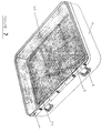
- a lining 20 is attached to the shell at the beadings 16 and 18 and glued with adhesive to the inner surfaces of the shells 4 and 6.
- Figures 2 and 3 show how the beading 8 extends around the periphery of the suitcase with one discontinuity at the hinge 22.
- the beading comprises a length 26 of low density polyethylene with a conductive wire 28 embedded in it.
- the metal wire is typically of mild steel which may have a resistivity of around 40 x 10 ⁇ 6 ⁇ cm ⁇ 1.
- the beading is extruded together with the conductive wire.
- the beading 8 can be extruded in any chosen shape to fit with the intended groove.
- the pre-melted beading can be seen with the conductive metal wire 28 embedded at 0.05mm from the surface of the beading.
- Figure 6 which is a section through the wall of the suitcase after the beadings 8,12 and 14 have been joined to the shell of the suitcase by resistance heating.
- reference numeral 28 indicates the area of material of the beading and shell which has melted and fused.
- the conductive wire (not shown) remains embedded within the fused material.
- the three beadings 8, 12 and 14 are each of a shape and configuration to fit the appropriate groove.
- the beading is L-shaped in cross-section.
- the transverse arm of the L-shape is thicker than the upright arm, but in beading 12 the arms are of generally equal thickness.
- the conductive wire 28 is located at the surface of one of the arms of the L-shape in the pre-fused beading, in the thinner arm where there is a difference in thickness between the arms.
- Beading 8 forms an essentially watertight seal between the upper and lower shells to prevent water seeping into the suitcase.
- Beadings 12 and 14, as well as providing a cushion for the inner rim of the hard shell attach the edge of lining 20 to the hard shell, as will be described below.
- the shell is placed on an apparatus 32 such as that illustrated in Fig. 8 and the beading with the metal wire embedded is inserted into the channel 10.
- the exposed ends 30 of the metal wire are connected to respective positive and negative electrodes of a power source.
- a current is passed through the wire, it heats up due to the resistance to flow of current.
- the conductive material of the wire can be selected for its resistivity.
- a typical resistivity of a mild steel wire useful in the invention is 40 x 10 ⁇ 6 ⁇ cm ⁇ 1.
- the heat generated causes the thermoplastic material of the beading and of the shell to melt locally and when the material is then allowed to cool the two materials become partly fused. In this way the beading 8 is effectively heat sealed to the shell and a band is formed.
- the exposed ends of the wire can be cut away close to the rib.
- a similar method is used to attach the beadings 12 and 14 to their respective shells, and to attach the edge of the lining.
- the edge of the material material of the lining has thermoplastic properties.
- the edge of the lining is trapped between the beading 12 or 14 and the shell 4 or 6 when the beading is inserted into the groove 16 or 18.
- the exposed ends 30 of the wire 28 are connected to the power supply and a current passed to heat the wire.
- the edge of the lining is heated so that it partially melts and fuses with the plastic of the shell and beading on cooling. Again the exposed ends of the wire can be cut away.
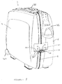
- FIG. 1 an article of luggage according to the present invention is shown which has a carrying handle 38, locks 24, castor wheels 40.
- the two shells 4 and 6 are hinged together by hinge 22.
- a pulling handle 36 is hinged to the shell 6 so that it can extend from the shell in use and can lie flat against the shell at other times.
Abstract
Description
- The present invention relates to a heat sealing process. In particular it relates to a heat sealing process for joining thermoplastic materials by resistance heating. In a particular embodiment, the invention relates to a method of joining a thermoplastic beading, to a luggage case (e.g. a suitcase, briefcase), and also relates to the piece of luggage so formed.
- In a prior art heat sealing process, the EMAWELD process, a thermoplastic matrix loaded with ferromagnetic powder is extruded as a strip and placed between two other plastics surfaces to be fused. The extruded strip is heated by exposing it to a high frequency alternating current and the adjacent plastics surfaces are thus also heated to a temperature at which they fuse with the EMAWELD strip, or with each other. There are disadvantages associated with this method. For example, it is difficult to extrude the plastic when it is loaded with ferromagnetic material, and the whole process is expensive to perform.
- In certain applications, it would be extremely desirable to be able to seal a plastic strip to another thermoplastics material cheaply and easily. One such application is that of sealing a plastic beading to the hard shell of a suitcase. The plastic beading acts as a water-tight seal to prevent water seeping into the suitcase or as a cushion when the suitcase is closed and the two shells came together. The beading also helps to prevent dust and dirt entering the suitcase.
- In more detail, so-called hard side luggage which is typically made of polypropylene or polyethylene often has a plastic beading fitted into grooves around the periphery of the upper and lower shells that make up the suitcase. The plastic beading is made of a soft plastics material, for example, polypropylene, low density polyethylene or ethylvinyl acetate, so that it acts as a cushion. The beading may also be coloured for a pleasing aesthetic effect. Until now, this beading has been attached to the suitcase using adhesives, screws or rivets. This method of fixing is time consuming, labour intensive and therefore expensive. The use of adhesives can give a messy result and screws and rivets tend to look untidy in the finished article. In addition, screws and rivets may cause damage to clothes and can cause injury to the user. They may also become detached from the beading and will then need replacing.
- Moulded or hard-side luggage does not usually have an inner lining of cloth or other fabric because there are no frames to conceal the edges of the lining. If a lining is required, a frame will need to be attached for this purpose, with screws or rivets. Again this gives an untidy appearance, and the method of attachment is time-consuming.
- The present invention seeks to provide a method for joining thermoplastics and which can in an exemplary embodiment be used to attach beading to suitcases. The method can also be utilised to attach a lining to a hard shell article of luggage.
- In a first aspect the invention provides a method of joining at least two thermoplastic materials wherein at least one of the materials has a conductive material embedded within it which method comprises suitably orienting the thermoplastics materials, and applying a current to the conductive material, whereby localised resistance heating causes the thermoplastic materials to melt locally and to at least partially fuse to join the thermoplastic materials. Preferably the materials become fused when they are cooled, to form a bond.
- Preferably the conductive material is wholly embedded in the thermoplastic material, although it may be embedded near to the surface of the thermoplastic material. Preferably the conductive wire is embedded just below the surface, for example, at a distance of around 0.05mm from the surface. Alternatively, part of the conductive material may be exposed to the exterior of the surface. Preferably the conductive material is embedded near to or exposed at the surface of the thermoplastic material which is intended to be joined to another thermoplastic material.
- Preferably the method comprises a first step of extruding a length of a first thermoplastics material together with a length of a conductive material whereby the conductive material is embedded in the thermoplastics material. Typically, the conductive material is a wire, for example a metal wire, and a length of thermoplastics material in the form of a beading may be extruded together with the conductive wire to embed the wire therein. The beading may be L-shaped and the arms of the "L" may be of equal or unequal thickness.
- In a specific embodiment the method comprises inserting the beading of thermoplastic material with the embedded length of conductive material into a channel in a hard shell of an article of luggage, and passing a current through the length of conductive material whereby the plastics material of the beading and luggage case shell locally melt and fuse, thereby to attach the beading to the luggage case shell.
- Typically, the channel will be a groove in an outwardly projecting rib extending around the periphery of one or both of the hard shells of the article of luggage.
- Advantageously the method further includes trapping the edge of a lining between the beading and hard shell, whereby when a current is passed through the conductive material, the edge of the lining also melts and fuses with the beading and/or shell. The remainder of the lining may be fixed, for example by an adhesive, with rivets or screws, or other conventional means, to the inside surface of the hard shell. The lining may be a sheet or woven fabric.
- Preferably the trapping of the edge of the lining is carried out by trapping the edge of the lining between a second beading and a second channel of the hard shell. Usually, this second channel will be a second groove in the outwardly projecting rib which extends around the periphery of the hard shell. The second groove will usually be the inner groove, so that the first groove contains the beading which acts as a seal, and the second, inner groove contains the beading which attaches, by trapping, the shell lining.
- In a further aspect, the invention provides a hard side luggage case which comprises at least two hard shells, at least one shell having around its periphery which in the closed luggage case abuts the other hard shell a plastic beading, part of which is fused with the periphery of the shell to attach it to the shell.
- Preferably the plastic beading sits in and is fused to a channel in a rib which projects outwardly from and extends peripherally around the hard shell of the luggage case. More preferably, the channel is a groove in the rib.
- One or both of the hard shells of the luggage case may also have a lining. The edge of the lining may be trapped between and fused to one or both of the beading and the hard shell, to fix the lining to the shell.
- Advantageously the remainder of the lining may be fixed, for example by an adhesive, with rivets or screws, or other conventional means, to the inside surface of the hard shell. The advantages of attaching the lining using this heat sealing method are that it gives a neat finish, and edge peeling is avoided.
- Typically the hard shell will be formed of polypropylene or polyethylene and the plastic beading will be polypropylene, low density polyethylene, ethylvinyl acetate or some other suitable material. Such a material may be selected for its compatibility in fusing with the material of the shell.
- Typically the plastic beading sits in a groove provided in a hard plastic rib which projects outwardly from the periphery of one or both of the shells. The luggage case provided by the present invention may have a beading or lining attached according to any of the methods mentioned above.
- A specific embodiment of the invention will now be described, by way of example only, and with reference to the accompanying drawings in which,
- Fig. 1 is a perspective view of a luggage case, in this case a suitcase, exemplifying one aspect of the invention, and showing one part of a side wall in section;
- Fig. 2 is a view from above of the suitcase;
- Fig. 3 is a view from below of the suitcase;
- Fig. 4 is a view of a plastic beading with a wire embedded in it;
- Fig. 5 is a view of a second plastic beading with a wire embedded in it;
- Fig. 6 is a section through part of the suitcase at the point where the upper and lower shells meet when the suitcase is closed;
- Fig. 7 is a perspective view of the base shell of the suitcase;
- Fig. 8 shows the shell of the suitcase mounted on a machine tool for carrying out a method according to the invention.
- In Fig. 1 a hard side suitcase is indicated generally at 2 and which has two
shells plastic beading 8 is fixed in achannel 10 around the periphery of an outwardly projectingrib 17 theupper shell 4. The otherplastic beadings respective channels ribs 17 and 19 (see Fig. 6) projecting from the upper and lower shells respectively. Alining 20 is attached to the shell at thebeadings shells beading 8 extends around the periphery of the suitcase with one discontinuity at thehinge 22. - As can be seen more clearly in Figures 4 and 5, the beading comprises a
length 26 of low density polyethylene with aconductive wire 28 embedded in it. The metal wire is typically of mild steel which may have a resistivity of around 40 x 10⁻⁶ Ω cm⁻¹. During manufacture, the beading is extruded together with the conductive wire. Thebeading 8 can be extruded in any chosen shape to fit with the intended groove. In Figs. 4 and 5 the pre-melted beading can be seen with theconductive metal wire 28 embedded at 0.05mm from the surface of the beading. - In Figure 6 which is a section through the wall of the suitcase after the
beadings reference numeral 28 indicates the area of material of the beading and shell which has melted and fused. The conductive wire (not shown) remains embedded within the fused material. - The three
beadings beadings beading 12 the arms are of generally equal thickness. Theconductive wire 28 is located at the surface of one of the arms of the L-shape in the pre-fused beading, in the thinner arm where there is a difference in thickness between the arms. -
Beading 8 forms an essentially watertight seal between the upper and lower shells to prevent water seeping into the suitcase. Beadings 12 and 14, as well as providing a cushion for the inner rim of the hard shell attach the edge of lining 20 to the hard shell, as will be described below. - To fix the
beading 8 to theshell 4, the shell is placed on anapparatus 32 such as that illustrated in Fig. 8 and the beading with the metal wire embedded is inserted into thechannel 10. The exposed ends 30 of the metal wire are connected to respective positive and negative electrodes of a power source. When a current is passed through the wire, it heats up due to the resistance to flow of current. The conductive material of the wire can be selected for its resistivity. A typical resistivity of a mild steel wire useful in the invention is 40 x 10⁻⁶ Ω cm⁻¹. The heat generated causes the thermoplastic material of the beading and of the shell to melt locally and when the material is then allowed to cool the two materials become partly fused. In this way thebeading 8 is effectively heat sealed to the shell and a band is formed. The exposed ends of the wire can be cut away close to the rib. - A similar method is used to attach the
beadings shell groove wire 28 are connected to the power supply and a current passed to heat the wire. This time, as well as the beading and shell (specifically the rib 34) the edge of the lining is heated so that it partially melts and fuses with the plastic of the shell and beading on cooling. Again the exposed ends of the wire can be cut away. In this way the edges of the lining are concealed underneath the beading, and a tidy and aesthetically pleasing appearance results. The fused bond is long-lasting and this method of attaching the lining is easier and cheaper than fixing with screws or rivets. The size of the sheet which forms the lining 20 can be exactly determined so that once the edges have been attached to the shell the remainder of the lining has a very close fit with the shell. The remainder of the lining can be attached to the shell either before or after the edges are fixed, and this may be done using any conventional means such as adhesives, screws or rivets.
Referring to Figures 1, 2 and 3 an article of luggage according to the present invention is shown which has a carryinghandle 38, locks 24,castor wheels 40. The twoshells hinge 22. A pullinghandle 36 is hinged to theshell 6 so that it can extend from the shell in use and can lie flat against the shell at other times.
Claims (12)
- A method of joining at least two thermoplastic materials wherein at least one of the materials has a conductive material embedded within it which method comprises suitably the thermoplastic materials to be adjacent to each other, and applying a current to the conductive material whereby localised resistance heating causes the thermoplastic materials to melt locally and to at least partially fuse to join the thermoplastics materials.
- A method according to claim 1 which further comprises a first step of extruding a length of a first plastics material together with a length of a conductive material whereby the conductive material is embedded in the thermoplastics material.
- A method according to claim 1 or 2 wherein the conductive material is a wire.
- A method according to claim 2 or 3 wherein a beading of thermoplastic material is extruded together with the conductive wire to embed the wire therein.
- A method of attaching a beading to a luggage case which comprises orienting a beading having a length of conductive material embedded therein in the desired location on a hard shell of the luggage case, and passing a current through the wire whereby the material of the thermoplastic beading and luggage case shell melt and fuse locally, to attach the bead to the luggage case shell.
- A method according to claim 5 which further includes trapping the edge of a lining between the beading and hard shell, whereby when a current is passed through the wire, the edge of the lining also melts and fuses with the bead and/or shell.
- A method according to claim 6 which further comprises fixing the remainder of the lining to the inside of the hard shell.
- A method according to claim 5, 6 or 7 wherein the desired location is a channel into which the beading is inserted to orient it on the hard shell.
- A hard side luggage case which comprises at least two hard shells, at least one hard shell having around its periphery which in the closed luggage case abuts the other hard shell a plastics beading, part of which is fused with the periphery of the shell to attach it to the shell.
- A hard side luggage case which comprises at least two hard shells, at least one hard shell having around its periphery a plastics beading, part of which is fused with the periphery of the shell and the edge of a lining for the shell to attach the beading and lining to the shell.
- A hard side luggage case according to claim 10 wherein the remainder of the lining is closely fitted and attached to the shell on its inner surface.
- A hard-side shell for a luggage case which has a beading attached in a groove around its periphery, the beading having been attached in a method according to any of claims 5 to 7.
Priority Applications (3)
| Application Number | Priority Date | Filing Date | Title |
|---|---|---|---|
| DE69311090T DE69311090T2 (en) | 1993-03-19 | 1993-03-19 | Hot welding process and travel case |
| EP93302104A EP0615833B1 (en) | 1993-03-19 | 1993-03-19 | A heat sealing method and luggage case |
| US08/210,892 US5458718A (en) | 1993-03-19 | 1994-03-18 | Heat sealing method for making a luggage case |
Applications Claiming Priority (1)
| Application Number | Priority Date | Filing Date | Title |
|---|---|---|---|
| EP93302104A EP0615833B1 (en) | 1993-03-19 | 1993-03-19 | A heat sealing method and luggage case |
Publications (2)
| Publication Number | Publication Date |
|---|---|
| EP0615833A1 true EP0615833A1 (en) | 1994-09-21 |
| EP0615833B1 EP0615833B1 (en) | 1997-05-28 |
Family
ID=8214349
Family Applications (1)
| Application Number | Title | Priority Date | Filing Date |
|---|---|---|---|
| EP93302104A Expired - Lifetime EP0615833B1 (en) | 1993-03-19 | 1993-03-19 | A heat sealing method and luggage case |
Country Status (3)
| Country | Link |
|---|---|
| US (1) | US5458718A (en) |
| EP (1) | EP0615833B1 (en) |
| DE (1) | DE69311090T2 (en) |
Cited By (3)
| Publication number | Priority date | Publication date | Assignee | Title |
|---|---|---|---|---|
| DE19913500A1 (en) * | 1999-03-25 | 2000-09-28 | Mahle Filtersysteme Gmbh | Method for connecting two plastic components |
| EP1867246A1 (en) * | 2006-06-16 | 2007-12-19 | VALIGERIA RONCATO S.p.A. | Lightweight structured suitcase |
| EP2168449A1 (en) * | 2008-09-30 | 2010-03-31 | VALIGERIA RONCATO S.p.A. | Suitcase |
Families Citing this family (64)
| Publication number | Priority date | Publication date | Assignee | Title |
|---|---|---|---|---|
| FR2652928B1 (en) | 1989-10-05 | 1994-07-29 | Diadix Sa | INTERACTIVE LOCAL INTERVENTION SYSTEM WITHIN A AREA OF A NON-HOMOGENEOUS STRUCTURE. |
| US5913820A (en) | 1992-08-14 | 1999-06-22 | British Telecommunications Public Limited Company | Position location system |
| US5592939A (en) | 1995-06-14 | 1997-01-14 | Martinelli; Michael A. | Method and system for navigating a catheter probe |
| US6003646A (en) * | 1997-08-07 | 1999-12-21 | Patagonia, Inc. | Method for manufacturing soft cloth durable luggage |
| US6226548B1 (en) | 1997-09-24 | 2001-05-01 | Surgical Navigation Technologies, Inc. | Percutaneous registration apparatus and method for use in computer-assisted surgical navigation |
| US6348058B1 (en) | 1997-12-12 | 2002-02-19 | Surgical Navigation Technologies, Inc. | Image guided spinal surgery guide, system, and method for use thereof |
| US6477400B1 (en) | 1998-08-20 | 2002-11-05 | Sofamor Danek Holdings, Inc. | Fluoroscopic image guided orthopaedic surgery system with intraoperative registration |
| US6470207B1 (en) | 1999-03-23 | 2002-10-22 | Surgical Navigation Technologies, Inc. | Navigational guidance via computer-assisted fluoroscopic imaging |
| US6491699B1 (en) | 1999-04-20 | 2002-12-10 | Surgical Navigation Technologies, Inc. | Instrument guidance method and system for image guided surgery |
| US6381485B1 (en) | 1999-10-28 | 2002-04-30 | Surgical Navigation Technologies, Inc. | Registration of human anatomy integrated for electromagnetic localization |
| US7366562B2 (en) | 2003-10-17 | 2008-04-29 | Medtronic Navigation, Inc. | Method and apparatus for surgical navigation |
| US11331150B2 (en) | 1999-10-28 | 2022-05-17 | Medtronic Navigation, Inc. | Method and apparatus for surgical navigation |
| US6499488B1 (en) | 1999-10-28 | 2002-12-31 | Winchester Development Associates | Surgical sensor |
| US8644907B2 (en) | 1999-10-28 | 2014-02-04 | Medtronic Navigaton, Inc. | Method and apparatus for surgical navigation |
| US8239001B2 (en) | 2003-10-17 | 2012-08-07 | Medtronic Navigation, Inc. | Method and apparatus for surgical navigation |
| US6493573B1 (en) | 1999-10-28 | 2002-12-10 | Winchester Development Associates | Method and system for navigating a catheter probe in the presence of field-influencing objects |
| US6474341B1 (en) | 1999-10-28 | 2002-11-05 | Surgical Navigation Technologies, Inc. | Surgical communication and power system |
| US6725080B2 (en) | 2000-03-01 | 2004-04-20 | Surgical Navigation Technologies, Inc. | Multiple cannula image guided tool for image guided procedures |
| US6535756B1 (en) | 2000-04-07 | 2003-03-18 | Surgical Navigation Technologies, Inc. | Trajectory storage apparatus and method for surgical navigation system |
| US7085400B1 (en) | 2000-06-14 | 2006-08-01 | Surgical Navigation Technologies, Inc. | System and method for image based sensor calibration |
| US6636757B1 (en) | 2001-06-04 | 2003-10-21 | Surgical Navigation Technologies, Inc. | Method and apparatus for electromagnetic navigation of a surgical probe near a metal object |
| US6947786B2 (en) | 2002-02-28 | 2005-09-20 | Surgical Navigation Technologies, Inc. | Method and apparatus for perspective inversion |
| US6990368B2 (en) | 2002-04-04 | 2006-01-24 | Surgical Navigation Technologies, Inc. | Method and apparatus for virtual digital subtraction angiography |
| US7998062B2 (en) | 2004-03-29 | 2011-08-16 | Superdimension, Ltd. | Endoscope structures and techniques for navigating to a target in branched structure |
| US7599730B2 (en) | 2002-11-19 | 2009-10-06 | Medtronic Navigation, Inc. | Navigation system for cardiac therapies |
| US7697972B2 (en) | 2002-11-19 | 2010-04-13 | Medtronic Navigation, Inc. | Navigation system for cardiac therapies |
| US7542791B2 (en) | 2003-01-30 | 2009-06-02 | Medtronic Navigation, Inc. | Method and apparatus for preplanning a surgical procedure |
| US7660623B2 (en) | 2003-01-30 | 2010-02-09 | Medtronic Navigation, Inc. | Six degree of freedom alignment display for medical procedures |
| US7313430B2 (en) | 2003-08-28 | 2007-12-25 | Medtronic Navigation, Inc. | Method and apparatus for performing stereotactic surgery |
| EP2316328B1 (en) | 2003-09-15 | 2012-05-09 | Super Dimension Ltd. | Wrap-around holding device for use with bronchoscopes |
| ES2432616T3 (en) | 2003-09-15 | 2013-12-04 | Covidien Lp | Accessory system for use with bronchoscopes |
| US7835778B2 (en) | 2003-10-16 | 2010-11-16 | Medtronic Navigation, Inc. | Method and apparatus for surgical navigation of a multiple piece construct for implantation |
| US7840253B2 (en) | 2003-10-17 | 2010-11-23 | Medtronic Navigation, Inc. | Method and apparatus for surgical navigation |
| US8764725B2 (en) | 2004-02-09 | 2014-07-01 | Covidien Lp | Directional anchoring mechanism, method and applications thereof |
| US7567834B2 (en) | 2004-05-03 | 2009-07-28 | Medtronic Navigation, Inc. | Method and apparatus for implantation between two vertebral bodies |
| US7835784B2 (en) | 2005-09-21 | 2010-11-16 | Medtronic Navigation, Inc. | Method and apparatus for positioning a reference frame |
| US9168102B2 (en) | 2006-01-18 | 2015-10-27 | Medtronic Navigation, Inc. | Method and apparatus for providing a container to a sterile environment |
| US8112292B2 (en) | 2006-04-21 | 2012-02-07 | Medtronic Navigation, Inc. | Method and apparatus for optimizing a therapy |
| US8660635B2 (en) | 2006-09-29 | 2014-02-25 | Medtronic, Inc. | Method and apparatus for optimizing a computer assisted surgical procedure |
| US8905920B2 (en) | 2007-09-27 | 2014-12-09 | Covidien Lp | Bronchoscope adapter and method |
| WO2009122273A2 (en) | 2008-04-03 | 2009-10-08 | Superdimension, Ltd. | Magnetic interference detection system and method |
| US8473032B2 (en) | 2008-06-03 | 2013-06-25 | Superdimension, Ltd. | Feature-based registration method |
| US8218847B2 (en) | 2008-06-06 | 2012-07-10 | Superdimension, Ltd. | Hybrid registration method |
| US8932207B2 (en) | 2008-07-10 | 2015-01-13 | Covidien Lp | Integrated multi-functional endoscopic tool |
| US8165658B2 (en) | 2008-09-26 | 2012-04-24 | Medtronic, Inc. | Method and apparatus for positioning a guide relative to a base |
| US8175681B2 (en) | 2008-12-16 | 2012-05-08 | Medtronic Navigation Inc. | Combination of electromagnetic and electropotential localization |
| US8611984B2 (en) | 2009-04-08 | 2013-12-17 | Covidien Lp | Locatable catheter |
| US8494613B2 (en) | 2009-08-31 | 2013-07-23 | Medtronic, Inc. | Combination localization system |
| US8494614B2 (en) | 2009-08-31 | 2013-07-23 | Regents Of The University Of Minnesota | Combination localization system |
| WO2011159834A1 (en) | 2010-06-15 | 2011-12-22 | Superdimension, Ltd. | Locatable expandable working channel and method |
| US10952593B2 (en) | 2014-06-10 | 2021-03-23 | Covidien Lp | Bronchoscope adapter |
| US10426555B2 (en) | 2015-06-03 | 2019-10-01 | Covidien Lp | Medical instrument with sensor for use in a system and method for electromagnetic navigation |
| US9962134B2 (en) | 2015-10-28 | 2018-05-08 | Medtronic Navigation, Inc. | Apparatus and method for maintaining image quality while minimizing X-ray dosage of a patient |
| US10478254B2 (en) | 2016-05-16 | 2019-11-19 | Covidien Lp | System and method to access lung tissue |
| US10418705B2 (en) | 2016-10-28 | 2019-09-17 | Covidien Lp | Electromagnetic navigation antenna assembly and electromagnetic navigation system including the same |
| US10751126B2 (en) | 2016-10-28 | 2020-08-25 | Covidien Lp | System and method for generating a map for electromagnetic navigation |
| US10638952B2 (en) | 2016-10-28 | 2020-05-05 | Covidien Lp | Methods, systems, and computer-readable media for calibrating an electromagnetic navigation system |
| US10517505B2 (en) | 2016-10-28 | 2019-12-31 | Covidien Lp | Systems, methods, and computer-readable media for optimizing an electromagnetic navigation system |
| US10615500B2 (en) | 2016-10-28 | 2020-04-07 | Covidien Lp | System and method for designing electromagnetic navigation antenna assemblies |
| US10446931B2 (en) | 2016-10-28 | 2019-10-15 | Covidien Lp | Electromagnetic navigation antenna assembly and electromagnetic navigation system including the same |
| US10792106B2 (en) | 2016-10-28 | 2020-10-06 | Covidien Lp | System for calibrating an electromagnetic navigation system |
| US10722311B2 (en) | 2016-10-28 | 2020-07-28 | Covidien Lp | System and method for identifying a location and/or an orientation of an electromagnetic sensor based on a map |
| US11219489B2 (en) | 2017-10-31 | 2022-01-11 | Covidien Lp | Devices and systems for providing sensors in parallel with medical tools |
| EP3646751B1 (en) | 2018-10-31 | 2021-06-16 | Samsonite IP Holdings S.à r.l. | Luggage article including a burst resistant rim |
Citations (10)
| Publication number | Priority date | Publication date | Assignee | Title |
|---|---|---|---|---|
| US2969891A (en) | 1958-03-12 | 1961-01-31 | Michael C Presnick | Case finishing molding |
| US3047703A (en) * | 1959-03-26 | 1962-07-31 | Honeywell Regulator Co | Sealing apparatus |
| DE1284618B (en) * | 1965-02-13 | 1968-12-05 | Mannesmann Ag | Method for reinforcing flanges formed by boring pipes made of high molecular weight polyethylene |
| GB1148044A (en) * | 1965-12-03 | 1969-04-10 | Draftex G M B H | A method of securing fittings to motor vehicles |
| FR2156472A1 (en) * | 1971-10-21 | 1973-06-01 | Calor Sa | Welding together plastic articles - with a hot wire remaining in the assembly |
| EP0019497A1 (en) * | 1979-04-13 | 1980-11-26 | Philippe Lhotellier | Method for the tight fastening of a rigid frame to the rim of a shell and closed containers |
| US4376005A (en) * | 1980-09-22 | 1983-03-08 | Dayco Corporation | Method of making hose |
| EP0221215A1 (en) * | 1985-10-31 | 1987-05-13 | SAMSONITE CORPORATION (a Delaware corporation) | Luggage case |
| EP0402201A2 (en) * | 1989-06-09 | 1990-12-12 | Boulet-D'auria, Terlizzi & Cie | Wire with shaped coating, especially for making an electro-fusion insert |
| US4993585A (en) | 1989-01-12 | 1991-02-19 | Mcmahon William | Encapsulated case edging |
Family Cites Families (6)
| Publication number | Priority date | Publication date | Assignee | Title |
|---|---|---|---|---|
| US2758682A (en) * | 1954-09-16 | 1956-08-14 | Shwayder Bros Inc | Luggage moldings |
| US3756881A (en) * | 1971-01-11 | 1973-09-04 | St Denman | Method of coupling articles of unlike materials |
| FR2353381A1 (en) * | 1976-06-03 | 1977-12-30 | Pont A Mousson | ASSEMBLY PROCESS BY WELDING PLASTIC TUBES AND CONNECTING FOR SUCH ASSEMBLY |
| GB1592055A (en) * | 1978-03-20 | 1981-07-01 | Treasury Solicitor For The Aff | Luggage cases |
| US4436988A (en) * | 1982-03-01 | 1984-03-13 | R & G Sloane Mfg. Co., Inc. | Spiral bifilar welding sleeve |
| IT1250898B (en) * | 1991-12-24 | 1995-04-21 | Fiat Auto Spa | FUEL TANK FOR MOTOR VEHICLES AND PROCEDURE FOR ITS REALIZATION. |
-
1993
- 1993-03-19 EP EP93302104A patent/EP0615833B1/en not_active Expired - Lifetime
- 1993-03-19 DE DE69311090T patent/DE69311090T2/en not_active Expired - Fee Related
-
1994
- 1994-03-18 US US08/210,892 patent/US5458718A/en not_active Expired - Fee Related
Patent Citations (10)
| Publication number | Priority date | Publication date | Assignee | Title |
|---|---|---|---|---|
| US2969891A (en) | 1958-03-12 | 1961-01-31 | Michael C Presnick | Case finishing molding |
| US3047703A (en) * | 1959-03-26 | 1962-07-31 | Honeywell Regulator Co | Sealing apparatus |
| DE1284618B (en) * | 1965-02-13 | 1968-12-05 | Mannesmann Ag | Method for reinforcing flanges formed by boring pipes made of high molecular weight polyethylene |
| GB1148044A (en) * | 1965-12-03 | 1969-04-10 | Draftex G M B H | A method of securing fittings to motor vehicles |
| FR2156472A1 (en) * | 1971-10-21 | 1973-06-01 | Calor Sa | Welding together plastic articles - with a hot wire remaining in the assembly |
| EP0019497A1 (en) * | 1979-04-13 | 1980-11-26 | Philippe Lhotellier | Method for the tight fastening of a rigid frame to the rim of a shell and closed containers |
| US4376005A (en) * | 1980-09-22 | 1983-03-08 | Dayco Corporation | Method of making hose |
| EP0221215A1 (en) * | 1985-10-31 | 1987-05-13 | SAMSONITE CORPORATION (a Delaware corporation) | Luggage case |
| US4993585A (en) | 1989-01-12 | 1991-02-19 | Mcmahon William | Encapsulated case edging |
| EP0402201A2 (en) * | 1989-06-09 | 1990-12-12 | Boulet-D'auria, Terlizzi & Cie | Wire with shaped coating, especially for making an electro-fusion insert |
Cited By (6)
| Publication number | Priority date | Publication date | Assignee | Title |
|---|---|---|---|---|
| DE19913500A1 (en) * | 1999-03-25 | 2000-09-28 | Mahle Filtersysteme Gmbh | Method for connecting two plastic components |
| EP1867246A1 (en) * | 2006-06-16 | 2007-12-19 | VALIGERIA RONCATO S.p.A. | Lightweight structured suitcase |
| WO2007144137A1 (en) * | 2006-06-16 | 2007-12-21 | Valigeria Roncato S.P.A. | Lightweight structured suitcase |
| CN101489434B (en) * | 2006-06-16 | 2011-02-02 | 瓦利格拉·龙卡托公开有限公司 | Lightweight structured suitcase |
| EP2168449A1 (en) * | 2008-09-30 | 2010-03-31 | VALIGERIA RONCATO S.p.A. | Suitcase |
| ITMI20081740A1 (en) * | 2008-09-30 | 2010-04-01 | Valigeria Roncato Spa | SUITCASE |
Also Published As
| Publication number | Publication date |
|---|---|
| EP0615833B1 (en) | 1997-05-28 |
| DE69311090T2 (en) | 1997-10-16 |
| US5458718A (en) | 1995-10-17 |
| DE69311090D1 (en) | 1997-07-03 |
Similar Documents
| Publication | Publication Date | Title |
|---|---|---|
| EP0615833B1 (en) | A heat sealing method and luggage case | |
| EP1228713B1 (en) | Slide fastener and manufaturing method therefor | |
| EP1867246B1 (en) | Lightweight structured suitcase | |
| US4159728A (en) | Hot water bag | |
| US4174986A (en) | Method of forming a flexible tapered end for an extruded plastic molding strip | |
| JP2003511178A (en) | Method for making injection-molded luggage shell and bag made therefrom | |
| GB2275224A (en) | Welding method and luggage case | |
| JPH0288338A (en) | Decorative molding for car and manufacture thereof | |
| US11725455B2 (en) | Roller shade hem bar assembly | |
| AU617624B1 (en) | A zipper and a method for manufacturing a bag having the zipper | |
| BE1006752A3 (en) | Glove and method for manufacturing of such glove. | |
| JP2006117222A (en) | Glass molding for automobile | |
| GB2273734A (en) | Connecting channel-shaped strips | |
| CA1087379A (en) | Slide fastener with clear binder seal and method of manufacture | |
| US2936518A (en) | Method of forming a lamp shade | |
| US4026750A (en) | Sheathed soft-feel handle with concealed lapped ends and method of making same | |
| EP1433585A2 (en) | A framed panel and its process of forming | |
| JP3168369B2 (en) | Manufacturing method of weather strip for automobile | |
| US20200014142A1 (en) | Tough flexible resistant pouch with sealable sides used to protect the plugs and sockets of electric cords or other types of connections from the elements | |
| JPS60124239A (en) | Preparation of expanded product with skin material | |
| JPS5952049B2 (en) | Method of manufacturing equipment window device | |
| JPH01215617A (en) | Sun visor for vehicle | |
| JPH0380616B2 (en) | ||
| EP1296845B1 (en) | Glazing panel | |
| JPS6336933B2 (en) |
Legal Events
| Date | Code | Title | Description |
|---|---|---|---|
| PUAI | Public reference made under article 153(3) epc to a published international application that has entered the european phase |
Free format text: ORIGINAL CODE: 0009012 |
|
| AK | Designated contracting states |
Kind code of ref document: A1 Designated state(s): BE CH DE FR IT LI LU |
|
| RBV | Designated contracting states (corrected) |
Designated state(s): AT BE CH DE ES FR IT LI LU NL |
|
| 17P | Request for examination filed |
Effective date: 19950123 |
|
| 17Q | First examination report despatched |
Effective date: 19960116 |
|
| GRAG | Despatch of communication of intention to grant |
Free format text: ORIGINAL CODE: EPIDOS AGRA |
|
| GRAH | Despatch of communication of intention to grant a patent |
Free format text: ORIGINAL CODE: EPIDOS IGRA |
|
| GRAH | Despatch of communication of intention to grant a patent |
Free format text: ORIGINAL CODE: EPIDOS IGRA |
|
| 18W | Application withdrawn |
Withdrawal date: 19970113 |
|
| D18W | Application withdrawn (deleted) | ||
| RBV | Designated contracting states (corrected) |
Designated state(s): BE CH DE FR IT LI LU |
|
| GRAA | (expected) grant |
Free format text: ORIGINAL CODE: 0009210 |
|
| REG | Reference to a national code |
Ref country code: DE Ref legal event code: 8570 |
|
| AK | Designated contracting states |
Kind code of ref document: B1 Designated state(s): BE CH DE FR IT LI LU |
|
| REG | Reference to a national code |
Ref country code: CH Ref legal event code: EP |
|
| REF | Corresponds to: |
Ref document number: 69311090 Country of ref document: DE Date of ref document: 19970703 |
|
| ET | Fr: translation filed | ||
| PG25 | Lapsed in a contracting state [announced via postgrant information from national office to epo] |
Ref country code: LU Free format text: LAPSE BECAUSE OF NON-PAYMENT OF DUE FEES Effective date: 19980319 |
|
| PLBE | No opposition filed within time limit |
Free format text: ORIGINAL CODE: 0009261 |
|
| STAA | Information on the status of an ep patent application or granted ep patent |
Free format text: STATUS: NO OPPOSITION FILED WITHIN TIME LIMIT |
|
| 26N | No opposition filed | ||
| PGFP | Annual fee paid to national office [announced via postgrant information from national office to epo] |
Ref country code: DE Payment date: 20080728 Year of fee payment: 16 Ref country code: CH Payment date: 20080725 Year of fee payment: 16 |
|
| PGFP | Annual fee paid to national office [announced via postgrant information from national office to epo] |
Ref country code: IT Payment date: 20080728 Year of fee payment: 16 Ref country code: FR Payment date: 20080725 Year of fee payment: 16 |
|
| PGFP | Annual fee paid to national office [announced via postgrant information from national office to epo] |
Ref country code: BE Payment date: 20080729 Year of fee payment: 16 |
|
| BERE | Be: lapsed |
Owner name: *VIP INDUSTRIES LTD Effective date: 20090331 |
|
| REG | Reference to a national code |
Ref country code: CH Ref legal event code: PL |
|
| REG | Reference to a national code |
Ref country code: FR Ref legal event code: ST Effective date: 20091130 |
|
| PG25 | Lapsed in a contracting state [announced via postgrant information from national office to epo] |
Ref country code: LI Free format text: LAPSE BECAUSE OF NON-PAYMENT OF DUE FEES Effective date: 20090331 Ref country code: DE Free format text: LAPSE BECAUSE OF NON-PAYMENT OF DUE FEES Effective date: 20091001 Ref country code: CH Free format text: LAPSE BECAUSE OF NON-PAYMENT OF DUE FEES Effective date: 20090331 |
|
| PG25 | Lapsed in a contracting state [announced via postgrant information from national office to epo] |
Ref country code: BE Free format text: LAPSE BECAUSE OF NON-PAYMENT OF DUE FEES Effective date: 20090331 |
|
| PG25 | Lapsed in a contracting state [announced via postgrant information from national office to epo] |
Ref country code: FR Free format text: LAPSE BECAUSE OF NON-PAYMENT OF DUE FEES Effective date: 20091123 |
|
| PG25 | Lapsed in a contracting state [announced via postgrant information from national office to epo] |
Ref country code: IT Free format text: LAPSE BECAUSE OF NON-PAYMENT OF DUE FEES Effective date: 20090319 |