EP0615480B1 - Improvements relating to friction welding - Google Patents
Improvements relating to friction welding Download PDFInfo
- Publication number
- EP0615480B1 EP0615480B1 EP92923936A EP92923936A EP0615480B1 EP 0615480 B1 EP0615480 B1 EP 0615480B1 EP 92923936 A EP92923936 A EP 92923936A EP 92923936 A EP92923936 A EP 92923936A EP 0615480 B1 EP0615480 B1 EP 0615480B1
- Authority
- EP
- European Patent Office
- Prior art keywords
- probe
- workpieces
- joint
- joint region
- plasticised
- Prior art date
- Legal status (The legal status is an assumption and is not a legal conclusion. Google has not performed a legal analysis and makes no representation as to the accuracy of the status listed.)
- Expired - Lifetime
Links
- 238000003466 welding Methods 0.000 title description 9
- 239000000463 material Substances 0.000 claims abstract description 78
- 238000000034 method Methods 0.000 claims abstract description 56
- 239000000523 sample Substances 0.000 claims abstract description 55
- 230000033001 locomotion Effects 0.000 claims abstract description 21
- 238000005304 joining Methods 0.000 claims abstract description 11
- 125000004122 cyclic group Chemical group 0.000 claims abstract description 6
- 230000008933 bodily movement Effects 0.000 claims description 2
- 210000001503 joint Anatomy 0.000 description 20
- 238000010438 heat treatment Methods 0.000 description 14
- 239000012815 thermoplastic material Substances 0.000 description 10
- -1 aluminium silicon magnesium Chemical compound 0.000 description 7
- 238000001816 cooling Methods 0.000 description 7
- 239000004698 Polyethylene Substances 0.000 description 5
- 230000008901 benefit Effects 0.000 description 5
- 229920000573 polyethylene Polymers 0.000 description 5
- 239000004033 plastic Substances 0.000 description 4
- 229920003023 plastic Polymers 0.000 description 4
- 230000008569 process Effects 0.000 description 4
- 229910000838 Al alloy Inorganic materials 0.000 description 3
- 229910000831 Steel Inorganic materials 0.000 description 3
- 238000013459 approach Methods 0.000 description 3
- 239000011324 bead Substances 0.000 description 3
- 239000003365 glass fiber Substances 0.000 description 3
- 238000009987 spinning Methods 0.000 description 3
- 239000010959 steel Substances 0.000 description 3
- 229910000861 Mg alloy Inorganic materials 0.000 description 2
- 229910001315 Tool steel Inorganic materials 0.000 description 2
- 239000004411 aluminium Substances 0.000 description 2
- 229910052782 aluminium Inorganic materials 0.000 description 2
- XAGFODPZIPBFFR-UHFFFAOYSA-N aluminium Chemical compound [Al] XAGFODPZIPBFFR-UHFFFAOYSA-N 0.000 description 2
- 230000015572 biosynthetic process Effects 0.000 description 2
- 238000007596 consolidation process Methods 0.000 description 2
- 238000006073 displacement reaction Methods 0.000 description 2
- 239000007789 gas Substances 0.000 description 2
- 238000004519 manufacturing process Methods 0.000 description 2
- 238000002844 melting Methods 0.000 description 2
- 230000008018 melting Effects 0.000 description 2
- 229910052751 metal Inorganic materials 0.000 description 2
- 239000002184 metal Substances 0.000 description 2
- 230000003647 oxidation Effects 0.000 description 2
- 238000007254 oxidation reaction Methods 0.000 description 2
- 230000000149 penetrating effect Effects 0.000 description 2
- 239000011148 porous material Substances 0.000 description 2
- 238000009864 tensile test Methods 0.000 description 2
- 229920001169 thermoplastic Polymers 0.000 description 2
- 239000004416 thermosoftening plastic Substances 0.000 description 2
- 229910000851 Alloy steel Inorganic materials 0.000 description 1
- 229910045601 alloy Inorganic materials 0.000 description 1
- 239000000956 alloy Substances 0.000 description 1
- 230000015556 catabolic process Effects 0.000 description 1
- 150000001875 compounds Chemical class 0.000 description 1
- 238000004320 controlled atmosphere Methods 0.000 description 1
- 239000002178 crystalline material Substances 0.000 description 1
- 230000007547 defect Effects 0.000 description 1
- 238000006731 degradation reaction Methods 0.000 description 1
- 238000005553 drilling Methods 0.000 description 1
- 238000011156 evaluation Methods 0.000 description 1
- 239000000835 fiber Substances 0.000 description 1
- 238000011065 in-situ storage Methods 0.000 description 1
- 230000000977 initiatory effect Effects 0.000 description 1
- 230000007246 mechanism Effects 0.000 description 1
- 150000002739 metals Chemical class 0.000 description 1
- 239000000203 mixture Substances 0.000 description 1
- 238000011378 penetrating method Methods 0.000 description 1
- 230000035515 penetration Effects 0.000 description 1
- 230000002093 peripheral effect Effects 0.000 description 1
- 238000004023 plastic welding Methods 0.000 description 1
- 239000004810 polytetrafluoroethylene Substances 0.000 description 1
- 229920001343 polytetrafluoroethylene Polymers 0.000 description 1
- 238000002360 preparation method Methods 0.000 description 1
- 230000009467 reduction Effects 0.000 description 1
- 230000008439 repair process Effects 0.000 description 1
- 238000007789 sealing Methods 0.000 description 1
- 239000007790 solid phase Substances 0.000 description 1
- 238000003756 stirring Methods 0.000 description 1
- 230000001360 synchronised effect Effects 0.000 description 1
- 238000012360 testing method Methods 0.000 description 1
- 238000013519 translation Methods 0.000 description 1
- 229920006352 transparent thermoplastic Polymers 0.000 description 1
- 239000011800 void material Substances 0.000 description 1
Images


Classifications
-
- B—PERFORMING OPERATIONS; TRANSPORTING
- B29—WORKING OF PLASTICS; WORKING OF SUBSTANCES IN A PLASTIC STATE IN GENERAL
- B29C—SHAPING OR JOINING OF PLASTICS; SHAPING OF MATERIAL IN A PLASTIC STATE, NOT OTHERWISE PROVIDED FOR; AFTER-TREATMENT OF THE SHAPED PRODUCTS, e.g. REPAIRING
- B29C66/00—General aspects of processes or apparatus for joining preformed parts
- B29C66/80—General aspects of machine operations or constructions and parts thereof
- B29C66/81—General aspects of the pressing elements, i.e. the elements applying pressure on the parts to be joined in the area to be joined, e.g. the welding jaws or clamps
- B29C66/814—General aspects of the pressing elements, i.e. the elements applying pressure on the parts to be joined in the area to be joined, e.g. the welding jaws or clamps characterised by the design of the pressing elements, e.g. of the welding jaws or clamps
- B29C66/8141—General aspects of the pressing elements, i.e. the elements applying pressure on the parts to be joined in the area to be joined, e.g. the welding jaws or clamps characterised by the design of the pressing elements, e.g. of the welding jaws or clamps characterised by the surface geometry of the part of the pressing elements, e.g. welding jaws or clamps, coming into contact with the parts to be joined
- B29C66/81427—General aspects of the pressing elements, i.e. the elements applying pressure on the parts to be joined in the area to be joined, e.g. the welding jaws or clamps characterised by the design of the pressing elements, e.g. of the welding jaws or clamps characterised by the surface geometry of the part of the pressing elements, e.g. welding jaws or clamps, coming into contact with the parts to be joined comprising a single ridge, e.g. for making a weakening line; comprising a single tooth
- B29C66/81429—General aspects of the pressing elements, i.e. the elements applying pressure on the parts to be joined in the area to be joined, e.g. the welding jaws or clamps characterised by the design of the pressing elements, e.g. of the welding jaws or clamps characterised by the surface geometry of the part of the pressing elements, e.g. welding jaws or clamps, coming into contact with the parts to be joined comprising a single ridge, e.g. for making a weakening line; comprising a single tooth comprising a single tooth
-
- B—PERFORMING OPERATIONS; TRANSPORTING
- B23—MACHINE TOOLS; METAL-WORKING NOT OTHERWISE PROVIDED FOR
- B23K—SOLDERING OR UNSOLDERING; WELDING; CLADDING OR PLATING BY SOLDERING OR WELDING; CUTTING BY APPLYING HEAT LOCALLY, e.g. FLAME CUTTING; WORKING BY LASER BEAM
- B23K20/00—Non-electric welding by applying impact or other pressure, with or without the application of heat, e.g. cladding or plating
- B23K20/12—Non-electric welding by applying impact or other pressure, with or without the application of heat, e.g. cladding or plating the heat being generated by friction; Friction welding
- B23K20/122—Non-electric welding by applying impact or other pressure, with or without the application of heat, e.g. cladding or plating the heat being generated by friction; Friction welding using a non-consumable tool, e.g. friction stir welding
- B23K20/1245—Non-electric welding by applying impact or other pressure, with or without the application of heat, e.g. cladding or plating the heat being generated by friction; Friction welding using a non-consumable tool, e.g. friction stir welding characterised by the apparatus
- B23K20/1255—Tools therefor, e.g. characterised by the shape of the probe
-
- B—PERFORMING OPERATIONS; TRANSPORTING
- B23—MACHINE TOOLS; METAL-WORKING NOT OTHERWISE PROVIDED FOR
- B23K—SOLDERING OR UNSOLDERING; WELDING; CLADDING OR PLATING BY SOLDERING OR WELDING; CUTTING BY APPLYING HEAT LOCALLY, e.g. FLAME CUTTING; WORKING BY LASER BEAM
- B23K20/00—Non-electric welding by applying impact or other pressure, with or without the application of heat, e.g. cladding or plating
- B23K20/12—Non-electric welding by applying impact or other pressure, with or without the application of heat, e.g. cladding or plating the heat being generated by friction; Friction welding
- B23K20/122—Non-electric welding by applying impact or other pressure, with or without the application of heat, e.g. cladding or plating the heat being generated by friction; Friction welding using a non-consumable tool, e.g. friction stir welding
- B23K20/127—Non-electric welding by applying impact or other pressure, with or without the application of heat, e.g. cladding or plating the heat being generated by friction; Friction welding using a non-consumable tool, e.g. friction stir welding friction stir welding involving a mechanical connection
-
- B—PERFORMING OPERATIONS; TRANSPORTING
- B23—MACHINE TOOLS; METAL-WORKING NOT OTHERWISE PROVIDED FOR
- B23K—SOLDERING OR UNSOLDERING; WELDING; CLADDING OR PLATING BY SOLDERING OR WELDING; CUTTING BY APPLYING HEAT LOCALLY, e.g. FLAME CUTTING; WORKING BY LASER BEAM
- B23K20/00—Non-electric welding by applying impact or other pressure, with or without the application of heat, e.g. cladding or plating
- B23K20/12—Non-electric welding by applying impact or other pressure, with or without the application of heat, e.g. cladding or plating the heat being generated by friction; Friction welding
- B23K20/129—Non-electric welding by applying impact or other pressure, with or without the application of heat, e.g. cladding or plating the heat being generated by friction; Friction welding specially adapted for particular articles or workpieces
-
- B—PERFORMING OPERATIONS; TRANSPORTING
- B29—WORKING OF PLASTICS; WORKING OF SUBSTANCES IN A PLASTIC STATE IN GENERAL
- B29C—SHAPING OR JOINING OF PLASTICS; SHAPING OF MATERIAL IN A PLASTIC STATE, NOT OTHERWISE PROVIDED FOR; AFTER-TREATMENT OF THE SHAPED PRODUCTS, e.g. REPAIRING
- B29C65/00—Joining or sealing of preformed parts, e.g. welding of plastics materials; Apparatus therefor
- B29C65/02—Joining or sealing of preformed parts, e.g. welding of plastics materials; Apparatus therefor by heating, with or without pressure
- B29C65/06—Joining or sealing of preformed parts, e.g. welding of plastics materials; Apparatus therefor by heating, with or without pressure using friction, e.g. spin welding
- B29C65/0681—Joining or sealing of preformed parts, e.g. welding of plastics materials; Apparatus therefor by heating, with or without pressure using friction, e.g. spin welding created by a tool
-
- B—PERFORMING OPERATIONS; TRANSPORTING
- B29—WORKING OF PLASTICS; WORKING OF SUBSTANCES IN A PLASTIC STATE IN GENERAL
- B29C—SHAPING OR JOINING OF PLASTICS; SHAPING OF MATERIAL IN A PLASTIC STATE, NOT OTHERWISE PROVIDED FOR; AFTER-TREATMENT OF THE SHAPED PRODUCTS, e.g. REPAIRING
- B29C66/00—General aspects of processes or apparatus for joining preformed parts
- B29C66/01—General aspects dealing with the joint area or with the area to be joined
- B29C66/05—Particular design of joint configurations
- B29C66/10—Particular design of joint configurations particular design of the joint cross-sections
- B29C66/11—Joint cross-sections comprising a single joint-segment, i.e. one of the parts to be joined comprising a single joint-segment in the joint cross-section
- B29C66/114—Single butt joints
- B29C66/1142—Single butt to butt joints
-
- B—PERFORMING OPERATIONS; TRANSPORTING
- B29—WORKING OF PLASTICS; WORKING OF SUBSTANCES IN A PLASTIC STATE IN GENERAL
- B29C—SHAPING OR JOINING OF PLASTICS; SHAPING OF MATERIAL IN A PLASTIC STATE, NOT OTHERWISE PROVIDED FOR; AFTER-TREATMENT OF THE SHAPED PRODUCTS, e.g. REPAIRING
- B29C66/00—General aspects of processes or apparatus for joining preformed parts
- B29C66/01—General aspects dealing with the joint area or with the area to be joined
- B29C66/05—Particular design of joint configurations
- B29C66/10—Particular design of joint configurations particular design of the joint cross-sections
- B29C66/11—Joint cross-sections comprising a single joint-segment, i.e. one of the parts to be joined comprising a single joint-segment in the joint cross-section
- B29C66/116—Single bevelled joints, i.e. one of the parts to be joined being bevelled in the joint area
- B29C66/1162—Single bevel to bevel joints, e.g. mitre joints
-
- B—PERFORMING OPERATIONS; TRANSPORTING
- B29—WORKING OF PLASTICS; WORKING OF SUBSTANCES IN A PLASTIC STATE IN GENERAL
- B29C—SHAPING OR JOINING OF PLASTICS; SHAPING OF MATERIAL IN A PLASTIC STATE, NOT OTHERWISE PROVIDED FOR; AFTER-TREATMENT OF THE SHAPED PRODUCTS, e.g. REPAIRING
- B29C66/00—General aspects of processes or apparatus for joining preformed parts
- B29C66/01—General aspects dealing with the joint area or with the area to be joined
- B29C66/05—Particular design of joint configurations
- B29C66/10—Particular design of joint configurations particular design of the joint cross-sections
- B29C66/14—Particular design of joint configurations particular design of the joint cross-sections the joint having the same thickness as the thickness of the parts to be joined
-
- B—PERFORMING OPERATIONS; TRANSPORTING
- B29—WORKING OF PLASTICS; WORKING OF SUBSTANCES IN A PLASTIC STATE IN GENERAL
- B29C—SHAPING OR JOINING OF PLASTICS; SHAPING OF MATERIAL IN A PLASTIC STATE, NOT OTHERWISE PROVIDED FOR; AFTER-TREATMENT OF THE SHAPED PRODUCTS, e.g. REPAIRING
- B29C66/00—General aspects of processes or apparatus for joining preformed parts
- B29C66/40—General aspects of joining substantially flat articles, e.g. plates, sheets or web-like materials; Making flat seams in tubular or hollow articles; Joining single elements to substantially flat surfaces
- B29C66/41—Joining substantially flat articles ; Making flat seams in tubular or hollow articles
- B29C66/43—Joining a relatively small portion of the surface of said articles
-
- B—PERFORMING OPERATIONS; TRANSPORTING
- B29—WORKING OF PLASTICS; WORKING OF SUBSTANCES IN A PLASTIC STATE IN GENERAL
- B29C—SHAPING OR JOINING OF PLASTICS; SHAPING OF MATERIAL IN A PLASTIC STATE, NOT OTHERWISE PROVIDED FOR; AFTER-TREATMENT OF THE SHAPED PRODUCTS, e.g. REPAIRING
- B29C66/00—General aspects of processes or apparatus for joining preformed parts
- B29C66/70—General aspects of processes or apparatus for joining preformed parts characterised by the composition, physical properties or the structure of the material of the parts to be joined; Joining with non-plastics material
- B29C66/73—General aspects of processes or apparatus for joining preformed parts characterised by the composition, physical properties or the structure of the material of the parts to be joined; Joining with non-plastics material characterised by the intensive physical properties of the material of the parts to be joined, by the optical properties of the material of the parts to be joined, by the extensive physical properties of the parts to be joined, by the state of the material of the parts to be joined or by the material of the parts to be joined being a thermoplastic or a thermoset
- B29C66/737—General aspects of processes or apparatus for joining preformed parts characterised by the composition, physical properties or the structure of the material of the parts to be joined; Joining with non-plastics material characterised by the intensive physical properties of the material of the parts to be joined, by the optical properties of the material of the parts to be joined, by the extensive physical properties of the parts to be joined, by the state of the material of the parts to be joined or by the material of the parts to be joined being a thermoplastic or a thermoset characterised by the state of the material of the parts to be joined
- B29C66/7377—General aspects of processes or apparatus for joining preformed parts characterised by the composition, physical properties or the structure of the material of the parts to be joined; Joining with non-plastics material characterised by the intensive physical properties of the material of the parts to be joined, by the optical properties of the material of the parts to be joined, by the extensive physical properties of the parts to be joined, by the state of the material of the parts to be joined or by the material of the parts to be joined being a thermoplastic or a thermoset characterised by the state of the material of the parts to be joined amorphous, semi-crystalline or crystalline
- B29C66/73771—General aspects of processes or apparatus for joining preformed parts characterised by the composition, physical properties or the structure of the material of the parts to be joined; Joining with non-plastics material characterised by the intensive physical properties of the material of the parts to be joined, by the optical properties of the material of the parts to be joined, by the extensive physical properties of the parts to be joined, by the state of the material of the parts to be joined or by the material of the parts to be joined being a thermoplastic or a thermoset characterised by the state of the material of the parts to be joined amorphous, semi-crystalline or crystalline the to-be-joined area of at least one of the parts to be joined being amorphous
- B29C66/73772—General aspects of processes or apparatus for joining preformed parts characterised by the composition, physical properties or the structure of the material of the parts to be joined; Joining with non-plastics material characterised by the intensive physical properties of the material of the parts to be joined, by the optical properties of the material of the parts to be joined, by the extensive physical properties of the parts to be joined, by the state of the material of the parts to be joined or by the material of the parts to be joined being a thermoplastic or a thermoset characterised by the state of the material of the parts to be joined amorphous, semi-crystalline or crystalline the to-be-joined area of at least one of the parts to be joined being amorphous the to-be-joined areas of both parts to be joined being amorphous
-
- B—PERFORMING OPERATIONS; TRANSPORTING
- B29—WORKING OF PLASTICS; WORKING OF SUBSTANCES IN A PLASTIC STATE IN GENERAL
- B29C—SHAPING OR JOINING OF PLASTICS; SHAPING OF MATERIAL IN A PLASTIC STATE, NOT OTHERWISE PROVIDED FOR; AFTER-TREATMENT OF THE SHAPED PRODUCTS, e.g. REPAIRING
- B29C66/00—General aspects of processes or apparatus for joining preformed parts
- B29C66/70—General aspects of processes or apparatus for joining preformed parts characterised by the composition, physical properties or the structure of the material of the parts to be joined; Joining with non-plastics material
- B29C66/73—General aspects of processes or apparatus for joining preformed parts characterised by the composition, physical properties or the structure of the material of the parts to be joined; Joining with non-plastics material characterised by the intensive physical properties of the material of the parts to be joined, by the optical properties of the material of the parts to be joined, by the extensive physical properties of the parts to be joined, by the state of the material of the parts to be joined or by the material of the parts to be joined being a thermoplastic or a thermoset
- B29C66/737—General aspects of processes or apparatus for joining preformed parts characterised by the composition, physical properties or the structure of the material of the parts to be joined; Joining with non-plastics material characterised by the intensive physical properties of the material of the parts to be joined, by the optical properties of the material of the parts to be joined, by the extensive physical properties of the parts to be joined, by the state of the material of the parts to be joined or by the material of the parts to be joined being a thermoplastic or a thermoset characterised by the state of the material of the parts to be joined
- B29C66/7377—General aspects of processes or apparatus for joining preformed parts characterised by the composition, physical properties or the structure of the material of the parts to be joined; Joining with non-plastics material characterised by the intensive physical properties of the material of the parts to be joined, by the optical properties of the material of the parts to be joined, by the extensive physical properties of the parts to be joined, by the state of the material of the parts to be joined or by the material of the parts to be joined being a thermoplastic or a thermoset characterised by the state of the material of the parts to be joined amorphous, semi-crystalline or crystalline
- B29C66/73773—General aspects of processes or apparatus for joining preformed parts characterised by the composition, physical properties or the structure of the material of the parts to be joined; Joining with non-plastics material characterised by the intensive physical properties of the material of the parts to be joined, by the optical properties of the material of the parts to be joined, by the extensive physical properties of the parts to be joined, by the state of the material of the parts to be joined or by the material of the parts to be joined being a thermoplastic or a thermoset characterised by the state of the material of the parts to be joined amorphous, semi-crystalline or crystalline the to-be-joined area of at least one of the parts to be joined being semi-crystalline
- B29C66/73774—General aspects of processes or apparatus for joining preformed parts characterised by the composition, physical properties or the structure of the material of the parts to be joined; Joining with non-plastics material characterised by the intensive physical properties of the material of the parts to be joined, by the optical properties of the material of the parts to be joined, by the extensive physical properties of the parts to be joined, by the state of the material of the parts to be joined or by the material of the parts to be joined being a thermoplastic or a thermoset characterised by the state of the material of the parts to be joined amorphous, semi-crystalline or crystalline the to-be-joined area of at least one of the parts to be joined being semi-crystalline the to-be-joined areas of both parts to be joined being semi-crystalline
-
- B—PERFORMING OPERATIONS; TRANSPORTING
- B29—WORKING OF PLASTICS; WORKING OF SUBSTANCES IN A PLASTIC STATE IN GENERAL
- B29C—SHAPING OR JOINING OF PLASTICS; SHAPING OF MATERIAL IN A PLASTIC STATE, NOT OTHERWISE PROVIDED FOR; AFTER-TREATMENT OF THE SHAPED PRODUCTS, e.g. REPAIRING
- B29C66/00—General aspects of processes or apparatus for joining preformed parts
- B29C66/70—General aspects of processes or apparatus for joining preformed parts characterised by the composition, physical properties or the structure of the material of the parts to be joined; Joining with non-plastics material
- B29C66/73—General aspects of processes or apparatus for joining preformed parts characterised by the composition, physical properties or the structure of the material of the parts to be joined; Joining with non-plastics material characterised by the intensive physical properties of the material of the parts to be joined, by the optical properties of the material of the parts to be joined, by the extensive physical properties of the parts to be joined, by the state of the material of the parts to be joined or by the material of the parts to be joined being a thermoplastic or a thermoset
- B29C66/739—General aspects of processes or apparatus for joining preformed parts characterised by the composition, physical properties or the structure of the material of the parts to be joined; Joining with non-plastics material characterised by the intensive physical properties of the material of the parts to be joined, by the optical properties of the material of the parts to be joined, by the extensive physical properties of the parts to be joined, by the state of the material of the parts to be joined or by the material of the parts to be joined being a thermoplastic or a thermoset characterised by the material of the parts to be joined being a thermoplastic or a thermoset
- B29C66/7392—General aspects of processes or apparatus for joining preformed parts characterised by the composition, physical properties or the structure of the material of the parts to be joined; Joining with non-plastics material characterised by the intensive physical properties of the material of the parts to be joined, by the optical properties of the material of the parts to be joined, by the extensive physical properties of the parts to be joined, by the state of the material of the parts to be joined or by the material of the parts to be joined being a thermoplastic or a thermoset characterised by the material of the parts to be joined being a thermoplastic or a thermoset characterised by the material of at least one of the parts being a thermoplastic
- B29C66/73921—General aspects of processes or apparatus for joining preformed parts characterised by the composition, physical properties or the structure of the material of the parts to be joined; Joining with non-plastics material characterised by the intensive physical properties of the material of the parts to be joined, by the optical properties of the material of the parts to be joined, by the extensive physical properties of the parts to be joined, by the state of the material of the parts to be joined or by the material of the parts to be joined being a thermoplastic or a thermoset characterised by the material of the parts to be joined being a thermoplastic or a thermoset characterised by the material of at least one of the parts being a thermoplastic characterised by the materials of both parts being thermoplastics
-
- B—PERFORMING OPERATIONS; TRANSPORTING
- B29—WORKING OF PLASTICS; WORKING OF SUBSTANCES IN A PLASTIC STATE IN GENERAL
- B29C—SHAPING OR JOINING OF PLASTICS; SHAPING OF MATERIAL IN A PLASTIC STATE, NOT OTHERWISE PROVIDED FOR; AFTER-TREATMENT OF THE SHAPED PRODUCTS, e.g. REPAIRING
- B29C66/00—General aspects of processes or apparatus for joining preformed parts
- B29C66/80—General aspects of machine operations or constructions and parts thereof
- B29C66/81—General aspects of the pressing elements, i.e. the elements applying pressure on the parts to be joined in the area to be joined, e.g. the welding jaws or clamps
- B29C66/812—General aspects of the pressing elements, i.e. the elements applying pressure on the parts to be joined in the area to be joined, e.g. the welding jaws or clamps characterised by the composition, by the structure, by the intensive physical properties or by the optical properties of the material constituting the pressing elements, e.g. constituting the welding jaws or clamps
- B29C66/8126—General aspects of the pressing elements, i.e. the elements applying pressure on the parts to be joined in the area to be joined, e.g. the welding jaws or clamps characterised by the composition, by the structure, by the intensive physical properties or by the optical properties of the material constituting the pressing elements, e.g. constituting the welding jaws or clamps characterised by the intensive physical properties or by the optical properties of the material constituting the pressing elements, e.g. constituting the welding jaws or clamps
- B29C66/81264—Mechanical properties, e.g. hardness
-
- B—PERFORMING OPERATIONS; TRANSPORTING
- B29—WORKING OF PLASTICS; WORKING OF SUBSTANCES IN A PLASTIC STATE IN GENERAL
- B29C—SHAPING OR JOINING OF PLASTICS; SHAPING OF MATERIAL IN A PLASTIC STATE, NOT OTHERWISE PROVIDED FOR; AFTER-TREATMENT OF THE SHAPED PRODUCTS, e.g. REPAIRING
- B29C66/00—General aspects of processes or apparatus for joining preformed parts
- B29C66/80—General aspects of machine operations or constructions and parts thereof
- B29C66/83—General aspects of machine operations or constructions and parts thereof characterised by the movement of the joining or pressing tools
- B29C66/836—Moving relative to and tangentially to the parts to be joined, e.g. transversely to the displacement of the parts to be joined, e.g. using a X-Y table
- B29C66/8362—Rollers, cylinders or drums moving relative to and tangentially to the parts to be joined
-
- B—PERFORMING OPERATIONS; TRANSPORTING
- B29—WORKING OF PLASTICS; WORKING OF SUBSTANCES IN A PLASTIC STATE IN GENERAL
- B29C—SHAPING OR JOINING OF PLASTICS; SHAPING OF MATERIAL IN A PLASTIC STATE, NOT OTHERWISE PROVIDED FOR; AFTER-TREATMENT OF THE SHAPED PRODUCTS, e.g. REPAIRING
- B29C66/00—General aspects of processes or apparatus for joining preformed parts
- B29C66/90—Measuring or controlling the joining process
- B29C66/93—Measuring or controlling the joining process by measuring or controlling the speed
- B29C66/934—Measuring or controlling the joining process by measuring or controlling the speed by controlling or regulating the speed
- B29C66/93451—Measuring or controlling the joining process by measuring or controlling the speed by controlling or regulating the speed by controlling or regulating the rotational speed, i.e. the speed of revolution
-
- B—PERFORMING OPERATIONS; TRANSPORTING
- B29—WORKING OF PLASTICS; WORKING OF SUBSTANCES IN A PLASTIC STATE IN GENERAL
- B29C—SHAPING OR JOINING OF PLASTICS; SHAPING OF MATERIAL IN A PLASTIC STATE, NOT OTHERWISE PROVIDED FOR; AFTER-TREATMENT OF THE SHAPED PRODUCTS, e.g. REPAIRING
- B29C66/00—General aspects of processes or apparatus for joining preformed parts
- B29C66/90—Measuring or controlling the joining process
- B29C66/93—Measuring or controlling the joining process by measuring or controlling the speed
- B29C66/939—Measuring or controlling the joining process by measuring or controlling the speed characterised by specific speed values or ranges
-
- B—PERFORMING OPERATIONS; TRANSPORTING
- B29—WORKING OF PLASTICS; WORKING OF SUBSTANCES IN A PLASTIC STATE IN GENERAL
- B29C—SHAPING OR JOINING OF PLASTICS; SHAPING OF MATERIAL IN A PLASTIC STATE, NOT OTHERWISE PROVIDED FOR; AFTER-TREATMENT OF THE SHAPED PRODUCTS, e.g. REPAIRING
- B29C65/00—Joining or sealing of preformed parts, e.g. welding of plastics materials; Apparatus therefor
- B29C65/02—Joining or sealing of preformed parts, e.g. welding of plastics materials; Apparatus therefor by heating, with or without pressure
- B29C65/18—Joining or sealing of preformed parts, e.g. welding of plastics materials; Apparatus therefor by heating, with or without pressure using heated tools
- B29C65/20—Joining or sealing of preformed parts, e.g. welding of plastics materials; Apparatus therefor by heating, with or without pressure using heated tools with direct contact, e.g. using "mirror"
-
- B—PERFORMING OPERATIONS; TRANSPORTING
- B29—WORKING OF PLASTICS; WORKING OF SUBSTANCES IN A PLASTIC STATE IN GENERAL
- B29C—SHAPING OR JOINING OF PLASTICS; SHAPING OF MATERIAL IN A PLASTIC STATE, NOT OTHERWISE PROVIDED FOR; AFTER-TREATMENT OF THE SHAPED PRODUCTS, e.g. REPAIRING
- B29C65/00—Joining or sealing of preformed parts, e.g. welding of plastics materials; Apparatus therefor
- B29C65/02—Joining or sealing of preformed parts, e.g. welding of plastics materials; Apparatus therefor by heating, with or without pressure
- B29C65/18—Joining or sealing of preformed parts, e.g. welding of plastics materials; Apparatus therefor by heating, with or without pressure using heated tools
- B29C65/24—Joining or sealing of preformed parts, e.g. welding of plastics materials; Apparatus therefor by heating, with or without pressure using heated tools characterised by the means for heating the tool
- B29C65/26—Hot fluid
-
- B—PERFORMING OPERATIONS; TRANSPORTING
- B29—WORKING OF PLASTICS; WORKING OF SUBSTANCES IN A PLASTIC STATE IN GENERAL
- B29C—SHAPING OR JOINING OF PLASTICS; SHAPING OF MATERIAL IN A PLASTIC STATE, NOT OTHERWISE PROVIDED FOR; AFTER-TREATMENT OF THE SHAPED PRODUCTS, e.g. REPAIRING
- B29C65/00—Joining or sealing of preformed parts, e.g. welding of plastics materials; Apparatus therefor
- B29C65/02—Joining or sealing of preformed parts, e.g. welding of plastics materials; Apparatus therefor by heating, with or without pressure
- B29C65/18—Joining or sealing of preformed parts, e.g. welding of plastics materials; Apparatus therefor by heating, with or without pressure using heated tools
- B29C65/24—Joining or sealing of preformed parts, e.g. welding of plastics materials; Apparatus therefor by heating, with or without pressure using heated tools characterised by the means for heating the tool
- B29C65/30—Electrical means
-
- B—PERFORMING OPERATIONS; TRANSPORTING
- B29—WORKING OF PLASTICS; WORKING OF SUBSTANCES IN A PLASTIC STATE IN GENERAL
- B29C—SHAPING OR JOINING OF PLASTICS; SHAPING OF MATERIAL IN A PLASTIC STATE, NOT OTHERWISE PROVIDED FOR; AFTER-TREATMENT OF THE SHAPED PRODUCTS, e.g. REPAIRING
- B29C65/00—Joining or sealing of preformed parts, e.g. welding of plastics materials; Apparatus therefor
- B29C65/72—Joining or sealing of preformed parts, e.g. welding of plastics materials; Apparatus therefor by combined operations or combined techniques, e.g. welding and stitching
-
- B—PERFORMING OPERATIONS; TRANSPORTING
- B29—WORKING OF PLASTICS; WORKING OF SUBSTANCES IN A PLASTIC STATE IN GENERAL
- B29C—SHAPING OR JOINING OF PLASTICS; SHAPING OF MATERIAL IN A PLASTIC STATE, NOT OTHERWISE PROVIDED FOR; AFTER-TREATMENT OF THE SHAPED PRODUCTS, e.g. REPAIRING
- B29C65/00—Joining or sealing of preformed parts, e.g. welding of plastics materials; Apparatus therefor
- B29C65/82—Testing the joint
- B29C65/8207—Testing the joint by mechanical methods
- B29C65/8215—Tensile tests
-
- B—PERFORMING OPERATIONS; TRANSPORTING
- B29—WORKING OF PLASTICS; WORKING OF SUBSTANCES IN A PLASTIC STATE IN GENERAL
- B29C—SHAPING OR JOINING OF PLASTICS; SHAPING OF MATERIAL IN A PLASTIC STATE, NOT OTHERWISE PROVIDED FOR; AFTER-TREATMENT OF THE SHAPED PRODUCTS, e.g. REPAIRING
- B29C66/00—General aspects of processes or apparatus for joining preformed parts
- B29C66/70—General aspects of processes or apparatus for joining preformed parts characterised by the composition, physical properties or the structure of the material of the parts to be joined; Joining with non-plastics material
- B29C66/71—General aspects of processes or apparatus for joining preformed parts characterised by the composition, physical properties or the structure of the material of the parts to be joined; Joining with non-plastics material characterised by the composition of the plastics material of the parts to be joined
-
- B—PERFORMING OPERATIONS; TRANSPORTING
- B29—WORKING OF PLASTICS; WORKING OF SUBSTANCES IN A PLASTIC STATE IN GENERAL
- B29C—SHAPING OR JOINING OF PLASTICS; SHAPING OF MATERIAL IN A PLASTIC STATE, NOT OTHERWISE PROVIDED FOR; AFTER-TREATMENT OF THE SHAPED PRODUCTS, e.g. REPAIRING
- B29C66/00—General aspects of processes or apparatus for joining preformed parts
- B29C66/70—General aspects of processes or apparatus for joining preformed parts characterised by the composition, physical properties or the structure of the material of the parts to be joined; Joining with non-plastics material
- B29C66/72—General aspects of processes or apparatus for joining preformed parts characterised by the composition, physical properties or the structure of the material of the parts to be joined; Joining with non-plastics material characterised by the structure of the material of the parts to be joined
- B29C66/721—Fibre-reinforced materials
- B29C66/7212—Fibre-reinforced materials characterised by the composition of the fibres
-
- B—PERFORMING OPERATIONS; TRANSPORTING
- B29—WORKING OF PLASTICS; WORKING OF SUBSTANCES IN A PLASTIC STATE IN GENERAL
- B29C—SHAPING OR JOINING OF PLASTICS; SHAPING OF MATERIAL IN A PLASTIC STATE, NOT OTHERWISE PROVIDED FOR; AFTER-TREATMENT OF THE SHAPED PRODUCTS, e.g. REPAIRING
- B29C66/00—General aspects of processes or apparatus for joining preformed parts
- B29C66/70—General aspects of processes or apparatus for joining preformed parts characterised by the composition, physical properties or the structure of the material of the parts to be joined; Joining with non-plastics material
- B29C66/72—General aspects of processes or apparatus for joining preformed parts characterised by the composition, physical properties or the structure of the material of the parts to be joined; Joining with non-plastics material characterised by the structure of the material of the parts to be joined
- B29C66/721—Fibre-reinforced materials
- B29C66/7214—Fibre-reinforced materials characterised by the length of the fibres
- B29C66/72143—Fibres of discontinuous lengths
-
- B—PERFORMING OPERATIONS; TRANSPORTING
- B29—WORKING OF PLASTICS; WORKING OF SUBSTANCES IN A PLASTIC STATE IN GENERAL
- B29C—SHAPING OR JOINING OF PLASTICS; SHAPING OF MATERIAL IN A PLASTIC STATE, NOT OTHERWISE PROVIDED FOR; AFTER-TREATMENT OF THE SHAPED PRODUCTS, e.g. REPAIRING
- B29C66/00—General aspects of processes or apparatus for joining preformed parts
- B29C66/70—General aspects of processes or apparatus for joining preformed parts characterised by the composition, physical properties or the structure of the material of the parts to be joined; Joining with non-plastics material
- B29C66/73—General aspects of processes or apparatus for joining preformed parts characterised by the composition, physical properties or the structure of the material of the parts to be joined; Joining with non-plastics material characterised by the intensive physical properties of the material of the parts to be joined, by the optical properties of the material of the parts to be joined, by the extensive physical properties of the parts to be joined, by the state of the material of the parts to be joined or by the material of the parts to be joined being a thermoplastic or a thermoset
- B29C66/731—General aspects of processes or apparatus for joining preformed parts characterised by the composition, physical properties or the structure of the material of the parts to be joined; Joining with non-plastics material characterised by the intensive physical properties of the material of the parts to be joined, by the optical properties of the material of the parts to be joined, by the extensive physical properties of the parts to be joined, by the state of the material of the parts to be joined or by the material of the parts to be joined being a thermoplastic or a thermoset characterised by the intensive physical properties of the material of the parts to be joined
- B29C66/7311—Thermal properties
- B29C66/73115—Melting point
-
- B—PERFORMING OPERATIONS; TRANSPORTING
- B29—WORKING OF PLASTICS; WORKING OF SUBSTANCES IN A PLASTIC STATE IN GENERAL
- B29C—SHAPING OR JOINING OF PLASTICS; SHAPING OF MATERIAL IN A PLASTIC STATE, NOT OTHERWISE PROVIDED FOR; AFTER-TREATMENT OF THE SHAPED PRODUCTS, e.g. REPAIRING
- B29C66/00—General aspects of processes or apparatus for joining preformed parts
- B29C66/80—General aspects of machine operations or constructions and parts thereof
- B29C66/81—General aspects of the pressing elements, i.e. the elements applying pressure on the parts to be joined in the area to be joined, e.g. the welding jaws or clamps
- B29C66/812—General aspects of the pressing elements, i.e. the elements applying pressure on the parts to be joined in the area to be joined, e.g. the welding jaws or clamps characterised by the composition, by the structure, by the intensive physical properties or by the optical properties of the material constituting the pressing elements, e.g. constituting the welding jaws or clamps
- B29C66/8122—General aspects of the pressing elements, i.e. the elements applying pressure on the parts to be joined in the area to be joined, e.g. the welding jaws or clamps characterised by the composition, by the structure, by the intensive physical properties or by the optical properties of the material constituting the pressing elements, e.g. constituting the welding jaws or clamps characterised by the composition of the material constituting the pressing elements, e.g. constituting the welding jaws or clamps
-
- B—PERFORMING OPERATIONS; TRANSPORTING
- B29—WORKING OF PLASTICS; WORKING OF SUBSTANCES IN A PLASTIC STATE IN GENERAL
- B29C—SHAPING OR JOINING OF PLASTICS; SHAPING OF MATERIAL IN A PLASTIC STATE, NOT OTHERWISE PROVIDED FOR; AFTER-TREATMENT OF THE SHAPED PRODUCTS, e.g. REPAIRING
- B29C66/00—General aspects of processes or apparatus for joining preformed parts
- B29C66/80—General aspects of machine operations or constructions and parts thereof
- B29C66/81—General aspects of the pressing elements, i.e. the elements applying pressure on the parts to be joined in the area to be joined, e.g. the welding jaws or clamps
- B29C66/814—General aspects of the pressing elements, i.e. the elements applying pressure on the parts to be joined in the area to be joined, e.g. the welding jaws or clamps characterised by the design of the pressing elements, e.g. of the welding jaws or clamps
- B29C66/8141—General aspects of the pressing elements, i.e. the elements applying pressure on the parts to be joined in the area to be joined, e.g. the welding jaws or clamps characterised by the design of the pressing elements, e.g. of the welding jaws or clamps characterised by the surface geometry of the part of the pressing elements, e.g. welding jaws or clamps, coming into contact with the parts to be joined
- B29C66/81411—General aspects of the pressing elements, i.e. the elements applying pressure on the parts to be joined in the area to be joined, e.g. the welding jaws or clamps characterised by the design of the pressing elements, e.g. of the welding jaws or clamps characterised by the surface geometry of the part of the pressing elements, e.g. welding jaws or clamps, coming into contact with the parts to be joined characterised by its cross-section, e.g. transversal or longitudinal, being non-flat
- B29C66/81415—General aspects of the pressing elements, i.e. the elements applying pressure on the parts to be joined in the area to be joined, e.g. the welding jaws or clamps characterised by the design of the pressing elements, e.g. of the welding jaws or clamps characterised by the surface geometry of the part of the pressing elements, e.g. welding jaws or clamps, coming into contact with the parts to be joined characterised by its cross-section, e.g. transversal or longitudinal, being non-flat being bevelled
- B29C66/81417—General aspects of the pressing elements, i.e. the elements applying pressure on the parts to be joined in the area to be joined, e.g. the welding jaws or clamps characterised by the design of the pressing elements, e.g. of the welding jaws or clamps characterised by the surface geometry of the part of the pressing elements, e.g. welding jaws or clamps, coming into contact with the parts to be joined characterised by its cross-section, e.g. transversal or longitudinal, being non-flat being bevelled being V-shaped
-
- B—PERFORMING OPERATIONS; TRANSPORTING
- B29—WORKING OF PLASTICS; WORKING OF SUBSTANCES IN A PLASTIC STATE IN GENERAL
- B29C—SHAPING OR JOINING OF PLASTICS; SHAPING OF MATERIAL IN A PLASTIC STATE, NOT OTHERWISE PROVIDED FOR; AFTER-TREATMENT OF THE SHAPED PRODUCTS, e.g. REPAIRING
- B29C66/00—General aspects of processes or apparatus for joining preformed parts
- B29C66/80—General aspects of machine operations or constructions and parts thereof
- B29C66/81—General aspects of the pressing elements, i.e. the elements applying pressure on the parts to be joined in the area to be joined, e.g. the welding jaws or clamps
- B29C66/814—General aspects of the pressing elements, i.e. the elements applying pressure on the parts to be joined in the area to be joined, e.g. the welding jaws or clamps characterised by the design of the pressing elements, e.g. of the welding jaws or clamps
- B29C66/8141—General aspects of the pressing elements, i.e. the elements applying pressure on the parts to be joined in the area to be joined, e.g. the welding jaws or clamps characterised by the design of the pressing elements, e.g. of the welding jaws or clamps characterised by the surface geometry of the part of the pressing elements, e.g. welding jaws or clamps, coming into contact with the parts to be joined
- B29C66/81411—General aspects of the pressing elements, i.e. the elements applying pressure on the parts to be joined in the area to be joined, e.g. the welding jaws or clamps characterised by the design of the pressing elements, e.g. of the welding jaws or clamps characterised by the surface geometry of the part of the pressing elements, e.g. welding jaws or clamps, coming into contact with the parts to be joined characterised by its cross-section, e.g. transversal or longitudinal, being non-flat
- B29C66/81415—General aspects of the pressing elements, i.e. the elements applying pressure on the parts to be joined in the area to be joined, e.g. the welding jaws or clamps characterised by the design of the pressing elements, e.g. of the welding jaws or clamps characterised by the surface geometry of the part of the pressing elements, e.g. welding jaws or clamps, coming into contact with the parts to be joined characterised by its cross-section, e.g. transversal or longitudinal, being non-flat being bevelled
- B29C66/81419—General aspects of the pressing elements, i.e. the elements applying pressure on the parts to be joined in the area to be joined, e.g. the welding jaws or clamps characterised by the design of the pressing elements, e.g. of the welding jaws or clamps characterised by the surface geometry of the part of the pressing elements, e.g. welding jaws or clamps, coming into contact with the parts to be joined characterised by its cross-section, e.g. transversal or longitudinal, being non-flat being bevelled and flat
-
- B—PERFORMING OPERATIONS; TRANSPORTING
- B29—WORKING OF PLASTICS; WORKING OF SUBSTANCES IN A PLASTIC STATE IN GENERAL
- B29C—SHAPING OR JOINING OF PLASTICS; SHAPING OF MATERIAL IN A PLASTIC STATE, NOT OTHERWISE PROVIDED FOR; AFTER-TREATMENT OF THE SHAPED PRODUCTS, e.g. REPAIRING
- B29C66/00—General aspects of processes or apparatus for joining preformed parts
- B29C66/80—General aspects of machine operations or constructions and parts thereof
- B29C66/81—General aspects of the pressing elements, i.e. the elements applying pressure on the parts to be joined in the area to be joined, e.g. the welding jaws or clamps
- B29C66/814—General aspects of the pressing elements, i.e. the elements applying pressure on the parts to be joined in the area to be joined, e.g. the welding jaws or clamps characterised by the design of the pressing elements, e.g. of the welding jaws or clamps
- B29C66/8141—General aspects of the pressing elements, i.e. the elements applying pressure on the parts to be joined in the area to be joined, e.g. the welding jaws or clamps characterised by the design of the pressing elements, e.g. of the welding jaws or clamps characterised by the surface geometry of the part of the pressing elements, e.g. welding jaws or clamps, coming into contact with the parts to be joined
- B29C66/81411—General aspects of the pressing elements, i.e. the elements applying pressure on the parts to be joined in the area to be joined, e.g. the welding jaws or clamps characterised by the design of the pressing elements, e.g. of the welding jaws or clamps characterised by the surface geometry of the part of the pressing elements, e.g. welding jaws or clamps, coming into contact with the parts to be joined characterised by its cross-section, e.g. transversal or longitudinal, being non-flat
- B29C66/81421—General aspects of the pressing elements, i.e. the elements applying pressure on the parts to be joined in the area to be joined, e.g. the welding jaws or clamps characterised by the design of the pressing elements, e.g. of the welding jaws or clamps characterised by the surface geometry of the part of the pressing elements, e.g. welding jaws or clamps, coming into contact with the parts to be joined characterised by its cross-section, e.g. transversal or longitudinal, being non-flat being convex or concave
- B29C66/81422—General aspects of the pressing elements, i.e. the elements applying pressure on the parts to be joined in the area to be joined, e.g. the welding jaws or clamps characterised by the design of the pressing elements, e.g. of the welding jaws or clamps characterised by the surface geometry of the part of the pressing elements, e.g. welding jaws or clamps, coming into contact with the parts to be joined characterised by its cross-section, e.g. transversal or longitudinal, being non-flat being convex or concave being convex
-
- B—PERFORMING OPERATIONS; TRANSPORTING
- B29—WORKING OF PLASTICS; WORKING OF SUBSTANCES IN A PLASTIC STATE IN GENERAL
- B29C—SHAPING OR JOINING OF PLASTICS; SHAPING OF MATERIAL IN A PLASTIC STATE, NOT OTHERWISE PROVIDED FOR; AFTER-TREATMENT OF THE SHAPED PRODUCTS, e.g. REPAIRING
- B29C66/00—General aspects of processes or apparatus for joining preformed parts
- B29C66/80—General aspects of machine operations or constructions and parts thereof
- B29C66/81—General aspects of the pressing elements, i.e. the elements applying pressure on the parts to be joined in the area to be joined, e.g. the welding jaws or clamps
- B29C66/816—General aspects of the pressing elements, i.e. the elements applying pressure on the parts to be joined in the area to be joined, e.g. the welding jaws or clamps characterised by the mounting of the pressing elements, e.g. of the welding jaws or clamps
- B29C66/8167—Quick change joining tools or surfaces
-
- B—PERFORMING OPERATIONS; TRANSPORTING
- B29—WORKING OF PLASTICS; WORKING OF SUBSTANCES IN A PLASTIC STATE IN GENERAL
- B29C—SHAPING OR JOINING OF PLASTICS; SHAPING OF MATERIAL IN A PLASTIC STATE, NOT OTHERWISE PROVIDED FOR; AFTER-TREATMENT OF THE SHAPED PRODUCTS, e.g. REPAIRING
- B29C66/00—General aspects of processes or apparatus for joining preformed parts
- B29C66/80—General aspects of machine operations or constructions and parts thereof
- B29C66/82—Pressure application arrangements, e.g. transmission or actuating mechanisms for joining tools or clamps
- B29C66/822—Transmission mechanisms
- B29C66/8223—Worm or spindle mechanisms
-
- B—PERFORMING OPERATIONS; TRANSPORTING
- B29—WORKING OF PLASTICS; WORKING OF SUBSTANCES IN A PLASTIC STATE IN GENERAL
- B29K—INDEXING SCHEME ASSOCIATED WITH SUBCLASSES B29B, B29C OR B29D, RELATING TO MOULDING MATERIALS OR TO MATERIALS FOR MOULDS, REINFORCEMENTS, FILLERS OR PREFORMED PARTS, e.g. INSERTS
- B29K2023/00—Use of polyalkenes or derivatives thereof as moulding material
- B29K2023/04—Polymers of ethylene
- B29K2023/06—PE, i.e. polyethylene
-
- B—PERFORMING OPERATIONS; TRANSPORTING
- B29—WORKING OF PLASTICS; WORKING OF SUBSTANCES IN A PLASTIC STATE IN GENERAL
- B29K—INDEXING SCHEME ASSOCIATED WITH SUBCLASSES B29B, B29C OR B29D, RELATING TO MOULDING MATERIALS OR TO MATERIALS FOR MOULDS, REINFORCEMENTS, FILLERS OR PREFORMED PARTS, e.g. INSERTS
- B29K2027/00—Use of polyvinylhalogenides or derivatives thereof as moulding material
- B29K2027/06—PVC, i.e. polyvinylchloride
-
- B—PERFORMING OPERATIONS; TRANSPORTING
- B29—WORKING OF PLASTICS; WORKING OF SUBSTANCES IN A PLASTIC STATE IN GENERAL
- B29K—INDEXING SCHEME ASSOCIATED WITH SUBCLASSES B29B, B29C OR B29D, RELATING TO MOULDING MATERIALS OR TO MATERIALS FOR MOULDS, REINFORCEMENTS, FILLERS OR PREFORMED PARTS, e.g. INSERTS
- B29K2101/00—Use of unspecified macromolecular compounds as moulding material
- B29K2101/12—Thermoplastic materials
-
- B—PERFORMING OPERATIONS; TRANSPORTING
- B29—WORKING OF PLASTICS; WORKING OF SUBSTANCES IN A PLASTIC STATE IN GENERAL
- B29K—INDEXING SCHEME ASSOCIATED WITH SUBCLASSES B29B, B29C OR B29D, RELATING TO MOULDING MATERIALS OR TO MATERIALS FOR MOULDS, REINFORCEMENTS, FILLERS OR PREFORMED PARTS, e.g. INSERTS
- B29K2105/00—Condition, form or state of moulded material or of the material to be shaped
- B29K2105/06—Condition, form or state of moulded material or of the material to be shaped containing reinforcements, fillers or inserts
- B29K2105/12—Condition, form or state of moulded material or of the material to be shaped containing reinforcements, fillers or inserts of short lengths, e.g. chopped filaments, staple fibres or bristles
-
- B—PERFORMING OPERATIONS; TRANSPORTING
- B29—WORKING OF PLASTICS; WORKING OF SUBSTANCES IN A PLASTIC STATE IN GENERAL
- B29K—INDEXING SCHEME ASSOCIATED WITH SUBCLASSES B29B, B29C OR B29D, RELATING TO MOULDING MATERIALS OR TO MATERIALS FOR MOULDS, REINFORCEMENTS, FILLERS OR PREFORMED PARTS, e.g. INSERTS
- B29K2309/00—Use of inorganic materials not provided for in groups B29K2303/00 - B29K2307/00, as reinforcement
- B29K2309/08—Glass
-
- B—PERFORMING OPERATIONS; TRANSPORTING
- B29—WORKING OF PLASTICS; WORKING OF SUBSTANCES IN A PLASTIC STATE IN GENERAL
- B29K—INDEXING SCHEME ASSOCIATED WITH SUBCLASSES B29B, B29C OR B29D, RELATING TO MOULDING MATERIALS OR TO MATERIALS FOR MOULDS, REINFORCEMENTS, FILLERS OR PREFORMED PARTS, e.g. INSERTS
- B29K2905/00—Use of metals, their alloys or their compounds, as mould material
- B29K2905/08—Transition metals
- B29K2905/12—Iron
-
- B—PERFORMING OPERATIONS; TRANSPORTING
- B29—WORKING OF PLASTICS; WORKING OF SUBSTANCES IN A PLASTIC STATE IN GENERAL
- B29K—INDEXING SCHEME ASSOCIATED WITH SUBCLASSES B29B, B29C OR B29D, RELATING TO MOULDING MATERIALS OR TO MATERIALS FOR MOULDS, REINFORCEMENTS, FILLERS OR PREFORMED PARTS, e.g. INSERTS
- B29K2995/00—Properties of moulding materials, reinforcements, fillers, preformed parts or moulds
- B29K2995/0037—Other properties
- B29K2995/0039—Amorphous
-
- B—PERFORMING OPERATIONS; TRANSPORTING
- B29—WORKING OF PLASTICS; WORKING OF SUBSTANCES IN A PLASTIC STATE IN GENERAL
- B29K—INDEXING SCHEME ASSOCIATED WITH SUBCLASSES B29B, B29C OR B29D, RELATING TO MOULDING MATERIALS OR TO MATERIALS FOR MOULDS, REINFORCEMENTS, FILLERS OR PREFORMED PARTS, e.g. INSERTS
- B29K2995/00—Properties of moulding materials, reinforcements, fillers, preformed parts or moulds
- B29K2995/0037—Other properties
- B29K2995/004—Semi-crystalline
-
- B—PERFORMING OPERATIONS; TRANSPORTING
- B29—WORKING OF PLASTICS; WORKING OF SUBSTANCES IN A PLASTIC STATE IN GENERAL
- B29K—INDEXING SCHEME ASSOCIATED WITH SUBCLASSES B29B, B29C OR B29D, RELATING TO MOULDING MATERIALS OR TO MATERIALS FOR MOULDS, REINFORCEMENTS, FILLERS OR PREFORMED PARTS, e.g. INSERTS
- B29K2995/00—Properties of moulding materials, reinforcements, fillers, preformed parts or moulds
- B29K2995/0037—Other properties
- B29K2995/007—Hardness
Definitions
- the invention relates to friction welding for joining two workpieces or two sides of a workpiece.
- Friction welding has been known for many years and typically involves causing relative movement between a pair of workpieces while they are urged together so as to generate a plasticised region, stopping the relative movement and allowing the plasticised region to solidify thereby joining the workpieces.
- JP-A-61176484 discloses a technique using "consumable" spinning plugs which are positioned between opposed faces of the workpieces and cause the generation of plasticised regions within the workpieces and within themselves so that as the workpieces are urged together the spinning plugs are accumulated into the plasticised region and thereby form part of the resulting joint. This is a complex procedure requiring the ability to rotate a multitude of spinning plugs and to ensure that the plug material is compatible with the material of the workpieces. A similar approach is described in JP-A-57-149082.
- a method of joining workpieces defining a joint region therebetween comprises carrying out the following steps without causing relative bodily movement between the workpieces: causing a probe of material harder than the workpiece material to enter the joint region and opposed portions of the workpieces on either side of the joint region while causing relative cyclic movement between the probe and the workpieces whereby frictional heat is generated to cause the opposed portions to take up a plasticised condition; removing the probe; and allowing the plasticised portions to solidify and join the workpieces together.
- This method can be used to join workpieces along a common plane, as in butt joints by heating and disrupting a local zone formed between the components such that on cooling a common bond is established as the local active zone is translated along the joint.
- the method generally results in a mix of the two abutting surfaces, often at temperatures below the true melting point of the materials to be joined.
- the materials can be metals, alloys or compound materials such as MMC, or suitable plastic materials such as thermo-plastics.
- the workpieces are joined at spaced locations along the joint region, the probe being withdrawn from one point, traversed to the next point and then reinserted between the workpieces.
- the method further comprises causing relative translational movement between the workpieces and the probe in the direction of the joint region.
- a substantially non-consumable probe is inserted between the materials to be joined in say a butt joint configuration and rotated to produce frictional heating.
- a layer of plasticised material is formed around the probe generally composed of both materials to be joined, such that on slowly traversing the rotating probe along the joint line, the plasticised material is spread along the joint. On cooling, the plasticised material bonds the components together as desired.
- the probe has an elongate axis and undergoes cyclic movement, for example a reciprocating movement, in a direction generally parallel with its elongate axis. The probe can then be moved to allow the workpieces to be joined together.
- the probe may have a substantially circular cross-section.
- the probe is in the form of a slightly tapering cylinder so that it may be inserted from one side of the joint, forming a plasticised layer to the depth of penetration of the probe.
- a probe blade is reciprocated in the through thickness direction to produce heating of the joint such that on traversing along the joint line the plasticised material passes around the blade and on cooling consolidates the joint.
- the plasticised material is restrained from extruding from the joint region, for example by a suitable cap or shoe which closely fits the workpiece surface.
- the probe may be heated prior to frictioning by other means such as electric resistance (Joule) heating.
- the probe may conveniently take the form of a thin blade or knife which is pressed into the joint line forming heated or plasticised material from the material of the components to be joined by frictioning as described above. This again on cooling bonds the components along their common joint line.
- One advantage of the method according to the invention is that the depth of operation, and hence the depth of suitably heated or plasticised material is accurately controlled and known in advance.
- Another advantage is that the butting surfaces are directly acted on by the probe, and that bond defects (flat spots) on the joint faces are inherently minimised or prevented.
- a further advantage of the method according to the invention is that a given tool can be utilised for long seams without limit, and that relatively deep joints can be made in one pass.
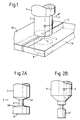
- a pair of aluminium alloy plates 1A, 1B are butted together about a joint line 2.
- a non-consumable probe 3 of steel having a narrow central, cylindrical portion 4 positioned between upper and lower sections 5,6 is brought to the edge of the joint line 2 between the plates 1A, 1B.
- the probe 3 is rotated by a motor 7 while the probe is traversed in a direction 8 and while the plates are held against lateral movement away from the probe 3.
- the rotating probe 3 produces a local region of highly plasticised material around the steel "pencil" portion 4 while top and bottom constraint is provided by the sections 5,6.
- the rotating member 3 or the bobbin can be manufactured in one piece as shown in figure 2a, with a preset gap (typically 3.3mm) between the faces 5A, 6A.
- the bobbin may be demountable and the two parts 5,6' secured, for example, by a cotter pin 9, as shown in figure 2b.
- a cotter pin 9 for example, a cotter pin 9
- the gap may be made adjustable over a short distance by a suitable cam lever or eccentric (not shown) to allow for variation in the thickness of the sheets to be joined from nominal values.
- the component parts of the bobbin may be suitably spring-loaded so that a tight fit is maintained in spite of small variation in the sheet thickness.
- a suitable run-on (and run-off) tab can be utilised.
- a split piece of similar material to that being joined can be fastened around the pin of the rotating member and pressed against the starting edge of the sheets to be joined, so that as plasticised material is formed there is minimum space for escape and a uniform zone is formed throughout the length of the seam to be joined.
- the butting faces 5A,6A of the bobbin may be machined substantially square but preferably are provided with a slight chamfer on the outer edges ( Figure 2a).
- Figure 2a In use it can be observed whether the top and bottom faces are in good contact with the materials to be joined by the visibly polished zone corresponding in width to the diameter of the faces up to the chamfer.
- the face can be slightly domed with a radius of the order of 0.1m or greater, such that a contact zone corresponding to the applied spring load is developed of sufficient width.
- the width of this contact zone should be at least 50% greater than the diameter of the pin generating plasticised material.
- the rotating member can be driven via a spline such that it floats according to the materials being joined.
- a floating head is not necessary and a preset bobbin can be used.
- FIG. 3 A joint via the above method using a two part bobbin is shown in Figure 3 for an aluminium silicon magnesium alloy (BS6082), nominally 3.2mm thick.
- the overall width of the heat affected zone is approximately 9mm wide corresponding to the contact zone on a chamfered bobbin.
- a 6mm diameter pin was rotated at 1500rpm (peripheral speed of approximately 0.47m/sec) and traversed along the joint line at 370mm per minute.
- the contact faces of the bobbin contribute to the heat input as well as the heating provided by the rotating pin and corresponding plasticised zone.
- the travel rate is also reduced, such as at 800rpm, a suitable travel speed is 190mm per minute. Excess travel speed leads to void formation or lack of consolidation of the plasticised material.
- the plasticised material is swept around the rotating probe 4 such that voids, if any, tend to form on the side where the rotating surface is moving in the same direction as the travel along the joint (advancing edge). It appears there is no difficulty in obtaining complete consolidation with the plasticised material filling the joint zone in other regions, particularly on the side where the rotating surface is against the direction of travel of the bobbin through the material (retreating edge).
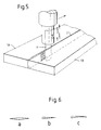
- Figure 5 shows a further method according to the invention by which the heating is obtained from a reciprocating blade 11 about which plasticised material is formed, and which is passed along the joint line 2.
- the blade 11 can be reciprocated from one side only or between two synchronized heads on either side of the materials.
- the sheets 1A,1B are placed in contact but generally without an abutment load prior to traversing the blade 11 along the joint line. If necessary guard plates can be mounted above and below the materials to be joined to prevent excessive displacement of plasticised material out of the joint zone.
- a degree of pre-heating the blade 11, eg., by passing an electric current down the length of the blade can add to the heating due to rapid mechanical shear in the plasticised zone.
- the reciprocating blade 11 can in principle be used, it is preferable for the reciprocating blade to be shaped in cross section and in particular to have a relatively narrow wedge shaped trailing edge.
- a double wedge profile is shown in Fig. 6a where the overall length in the direction of travel is preferably between 5 and 15 times the width.
- the width should be as small as convenient, such as around 1mm, and the blade made of material which is sufficiently strong at the melting point temperatures of the thermoplastic, ie., at temperatures between 250 and 300°C to withstand the mechanical forces and in particular to not buckle.
- tool steel or other hard steel can be ground into the shape desired and the surface polished to give a fine finish.
- the blade can pass through guard plates to prevent excessive plasticised material being taken out of the joint zone, and these guard plates may also be made of tool steel and lined with a low frictional resistance material such as PTFE.
- the double wedge shape is particularly useful for moving in either direction along the common joint line.
- a single ended wedge is shown in Fig. 6b where preferably the overall length is between 3 and 10 times the width and the leading edge is rounded. This shape is used with the rounded end in the direction of travel along a straight joint line and can also be used for joining along a curved line of relatively large radius.
- a further arrangement for curved joints is shown in Figure 6c, where the trailing edge is curved in section to correspond approximately with the curvature of the joint line.
- the displacement is preferably equal to or less than half the overall thickness of the material being joined, ie., ⁇ 3mm or less for 6mm sheet and so forth. Greater strokes lead to excessive loss of material from the joint and consequent voids or porosity. It is noted that the plasticised material tends to cling to the blade and is pulled and pushed with reciprocating motion in the through thickness direction. Operating conditions are chosen such that the build up of plasticised material on the blade is avoided or minimised.
- the frequency of reciprocating motion depends partly on the amplitude, and partly on the material being joined.
- the maximum (sinusoidal) velocity in the mid stroke position is in the region of 0.5m/sec to 5 m/sec.
- the preferred velocities are in the range of 0.75 metre per second to 4.5 metres per second. The higher velocities lead to greater heating and in the limit to degradation of the thermoplastic material.
- the reciprocating blade 11 can be preheated prior to the frictional operation. Any convenient method can be used ie., Joule heating of the blade, or heating by hot gases, or maintaining the blade in a preheated sheath prior to use. Where advantageous the blade may also be electrically heated in use as well as developing thermal energy through mechanical work.
- FIG. 7 A typical joint in an amorphous thermoplastic material - white polyethylene - is shown in Fig. 7 for 6mm thick material.
- the blade stroke was approximately ⁇ 3mm at around 47Hz giving a maximum sinusoidal mid stroke speed of 0.88 metre per second.
- the butt joint is completed at a rate of 30mm per minute giving an overall joint completion rate (depth and length per unit time) of 3mm2 per second. It should be noted that this greatly exceeds that possible with the hot gas welding technique which is commonly used, and which for this thickness would require several passes.
- a simple tensile test across the butt joint as-welded shows a strength well in excess of 50% of the parent material alone.
- the joint is virtually free from pores or flat spot areas and provides a narrow bead on the top and bottom surfaces of the butt joint.
- the bead profile does not exhibit the central re-entrant angle commonly found in thermoplastic materials joined by the hot butt techniques.
- FIG. 8 A typical butt joint in a semi-crystalline material - clear PVC - is shown in Fig. 8 for 6mm thick sheet joined under similar conditions to that for the polyethylene material with a travel rate of 30mm per minute. Again a simple tensile test shows strength above 50% of parent material alone with a good profile with top and bottom beads.
- the section Fig. 8 shows the flow lines of the heat affected material, as well as the zone where the plasticised material has formed the joint. Higher travel speeds can be used but speeds in excess of 90mm per minute lead to the occurrence of voids or other porosity in the joint.
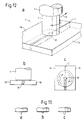
- FIG. 10 Various examples of different joints in thermoplastic material using a reciprocating blade is shown in Fig. 10.
- a simple seal between overlapping sheets is shown in Fig. 10a, the solid line 12 indicating the line along which the probe or blade extends.
- This method may also be adapted as sketched in Fig. 10b and c, for the joining of two sheets of similar thickness.
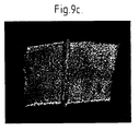
- Fig. 9a shows a real joint similar to Figure 10a between two sheets of clear PVC 6mm thick with the same operating conditions as for Fig. 7 of stroke ⁇ 3mm and frequency around 47Hz. The travel rate used was still 30mm per minute in spite of the double thickness 12mm total.
- FIG. 10e Another arrangement suitable for the joining or sealing is shown in Fig. 10e where two 3mm sheets are joined to one 6mm thick sheet in a butt configuration.
- a clear plastic such as clear PVC enables the joint to be inspected for quality.
- This is shown in macrosection in Figure 9b.
- a further joint is shown in Fig. 10d where for thick plate the ends have been upset to give an extended joint area.
- the stroke may be for example ⁇ 13mm at a frequency of around 53Hz giving a maximum velocity of around 4.3 metres per second. With a travel speed of 40mm per minute the overall joining rate is around 20mm2 per second of butting section.
- Fig. 10f shows a joint between fibre reinforced polyethylene with a 20% by weight inclusion of short glass fibres. Conditions similar to those used for Fig. 7 were employed with 30mm per minute travel rate for material 6.5mm thick. A joint strength in the order of 50% of the parent material or about 80% of the plain un-reinforced polyethylene was obtained.
- FIG. 11 An alternative approach to increase the effective joint strength is shown in Fig. 11 where with the same reciprocating blade 11 a scarf joint is made between two abutting sheets 13,14 having sloped edges 13A,14A defining a joint region 15. This arrangement also allows the two sheets 13,14 to be held in position via rollers 16,17 and any tendency to pull apart restrained.
- a hand tool similar to a conventional jig saw for achieving the joint between butting or overlapping plastic materials.
- a relatively thin blade of small longitudinal dimension such as 1mm x 4mm of the general shape shown in Fig. 6c is desirable.
- Such hand tools can also be fitted with caterpillar type crawler tracks to maintain a uniform forward velocity.
- the tracks may be made with rubber impregnated track faces or partially evacuated to improve traction and adherence to the surface of the plastic material.
- the non-consumable member has a slightly tapered cylindrical probe 18 at its leading end, which is pressed against and becomes inserted between the plates 1A,1B, but does not extend completely through the thickness of the materials being joined as shown in Figure 12b.
- the surface appearance of the plates after the butt welding operation is shown in Figure 12c for the upper surface.
- the shape of the probe is important.
- a simple conical point ( Figure 13a) enables the probe to enter the plates butted together relatively easily but results in a narrowing of the plasticised region near the apex of the probe.
- a truncated cone such as shown in Figure 13b, requires preferably a pre-drilled depression in the butting sheets to be joined.
- the probe is of a slightly tapered cylindrical form with a blunt nose, as shown in Figure 13c. This enables the probe to be pressed against the sheets so that it becomes inserted forming a plasticised zone around the probe which travels along the joint seam as previously described.
- the probe may be rotated at 850rpm and traversed along the joint line at 240mm per minute.
- Higher rotational speeds such as 1000rpm, enable greater travel rates to be used up to say 300mm per second, but increasing the travel rate excessively leads to the formation of pores along one side as was found with the parallel sided arrangement of Figure 1.
- the rotational speed can be reduced such as down to 300rpm with a corresponding reduction in travel rate.
- there is a reasonable tolerance in rotational rates such as at 4mm per second (240mm per minute) for the aluminium silicon magnesium alloy (BS6082) satisfactory results are obtained for rotational speeds between 440 and 850rpm.
- the method described with respect to Figures 1, 5 and 12 can be applied to the joining together of the abutting faces of a crack in a given material or component.
- the crack may be in the full thickness, or only partially penetrating the thickness, and may lie in parent material, or a heat affected zone in the material, such as adjacent to a weld or in a weld itself.
- the method of Figure 12 is generally suitable for a partially penetrating crack, although in principle a fully penetrating method such as that shown in Figure 5 could also be utilised.
- the technique is essentially similar to that already described, where preferably the probe is inserted into the parent material (to the depth of the crack at least) before passing along the crack interface, to generate plasticised material by frictional heating which on cooling consolidates the material where the crack previously existed.
- the end of the crack in the direction of travel can be consolidated in various ways.
- the probe can be left in-situ or, alternatively, a pass made in the reverse direction and overlapped with the initial pass so that the termination of the reverse pass lies in a region away from the original crack site.
- a similar technique for making a local joint or weld but without traversing the tool for generating frictional heating can be utilised for a probe applied to one-side of the material.
- the plasticised material formed is utilised to stitch together two components at discrete intervals along their common interface.
- a crack can be held together by local plasticised material at one or more regions along its length.
- plasticised material is generated by frictional shear from a separate component inserted into the parent material and which on cooling consolidates the material or surrounds the component to restrain it in the material is within the scope of this invention.
- the result of the welding operation is an extremely smooth finish on the surfaces of the plates which is a particular advantage of this process.
- This can be improved by providing Ferodo brake material on the facing surface of the non-consumable probe.
- the rotational speed of the non-consumable will be between 300 and 600 rpm and the traverse rate of the workpiece is in the range of 1 to 6mm/sec.
- the non-consumable will be made of an alloy steel.
- Non-consumable technique Continuous - unlimited length
- No preparation Reasonable smooth finish Good mechanical properties Solid phase
- Low distortion Limited axial load ie. no axial feed only light contact
- Portable equipment KAT driven Joint can be produced from one side Simple to use Low cost capital equipment Fast freeze 5G position
- applications of the technique include: Autogenous key hole technique, Plate fabrication in ship building, Pipe butt welding, Aluminium Armour plate, Pipe seam, Fracture repair, Plastic welding, and fabrication of joists etc.
Abstract
Description
- The invention relates to friction welding for joining two workpieces or two sides of a workpiece.
- Friction welding has been known for many years and typically involves causing relative movement between a pair of workpieces while they are urged together so as to generate a plasticised region, stopping the relative movement and allowing the plasticised region to solidify thereby joining the workpieces.
- It has also been proposed in the past to join workpieces by making use of a "non-consumable" member which does not form part of the finished joint. An example of this approach is shown in US-A-4144110 in which the two workpieces are urged together about a rotating wheel which causes the plasticised region to be generated. The two workpieces are also translated relative to the wheel so that they are welded together along a joint region. Similar techniques for welding straight-seamed metal pipes are disclosed in SU-A-1433522 and SU-A-1362593. The problem in all these cases is that the zone which is heated is displaced from the point at which the workpieces or sides of the pipe are urged together with the result that such techniques would need to be carried out in carefully controlled atmospheres to prevent oxidation of the plasticised region in for example aluminium.
- JP-A-61176484 discloses a technique using "consumable" spinning plugs which are positioned between opposed faces of the workpieces and cause the generation of plasticised regions within the workpieces and within themselves so that as the workpieces are urged together the spinning plugs are accumulated into the plasticised region and thereby form part of the resulting joint. This is a complex procedure requiring the ability to rotate a multitude of spinning plugs and to ensure that the plug material is compatible with the material of the workpieces. A similar approach is described in JP-A-57-149082.
- In accordance with the present invention, a method of joining workpieces defining a joint region therebetween comprises carrying out the following steps without causing relative bodily movement between the workpieces: causing a probe of material harder than the workpiece material to enter the joint region and opposed portions of the workpieces on either side of the joint region while causing relative cyclic movement between the probe and the workpieces whereby frictional heat is generated to cause the opposed portions to take up a plasticised condition; removing the probe; and allowing the plasticised portions to solidify and join the workpieces together.
- This technique, which we refer to as "friction stir butt welding" enables a wide variety of workpieces to be joined using a "non-consumable" probe. This technique can be used to join workpieces or the opposed sides of a workpiece in for example pipes and cracked materials and the like. The problems of the prior art mentioned above are overcome. In particular, the workpieces will not normally be urged towards each other but simply restrained against movement away from the joint region during passage of the probe. The probe plasticises the portions of the workpieces immediately adjacent the probe so that upon removal or translation of the probe these regions will immediately coalesce and solidify. The problems of oxidation and the like are thereby avoided.
- This method can be used to join workpieces along a common plane, as in butt joints by heating and disrupting a local zone formed between the components such that on cooling a common bond is established as the local active zone is translated along the joint. In particular the method generally results in a mix of the two abutting surfaces, often at temperatures below the true melting point of the materials to be joined.
- The materials can be metals, alloys or compound materials such as MMC, or suitable plastic materials such as thermo-plastics.
- In some cases, the workpieces are joined at spaced locations along the joint region, the probe being withdrawn from one point, traversed to the next point and then reinserted between the workpieces. Preferably, when the joint region has an elongate dimension extending laterally between the workpieces, the method further comprises causing relative translational movement between the workpieces and the probe in the direction of the joint region.
- In one example of the method a substantially non-consumable probe is inserted between the materials to be joined in say a butt joint configuration and rotated to produce frictional heating. With sufficient heating a layer of plasticised material is formed around the probe generally composed of both materials to be joined, such that on slowly traversing the rotating probe along the joint line, the plasticised material is spread along the joint. On cooling, the plasticised material bonds the components together as desired.
- In some examples, the probe has an elongate axis and undergoes cyclic movement, for example a reciprocating movement, in a direction generally parallel with its elongate axis. The probe can then be moved to allow the workpieces to be joined together.
- In all these methods, the probe may have a substantially circular cross-section.
- In another example the probe is in the form of a slightly tapering cylinder so that it may be inserted from one side of the joint, forming a plasticised layer to the depth of penetration of the probe.
- In yet another example, a probe blade is reciprocated in the through thickness direction to produce heating of the joint such that on traversing along the joint line the plasticised material passes around the blade and on cooling consolidates the joint.
- Preferably the plasticised material is restrained from extruding from the joint region, for example by a suitable cap or shoe which closely fits the workpiece surface. In a further example of the probe method, the probe may be heated prior to frictioning by other means such as electric resistance (Joule) heating. In the latter case the probe may conveniently take the form of a thin blade or knife which is pressed into the joint line forming heated or plasticised material from the material of the components to be joined by frictioning as described above. This again on cooling bonds the components along their common joint line.
- One advantage of the method according to the invention is that the depth of operation, and hence the depth of suitably heated or plasticised material is accurately controlled and known in advance.
- Another advantage is that the butting surfaces are directly acted on by the probe, and that bond defects (flat spots) on the joint faces are inherently minimised or prevented.
- A further advantage of the method according to the invention is that a given tool can be utilised for long seams without limit, and that relatively deep joints can be made in one pass.
- Some examples of methods according to the invention will now be described with reference to the accompanying drawings, in which:-
- Figure 1 is an isometric view illustrating one method;
- Figures 2a and 2b are side elevations of two different rotating members;
- Figure 3 is a macro-section through a joint in aluminium alloy using the method of figure 1;
- Figure 4 is a plan illustrating the flow of plasticised material and surface marking with respect to the joint line;
- Figure 5 is an isometric view illustrating a second method;
- Figures 6a, b & c are examples of blades used in reciprocating motion;
- Figure 7 is a cross section (X7.5) through a butt joint in 6mm thick amorphous thermoplastic material made using the method of Figure 5;
- Figure 8 is a cross section through a butt joint in 6mm thick semi-crystalline thermoplastic material using the method of Figure 5;
- Figures 9a-9c are macro-sections showing a 12mm thick overlapped (i.e. two 6mm thick sheets) amorphous thermoplastic material, a reciprocating motion multiple butt joint in amorphous thermoplastic material, and a reciprocating motion butt joint in 6.6mm glass fibre reinforced material respectively;
- Figures 10a, b,c,d,e & f are various sections showing three arrangements of an overlap joint, a butt joint in thick PVC, a multiple butt joint with at least one transparent thermoplastic material and a butt joint in a glass fibre reinforced thermoplastic material respectively using the method of Figure 5;
- Figure 11 is an isometric view of a variation of the method of Figure 5 for making a scarf joint;
- Figures 12, a,b & c are an isometric view, end view and plan respectively of a third example;
- Figures 13a, b, and c show various examples of probe shape for use with the method of Figure 12; and,
- Figures 14a and 14b are a schematic view of a further process and a macro-section (x4) of an arrangement with two passes above and below the plates.
- In the example shown in Figure 1, a pair of
aluminium alloy plates joint line 2. Anon-consumable probe 3 of steel having a narrow central, cylindrical portion 4 positioned between upper andlower sections joint line 2 between theplates probe 3 is rotated by amotor 7 while the probe is traversed in adirection 8 and while the plates are held against lateral movement away from theprobe 3. The rotatingprobe 3 produces a local region of highly plasticised material around the steel "pencil" portion 4 while top and bottom constraint is provided by thesections - It should be noted that the constraining faces of the
sections sheets member 3 or the bobbin can be manufactured in one piece as shown in figure 2a, with a preset gap (typically 3.3mm) between thefaces 5A, 6A. - Alternatively, the bobbin may be demountable and the two
parts 5,6' secured, for example, by acotter pin 9, as shown in figure 2b. For this it is convenient to drill a hole corresponding to the pin diameter in the butting sheets to be joined and the twoparts 5,6' of the bobbin brought together firmly onto the sheets before securing. Furthermore, the gap may be made adjustable over a short distance by a suitable cam lever or eccentric (not shown) to allow for variation in the thickness of the sheets to be joined from nominal values. Yet again, the component parts of the bobbin may be suitably spring-loaded so that a tight fit is maintained in spite of small variation in the sheet thickness. In all cases to avoid pre-drilling a suitable hole in the butting sheets to be joined, a suitable run-on (and run-off) tab can be utilised. For example, a split piece of similar material to that being joined can be fastened around the pin of the rotating member and pressed against the starting edge of the sheets to be joined, so that as plasticised material is formed there is minimum space for escape and a uniform zone is formed throughout the length of the seam to be joined. - The butting faces 5A,6A of the bobbin may be machined substantially square but preferably are provided with a slight chamfer on the outer edges (Figure 2a). In use it can be observed whether the top and bottom faces are in good contact with the materials to be joined by the visibly polished zone corresponding in width to the diameter of the faces up to the chamfer. Alternatively, and particularly for the spring loaded version, the face can be slightly domed with a radius of the order of 0.1m or greater, such that a contact zone corresponding to the applied spring load is developed of sufficient width. Preferably the width of this contact zone should be at least 50% greater than the diameter of the pin generating plasticised material.
- With suitable bobbins as described the rotating member can be driven via a spline such that it floats according to the materials being joined. With pre-machined components in a suitable jig then a floating head is not necessary and a preset bobbin can be used.
- A joint via the above method using a two part bobbin is shown in Figure 3 for an aluminium silicon magnesium alloy (BS6082), nominally 3.2mm thick. The overall width of the heat affected zone is approximately 9mm wide corresponding to the contact zone on a chamfered bobbin. For this a 6mm diameter pin was rotated at 1500rpm (peripheral speed of approximately 0.47m/sec) and traversed along the joint line at 370mm per minute. It should be noted that the contact faces of the bobbin contribute to the heat input as well as the heating provided by the rotating pin and corresponding plasticised zone. For lower rotational rates the travel rate is also reduced, such as at 800rpm, a suitable travel speed is 190mm per minute. Excess travel speed leads to void formation or lack of consolidation of the plasticised material.
- As illustrated in figure 4, the plasticised material is swept around the rotating probe 4 such that voids, if any, tend to form on the side where the rotating surface is moving in the same direction as the travel along the joint (advancing edge). It appears there is no difficulty in obtaining complete consolidation with the plasticised material filling the joint zone in other regions, particularly on the side where the rotating surface is against the direction of travel of the bobbin through the material (retreating edge).
- Figure 5 shows a further method according to the invention by which the heating is obtained from a
reciprocating blade 11 about which plasticised material is formed, and which is passed along thejoint line 2. As previously the mechanical motion generates frictional heat in the plasticised material which, with traverse, flows from the beading to the trailing edges of theblade 11 and on cooling completes the butt joint between the materials to be joined. Theblade 11 can be reciprocated from one side only or between two synchronized heads on either side of the materials. For making the butt joint, thesheets blade 11 along the joint line. If necessary guard plates can be mounted above and below the materials to be joined to prevent excessive displacement of plasticised material out of the joint zone. Also for some materials a degree of pre-heating theblade 11, eg., by passing an electric current down the length of the blade can add to the heating due to rapid mechanical shear in the plasticised zone. - Although a simple thin
rectangular blade 11 can in principle be used, it is preferable for the reciprocating blade to be shaped in cross section and in particular to have a relatively narrow wedge shaped trailing edge. A double wedge profile is shown in Fig. 6a where the overall length in the direction of travel is preferably between 5 and 15 times the width. The width should be as small as convenient, such as around 1mm, and the blade made of material which is sufficiently strong at the melting point temperatures of the thermoplastic, ie., at temperatures between 250 and 300°C to withstand the mechanical forces and in particular to not buckle. For example, tool steel or other hard steel can be ground into the shape desired and the surface polished to give a fine finish. Where desirable, the blade can pass through guard plates to prevent excessive plasticised material being taken out of the joint zone, and these guard plates may also be made of tool steel and lined with a low frictional resistance material such as PTFE. The double wedge shape is particularly useful for moving in either direction along the common joint line. - A single ended wedge is shown in Fig. 6b where preferably the overall length is between 3 and 10 times the width and the leading edge is rounded. This shape is used with the rounded end in the direction of travel along a straight joint line and can also be used for joining along a curved line of relatively large radius. A further arrangement for curved joints is shown in Figure 6c, where the trailing edge is curved in section to correspond approximately with the curvature of the joint line.
- For the reciprocating blades the displacement is preferably equal to or less than half the overall thickness of the material being joined, ie., ± 3mm or less for 6mm sheet and so forth. Greater strokes lead to excessive loss of material from the joint and consequent voids or porosity. It is noted that the plasticised material tends to cling to the blade and is pulled and pushed with reciprocating motion in the through thickness direction. Operating conditions are chosen such that the build up of plasticised material on the blade is avoided or minimised.
- The frequency of reciprocating motion depends partly on the amplitude, and partly on the material being joined. Preferably the maximum (sinusoidal) velocity in the mid stroke position is in the region of 0.5m/sec to 5 m/sec. For materials such as polyethylene and PVC the preferred velocities are in the range of 0.75 metre per second to 4.5 metres per second. The higher velocities lead to greater heating and in the limit to degradation of the thermoplastic material.
- To assist in initiation of the seam the
reciprocating blade 11 can be preheated prior to the frictional operation. Any convenient method can be used ie., Joule heating of the blade, or heating by hot gases, or maintaining the blade in a preheated sheath prior to use. Where advantageous the blade may also be electrically heated in use as well as developing thermal energy through mechanical work. - A typical joint in an amorphous thermoplastic material - white polyethylene - is shown in Fig. 7 for 6mm thick material. For this the blade stroke was approximately ± 3mm at around 47Hz giving a maximum sinusoidal mid stroke speed of 0.88 metre per second. The butt joint is completed at a rate of 30mm per minute giving an overall joint completion rate (depth and length per unit time) of 3mm² per second. It should be noted that this greatly exceeds that possible with the hot gas welding technique which is commonly used, and which for this thickness would require several passes. A simple tensile test across the butt joint as-welded shows a strength well in excess of 50% of the parent material alone. It is also noted that the joint is virtually free from pores or flat spot areas and provides a narrow bead on the top and bottom surfaces of the butt joint. The bead profile does not exhibit the central re-entrant angle commonly found in thermoplastic materials joined by the hot butt techniques.
- A typical butt joint in a semi-crystalline material - clear PVC - is shown in Fig. 8 for 6mm thick sheet joined under similar conditions to that for the polyethylene material with a travel rate of 30mm per minute. Again a simple tensile test shows strength above 50% of parent material alone with a good profile with top and bottom beads. The section Fig. 8 shows the flow lines of the heat affected material, as well as the zone where the plasticised material has formed the joint. Higher travel speeds can be used but speeds in excess of 90mm per minute lead to the occurrence of voids or other porosity in the joint.
- Various examples of different joints in thermoplastic material using a reciprocating blade is shown in Fig. 10. A simple seal between overlapping sheets is shown in Fig. 10a, the
solid line 12 indicating the line along which the probe or blade extends. This method may also be adapted as sketched in Fig. 10b and c, for the joining of two sheets of similar thickness. Fig. 9a shows a real joint similar to Figure 10a between two sheets of clear PVC 6mm thick with the same operating conditions as for Fig. 7 of stroke ± 3mm and frequency around 47Hz. The travel rate used was still 30mm per minute in spite of the double thickness 12mm total. - Another arrangement suitable for the joining or sealing is shown in Fig. 10e where two 3mm sheets are joined to one 6mm thick sheet in a butt configuration. A clear plastic such as clear PVC enables the joint to be inspected for quality. This is shown in macrosection in Figure 9b. A further joint is shown in Fig. 10d where for thick plate the ends have been upset to give an extended joint area. For this the stroke may be for example ± 13mm at a frequency of around 53Hz giving a maximum velocity of around 4.3 metres per second. With a travel speed of 40mm per minute the overall joining rate is around 20mm² per second of butting section.
- Finally, Fig. 10f (and Figure 9c) shows a joint between fibre reinforced polyethylene with a 20% by weight inclusion of short glass fibres. Conditions similar to those used for Fig. 7 were employed with 30mm per minute travel rate for material 6.5mm thick. A joint strength in the order of 50% of the parent material or about 80% of the plain un-reinforced polyethylene was obtained.
- It should be noted that these nominal tensile strengths are for as-welded specimens and that with further combinations of parameters to provide an optimum result strengths approaching that of a parent material should be obtainable.
- An alternative approach to increase the effective joint strength is shown in Fig. 11 where with the same reciprocating blade 11 a scarf joint is made between two abutting
sheets edges joint region 15. This arrangement also allows the twosheets rollers - It should be noted that the end load in the direction of travel of the
reciprocating blade 11 under suitable joining conditions is relatively low and only a simple traverse mechanism is required to maintain uniform motion. - Alternatively and particularly for thin sheet below, 10mm, it is possible to use a hand tool similar to a conventional jig saw for achieving the joint between butting or overlapping plastic materials. For curved joint lines a relatively thin blade of small longitudinal dimension such as 1mm x 4mm of the general shape shown in Fig. 6c is desirable. Such hand tools can also be fitted with caterpillar type crawler tracks to maintain a uniform forward velocity. The tracks may be made with rubber impregnated track faces or partially evacuated to improve traction and adherence to the surface of the plastic material.
- In the example of Figure 12 the non-consumable member has a slightly tapered
cylindrical probe 18 at its leading end, which is pressed against and becomes inserted between theplates - The shape of the probe is important. A simple conical point (Figure 13a) enables the probe to enter the plates butted together relatively easily but results in a narrowing of the plasticised region near the apex of the probe. Alternatively, a truncated cone, such as shown in Figure 13b, requires preferably a pre-drilled depression in the butting sheets to be joined. Preferably the probe is of a slightly tapered cylindrical form with a blunt nose, as shown in Figure 13c. This enables the probe to be pressed against the sheets so that it becomes inserted forming a plasticised zone around the probe which travels along the joint seam as previously described.
- For a joint between aluminium alloy plates 6mm thick made by the method illustrated in Figure 12, the probe may be rotated at 850rpm and traversed along the joint line at 240mm per minute. Higher rotational speeds, such as 1000rpm, enable greater travel rates to be used up to say 300mm per second, but increasing the travel rate excessively leads to the formation of pores along one side as was found with the parallel sided arrangement of Figure 1. Alternatively, the rotational speed can be reduced such as down to 300rpm with a corresponding reduction in travel rate. For a given travel speed there is a reasonable tolerance in rotational rates such as at 4mm per second (240mm per minute) for the aluminium silicon magnesium alloy (BS6082) satisfactory results are obtained for rotational speeds between 440 and 850rpm.
- The method described with respect to Figures 1, 5 and 12 can be applied to the joining together of the abutting faces of a crack in a given material or component. The crack may be in the full thickness, or only partially penetrating the thickness, and may lie in parent material, or a heat affected zone in the material, such as adjacent to a weld or in a weld itself. The method of Figure 12 is generally suitable for a partially penetrating crack, although in principle a fully penetrating method such as that shown in Figure 5 could also be utilised. The technique is essentially similar to that already described, where preferably the probe is inserted into the parent material (to the depth of the crack at least) before passing along the crack interface, to generate plasticised material by frictional heating which on cooling consolidates the material where the crack previously existed. The end of the crack in the direction of travel can be consolidated in various ways. For example the probe can be left in-situ or, alternatively, a pass made in the reverse direction and overlapped with the initial pass so that the termination of the reverse pass lies in a region away from the original crack site.
- A similar technique for making a local joint or weld but without traversing the tool for generating frictional heating can be utilised for a probe applied to one-side of the material. Here for example the plasticised material formed is utilised to stitch together two components at discrete intervals along their common interface. In like manner a crack can be held together by local plasticised material at one or more regions along its length.
- These and other variations of the method according to the invention in which plasticised material is generated by frictional shear from a separate component inserted into the parent material and which on cooling consolidates the material or surrounds the component to restrain it in the material is within the scope of this invention.
- In all these examples, the result of the welding operation is an extremely smooth finish on the surfaces of the plates which is a particular advantage of this process. This can be improved by providing Ferodo brake material on the facing surface of the non-consumable probe. Typically the rotational speed of the non-consumable will be between 300 and 600 rpm and the traverse rate of the workpiece is in the range of 1 to 6mm/sec. Typically, the non-consumable will be made of an alloy steel.
- Specimens have been produced and subjected to mechanical tensile and hammer bend tests as well as metallurgical evaluation which have demonstrated the practicability of the process.
- The advantages of the process can be summarised as follows:
Non-consumable technique
Continuous - unlimited length
No preparation
Reasonable smooth finish
Good mechanical properties
Solid phase,
Low distortion
Limited axial load ie. no axial feed only light contact
Key hole technique
Portable equipment KAT driven
Joint can be produced from one side
Simple to use
Low cost capital equipment
Fast freeze 5G position
Examples of applications of the technique include:
Autogenous key hole technique, Plate fabrication in ship building, Pipe butt welding, Aluminium Armour plate, Pipe seam, Fracture repair, Plastic welding, and fabrication of joists etc.
Claims (9)
- A method of joining workpieces (1A,1B) defining a joint region (2) therebetween, the method comprising carrying out the following steps without causing relative bodily movement between the workpieces: causing a probe (3) of material harder than the workpiece material to enter the joint region (2) and opposed portions of the workpieces on either side of the joint region while causing relative cyclic movement between the probe and the workpieces whereby frictional heat is generated to cause the opposed portions to take up a plasticised condition; removing the probe (3); and allowing the plasticised portions to solidify and join the workpieces together.
- A method according to claim 1, wherein the joint region (2) has an elongate dimension extending laterally between the workpieces, the method further comprising causing relative translational movement between the workpieces and the probe in the direction of the joint region.
- A method according to claim 1 or claim 2, wherein the probe (3) extends through the thickness of the workpieces (1A,1B).
- A method according to any of claims 1 to 3, wherein the probe (3) has an elongate axis which substantially intersects the joint region and extends substantially parallel with the sides of the workpiece defining the joint region.
- A method according to any of claims 1 to 3, wherein the probe defines an elongate axis which extends in a direction substantially transverse to a plane parallel with the joint region.
- A method according to any of claims 1 to 5, wherein the workpieces comprise separate members.
- A method according to any of the preceding claims, wherein the probe has an elongate axis and undergoes cyclic movement in a direction generally parallel with its elongate axis.
- A method according to claim 7, wherein the cyclic movement is a reciprocating movement.
- A method according to any of the preceding claims, wherein a cross-section through the probe is substantially circular.
Priority Applications (1)
| Application Number | Priority Date | Filing Date | Title |
|---|---|---|---|
| EP19940120385 EP0653265A3 (en) | 1991-12-06 | 1992-11-27 | Improvements relating to friction welding. |
Applications Claiming Priority (3)
| Application Number | Priority Date | Filing Date | Title |
|---|---|---|---|
| GB9125978 | 1991-12-06 | ||
| GB9125978A GB9125978D0 (en) | 1991-12-06 | 1991-12-06 | Hot shear butt welding |
| PCT/GB1992/002203 WO1993010935A1 (en) | 1991-12-06 | 1992-11-27 | Improvements relating to friction welding |
Related Child Applications (1)
| Application Number | Title | Priority Date | Filing Date |
|---|---|---|---|
| EP94120385.3 Division-Into | 1994-12-22 |
Publications (2)
| Publication Number | Publication Date |
|---|---|
| EP0615480A1 EP0615480A1 (en) | 1994-09-21 |
| EP0615480B1 true EP0615480B1 (en) | 1995-11-08 |
Family
ID=10705824
Family Applications (2)
| Application Number | Title | Priority Date | Filing Date |
|---|---|---|---|
| EP19940120385 Withdrawn EP0653265A3 (en) | 1991-12-06 | 1992-11-27 | Improvements relating to friction welding. |
| EP92923936A Expired - Lifetime EP0615480B1 (en) | 1991-12-06 | 1992-11-27 | Improvements relating to friction welding |
Family Applications Before (1)
| Application Number | Title | Priority Date | Filing Date |
|---|---|---|---|
| EP19940120385 Withdrawn EP0653265A3 (en) | 1991-12-06 | 1992-11-27 | Improvements relating to friction welding. |
Country Status (9)
| Country | Link |
|---|---|
| US (1) | US5460317B1 (en) |
| EP (2) | EP0653265A3 (en) |
| JP (1) | JP2712838B2 (en) |
| AU (2) | AU658950B2 (en) |
| CA (1) | CA2123097C (en) |
| DE (1) | DE69205991T2 (en) |
| GB (1) | GB9125978D0 (en) |
| HK (1) | HK1006431A1 (en) |
| WO (1) | WO1993010935A1 (en) |
Cited By (17)
| Publication number | Priority date | Publication date | Assignee | Title |
|---|---|---|---|---|
| DE19957136C1 (en) * | 1999-11-18 | 2001-02-08 | Geesthacht Gkss Forschung | Friction welding appts has a projecting and rotating pin to act on the workpiece materials at the welding zone to follow the welding line and soften the materials to fuse together and bond sheet plates with complex shapes |
| DE19955737A1 (en) * | 1999-11-18 | 2001-06-13 | Geesthacht Gkss Forschung | Method and device for connecting at least two adjacent workpieces according to the method of friction stir welding |
| US6328261B1 (en) * | 1997-06-20 | 2001-12-11 | Bae Systems Plc | Friction welding metal components |
| DE10063920A1 (en) * | 2000-12-20 | 2002-09-12 | Thyssenkrupp Stahl Ag | Method for joining two workpieces from a material which can be plasticized by heating, in particular metal, in particular in the form of metal sheets, in the butt joint |
| EP1442824A2 (en) | 1997-07-23 | 2004-08-04 | Hitachi, Ltd. | Friction stir welding method, frame members used therein, and product formed thereby |
| US6789722B2 (en) | 2001-03-29 | 2004-09-14 | Mazda Motor Corporation | Joining method and apparatus using frictional agitation |
| DE102004028560B3 (en) * | 2004-06-15 | 2005-11-03 | Gkss-Forschungszentrum Geesthacht Gmbh | Device for joining workpieces by the method of friction stir welding |
| DE102004028553B3 (en) * | 2004-06-15 | 2005-11-03 | Gkss-Forschungszentrum Geesthacht Gmbh | Device for joining workpieces by the method of friction stir welding |
| DE102008054449A1 (en) | 2007-12-19 | 2009-06-25 | Alstom Technology Ltd. | Method for connecting two conductor pieces |
| EP2106891A1 (en) | 2008-04-04 | 2009-10-07 | komax Holding AG | Hotplate for workpieces |
| US7740162B2 (en) | 2002-11-01 | 2010-06-22 | Airbus UK, Limited | Welding method |
| US8020748B2 (en) | 2006-09-12 | 2011-09-20 | Toso SMD, Inc. | Sputtering target assembly and method of making same |
| WO2013076472A1 (en) | 2011-11-24 | 2013-05-30 | The Welding Institute | Friction stir welding tool with two contacting shoulders |
| DE102014225966A1 (en) | 2014-12-16 | 2016-06-16 | Continental Automotive Gmbh | Impeller housing with a bypass valve device for exhaust gas turbocharger and turbocharger |
| DE102014226214A1 (en) | 2014-12-17 | 2016-06-23 | Continental Automotive Gmbh | Compressor impeller with threaded bushing for an exhaust gas turbocharger, turbocharger rotor and turbocharger |
| DE102015216319A1 (en) | 2015-08-26 | 2017-03-02 | Continental Automotive Gmbh | Turbocharger rotor for an exhaust gas turbocharger and turbocharger |
| US10677257B2 (en) | 2016-03-25 | 2020-06-09 | Garrett Transportation I Inc. | Turbocharger compressor wheel assembly |
Families Citing this family (395)
| Publication number | Priority date | Publication date | Assignee | Title |
|---|---|---|---|---|
| GB9310469D0 (en) * | 1993-05-20 | 1993-07-07 | Welding Inst | Friction joining |
| NO942790D0 (en) * | 1994-03-28 | 1994-07-27 | Norsk Hydro As | Method of friction welding and device for the same |
| AU4904896A (en) * | 1995-01-27 | 1996-08-14 | Andersen Corporation | Vibratory welded window and door joints, method and apparatus for manufacturing the same |
| GB9510859D0 (en) * | 1995-05-30 | 1995-07-26 | Welding Inst | Improvements relating to friction welding |
| GB2306366A (en) * | 1995-10-20 | 1997-05-07 | Welding Inst | Friction stir welding |
| NO954273D0 (en) * | 1995-10-26 | 1995-10-26 | Norsk Hydro As | Wheels Wheel |
| US5611479A (en) * | 1996-02-20 | 1997-03-18 | Rockwell International Corporation | Friction stir welding total penetration technique |
| CN1322242C (en) * | 1996-03-19 | 2007-06-20 | 株式会社日立制作所 | Friction welding method and structure body formed by friction welding method |
| US5725698A (en) * | 1996-04-15 | 1998-03-10 | Boeing North American, Inc. | Friction boring process for aluminum alloys |
| DE19616285C1 (en) * | 1996-04-24 | 1997-07-31 | Siemens Ag | Pipe jointing system using friction welding |
| US6516992B1 (en) * | 1996-05-31 | 2003-02-11 | The Boeing Company | Friction stir welding with simultaneous cooling |
| US5794835A (en) * | 1996-05-31 | 1998-08-18 | The Boeing Company | Friction stir welding |
| US5769306A (en) * | 1996-05-31 | 1998-06-23 | The Boeing Company | Weld root closure method for friction stir welds |
| US5718366A (en) * | 1996-05-31 | 1998-02-17 | The Boeing Company | Friction stir welding tool for welding variable thickness workpieces |
| SE512230C2 (en) * | 1996-06-20 | 2000-02-14 | Esab Ab | Installation for friction stir welding |
| DE19630271C2 (en) * | 1996-07-26 | 2002-06-06 | Burkhardt Suthoff | Method for connecting a plasticizable workpiece to another workpiece |
| SE508231C2 (en) * | 1996-09-25 | 1998-09-14 | Esab Ab | Installation for friction stir welding |
| US5697511A (en) * | 1996-09-27 | 1997-12-16 | Boeing North American, Inc. | Tank and method of fabrication |
| US5855293A (en) * | 1996-09-27 | 1999-01-05 | Automotive Fluid Systems, Inc. | Pressure vessel and method of manufacture thereof |
| US5829664A (en) * | 1996-11-15 | 1998-11-03 | Aluminum Company Of America | Resistance heated stir welding |
| US6325273B1 (en) | 1996-12-06 | 2001-12-04 | The Lead Sheet Association | Friction welding apparatus and method |
| JP3333411B2 (en) * | 1996-12-18 | 2002-10-15 | 株式会社日立製作所 | Friction stir welding method and friction stir welding device |
| US5865362A (en) * | 1997-01-29 | 1999-02-02 | R. J. Tower Corporation | Method of friction welding a support to a boxed vehicle structural assembly |
| JP3897391B2 (en) * | 1997-03-25 | 2007-03-22 | 昭和電工株式会社 | Friction stir welding method for metal joining members |
| SE9701265D0 (en) * | 1997-04-04 | 1997-04-04 | Esab Ab | Method and apparatus for friction stir welding |
| AU731300B2 (en) | 1997-05-16 | 2001-03-29 | Esab Ab | Welding assembly for friction stir welding |
| US6095395A (en) * | 1997-06-06 | 2000-08-01 | The Fusion Bonding Corporation | Friction welding drill and fuse fitting apparatus |
| JP3598204B2 (en) * | 1997-06-26 | 2004-12-08 | 昭和電工株式会社 | Friction stir welding method and friction stir welding device |
| JP3589863B2 (en) * | 1997-07-23 | 2004-11-17 | 株式会社日立製作所 | Structure and friction stir welding method |
| DE19731638A1 (en) * | 1997-07-23 | 1999-01-28 | Andreas Schaaf | Procedure for making frictional spot-welded joints using rubbing pin |
| US6213379B1 (en) | 1997-08-27 | 2001-04-10 | Lockheed Martin Corporation | Friction plug welding |
| US6029879A (en) * | 1997-09-23 | 2000-02-29 | Cocks; Elijah E. | Enantiomorphic friction-stir welding probe |
| DE19746308A1 (en) * | 1997-10-21 | 1999-04-22 | Burkhardt Prof Dr Dr Suthoff | Linear weld joint is produced by a friction lap welding process |
| ES2175326T3 (en) * | 1997-12-19 | 2002-11-16 | Esab Ab | WELDING APPARATUS |
| US6051325A (en) * | 1997-12-23 | 2000-04-18 | Mcdonnell Douglas Corporation | Joining of machined sandwich assemblies by friction stir welding |
| JP3333728B2 (en) * | 1997-12-25 | 2002-10-15 | 東海ゴム工業株式会社 | Bush mounting member and method of manufacturing the same |
| NO980542D0 (en) * | 1998-02-09 | 1998-02-09 | Norsk Hydro As | Modified stir friction welding |
| US5975406A (en) * | 1998-02-27 | 1999-11-02 | The Boeing Company | Method to repair voids in aluminum alloys |
| US6045027A (en) * | 1998-03-04 | 2000-04-04 | The Boeing Company | Friction stir welding interlocking joint design and method |
| US6230957B1 (en) | 1998-03-06 | 2001-05-15 | Lockheed Martin Corporation | Method of using friction stir welding to repair weld defects and to help avoid weld defects in intersecting welds |
| US5971247A (en) * | 1998-03-09 | 1999-10-26 | Lockheed Martin Corporation | Friction stir welding with roller stops for controlling weld depth |
| GB9807908D0 (en) * | 1998-04-14 | 1998-06-10 | Welding Inst | High performance tools for friction stir welding(FSW) |
| GB9808607D0 (en) * | 1998-04-22 | 1998-06-24 | Welding Inst | Corrosion resistant enclosure and methods for its manufacture |
| US6227430B1 (en) | 1998-04-30 | 2001-05-08 | The Boeing Company | FSW tool design for thick weld joints |
| US5971252A (en) * | 1998-04-30 | 1999-10-26 | The Boeing Company | Friction stir welding process to repair voids in aluminum alloys |
| US6053391A (en) * | 1998-05-14 | 2000-04-25 | Tower Automotive, Inc. | Friction stir welding tool |
| US6050475A (en) * | 1998-05-29 | 2000-04-18 | Mcdonnell Douglas Corporation | Method and apparatus for controlling downforce during friction stir welding |
| US6168067B1 (en) | 1998-06-23 | 2001-01-02 | Mcdonnell Douglas Corporation | High strength friction stir welding |
| US6138895A (en) * | 1998-06-25 | 2000-10-31 | The Boeing Company | Manual adjustable probe tool for friction stir welding |
| US6199745B1 (en) | 1998-07-09 | 2001-03-13 | Mts Systems Corporation | Welding head |
| US6045028A (en) | 1998-07-17 | 2000-04-04 | Mcdonnell Douglas Corporation | Integral corrosion protection of friction-welded joints |
| JP2000117430A (en) * | 1998-10-16 | 2000-04-25 | Tokai Rubber Ind Ltd | Butted joint structure |
| US6421578B1 (en) * | 1999-02-12 | 2002-07-16 | Lockheed Martin Corporation | Stir-friction hot working control system |
| US6227432B1 (en) * | 1999-02-18 | 2001-05-08 | Showa Aluminum Corporation | Friction agitation jointing method of metal workpieces |
| US6247633B1 (en) | 1999-03-02 | 2001-06-19 | Ford Global Technologies, Inc. | Fabricating low distortion lap weld construction |
| ES2211528T3 (en) | 1999-03-24 | 2004-07-16 | Framatome Anp Gmbh | PROCEDURE AND DEVICE FOR WELDING TWO PIECES. |
| US6168066B1 (en) | 1999-04-21 | 2001-01-02 | Lockheed Martin Corp. | Friction stir conduction controller |
| NL1011908C1 (en) | 1999-04-27 | 2000-10-30 | Fokker Aerostructures Bv | Friction stir welding. |
| TW449519B (en) | 1999-05-31 | 2001-08-11 | Hitachi Ltd | A manufacturing method of a structure body |
| JP2000343245A (en) * | 1999-05-31 | 2000-12-12 | Hitachi Ltd | Manufacture of structural body |
| BR0013763A (en) * | 1999-09-03 | 2002-07-02 | Lockheed Corp | Welding applied with friction agitation as a rivet replacement technology |
| DE19960909A1 (en) | 1999-09-03 | 2001-06-21 | Eads Airbus Gmbh | Large-area structural component for an aircraft and method for producing the structural component |
| US6253987B1 (en) | 1999-09-13 | 2001-07-03 | Lockheed Martin Corporation | Friction pull plug welding: top hat plug design |
| US6230958B1 (en) | 1999-09-30 | 2001-05-15 | Lockheed Martin Corporation | Friction pull plug welding: dual chamfered plate hole |
| US6880743B1 (en) | 1999-10-18 | 2005-04-19 | Lockheed Martin Corporation | Friction pull plug welding: chamfered heat sink pull plug design |
| US6460750B1 (en) | 1999-10-18 | 2002-10-08 | Edmond R. Coletta | Friction pull plug welding: chamfered heat sink pull plug design |
| NO995093D0 (en) * | 1999-10-19 | 1999-10-19 | Norsk Hydro As | Method and apparatus for spot welding |
| NO995092D0 (en) * | 1999-10-19 | 1999-10-19 | Norsk Hydro As | Method and apparatus for stirring friction welding |
| US6722286B2 (en) | 1999-12-14 | 2004-04-20 | Hitachi, Ltd. | Structure and railway car |
| JP3538357B2 (en) * | 2000-01-24 | 2004-06-14 | 株式会社日立製作所 | Friction stir welding method |
| US6299050B1 (en) * | 2000-02-24 | 2001-10-09 | Hitachi, Ltd. | Friction stir welding apparatus and method |
| US6460752B1 (en) | 2000-04-04 | 2002-10-08 | The Boeing Company | Method of friction stir welding with grooved backing member |
| EP1147846A1 (en) * | 2000-04-11 | 2001-10-24 | British Aerospace Public Limited Company | Solid phase welding |
| GB0008919D0 (en) * | 2000-04-11 | 2000-05-31 | British Aerospace | Solid phase welding |
| AU2001248969A1 (en) * | 2000-04-17 | 2001-10-30 | Sapa Ltd. | Joining method for billets |
| JP3400409B2 (en) * | 2000-04-28 | 2003-04-28 | マツダ株式会社 | Joining method and joining device |
| US6302315B1 (en) | 2000-05-01 | 2001-10-16 | General Tool Company | Friction stir welding machine and method |
| WO2001085383A1 (en) * | 2000-05-05 | 2001-11-15 | Brigham Young University | Friction stir welding of polymeric materials |
| CN100344404C (en) | 2000-05-08 | 2007-10-24 | 布莱阿姆青年大学 | Friction stir welding for material incapable of functional welding using a superabrasive tool |
| JP3429475B2 (en) | 2000-05-08 | 2003-07-22 | 川崎重工業株式会社 | Spot joining apparatus and spot joining method |
| JP2001340976A (en) * | 2000-05-31 | 2001-12-11 | Showa Denko Kk | Friction stir connecting tool and friction stir connecting method |
| JP3290977B2 (en) * | 2000-06-05 | 2002-06-10 | 川崎重工業株式会社 | Abnormal stop control method in friction stir welding |
| US6398883B1 (en) | 2000-06-07 | 2002-06-04 | The Boeing Company | Friction stir grain refinement of structural members |
| GB0015689D0 (en) | 2000-06-28 | 2000-08-16 | Federal Mogul Technology Ltd | Manufacturing pistons |
| DE10031689B4 (en) * | 2000-06-29 | 2004-05-06 | Eads Deutschland Gmbh | Split pin geometry |
| US6206268B1 (en) | 2000-07-13 | 2001-03-27 | Murray W. Mahoney | Friction stir welding pin with internal flow channels |
| DE10035332C1 (en) | 2000-07-20 | 2002-02-28 | Eads Deutschland Gmbh | Method and device for friction stir welding |
| DE10036170C1 (en) | 2000-07-25 | 2001-12-06 | Eads Deutschland Gmbh | Laser-supported friction welding process comprises pressing side surfaces of the workpieces so that they touch the workpiece surface moving away from the welding probe and are spaced in the central region up to the workpiece surface |
| US6450395B1 (en) | 2000-08-01 | 2002-09-17 | The Boeing Company | Method and apparatus for friction stir welding tubular members |
| US6352193B1 (en) | 2000-08-01 | 2002-03-05 | General Electric Company | Apparatus for joining electrically conductive materials |
| JP2002086281A (en) * | 2000-09-13 | 2002-03-26 | Hitachi Ltd | Friction stir welding method |
| AU2001290251A1 (en) | 2000-09-21 | 2002-04-02 | Showa Denko K K | Friction agitation joining tool, friction agitation joining method and joined member manufacturing method |
| WO2002024382A1 (en) * | 2000-09-21 | 2002-03-28 | Nippon Light Metal Company, Ltd. | Method of removing fine cavities from surface of casting and agitating tool used therefor |
| US6619533B1 (en) | 2000-09-22 | 2003-09-16 | Tower Automotive Technology Products, Inc. | Multi-piece extruded link arm |
| DE10049058B4 (en) * | 2000-10-04 | 2005-07-28 | Honsel Gmbh & Co Kg | Making welded joints between metal strips, plates, ingots and / or profiles |
| JP3538378B2 (en) | 2000-10-27 | 2004-06-14 | 株式会社日立製作所 | Friction stir welding method |
| JP3763734B2 (en) * | 2000-10-27 | 2006-04-05 | 株式会社日立製作所 | Panel member processing method |
| JP4570761B2 (en) * | 2000-11-16 | 2010-10-27 | 住友軽金属工業株式会社 | Friction stir welding method |
| GB0028183D0 (en) | 2000-11-17 | 2001-01-03 | Rolls Royce Plc | Fabricating structures |
| US6769595B2 (en) * | 2000-12-20 | 2004-08-03 | Alcoa Inc. | Friction plunge riveting |
| JP3818084B2 (en) * | 2000-12-22 | 2006-09-06 | 日立電線株式会社 | Cooling plate and manufacturing method thereof, and sputtering target and manufacturing method thereof |
| US6712916B2 (en) | 2000-12-22 | 2004-03-30 | The Curators Of The University Of Missouri | Metal superplasticity enhancement and forming process |
| US6998752B2 (en) * | 2000-12-27 | 2006-02-14 | Hitachi, Ltd. | Dynamo-electric machine |
| US7017792B2 (en) † | 2001-02-02 | 2006-03-28 | Mitsubishi Heavy Industries, Ltd. | Integrated piping plate, machining method for same, machining apparatus for same, and machining equipment for same |
| US6676004B1 (en) | 2001-02-13 | 2004-01-13 | Edison Welding Institute, Inc. | Tool for friction stir welding |
| JP2002239756A (en) * | 2001-02-14 | 2002-08-28 | Nissan Motor Co Ltd | Friction agitation joining method and device for the same |
| US6554176B2 (en) | 2001-03-15 | 2003-04-29 | Dana Corporation | Method of manufacturing a vehicle body and frame assembly including an energy absorbing structure |
| JP4050478B2 (en) | 2001-03-29 | 2008-02-20 | マツダ株式会社 | Processing control method using friction stirring, computer program for executing the method, and storage medium storing the computer program |
| US7210610B2 (en) | 2001-06-04 | 2007-05-01 | Brigham Young University | Apparatus and method for performing non-linear friction stir welds on either planar or non-planar surfaces |
| US6732901B2 (en) | 2001-06-12 | 2004-05-11 | Brigham Young University Technology Transfer Office | Anvil for friction stir welding high temperature materials |
| US6726084B2 (en) * | 2001-06-15 | 2004-04-27 | Lockheed Martin Corporation | Friction stir heating/welding with pin tool having rough distal region |
| WO2003000455A1 (en) * | 2001-06-21 | 2003-01-03 | Black & Decker Inc. | Method and apparatus for fastening steel framing with a spin weld pin |
| US6719512B2 (en) * | 2001-06-21 | 2004-04-13 | Black & Decker Inc. | Method and apparatus for fastening steel framing with nails |
| AU2002315399A1 (en) * | 2001-06-21 | 2003-01-08 | Black And Decker Inc. | Method and apparatus for fastening steel framing by crimping |
| US7560067B2 (en) * | 2001-07-16 | 2009-07-14 | Sherman Andrew J | Powder friction forming |
| GB2377947A (en) * | 2001-07-24 | 2003-01-29 | Federal Mogul Technology Ltd | Modifying the microstructure of piston blanks |
| GB2377946A (en) * | 2001-07-24 | 2003-01-29 | Federal Mogul Technology Ltd | Modifying the microstructure of piston blanks |
| JP3471338B2 (en) | 2001-07-30 | 2003-12-02 | 川崎重工業株式会社 | Friction stir welding equipment |
| JP2003048063A (en) * | 2001-08-01 | 2003-02-18 | Mazda Motor Corp | Surface treatment method, member applied with the surface treatment and intermediate member applied with the surface treatment |
| US6484924B1 (en) | 2001-08-14 | 2002-11-26 | The Boeing Company | Method and apparatus for backing up a friction stir weld joint |
| US6660106B1 (en) * | 2001-08-22 | 2003-12-09 | The Boeing Company | Methods of manufacture of spin-forming blanks, particularly for fabrication of rocket domes |
| JP3751236B2 (en) * | 2001-08-24 | 2006-03-01 | 株式会社日立製作所 | Friction stir welding method |
| US6543671B2 (en) | 2001-09-05 | 2003-04-08 | Lockheed Martin Corporation | Apparatus and method for friction stir welding using filler material |
| JP3507050B2 (en) * | 2001-09-25 | 2004-03-15 | 住友軽金属工業株式会社 | Friction stir welding method |
| US6708866B2 (en) | 2001-09-26 | 2004-03-23 | Nova-Tech Engineering, Inc. | Method and apparatus for machine tooling, such as friction stir welder |
| AU2002367957A1 (en) * | 2001-10-04 | 2003-12-31 | Smith International, Inc. | Method and apparatus for friction stir welding |
| JP2005508256A (en) * | 2001-11-02 | 2005-03-31 | ザ・ボーイング・カンパニー | Method and apparatus for forming a welded joint having a compressive residual stress pattern |
| AU2002352844A1 (en) * | 2001-11-27 | 2003-06-10 | The United States Of America As Represented By The Administrator Of The National Aeronautics And Spa | Thermal stir welding process and apparatus |
| US6780525B2 (en) * | 2001-12-26 | 2004-08-24 | The Boeing Company | High strength friction stir welding |
| SE0200303D0 (en) * | 2002-02-01 | 2002-02-01 | Esab Ab | Welding head for friction stir welding |
| US6732900B2 (en) | 2002-04-02 | 2004-05-11 | Mts Systems Corporation | Friction stir welding spindle with axially displaceable spindle shaft |
| US6655575B2 (en) | 2002-04-16 | 2003-12-02 | The Curators Of University Of Missouri | Superplastic forming of micro components |
| US6742697B2 (en) * | 2002-04-29 | 2004-06-01 | The Boeing Company | Joining of structural members by friction plug welding |
| US6908690B2 (en) * | 2002-04-29 | 2005-06-21 | The Boeing Company | Method and apparatus for friction stir welding |
| US6676008B1 (en) | 2002-04-30 | 2004-01-13 | Edison Welding Institute | Friction stir welding of corner configurations |
| US6669075B2 (en) * | 2002-05-07 | 2003-12-30 | Concurrent Technologies Corporation | Tapered friction stir welding tool |
| US6854634B2 (en) | 2002-05-14 | 2005-02-15 | The Boeing Company | Method of manufacturing rivets having high strength and formability |
| US6726085B2 (en) * | 2002-05-14 | 2004-04-27 | The Boeing Company | Method and apparatus for producing a refined grain structure |
| JP4217430B2 (en) | 2002-06-17 | 2009-02-04 | 新明和工業株式会社 | Hollow assembly structure, aircraft rotor blade, and method of manufacturing hollow assembly structure |
| JP3726786B2 (en) * | 2002-07-31 | 2005-12-14 | マツダ株式会社 | Joining method and joining tool |
| ES2274303T3 (en) * | 2002-08-07 | 2007-05-16 | Eclipse Aviation Corporation | METHOD FOR SOLDING BY FRICTION-AGITATION SURFACES WITH POLYMER SEALS. |
| JP3538419B2 (en) * | 2002-08-20 | 2004-06-14 | 川崎重工業株式会社 | Friction stir welding equipment |
| DE10238550B4 (en) * | 2002-08-22 | 2005-03-24 | Weber, Joachim, Dr. | Device for welding thermoplastic pipe elements |
| US6776328B2 (en) * | 2002-09-17 | 2004-08-17 | The Boeing Company | Radiation assisted friction welding |
| US7360676B2 (en) * | 2002-09-21 | 2008-04-22 | Universal Alloy Corporation | Welded aluminum alloy structure |
| US6883700B2 (en) * | 2002-09-26 | 2005-04-26 | Siemens Westinghouse Power Corporation | Turbine blade closure system |
| US6923362B2 (en) | 2002-09-30 | 2005-08-02 | The Curators Of University Of Missouri | Integral channels in metal components and fabrication thereof |
| US20040261945A1 (en) * | 2002-10-02 | 2004-12-30 | Ensinger Kunststofftechnoligie Gbr | Retaining ring for holding semiconductor wafers in a chemical mechanical polishing apparatus |
| US7000303B2 (en) * | 2002-10-24 | 2006-02-21 | The Boeing Company | Method of repairing a crack in a component utilizing friction stir welding |
| JP3865686B2 (en) | 2002-11-05 | 2007-01-10 | 住友軽金属工業株式会社 | Friction stir welding method and tab plate used therefor |
| US6892924B2 (en) * | 2002-12-18 | 2005-05-17 | General Motors Corporation | Precessing rivet and method for friction stir riveting |
| JP2004195525A (en) | 2002-12-20 | 2004-07-15 | Hitachi Ltd | Friction stir welding method |
| US6912885B2 (en) * | 2002-12-30 | 2005-07-05 | The Boeing Company | Method of preparing ultra-fine grain metallic articles and metallic articles prepared thereby |
| WO2004067218A2 (en) | 2003-01-30 | 2004-08-12 | Smith International, Inc. | Out-of-position stir welding of high melting temperature alloys |
| KR100517294B1 (en) * | 2003-02-20 | 2005-09-28 | 학교법인 서강대학교 | Near field microscope using waveguides resonator |
| JP4422975B2 (en) * | 2003-04-03 | 2010-03-03 | 株式会社コベルコ科研 | Sputtering target and manufacturing method thereof |
| US7523850B2 (en) | 2003-04-07 | 2009-04-28 | Luxfer Group Limited | Method of forming and blank therefor |
| US7490750B2 (en) * | 2003-04-11 | 2009-02-17 | Edison Welding Institute | Method and apparatus for locally clamping components that are to be joined by friction stir welding |
| US6758382B1 (en) | 2003-05-02 | 2004-07-06 | The United States Of America As Represented By The Administrator Of The National Aeronautics And Space Administration | Auto-adjustable tool for self-reacting and conventional friction stir welding |
| WO2004101205A2 (en) | 2003-05-05 | 2004-11-25 | Smith International, Inc. | Applications of friction stir welding using a superabrasive tool |
| US7032800B2 (en) * | 2003-05-30 | 2006-04-25 | General Electric Company | Apparatus and method for friction stir welding of high strength materials, and articles made therefrom |
| KR100544882B1 (en) | 2003-07-01 | 2006-01-24 | 재단법인 포항산업과학연구원 | Tool, apparatus and method for welding workpieces |
| WO2005084162A2 (en) | 2003-08-04 | 2005-09-15 | Smith International, Inc. | Crack repair using friction stir welding on materials including metal matrix composites, ferrous alloys, non-ferrous alloys, and superalloys |
| US7448528B2 (en) * | 2003-08-12 | 2008-11-11 | The Boeing Company | Stir forming apparatus and method |
| US7090112B2 (en) * | 2003-08-29 | 2006-08-15 | The Boeing Company | Method and sealant for joints |
| US7163136B2 (en) * | 2003-08-29 | 2007-01-16 | The Boeing Company | Apparatus and method for friction stir welding utilizing a grooved pin |
| US7121448B2 (en) * | 2003-08-29 | 2006-10-17 | General Electric Company | Friction stir welding apparatus and associated thermal management systems and methods |
| EP1512486B1 (en) * | 2003-09-08 | 2008-11-12 | Halla Climate Control Corporation | Friction stir welding apparatus for pistons of swash plate type compressors with variable capacity |
| US6955283B2 (en) * | 2003-09-08 | 2005-10-18 | The Boeing Company | Adaptable mandrel for spin forming |
| US7036708B2 (en) * | 2003-09-09 | 2006-05-02 | Halla Climate Control Corporation | Manufacturing method of piston for swash plate type compressor with variable capacity |
| US8266800B2 (en) | 2003-09-10 | 2012-09-18 | Siemens Energy, Inc. | Repair of nickel-based alloy turbine disk |
| US6913186B2 (en) * | 2003-09-11 | 2005-07-05 | The Boeing Company | Apparatus and method for friction stir welding with a variable speed pin |
| US20050070374A1 (en) * | 2003-09-29 | 2005-03-31 | Technology Licensing, Llc | Enhanced golf club performance via friction stir processing |
| KR100543160B1 (en) * | 2003-10-01 | 2006-01-20 | 한국기계연구원 | Improvement in probe friction butt welding method |
| KR100619615B1 (en) * | 2003-10-27 | 2006-09-01 | 더 보잉 컴파니 | System and Associated Friction Stir WeldingFSW Assembly, Controller and Method for Performing a Friction Stir Welding Operation |
| EP1529624A1 (en) * | 2003-11-06 | 2005-05-11 | Joachim Dr. Weber | Device for welding thermoplastic pipe elements |
| US7568608B1 (en) * | 2003-11-25 | 2009-08-04 | The United States Of America As Represented By The Administrator Of The National Aeronautics And Space Administration | Ultrasonic stir welding process and apparatus |
| WO2005053890A2 (en) * | 2003-11-26 | 2005-06-16 | Advanced Metal Products, Inc. | Method for metal and alloy joining using bulk friction stir welding |
| US6994242B2 (en) * | 2003-12-09 | 2006-02-07 | The Boeing Company | Friction stir weld tool and method |
| US7225967B2 (en) * | 2003-12-16 | 2007-06-05 | The Boeing Company | Structural assemblies and preforms therefor formed by linear friction welding |
| US7398911B2 (en) * | 2003-12-16 | 2008-07-15 | The Boeing Company | Structural assemblies and preforms therefor formed by friction welding |
| TWI308931B (en) * | 2003-12-18 | 2009-04-21 | Mitsui Mining & Smelting Co | Aluminum-based target and process for manufacturing the same |
| US7048175B2 (en) * | 2003-12-19 | 2006-05-23 | The Boeing Company | Friction welded structural assembly and preform and method for same |
| US7455211B2 (en) * | 2003-12-29 | 2008-11-25 | The Boeing Company | Multi-pass friction stir welding |
| US6988651B2 (en) | 2004-02-17 | 2006-01-24 | General Motors Corporation | Friction stir rivet drive system and stir riveting methods |
| DE602004011317T2 (en) * | 2004-02-19 | 2009-01-15 | General Motors Corp. (N.D.Ges.D. Staates Delaware), Detroit | Eccentric rivets and method for friction stir riveting |
| WO2005088714A1 (en) * | 2004-03-08 | 2005-09-22 | Remmele Engineering, Inc. | Cold plate and method of making the same |
| US7635075B2 (en) | 2004-03-19 | 2009-12-22 | Hitachi, Ltd. | Method of friction stir-spot welding and welding apparatus |
| WO2005094542A2 (en) | 2004-03-24 | 2005-10-13 | Smith International, Inc. | Solid state processing of industrial blades, edges and cutting elements |
| MXPA06010846A (en) * | 2004-03-24 | 2007-10-02 | Sii Megadiamond Inc | Solid state processing of materials through friction stir processing and friction stir mixing. |
| US20050247756A1 (en) * | 2004-03-31 | 2005-11-10 | Frazer James T | Connection mechanism and method |
| US7533794B2 (en) * | 2004-03-31 | 2009-05-19 | The Boring Company | Superplastic forming and diffusion bonding of fine grain titanium |
| US7850058B2 (en) * | 2004-03-31 | 2010-12-14 | The Boeing Company | Superplastic forming of titanium assemblies |
| US20060049234A1 (en) * | 2004-05-21 | 2006-03-09 | Flak Richard A | Friction stirring and its application to drill bits, oil field and mining tools, and components in other industrial applications |
| US20100078224A1 (en) | 2004-05-21 | 2010-04-01 | Smith International, Inc. | Ball hole welding using the friction stir welding (fsw) process |
| WO2005113173A2 (en) * | 2004-05-21 | 2005-12-01 | Smith International, Inc. | Friction stirring and its application to drill bits, oil field and mining tools, and components in other industrial applications |
| US7281647B2 (en) * | 2004-06-22 | 2007-10-16 | Alcoa Inc. | Friction stir weld repair |
| DE102004030381B3 (en) * | 2004-06-23 | 2006-01-12 | Eads Deutschland Gmbh | Online quality testing method for use during friction stir welding comprises feeding a friction tool under rotation and pressure into the material of the workpieces being welded and guiding along a joining site of the workpieces |
| US7156276B2 (en) | 2004-07-22 | 2007-01-02 | The Boeing Company | Apparatus and system for welding preforms and associated method |
| US7487901B2 (en) | 2004-07-29 | 2009-02-10 | The Boeing Company | Friction stir welding of joints with shims |
| US7275675B1 (en) * | 2004-08-20 | 2007-10-02 | United States Of America As Represented By The Administrator Of The National Aeronautics And Space Administration | Friction stir weld tools |
| US20060054655A1 (en) * | 2004-08-26 | 2006-03-16 | Mishra Rajiv S | Selective reinforcement of metallic bodies |
| US7401723B2 (en) * | 2004-08-30 | 2008-07-22 | Alcoa Inc. | Advanced friction stir welding tools |
| US7383975B2 (en) | 2004-08-30 | 2008-06-10 | Alcoa Inc. | Fracture resistant friction stir welding tools |
| US7198189B2 (en) * | 2004-09-28 | 2007-04-03 | Alcoa Inc. | Multi-shouldered fixed bobbin tools for simultaneous friction stir welding of multiple parallel walls between parts |
| CN100584510C (en) | 2004-10-05 | 2010-01-27 | Sii米加钻石公司 | Expandable mandrel for use in friction stir welding and method for providing the mandrel |
| US7210611B2 (en) | 2004-10-21 | 2007-05-01 | The Boeing Company | Formed structural assembly and associated preform and method |
| US7416102B1 (en) * | 2004-10-22 | 2008-08-26 | Edison Welding Institute, Inc. | Method of friction stir welding and multi-section faced shoulderless retractable variable penetration friction stir welding tool for same |
| US7234626B2 (en) * | 2004-10-22 | 2007-06-26 | Edison Welding Institute, Inc. | Method of friction stir welding and retractable shoulderless variable penetration friction stir welding tool for same |
| US7703654B2 (en) | 2004-11-17 | 2010-04-27 | The Boeing Company | Counter-rotating spindle for friction stir welding |
| US8052030B2 (en) | 2005-01-24 | 2011-11-08 | The Boeing Company | Apparatus for friction stir welding using spindle-in-spindle |
| US20060121994A1 (en) * | 2004-12-03 | 2006-06-08 | Douglass David M | Stir welded drive shaft and method of making same |
| US20060157531A1 (en) * | 2004-12-17 | 2006-07-20 | Packer Scott M | Single body friction stir welding tool for high melting temperature materials |
| US7357292B2 (en) * | 2005-02-01 | 2008-04-15 | Battelle Energy Alliance, Llc | Friction stir welding tool |
| GB0502067D0 (en) | 2005-02-01 | 2005-03-09 | Airbus Uk Ltd | Friction stir welding tool |
| US8672100B2 (en) * | 2005-02-07 | 2014-03-18 | Hitachi, Ltd. | Cylinder apparatus and disk brake |
| JP4854205B2 (en) * | 2005-02-14 | 2012-01-18 | 財団法人大阪産業振興機構 | Friction stirrer, probe control method, control program, and joined body manufacturing method |
| JP2008529805A (en) * | 2005-02-15 | 2008-08-07 | エスアイアイ・メガダイアモンド・インコーポレーテッド | Tool geometry for friction stir spot welding of high melting temperature alloys |
| JP4754256B2 (en) * | 2005-04-19 | 2011-08-24 | 住友軽金属工業株式会社 | Rotating tool for friction stir spot welding and friction stir spot joining method using the same |
| WO2006116288A2 (en) * | 2005-04-22 | 2006-11-02 | Regents Of The University Of Michigan | Rotatable multi-pin apparatus, and process for friction driven stitch welding and structural modification of materials |
| JP4849507B2 (en) * | 2005-05-26 | 2012-01-11 | 日立アプライアンス株式会社 | Self-starting synchronous motor |
| JP4756921B2 (en) * | 2005-06-09 | 2011-08-24 | 住友軽金属工業株式会社 | Method for joining end faces of superposed materials |
| US7597236B2 (en) * | 2005-08-16 | 2009-10-06 | Battelle Energy Alliance, Llc | Method for forming materials |
| US7732033B2 (en) * | 2005-08-26 | 2010-06-08 | The Curators Of The University Of Missouri | Sealants for structural member joints and methods of using same |
| JP4744987B2 (en) * | 2005-09-01 | 2011-08-10 | 国立大学法人大阪大学 | Friction stir welding method |
| US7508682B2 (en) * | 2005-09-19 | 2009-03-24 | Hitachi, Ltd. | Housing for an electronic circuit |
| US20080041921A1 (en) | 2005-09-26 | 2008-02-21 | Kevin Creehan | Friction stir fabrication |
| US8632850B2 (en) | 2005-09-26 | 2014-01-21 | Schultz-Creehan Holdings, Inc. | Friction fabrication tools |
| US8875976B2 (en) | 2005-09-26 | 2014-11-04 | Aeroprobe Corporation | System for continuous feeding of filler material for friction stir welding, processing and fabrication |
| US9511446B2 (en) | 2014-12-17 | 2016-12-06 | Aeroprobe Corporation | In-situ interlocking of metals using additive friction stir processing |
| US9511445B2 (en) | 2014-12-17 | 2016-12-06 | Aeroprobe Corporation | Solid state joining using additive friction stir processing |
| DE102005045954A1 (en) | 2005-09-26 | 2007-04-19 | Gkss-Forschungszentrum Geesthacht Gmbh | Method and device for producing a welded connection between the surfaces of two flat workpieces |
| US9266191B2 (en) | 2013-12-18 | 2016-02-23 | Aeroprobe Corporation | Fabrication of monolithic stiffening ribs on metallic sheets |
| US8056797B2 (en) | 2005-10-05 | 2011-11-15 | Megastir Technologies | Expandable mandrel for use in friction stir welding |
| US8550326B2 (en) | 2005-10-05 | 2013-10-08 | Megastir Technologies Llc | Expandable mandrel for use in friction stir welding |
| DE102005049865A1 (en) | 2005-10-11 | 2007-04-12 | Gkss-Forschungszentrum Geesthacht Gmbh | Friction stir welding tool with counter bearing for mounting on a handling device |
| JP4327788B2 (en) | 2005-11-08 | 2009-09-09 | 本田技研工業株式会社 | Friction stir welding method |
| US20070138236A1 (en) * | 2005-12-20 | 2007-06-21 | The Boeing Company | Friction stir welded assembly and associated method |
| KR100711778B1 (en) | 2005-12-26 | 2007-04-25 | 재단법인 포항산업과학연구원 | Apparatus for friction stir spot welding |
| US8387852B2 (en) * | 2006-01-09 | 2013-03-05 | The Boeing Company | Welded tailored blanks that allow for part curvature |
| US20070187465A1 (en) * | 2006-01-31 | 2007-08-16 | Eyre Ronald K | Thermally enhanced tool for friction stirring |
| JP4332157B2 (en) * | 2006-02-01 | 2009-09-16 | 本田技研工業株式会社 | Friction stir welding equipment |
| US20070297935A1 (en) * | 2006-02-02 | 2007-12-27 | Timothy Langan | Stir processed cast aluminum-scandium structures and methods of making the same |
| JP5151036B2 (en) | 2006-02-07 | 2013-02-27 | 株式会社日立製作所 | Friction stir welding method |
| WO2007102280A1 (en) | 2006-03-08 | 2007-09-13 | Osaka University | Method of metal surface hardening treatment inducing transformation |
| JP4047371B2 (en) | 2006-03-09 | 2008-02-13 | 株式会社フルヤ金属 | Friction stir welding tool and joining method using the same |
| JP4650903B2 (en) * | 2006-03-29 | 2011-03-16 | 財団法人大阪産業振興機構 | Friction stir processing backing jig and method of manufacturing a workpiece using the same |
| US7448135B2 (en) * | 2006-03-29 | 2008-11-11 | The Gillette Company | Multi-blade razors |
| GB0609669D0 (en) * | 2006-05-15 | 2006-06-28 | Welding Inst | Friction stir method |
| US7547987B2 (en) * | 2006-06-22 | 2009-06-16 | Hitachi, Ltd | EMI reduced power inverter |
| US20070295781A1 (en) * | 2006-06-22 | 2007-12-27 | Hitachi, Ltd | Tool Assembly Used With Friction Stir Welding |
| US8016179B2 (en) * | 2006-07-17 | 2011-09-13 | Wichita State University | Friction stir welding tool having a scroll-free concentric region |
| GB0616571D0 (en) * | 2006-08-21 | 2006-09-27 | H C Stark Ltd | Refractory metal tooling for friction stir welding |
| US7555359B2 (en) * | 2006-10-06 | 2009-06-30 | Hitachi, Ltd | Apparatus and method for correcting defects by friction stir processing |
| US20080099533A1 (en) * | 2006-10-31 | 2008-05-01 | General Electric | Method for controlling microstructure via thermally managed solid state joining |
| US20080128473A1 (en) * | 2006-11-30 | 2008-06-05 | Weijia Zhou | Versatile Friction Stir Welding |
| US7690164B2 (en) * | 2006-12-05 | 2010-04-06 | Lockheed Martin Corporation | System, method, and apparatus for structural lug formed from a combination of metal and composite laminate materials |
| US7537150B2 (en) | 2006-12-05 | 2009-05-26 | The Boeing Company | Apparatus and method for measuring loads on a friction stir welding tool |
| US8011560B2 (en) * | 2006-12-12 | 2011-09-06 | GM Global Technology Operations LLC | Apparatus and method of solid-state welding |
| US7507310B2 (en) | 2006-12-29 | 2009-03-24 | General Electric Company | Friction stir welding of fiber reinforced thermoplastics |
| US8851357B2 (en) * | 2007-02-07 | 2014-10-07 | The Boeing Company | Apparatus and method for removing weld flash |
| US20080217377A1 (en) * | 2007-03-06 | 2008-09-11 | Alcoa Inc. | Fracture Resistant Friction Stir Welding Tool |
| US20080230584A1 (en) * | 2007-03-19 | 2008-09-25 | The Boeing Company | Method for Manufacturing a Workpiece by Friction Welding to Reduce the Occurrence of Abnormal Grain Growth |
| DE102007015798B3 (en) * | 2007-03-30 | 2008-08-21 | Eads Deutschland Gmbh | Production of nanoparticle-reinforced semi-finished products for aircraft construction, comprises applying nanoparticle on substrate, superimposing two substrates coated with nanoparticle, and friction processing the laminated structure |
| US7942306B2 (en) | 2007-04-13 | 2011-05-17 | Wichita State University | Friction stir welding tool having a counterflow pin configuration |
| US20080311420A1 (en) * | 2007-06-15 | 2008-12-18 | Pratt & Whitney Rocketdyne, Inc. | Friction stir welding of oxide dispersion strengthened alloys |
| US20090035412A1 (en) * | 2007-07-31 | 2009-02-05 | Sobcinski Thomas J | Hybrid lay-up tool |
| US7793816B2 (en) * | 2007-09-07 | 2010-09-14 | Alcoa Inc. | Friction stir welding apparatus |
| FR2921575B1 (en) * | 2007-09-27 | 2009-11-13 | Eads Europ Aeronautic Defence | DOUBLE - SHAPING WELDING DEVICE FOR WELDING FRICTION - MIXED PIECES AND METHOD FOR WELDING. |
| US8356980B2 (en) | 2007-10-09 | 2013-01-22 | Hamilton Sundstrand Corporation | Method of manufacturing a turbine rotor |
| JP4832402B2 (en) * | 2007-10-22 | 2011-12-07 | 日立オートモティブシステムズ株式会社 | Disc brake and method of manufacturing disc brake |
| US7866531B2 (en) | 2007-10-31 | 2011-01-11 | Hitachi, Ltd | Multi-sheet structures and method for manufacturing same |
| CN101323054B (en) * | 2007-11-09 | 2010-09-01 | 罗键 | Electric conduction-stirring friction composite heat power supply welding method and equipment |
| WO2009070707A2 (en) * | 2007-11-28 | 2009-06-04 | Frank's International, Inc. | Methods and apparatus for forming tubular strings |
| US20090140027A1 (en) * | 2007-11-30 | 2009-06-04 | Hitachi, Ltd | Friction stir spot welding tool and method |
| US20090148719A1 (en) * | 2007-12-07 | 2009-06-11 | Alcoa Inc. | Friction-stir weldments and systems and methods for producing the same |
| JP5149607B2 (en) | 2007-12-13 | 2013-02-20 | 株式会社日立製作所 | Friction stirrer and friction stir process |
| US9015948B2 (en) * | 2008-01-19 | 2015-04-28 | The Boeing Company | Joining fuselage skins using friction stir welding |
| US8079126B2 (en) * | 2008-01-25 | 2011-12-20 | Pratt & Whitney Rocketdyne, Inc. | Friction stir welded bladder fuel tank |
| US20090200359A1 (en) * | 2008-02-13 | 2009-08-13 | Gm Global Technology Operations, Inc. | Reducing sheet distortion in friction stir processing |
| WO2009109668A1 (en) | 2008-03-03 | 2009-09-11 | Fundacion Fatronik | Machine-tool for friction stir welding |
| ES2449075T3 (en) | 2008-03-03 | 2014-03-18 | Fundación Tecnalia Research & Innovation | Two-piece friction smooth welding tool with an angled joint that has a bumper and a wedge-shaped shoulder |
| US7854362B2 (en) * | 2008-03-14 | 2010-12-21 | Alcoa Inc. | Advanced multi-shouldered fixed bobbin tools for simultaneous friction stir welding of multiple parallel walls between parts |
| US8261961B2 (en) * | 2008-04-10 | 2012-09-11 | Lockheed Martin Corporation | Metal matrix carbon nanotube composite material and method of making same |
| US8079508B2 (en) * | 2008-05-30 | 2011-12-20 | Foust Harry D | Spaced plate heat exchanger |
| US20110180587A1 (en) * | 2008-06-26 | 2011-07-28 | Edison Welding Institute, Inc. | Friction stir welding tool |
| AU2009268538B2 (en) * | 2008-07-09 | 2011-08-25 | Fluor Technologies Corporation | High-speed friction stir welding |
| DE102009002912A1 (en) | 2008-12-03 | 2010-06-10 | Brose Fahrzeugteile Gmbh & Co. Kommanditgesellschaft, Coburg | Vehicle seat with a plurality of structural or holding parts and method for producing structural or holding parts of such a vehicle seat |
| US7832613B2 (en) * | 2009-01-15 | 2010-11-16 | General Electric Company | Friction stir welding system |
| US20100199590A1 (en) * | 2009-02-06 | 2010-08-12 | Aar Corp. | Aircraft Cargo Pallet and Method of Manufacture |
| FR2943317B1 (en) * | 2009-03-20 | 2012-11-16 | Eads Europ Aeronautic Defence | METHOD FOR MANUFACTURING AIR INLET LAUNCHER FOR AN AIRCRAFT NACELLE |
| US8038178B2 (en) | 2009-03-31 | 2011-10-18 | Hitachi, Ltd | High pressure fuel pipe construction for an internal combustion engine |
| CN101579767B (en) * | 2009-06-08 | 2011-02-09 | 重庆理工大学 | Anti-vacuum semi-solid states stirring soldering method of magnesium alloy and composite material thereof |
| JP5409144B2 (en) | 2009-06-30 | 2014-02-05 | 日立オートモティブシステムズ株式会社 | Disc brake and manufacturing method thereof |
| IN2012DN00865A (en) | 2009-08-31 | 2015-07-10 | Mitsubishi Hitachi Metals | |
| DE202009018136U1 (en) | 2009-09-08 | 2011-02-17 | Eads Deutschland Gmbh | Tool for friction stir welding |
| DE102009040526B4 (en) | 2009-09-08 | 2017-08-03 | Airbus Defence and Space GmbH | Method and device for producing a component by friction stir welding, their use and friction stir welded component |
| JP5174775B2 (en) | 2009-09-17 | 2013-04-03 | 株式会社日立製作所 | Friction stirring tool |
| US9196890B2 (en) | 2009-10-05 | 2015-11-24 | Samsung Sdi Co., Ltd. | Battery module with welded portion between terminals |
| CA2779075C (en) * | 2009-11-02 | 2016-05-10 | Megastir Technologies Llc | Out of position friction stir welding of casing and small diameter tubing or pipe |
| CN101705460B (en) * | 2009-11-06 | 2011-03-16 | 重庆大学 | Application method of friction stirring processing technology in high silicon-aluminium alloy cylinder sleeve |
| EP2502698B1 (en) | 2009-11-18 | 2020-08-12 | Primetals Technologies Japan, Ltd. | Two-surface friction stir welding method and device, tool set for two-surface friction stir |
| US8701964B2 (en) | 2009-12-17 | 2014-04-22 | Sumitomo Electric Industries, Ltd. | Coated rotary tool |
| WO2011073465A1 (en) | 2009-12-18 | 2011-06-23 | Fundacion Fatronik | Machine tool head for friction stir welding, including a floating hold-down plate |
| KR101097227B1 (en) * | 2010-02-08 | 2011-12-21 | 에스비리모티브 주식회사 | Battery module and the manufacturing method thereof |
| WO2011123611A2 (en) | 2010-03-31 | 2011-10-06 | Smith International, Inc. | Downhole tool having a friction stirred surface region |
| CA2793799C (en) * | 2010-03-31 | 2016-08-16 | Smith International, Inc. | Article of manufacture having a sub-surface friction stir welded channel |
| US8123104B1 (en) | 2010-04-06 | 2012-02-28 | United Launch Alliance, Llc | Friction welding apparatus, system and method |
| US7866532B1 (en) | 2010-04-06 | 2011-01-11 | United Launch Alliance, Llc | Friction stir welding apparatus, system and method |
| US8141764B1 (en) | 2010-04-06 | 2012-03-27 | United Launch Alliance, Llc | Friction stir welding apparatus, system and method |
| US9091489B2 (en) * | 2010-05-14 | 2015-07-28 | Paragon Space Development Corporation | Radiator systems |
| FI20105707A (en) * | 2010-06-18 | 2011-12-19 | Outotec Oyj | PROCEDURES AND DEVICES FOR ASSEMBLING STRIPED METAL REMOVAL SHEETS |
| DE102010027291A1 (en) | 2010-07-16 | 2012-01-19 | Airbus Operations Gmbh | Method and apparatus for friction stir welding |
| WO2012029175A1 (en) * | 2010-09-03 | 2012-03-08 | 三菱日立製鉄機械株式会社 | Double-side friction stir welding method for metal plates having gap between abutting portions |
| CN101947691B (en) * | 2010-09-29 | 2012-05-30 | 哈尔滨工业大学 | Self-supporting friction stir welding method with unequal diameters of upper and lower shaft shoulders and stirring head thereof |
| WO2012060439A1 (en) | 2010-11-04 | 2012-05-10 | 株式会社Ihi | Friction stir welding device |
| CN101979209B (en) * | 2010-11-29 | 2012-05-30 | 哈尔滨工业大学 | Self-maintained friction stir welding method with reversely rotation of upper and lower shaft shoulders |
| DE102010054453A1 (en) | 2010-12-14 | 2012-06-14 | Hochschule Für Angewandte Wissenschaften - Fachhochschule Kempten | Method for joining workpieces |
| JP2012130947A (en) | 2010-12-22 | 2012-07-12 | Sumitomo Electric Ind Ltd | Rotative tool |
| US8833633B2 (en) | 2010-12-22 | 2014-09-16 | Sumitomo Electric Industries, Ltd. | Rotary tool |
| JP2012130948A (en) | 2010-12-22 | 2012-07-12 | Sumitomo Electric Ind Ltd | Rotating tool |
| KR101471320B1 (en) * | 2011-01-19 | 2014-12-09 | 니폰게이긴조쿠가부시키가이샤 | Rotary tool unit, friction stir welding method, double-skin panel assembly, and friction stir welding method for double-skin panel assembly |
| US8443716B2 (en) | 2011-02-10 | 2013-05-21 | Michael I. Keller Enterprises, Ltd. | Method for making a piston with radical producing micro chambers and piston made thereby |
| WO2013002869A2 (en) | 2011-04-07 | 2013-01-03 | Schultz-Creehan Holdings, Inc. | System for continuous feeding of filler material for friction stir fabrication and self-reacting friction stir welding tool |
| EP2703110B1 (en) | 2011-04-28 | 2020-05-06 | Primetals Technologies Japan, Ltd. | Friction stir welding method and device |
| US8866682B1 (en) | 2011-05-18 | 2014-10-21 | Lockheed Martin Corporation | Composite forward coldplate for a phased array radar assembly |
| DE102011078144A1 (en) | 2011-06-27 | 2012-12-27 | Airbus Operations Gmbh | METHOD AND DEVICE FOR JOINING SUPPLEMENTS, AND COMPONENT |
| DE102011111750B3 (en) | 2011-08-24 | 2012-12-13 | Technische Universität München | Friction friction welding device and method for joining workpieces by means of a friction stir welding process |
| US8899467B1 (en) * | 2011-09-23 | 2014-12-02 | The United States Of America As Represented By The Administrator Of The National Aeronautics And Space Administration | Ultrasonically-assisted thermal stir welding system |
| WO2013043877A1 (en) | 2011-09-23 | 2013-03-28 | Burford Dwight A | Mandrel tool probe for friction stir welding |
| US10195686B2 (en) | 2011-12-16 | 2019-02-05 | Hochschule für angewandte Wissenschaften—Fachhochshule Kempten | Method for joining two essentially metal sheet-type workpieces using friction squeeze welding |
| DE102012001778A1 (en) * | 2012-01-31 | 2013-08-01 | Hochschule Für Angewandte Wissenschaften - Fachhochschule Kempten | Joining two metal sheet-type workpieces, by placing edge regions of workpieces to be joined at distance from one another, and introducing wire-shaped filler material into a zone between the edge regions before or during the joining process |
| CN104169038B (en) | 2012-02-09 | 2016-11-09 | 依赛彼公司 | Backing for friction stir weld configures |
| BR112014019617A8 (en) | 2012-02-09 | 2017-07-11 | Esab Ab | SUPPORTING ACCESSORY AND SUPPORTING ARRANGEMENT FOR USE IN FRICTION WELDING AND MECHANICAL MIXING |
| US20130240224A1 (en) * | 2012-03-18 | 2013-09-19 | Craig A. Lick | Process for Making a One-Piece Garden Tool |
| CN107262912B (en) * | 2012-03-30 | 2020-08-07 | 布莱阿姆青年大学 | Process controlled force modulation for friction stir operation |
| CN104203481B (en) | 2012-04-06 | 2016-03-02 | 杰富意钢铁株式会社 | The friction stirring connecting method of steel plate |
| DE102012025140A1 (en) | 2012-12-21 | 2014-06-26 | Eads Deutschland Gmbh | Friction stir tool, manufacturing method thereof and friction stir process |
| CN103128437A (en) * | 2013-03-19 | 2013-06-05 | 哈尔滨工业大学 | Stirring friction welding device avoiding forming root defects and welding method |
| EP2810735B1 (en) | 2013-06-05 | 2016-08-10 | Airbus Defence and Space GmbH | Friction stir welding tool and method with a non-circumferential shoulder |
| CA2921220C (en) | 2013-08-13 | 2021-07-13 | Uacj Corporation | Friction stir welding method |
| US9604319B2 (en) | 2013-08-13 | 2017-03-28 | The Boeing Company | Method for processing curved sheets using magnetic clamping members |
| WO2015045299A1 (en) | 2013-09-30 | 2015-04-02 | Jfeスチール株式会社 | Friction stir welding method for structural steel and manufacturing method for bonded joint for structural steel |
| JP5939356B2 (en) | 2013-11-07 | 2016-06-22 | Jfeスチール株式会社 | Friction stir welding method for high strength steel sheet |
| TWI638696B (en) * | 2014-02-14 | 2018-10-21 | 日商亞伊色爾股份有限公司 | Method of producing structure, structure and heat exchanger |
| JP6020501B2 (en) * | 2014-03-27 | 2016-11-02 | トヨタ自動車株式会社 | Joining method |
| DE102014105581A1 (en) | 2014-04-17 | 2015-11-05 | Pfeiffer Vacuum Gmbh | vacuum pump |
| US9205533B2 (en) | 2014-04-21 | 2015-12-08 | The Boeing Company | Clamping method and apparatus |
| GB2526121B (en) * | 2014-05-14 | 2017-02-01 | Acergy France SAS | Fabrication of pipe strings using friction stir welding |
| GB2526122B (en) | 2014-05-14 | 2016-09-14 | Acergy France SAS | Fabrication of pipe strings using friction stir welding |
| JP6403515B2 (en) | 2014-09-24 | 2018-10-10 | 三菱重工業株式会社 | Joint processing method and dome member |
| JP6598856B2 (en) * | 2014-10-23 | 2019-10-30 | リンデ アクチエンゲゼルシャフト | Method for producing plate heat exchanger by two weldings and plate heat exchanger corresponding to the method |
| PT3069812T (en) | 2015-03-18 | 2017-12-21 | Helmholtz-Zentrum Geesthacht Zentrum für Material-und Küstenforschung GmbH | Apparatus for friction stir welding with a shoulder comprising first and second through holes |
| WO2016147668A1 (en) | 2015-03-19 | 2016-09-22 | Jfeスチール株式会社 | Friction stir welding apparatus for structural steel |
| US10213833B2 (en) | 2015-08-06 | 2019-02-26 | The Boeing Company | Method for forming tooling and fabricating parts therefrom |
| DE102015226023A1 (en) | 2015-12-18 | 2017-06-22 | Siemens Aktiengesellschaft | Liquid-cooled, electric drive component, powertrain, vehicle and process |
| CN109070261B (en) | 2016-03-31 | 2021-06-01 | 杰富意钢铁株式会社 | Friction stir welding method and apparatus for structural steel |
| JP6332562B2 (en) | 2016-03-31 | 2018-05-30 | Jfeスチール株式会社 | Friction stir welding method and apparatus for structural steel |
| US11001008B2 (en) | 2016-06-03 | 2021-05-11 | University Of South Carolina | Welding head and method for use with polymeric components |
| EP3475024B1 (en) | 2016-06-23 | 2020-05-20 | Aalto University Foundation sr | A process for solid-state production of a channel and a weld joint |
| RU2634402C1 (en) * | 2016-07-04 | 2017-10-26 | федеральное государственное бюджетное образовательное учреждение высшего образования "Пермский национальный исследовательский политехнический университет" | Friction welding method with aluminium wrought alloys mixing |
| DE102016113289A1 (en) * | 2016-07-19 | 2018-01-25 | Kuka Industries Gmbh | FSW tool with fixed shoulder |
| CN106112254B (en) | 2016-08-16 | 2018-08-10 | 东晓 | A kind of 3D printing device and method |
| US10279423B2 (en) * | 2016-08-17 | 2019-05-07 | The Boeing Company | Apparatuses and methods for fabricating metal matrix composite structures |
| WO2018070317A1 (en) | 2016-10-11 | 2018-04-19 | Jfeスチール株式会社 | Friction stir welding method and device |
| JP6493564B2 (en) | 2016-10-11 | 2019-04-03 | Jfeスチール株式会社 | Friction stir welding method and apparatus |
| US20180111221A1 (en) | 2016-10-21 | 2018-04-26 | Esab Ab | Arcuate boom for friction stir welding of arcuate work pieces |
| JP6868885B2 (en) * | 2016-10-27 | 2021-05-12 | 国立大学法人富山大学 | Joining device, joining method using it, and manufacturing method of joined body |
| GB201618422D0 (en) | 2016-11-01 | 2016-12-14 | Welding Inst The | Method and apparatus for creating channels in workpieces |
| US11077517B2 (en) | 2016-12-06 | 2021-08-03 | Concurrent Technologies Corporation | Portable friction stir welding repair tool |
| US11046015B2 (en) | 2017-05-31 | 2021-06-29 | Yibo Su | System and apparatus for fiber reinforced thermoplastics joiner |
| EP3639965B1 (en) | 2017-08-01 | 2022-02-09 | JFE Steel Corporation | Double-side friction stir welding method for metal sheets or metal plates |
| US10442030B2 (en) * | 2017-09-08 | 2019-10-15 | Seagate Technology Llc | Friction stir welding tool, related methods, and assemblies formed to include friction stir weld |
| JP6737347B2 (en) | 2017-09-13 | 2020-08-05 | Jfeスチール株式会社 | Double-sided friction stir welding method and double-sided friction stir welding apparatus for metal plates |
| WO2019089764A1 (en) | 2017-10-31 | 2019-05-09 | Aeroprobe Corporation | Solid-state additive manufacturing system and material compositions and structures |
| GB201718751D0 (en) * | 2017-11-13 | 2017-12-27 | Pinweld Ltd | Welding apparatus |
| US11632958B2 (en) | 2017-12-20 | 2023-04-25 | Bayer Aktiengesellschaft | Use of fungicides for controlling mosaic scab in apples |
| FR3075675B1 (en) | 2017-12-22 | 2020-01-03 | Constellium Issoire | TOOL FOR PERFORMING MIXED FRICTION WELDING |
| DE102018106400A1 (en) * | 2018-03-19 | 2019-09-19 | Urban Gmbh & Co. Maschinenbau Kg | Method and device for processing a frame or subframe |
| US20210023650A1 (en) | 2018-03-20 | 2021-01-28 | Jfe Steel Corporation | Rotating tool for double-sided friction stir welding, double-sided friction stir welding apparatus, and double-sided friction stir welding method |
| US10456858B2 (en) | 2018-03-30 | 2019-10-29 | Esab Ab | Welding head for friction stir welding |
| DE102019104134A1 (en) | 2019-02-19 | 2020-08-20 | Nemak, S.A.B. De C.V. | Friction stir welding tool and method of making panels |
| KR102034012B1 (en) * | 2019-04-05 | 2019-10-18 | 에이에프더블류 주식회사 | Manufacturing method of a bus bar using Friction Stir Welding |
| CN114423561A (en) | 2019-09-25 | 2022-04-29 | 杰富意钢铁株式会社 | Double-sided friction stir welding method, method for manufacturing cold-rolled steel strip and plated steel strip, double-sided friction stir welding device, and apparatus for manufacturing cold-rolled steel strip and plated steel strip |
| US20210148481A1 (en) * | 2019-11-20 | 2021-05-20 | Xomox Corporation | Modular valve body with bimetallic option |
| GB201917907D0 (en) | 2019-12-06 | 2020-01-22 | Element Six Ltd | Friction stir welding using a PCBN-based tool |
| GB201918891D0 (en) | 2019-12-19 | 2020-02-05 | Element Six Uk Ltd | Friction stir welding using a PCBN-based tool |
| GB201918892D0 (en) | 2019-12-19 | 2020-02-05 | Element Six Uk Ltd | Friction stir welding using a PCBN-based tool containing superalloys |
| AU2021208965A1 (en) * | 2020-01-14 | 2022-07-14 | Bae Systems Plc | Friction stir welding process |
| FR3122110B1 (en) | 2021-04-22 | 2023-07-21 | Inst Maupertuis | Electrospindle equipped with a cooling circuit |
| FR3122109A1 (en) | 2021-04-22 | 2022-10-28 | Institut Maupertuis | Electrospindle equipped with a temperature measuring device |
| FR3122111A1 (en) | 2021-04-22 | 2022-10-28 | Institut Maupertuis | Electrospindle equipped with force sensors |
| GB2608136B (en) * | 2021-06-22 | 2024-01-03 | Pinweld Ltd | Polymeric pipe welding apparatus |
| WO2023037786A1 (en) | 2021-09-13 | 2023-03-16 | Jfeスチール株式会社 | Welded joint of electromagnetic steel strips, friction stir welding method, and method for producing electromagnetic steel strip |
| KR20240035617A (en) | 2021-09-13 | 2024-03-15 | 제이에프이 스틸 가부시키가이샤 | Friction stir welding method for electrical steel strips and manufacturing method for electrical steel strips |
Family Cites Families (11)
| Publication number | Priority date | Publication date | Assignee | Title |
|---|---|---|---|---|
| GB572789A (en) * | 1941-10-17 | 1945-10-24 | Hans Klopstock | An improved method of joining or welding metals |
| DE2102020A1 (en) * | 1971-01-16 | 1972-09-21 | Luc J | Adhesive processes, facilities for carrying out the process and application of the process |
| US3949896A (en) * | 1970-10-23 | 1976-04-13 | Penelope Jane Vesey Luc | Seamed article |
| JPS601118B2 (en) * | 1981-03-10 | 1985-01-11 | 川崎重工業株式会社 | Friction welding method |
| SU1233978A1 (en) * | 1984-11-11 | 1986-05-30 | Днепропетровский Ордена Трудового Красного Знамени Металлургический Институт Им.Л.И.Брежнева | Method of producing straight-seam pipes |
| JPS61176484A (en) * | 1985-01-31 | 1986-08-08 | Ishikawajima Harima Heavy Ind Co Ltd | Joining method of metallic plate |
| SU1393566A1 (en) * | 1985-10-08 | 1988-05-07 | Производственное Объединение "Вильнюсский Завод Топливной Аппаратуры Им.50-Летия Ссср" | Method of seam friction welding |
| SU1362593A2 (en) * | 1986-08-04 | 1987-12-30 | Днепропетровский Трубопрокатный Завод Им.В.И.Ленина | Method of producing longitudinal welded tubes |
| SU1433522A1 (en) * | 1987-03-09 | 1988-10-30 | Днепропетровский Металлургический Институт Им.Л.И.Брежнева | Apparatus for friction of longitudinal welding tubes |
| US5160393A (en) * | 1990-12-27 | 1992-11-03 | Hydroacoustics, Inc. | Friction welder having an electromagnetic drive which produces orbital motion |
| GB9220273D0 (en) * | 1992-09-25 | 1992-11-11 | Welding Inst | Improvements relating to friction jointing and surfacing |
-
1991
- 1991-12-06 GB GB9125978A patent/GB9125978D0/en active Pending
-
1992
- 1992-11-27 EP EP19940120385 patent/EP0653265A3/en not_active Withdrawn
- 1992-11-27 AU AU29528/92A patent/AU658950B2/en not_active Ceased
- 1992-11-27 JP JP50994493A patent/JP2712838B2/en not_active Expired - Lifetime
- 1992-11-27 CA CA 2123097 patent/CA2123097C/en not_active Expired - Lifetime
- 1992-11-27 WO PCT/GB1992/002203 patent/WO1993010935A1/en active IP Right Grant
- 1992-11-27 EP EP92923936A patent/EP0615480B1/en not_active Expired - Lifetime
- 1992-11-27 DE DE69205991T patent/DE69205991T2/en not_active Expired - Lifetime
-
1994
- 1994-08-01 US US08244612 patent/US5460317B1/en not_active Expired - Lifetime
-
1995
- 1995-01-12 AU AU10164/95A patent/AU662310B2/en not_active Expired
-
1998
- 1998-06-19 HK HK98105739A patent/HK1006431A1/en not_active IP Right Cessation
Cited By (28)
| Publication number | Priority date | Publication date | Assignee | Title |
|---|---|---|---|---|
| US7234668B2 (en) * | 1997-06-20 | 2007-06-26 | Airbus Uk Limited | Friction welding metal components |
| EP1547717A1 (en) | 1997-06-20 | 2005-06-29 | BAE Systems PLC | Friction welding metal components |
| US6328261B1 (en) * | 1997-06-20 | 2001-12-11 | Bae Systems Plc | Friction welding metal components |
| EP1547718A1 (en) | 1997-06-20 | 2005-06-29 | BAE Systems PLC | Friction welding metal components |
| EP1525939A1 (en) | 1997-06-20 | 2005-04-27 | BAE Systems PLC | Friction welding metal components |
| EP1442826A2 (en) | 1997-07-23 | 2004-08-04 | Hitachi, Ltd. | Friction stir welding method, frame members used therein, and product formed thereby |
| EP1442867A2 (en) | 1997-07-23 | 2004-08-04 | Hitachi, Ltd. | Friction stir welding method, frame members used therein, and product formed thereby |
| EP1442821A2 (en) | 1997-07-23 | 2004-08-04 | Hitachi, Ltd. | Friction stir welding method, frame members used therein, and product formed thereby |
| EP1442824A2 (en) | 1997-07-23 | 2004-08-04 | Hitachi, Ltd. | Friction stir welding method, frame members used therein, and product formed thereby |
| EP1462205A1 (en) | 1997-07-23 | 2004-09-29 | Hitachi, Ltd. | Friction stir welding method, frame members used therein, and product formed thereby |
| DE19955737A1 (en) * | 1999-11-18 | 2001-06-13 | Geesthacht Gkss Forschung | Method and device for connecting at least two adjacent workpieces according to the method of friction stir welding |
| DE19957136C1 (en) * | 1999-11-18 | 2001-02-08 | Geesthacht Gkss Forschung | Friction welding appts has a projecting and rotating pin to act on the workpiece materials at the welding zone to follow the welding line and soften the materials to fuse together and bond sheet plates with complex shapes |
| DE19955737B4 (en) * | 1999-11-18 | 2005-11-10 | Gkss-Forschungszentrum Geesthacht Gmbh | Method and device for connecting at least two adjoining workpieces by the method of friction stir welding |
| DE10063920C2 (en) * | 2000-12-20 | 2003-01-16 | Thyssenkrupp Stahl Ag | Method for joining two workpieces from a material that can be plasticized by heating, in particular metal, in particular in the form of metal sheets, in the butt joint |
| DE10063920A1 (en) * | 2000-12-20 | 2002-09-12 | Thyssenkrupp Stahl Ag | Method for joining two workpieces from a material which can be plasticized by heating, in particular metal, in particular in the form of metal sheets, in the butt joint |
| US6789722B2 (en) | 2001-03-29 | 2004-09-14 | Mazda Motor Corporation | Joining method and apparatus using frictional agitation |
| US7740162B2 (en) | 2002-11-01 | 2010-06-22 | Airbus UK, Limited | Welding method |
| DE102004028560B3 (en) * | 2004-06-15 | 2005-11-03 | Gkss-Forschungszentrum Geesthacht Gmbh | Device for joining workpieces by the method of friction stir welding |
| DE102004028553B3 (en) * | 2004-06-15 | 2005-11-03 | Gkss-Forschungszentrum Geesthacht Gmbh | Device for joining workpieces by the method of friction stir welding |
| US8020748B2 (en) | 2006-09-12 | 2011-09-20 | Toso SMD, Inc. | Sputtering target assembly and method of making same |
| US8235277B2 (en) | 2006-09-12 | 2012-08-07 | Tosoh Smd, Inc. | Sputtering target assembly and method of making same |
| DE102008054449A1 (en) | 2007-12-19 | 2009-06-25 | Alstom Technology Ltd. | Method for connecting two conductor pieces |
| EP2106891A1 (en) | 2008-04-04 | 2009-10-07 | komax Holding AG | Hotplate for workpieces |
| WO2013076472A1 (en) | 2011-11-24 | 2013-05-30 | The Welding Institute | Friction stir welding tool with two contacting shoulders |
| DE102014225966A1 (en) | 2014-12-16 | 2016-06-16 | Continental Automotive Gmbh | Impeller housing with a bypass valve device for exhaust gas turbocharger and turbocharger |
| DE102014226214A1 (en) | 2014-12-17 | 2016-06-23 | Continental Automotive Gmbh | Compressor impeller with threaded bushing for an exhaust gas turbocharger, turbocharger rotor and turbocharger |
| DE102015216319A1 (en) | 2015-08-26 | 2017-03-02 | Continental Automotive Gmbh | Turbocharger rotor for an exhaust gas turbocharger and turbocharger |
| US10677257B2 (en) | 2016-03-25 | 2020-06-09 | Garrett Transportation I Inc. | Turbocharger compressor wheel assembly |
Also Published As
| Publication number | Publication date |
|---|---|
| CA2123097C (en) | 1998-09-01 |
| JP2712838B2 (en) | 1998-02-16 |
| JPH07505090A (en) | 1995-06-08 |
| WO1993010935A1 (en) | 1993-06-10 |
| US5460317B1 (en) | 1997-12-09 |
| AU658950B2 (en) | 1995-05-04 |
| EP0653265A2 (en) | 1995-05-17 |
| EP0653265A3 (en) | 1995-07-05 |
| DE69205991D1 (en) | 1995-12-14 |
| AU1016495A (en) | 1995-03-30 |
| DE69205991T2 (en) | 1996-04-11 |
| AU662310B2 (en) | 1995-08-31 |
| EP0615480A1 (en) | 1994-09-21 |
| HK1006431A1 (en) | 1999-02-26 |
| CA2123097A1 (en) | 1993-06-10 |
| US5460317A (en) | 1995-10-24 |
| GB9125978D0 (en) | 1992-02-05 |
| AU2952892A (en) | 1993-06-28 |
Similar Documents
| Publication | Publication Date | Title |
|---|---|---|
| EP0615480B1 (en) | Improvements relating to friction welding | |
| US5971252A (en) | Friction stir welding process to repair voids in aluminum alloys | |
| EP0752926B1 (en) | Friction stir welding | |
| US8757468B1 (en) | Counter-rotating spindle for friction stir welding | |
| Thomas | Friction stir welding and related friction process characteristics | |
| CA2204571C (en) | Improvements relating to friction stir welding | |
| EP0972605B1 (en) | Integral corrosion protection of friction stir welded joints | |
| EP0810054B1 (en) | Weld root closure method for friction stir welds | |
| US6892924B2 (en) | Precessing rivet and method for friction stir riveting | |
| CA2514913A1 (en) | Out-of-position friction stir welding of high melting temperature alloys | |
| US20180221984A1 (en) | Repair of Pipeline Welds Using Friction Stir Processing | |
| US20040149807A1 (en) | Method and apparatus for joining at least two work pieces by friction stir welding | |
| US20200038997A1 (en) | Method for Producing a Component Assembly, and Component Assembly | |
| WO1996038256A1 (en) | Improvements relating to friction welding | |
| US5170031A (en) | Joining method | |
| KR101631557B1 (en) | Friction stir welding device | |
| RU2126738C1 (en) | Method of friction welding with mixing and permanent probe for use in friction welding | |
| RU2289496C1 (en) | Method of friction welding with displacement of blank materials (versions) | |
| Faes et al. | Joining of metal-plastic composites with advanced welding processes | |
| EP1566234B1 (en) | Precessing rivet and method for friction stir riveting | |
| Rosen et al. | Friction stir welding process to repair voids in aluminum alloys | |
| Fomenko et al. | Ultrasound welding of polymer multilayered film materials | |
| GB2614889A (en) | Friction stir processing method | |
| Thomas et al. | Friction stir welding-innovative variant techniques for the industry | |
| NO314752B1 (en) | Procedure for friction welding |
Legal Events
| Date | Code | Title | Description |
|---|---|---|---|
| PUAI | Public reference made under article 153(3) epc to a published international application that has entered the european phase |
Free format text: ORIGINAL CODE: 0009012 |
|
| 17P | Request for examination filed |
Effective date: 19940628 |
|
| AK | Designated contracting states |
Kind code of ref document: A1 Designated state(s): CH DE FR GB LI SE |
|
| 17Q | First examination report despatched |
Effective date: 19941108 |
|
| XX | Miscellaneous (additional remarks) |
Free format text: TEILANMELDUNG 94120385.3 EINGEREICHT AM 22.12.94. |
|
| GRAA | (expected) grant |
Free format text: ORIGINAL CODE: 0009210 |
|
| AK | Designated contracting states |
Kind code of ref document: B1 Designated state(s): CH DE FR GB LI SE |
|
| XX | Miscellaneous (additional remarks) |
Free format text: TEILANMELDUNG 94120385.3 EINGEREICHT AM 22.12.94. |
|
| REF | Corresponds to: |
Ref document number: 69205991 Country of ref document: DE Date of ref document: 19951214 |
|
| REG | Reference to a national code |
Ref country code: CH Ref legal event code: NV Representative=s name: ISLER & PEDRAZZINI AG PATENTANWAELTE |
|
| ET | Fr: translation filed | ||
| PLBE | No opposition filed within time limit |
Free format text: ORIGINAL CODE: 0009261 |
|
| STAA | Information on the status of an ep patent application or granted ep patent |
Free format text: STATUS: NO OPPOSITION FILED WITHIN TIME LIMIT |
|
| 26N | No opposition filed | ||
| REG | Reference to a national code |
Ref country code: GB Ref legal event code: IF02 |
|
| REG | Reference to a national code |
Ref country code: CH Ref legal event code: PCAR Free format text: ISLER & PEDRAZZINI AG;POSTFACH 1772;8027 ZUERICH (CH) |
|
| PGFP | Annual fee paid to national office [announced via postgrant information from national office to epo] |
Ref country code: DE Payment date: 20101124 Year of fee payment: 19 |
|
| PGFP | Annual fee paid to national office [announced via postgrant information from national office to epo] |
Ref country code: GB Payment date: 20101124 Year of fee payment: 19 |
|
| PGFP | Annual fee paid to national office [announced via postgrant information from national office to epo] |
Ref country code: FR Payment date: 20111118 Year of fee payment: 20 Ref country code: SE Payment date: 20111115 Year of fee payment: 20 Ref country code: CH Payment date: 20111114 Year of fee payment: 20 |
|
| REG | Reference to a national code |
Ref country code: DE Ref legal event code: R071 Ref document number: 69205991 Country of ref document: DE |
|
| REG | Reference to a national code |
Ref country code: DE Ref legal event code: R071 Ref document number: 69205991 Country of ref document: DE |
|
| REG | Reference to a national code |
Ref country code: CH Ref legal event code: PL |
|
| REG | Reference to a national code |
Ref country code: GB Ref legal event code: PE20 Expiry date: 20121126 |
|
| REG | Reference to a national code |
Ref country code: SE Ref legal event code: EUG |
|
| PG25 | Lapsed in a contracting state [announced via postgrant information from national office to epo] |
Ref country code: GB Free format text: LAPSE BECAUSE OF EXPIRATION OF PROTECTION Effective date: 20121126 |