EP0615060B1 - A method of operating a power plant and a power plant - Google Patents
A method of operating a power plant and a power plant Download PDFInfo
- Publication number
- EP0615060B1 EP0615060B1 EP94103783A EP94103783A EP0615060B1 EP 0615060 B1 EP0615060 B1 EP 0615060B1 EP 94103783 A EP94103783 A EP 94103783A EP 94103783 A EP94103783 A EP 94103783A EP 0615060 B1 EP0615060 B1 EP 0615060B1
- Authority
- EP
- European Patent Office
- Prior art keywords
- pressurized
- valve
- valve means
- gases
- combustor
- Prior art date
- Legal status (The legal status is an assumption and is not a legal conclusion. Google has not performed a legal analysis and makes no representation as to the accuracy of the status listed.)
- Expired - Lifetime
Links
- 238000000034 method Methods 0.000 title claims description 13
- 239000007789 gas Substances 0.000 claims description 83
- 239000003245 coal Substances 0.000 claims description 20
- 238000002485 combustion reaction Methods 0.000 claims description 16
- 239000000567 combustion gas Substances 0.000 claims description 6
- 238000002360 preparation method Methods 0.000 claims description 3
- 239000003570 air Substances 0.000 description 36
- 238000010926 purge Methods 0.000 description 13
- 239000000446 fuel Substances 0.000 description 12
- VNWKTOKETHGBQD-UHFFFAOYSA-N methane Chemical compound C VNWKTOKETHGBQD-UHFFFAOYSA-N 0.000 description 8
- 238000013459 approach Methods 0.000 description 7
- 230000001360 synchronised effect Effects 0.000 description 7
- 238000010304 firing Methods 0.000 description 5
- 238000002309 gasification Methods 0.000 description 5
- 239000003345 natural gas Substances 0.000 description 4
- 238000013461 design Methods 0.000 description 3
- 238000005516 engineering process Methods 0.000 description 3
- 230000007257 malfunction Effects 0.000 description 3
- 230000001133 acceleration Effects 0.000 description 2
- 238000012986 modification Methods 0.000 description 2
- 230000004048 modification Effects 0.000 description 2
- 238000012546 transfer Methods 0.000 description 2
- 239000012080 ambient air Substances 0.000 description 1
- 230000000740 bleeding effect Effects 0.000 description 1
- 230000005587 bubbling Effects 0.000 description 1
- 230000006835 compression Effects 0.000 description 1
- 238000007906 compression Methods 0.000 description 1
- 238000010276 construction Methods 0.000 description 1
- 230000003247 decreasing effect Effects 0.000 description 1
- 238000007599 discharging Methods 0.000 description 1
- 239000002803 fossil fuel Substances 0.000 description 1
- 239000002737 fuel gas Substances 0.000 description 1
- 238000010438 heat treatment Methods 0.000 description 1
- 230000010354 integration Effects 0.000 description 1
- 208000018883 loss of balance Diseases 0.000 description 1
- 238000011017 operating method Methods 0.000 description 1
- 238000010248 power generation Methods 0.000 description 1
- 230000000717 retained effect Effects 0.000 description 1
- 239000004449 solid propellant Substances 0.000 description 1
- 238000013022 venting Methods 0.000 description 1
Images
Classifications
-
- F—MECHANICAL ENGINEERING; LIGHTING; HEATING; WEAPONS; BLASTING
- F02—COMBUSTION ENGINES; HOT-GAS OR COMBUSTION-PRODUCT ENGINE PLANTS
- F02C—GAS-TURBINE PLANTS; AIR INTAKES FOR JET-PROPULSION PLANTS; CONTROLLING FUEL SUPPLY IN AIR-BREATHING JET-PROPULSION PLANTS
- F02C3/00—Gas-turbine plants characterised by the use of combustion products as the working fluid
- F02C3/20—Gas-turbine plants characterised by the use of combustion products as the working fluid using a special fuel, oxidant, or dilution fluid to generate the combustion products
- F02C3/205—Gas-turbine plants characterised by the use of combustion products as the working fluid using a special fuel, oxidant, or dilution fluid to generate the combustion products in a fluidised-bed combustor
-
- F—MECHANICAL ENGINEERING; LIGHTING; HEATING; WEAPONS; BLASTING
- F01—MACHINES OR ENGINES IN GENERAL; ENGINE PLANTS IN GENERAL; STEAM ENGINES
- F01D—NON-POSITIVE DISPLACEMENT MACHINES OR ENGINES, e.g. STEAM TURBINES
- F01D21/00—Shutting-down of machines or engines, e.g. in emergency; Regulating, controlling, or safety means not otherwise provided for
-
- F—MECHANICAL ENGINEERING; LIGHTING; HEATING; WEAPONS; BLASTING
- F02—COMBUSTION ENGINES; HOT-GAS OR COMBUSTION-PRODUCT ENGINE PLANTS
- F02C—GAS-TURBINE PLANTS; AIR INTAKES FOR JET-PROPULSION PLANTS; CONTROLLING FUEL SUPPLY IN AIR-BREATHING JET-PROPULSION PLANTS
- F02C3/00—Gas-turbine plants characterised by the use of combustion products as the working fluid
- F02C3/20—Gas-turbine plants characterised by the use of combustion products as the working fluid using a special fuel, oxidant, or dilution fluid to generate the combustion products
- F02C3/26—Gas-turbine plants characterised by the use of combustion products as the working fluid using a special fuel, oxidant, or dilution fluid to generate the combustion products the fuel or oxidant being solid or pulverulent, e.g. in slurry or suspension
-
- F—MECHANICAL ENGINEERING; LIGHTING; HEATING; WEAPONS; BLASTING
- F02—COMBUSTION ENGINES; HOT-GAS OR COMBUSTION-PRODUCT ENGINE PLANTS
- F02C—GAS-TURBINE PLANTS; AIR INTAKES FOR JET-PROPULSION PLANTS; CONTROLLING FUEL SUPPLY IN AIR-BREATHING JET-PROPULSION PLANTS
- F02C9/00—Controlling gas-turbine plants; Controlling fuel supply in air- breathing jet-propulsion plants
- F02C9/16—Control of working fluid flow
-
- Y—GENERAL TAGGING OF NEW TECHNOLOGICAL DEVELOPMENTS; GENERAL TAGGING OF CROSS-SECTIONAL TECHNOLOGIES SPANNING OVER SEVERAL SECTIONS OF THE IPC; TECHNICAL SUBJECTS COVERED BY FORMER USPC CROSS-REFERENCE ART COLLECTIONS [XRACs] AND DIGESTS
- Y02—TECHNOLOGIES OR APPLICATIONS FOR MITIGATION OR ADAPTATION AGAINST CLIMATE CHANGE
- Y02E—REDUCTION OF GREENHOUSE GAS [GHG] EMISSIONS, RELATED TO ENERGY GENERATION, TRANSMISSION OR DISTRIBUTION
- Y02E20/00—Combustion technologies with mitigation potential
- Y02E20/16—Combined cycle power plant [CCPP], or combined cycle gas turbine [CCGT]
-
- Y—GENERAL TAGGING OF NEW TECHNOLOGICAL DEVELOPMENTS; GENERAL TAGGING OF CROSS-SECTIONAL TECHNOLOGIES SPANNING OVER SEVERAL SECTIONS OF THE IPC; TECHNICAL SUBJECTS COVERED BY FORMER USPC CROSS-REFERENCE ART COLLECTIONS [XRACs] AND DIGESTS
- Y02—TECHNOLOGIES OR APPLICATIONS FOR MITIGATION OR ADAPTATION AGAINST CLIMATE CHANGE
- Y02E—REDUCTION OF GREENHOUSE GAS [GHG] EMISSIONS, RELATED TO ENERGY GENERATION, TRANSMISSION OR DISTRIBUTION
- Y02E20/00—Combustion technologies with mitigation potential
- Y02E20/16—Combined cycle power plant [CCPP], or combined cycle gas turbine [CCGT]
- Y02E20/18—Integrated gasification combined cycle [IGCC], e.g. combined with carbon capture and storage [CCS]
Definitions
- the present invention relates to coal fed power plants, and pertains particularly to an improved control system for a power plant having pressurized combustion or gasification of coal for powering a gas turbine to generate electric power.
- Gas turbines can be operated from either pressurized combustion or gasification of coal or a combination of the the two.
- the pressurized combustion or gasification of coal allows the integration of a gas turbine for generating electrical power.
- One major problem of these systems is the safe shutdown of the turbine in case of malfunction of the turbine, such as a loss of load or balance of the turbine.
- the prior art approach is to use a fast acting valve to shutoff or partially shutoff the flow of hot gases or fuel to the turbine, similar to shutdown systems used in natural gas fired combined cycle plants.
- the purpose of this fast acting valve is to allow rapid shutoff of the gas flow from the pressurized gasifier and/or combustor (PG/C) to the expander inlet in the event of loss of load on the gas turbine's generator or other malfunction.
- P/C pressurized gasifier and/or combustor
- a major problem with this approach is that a complex and costly fast acting, high temperature valve must be used to allow an emergency shutdown of the system.
- the valve must operate under very high temperature, must close very quickly (on the order of less than 0.3 - 1.0 seconds), and must be very effective and reliable.
- a butterfly valve is typically used. This valve technology is generally considered to have a high degree of risk. Such fast acting butterfly valves cannot typically provide a tight seal, so some of the gas will leak through the valve when it is closed. This can pose two problems:
- the Kreij patent is directed primarily to a special valving arrangement of a blow off valve for rapidly releasing the pressure in the combustion chamber when there is a sudden load drop on the turbine.
- the Brannstrom et al patent discloses a valve arrangement and method for short-circuiting the fluidized bed so that it collapses. This stops the combustion in the fluidized bed.
- the problem of hot gas fed to the turbine is also pointed out by Brannstrom et al in their patent at column 2, lines 26-33.
- the problem is achieving a rapid and complete shutdown or the turbine to prevent over speed in the case of loss of load or other problems.
- a turbine can accelerate to dangerous over speed conditions in about 0.3 - 2.0 seconds.
- a partial leakage of hot gases to the turbine in the case of a loss of load on the turbine can result in the turbine continuing to accelerate to dangerous speed levels.
- an effective shutoff or interruption of the hot gas to the turbine must be achieved rapidly.
- EP 0 285 825 discloses a power plant for converting coal to power in a gas turbine, comprising coal fed pressurized means arranged to convert coal to hot pressurized combustor gases for powering a gas turbine; said gas turbine having a compressor arranged to pressurize combustion air for said pressurized means and expander means arranged to receive and expand hot combustor gases for powering a generator for generating electric power; a first conduit means arranged to supply pressurized air to said pressurized means; a second conduit means arranged to supply pressurized air to said expander means; a third conduit means arranged to supply the hot pressurized combustor gases to said expander means; a first valve means in said first conduit means arranged to control pressurized air therein; a second valve means in said second conduit means arranged to control pressurized air therein; third valve means in said third conduit means for isolating pressurized gases to said expander means during start-up and in preparation for restarting; control means arranged to simultaneously open said second valve
- a further object is to provide a suitable method of operating such power plant under starting-up and emergency shutdown conditions.
- this object is solved by means of a power plant comprising the features of claim 5.
- said object is solved by means of a method of operating a power plant under starting-up and emergency shutdown conditions, said method comprising the features of claim 1.
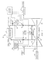
- FIG. 1 of the drawings there is schematically illustrated a power plant system having means for converting coal to power in a gas turbine, designated generally by the numeral 10.
- the system includes a pressurized combustor 12 into which coal is fed from a source at 14.
- the combustor can be either a bubbling fluidized bed combustor or a circulating fluidized bed combustor.
- a turbine designated generally by the numeral 16 includes a compressor 18 and an expander 20 powering a generator 22. Ambient air is drawn into the compressor at 24 and following compression is fed by way of a high pressure conduit 26 having a fast acting valve 28 to the pressurized combustor 12. The hot combustion gases from the combustor 12 are then filtered and passed along a high pressure conduit system 30 by way of a tight shutoff valve 32 to the expander 20.
- a bypass conduit 34 with a fast acting valve 36 connects between the outlet of the compressor and conduit 24 and the inlet to the expander.
- fast shutoff valve as used herein means a valve having a reasonably tight seal, and capable of full open to full closed positions in 0.2 to 1.0 seconds. These are typically butterfly valves by current technology.
- tight shutoff valve means a valve with a tight seal for one-hundred percent shutoff of gas flow and capable of full opened to full closed positions in from 2 to 10 seconds. These are typically gate valves and are designed for high temperature operation from around 649 degrees to about 982 degrees Celsius (1200 degrees to about 1800 degrees Fahrenheit).
- valves 28 and 36 are fast acting valves with modulating control capability of from zero to one-hundred percent air flow, with a tight seal and capability of full opened to full closed position in 0.2 to 1.0 seconds.
- valves are preferably hydraulically actuated for fast response by the emergency shutdown control system and will be substantially simultaneously actuated.
- the valves are designed for capability of operation up to 538 degrees Celsius (1000 degrees Fahrenheit) and are typically butterfly type valves, although other valves with these capabilities may be acceptable.
- the valve 32 for controlling the hot gases from the pressurized combustor is a tight shutoff valve.
- This valve is not required to modulate and will operate either fully open, passing 100% of the gas flow or fully closed, isolating the turbine from the fluidized bed. It may be hydraulically actuated with a tight seal capable of full closed to full opened or full opened to full closed in from two to ten seconds. Longer opening and/or closing times may be acceptable.
- This valve is preferably designed for a capability of operating at temperatures in the range of 816 to 982 degrees Celsius (1500 to 1800 degrees Fahrenheit).
- This valve is preferably a gate type valve, although other types of valves with these capabilities will be acceptable.
- a vent valve 40 is provided in conduit 30 for venting the hot gases from the pressurized combustion chamber.
- This valve is an on/off valve allowing zero or one-hundred percent hot gas flow, and may be hydraulically actuated with a tight seal and capable of full closed to full opened or full opened to full closed in from two to ten seconds. Longer opening and closing times may be acceptable in certain operations.
- the valve must have a capability of effective and reliable operation at temperatures in the range of 816 to 982 degrees Celsius (1500 to 1800 degrees Fahrenheit). This is preferably a gate type valve but other types of valves with the aforementioned capability will be acceptable.
- valve 36 can be designed so that the pressure drop across it is lower than the pressure drop across the combustor (12) and related components.
- valve 36 can be designed so that the pressure drop across it is lower than the pressure drop across the combustor (12) and related components.
- valve 32 can now be closed at a much slower rate, if desired to seal the hot gases in the combustor for a restart, or can be left open, If left open, the hot gases in the combustor will slowly be mixed with the bypassed air in increasing amounts, and the turbine will continue to decelerate.
- valve 32 is not a critical component in an emergency shutdown where a malfunction of the gas turbine or generator occurs. This also improves the capability of providing a tight shutoff of the valve in this location, namely valve 32, thereby also improving conditions during start-up.
- a pressurized gasification system a combination pressurized combustor and gasification system and pressurized combustor svstems wherein a topping combustor may be used.
- the topping combustor may be fueled by natural gas or by syn-gas.
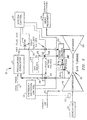
- the illustrated system wherein identical components will be referred to by the same reference numeral, differs from the prior power plant system in that it utilizes a topping combustor for further heating gases fed to the topping.
- compressed combustor air is fed by high pressure conduit 26 to pressurized combustor 12, which operates in the usual manner to provide hot gases by way of a conduit 30 to a topping combustor 52 which further heats and supplies hot gases to the expander 20.
- the topping combustor is fueled by gas from source 54 via line 56 and fast acting valve 58. This valve 58 is also controllable by the emergency shutdown control.
- a tight shutoff valve 32 controls the flow of gases from the pressurized combustor 12 to the combustor 52.
- a second tight shutoff valve 40 functions to vent hot gases from between the pressurized combustor and the combustor.
- a rapid bypass conduit 34 connects between the compressor and pressurized air conduit 26 and the combustor 52 for bypassing the pressurized combustor and is controlled by the fast acting valve 36.
- a redundant bypass 34' with fast acting valve 36' is provided directly to the inlet of the expander in case of failure of valve 36.
- the emergency shutdown control system 38 is connected to and capable of operating fast acting valves 28, 36 (and 36') and 58 for emergency shutdown control.
- the emergency control is also preferably provided with suitable speed or load sensing units or means 62. It may also include other sensors for determining problem conditions in the system.
- the overall control system 42 is connected to operate each of the valves, and also preferably includes suitable sensing means for sensing various parameters of the power plant system.
- This emergency shutdown system comprises fast acting valves in the high pressure air conduits between the compressor and the pressurized combustor and in a bypass line between the compressor and the expander. These high speed valves in case of an emergency shutdown are rapidly operated by simultaneously opening valve 36 and closing valve 28 (in 0.2 to 2.0 seconds) to bypass compressed combustor air directly to the expander.
- valve 36 In operation for an emergency shutdown, simultaneously valve 36 is rapidly opened and valve 28 is rapidly closed (in 0.2 to 2.0 seconds). Since the pressure drop across the pressurized combustor unit is substantially greater than the design pressure loss across the valve 36, these valves can be opened to a preset level that results in the colder compressor outlet air to be quickly bypassed or diverted in a controlled fashion to the expander inlet.
- the compressor air pressure is immediately higher than the pressurized combustor or gasifier outlet. This cooler air rapidly reduces the turbine inlet temperature, resulting in a deceleration of the turbine.
- valve 36 can be modulated to allow bleeding of the hot gases from the pressurized combustor through the turbine in a controlled fashion.
- valve 32 can be closed and the pressurized combustor be depressurized through valve 40.
- the depressurized hot syn-gases can be flared or retained for start-up.
- the compressor accounts for a significant load on the shaft.
- both the turbine and compressor will lose efficiency. This increases the relative resistance the compressor provides to acceleration. This will inhibit acceleration.
- the start-up procedure is initiated and performed substantially the same as that of a standard natural gas fired turbine start-up sequence.
- the start-up procedure is the same for both the pressurized combustor and gasifier and will be described in relation to both (pressurized combustor/gasifier).
- the start-up begins with valves 28, 32 and 40 closed and valve 36 open. Valve 32 as a tight shutoff valve will prevent the passage of hot gases back into the unheated combustor system. Once the engine achieves synchronous speed, it is available to begin the step pressurized combustor or gasifier purge. Simultaneously with the gas turbine start-up, the pressurized combustor/gasifier will be charged with a start-up bed inventory.
- valve 28 modulating to maintain about thirty percent by volume of air flow through the pressurized combustor/gasifier.
- Valve 36 will be full opened with valve 32 closed, and valves 40 full opened to pass air flow through the pressurized combustor/gasifier without pressurizing. After the engine reaches one-hundred percent NGP speed and the generator is synchronized, the pressurized combustor/gasifier and filter will be purged.
- the initial pressurized combustor/gasifier and filter purge is performed by modulating valve 28 open to obtain thirty percent of the volume air flow, and valve 40 is fully opened during this purge procedure.
- the purge is complete after five volumes of air of the pressurized combustor/gasifier, downstream piping and filter have been exchanged.
- pressurization cycle valve 28 will be modulated opened to flow compressor discharge air without over temperature of the turbine. This would be approximately twenty-five percent compressor total mass flow.
- Valve 36 is modulated closed to complete pressurized combustor/gasifier pressurization above turbine inlet pressure.
- Valve 32 remains fully closed and valve 40 is programmed closed after initial purge. Pressurization is accomplished by first closing valve 40 then modulating valve 28 open, which will allow engine compressor discharge air to fill and pressurize the pressurized combustor/gasifier.
- Compressor discharge air for pressurization will approach 700°F (371°C) and will also assist in the pressurized combustion/gasifier warm up cycle.
- valve 28 will be scheduled to limit volumetric flow to avoid carry over of bed inventory to filter due to high velocity in the combustor, and limit total mass flow to the pressurized combustor/gasifier to maintain gas turbine synchronous speed and avoid gas turbine over temperature.
- the pressurization will be completed after satisfying pressure across valve 32 being slightly higher on the pressurized combustor/gasifier side, with the engine operating at one-hundred percent synchronous speed and no load conditions. Valve 28 is at this point completely opened with negligible flow.
- Pressurized combustor/gasifier purge light off and warm up period will be carried out with valve 28 open and valve 36 (or 60) modulating to schedule proper flow to the pressurized combustor/gasifier.
- Valve 32 will be closed through purge, with valve 40 modulating to maintain pressure during the purge.
- valve 32 The pressurized combustor/gasifier purge at pressure is performed with valve 32 closed and valve 40 modulated to hold pressure while valve 36 is modulated to obtain thirty percent by volume air.
- valve 40 As valve 40 opens, or valve 36 closes, the start-up combustor exit temperature must increase to maintain the one-hundred percent synchronous speed, no load engine operation. The start-up combustor exit temperature will be used to control the turbine inlet temperature during the purge.
- valve 32 Upon completion of the purge, valve 32 will be programmed opened, then valve 40 will be programmed closed. Negligible flow across valve 32 will occur when the valve is opened due to equal pressure across the valve. Closing valve 40 will divert the flow from the combustor/gasifier to the turbine inlet.
- Valve 36 will modulate to maintain the minimum purge to the pressurized combustor/gasifier now discharging to the turbine inlet. It will also maximize the flow of air to the pressurized combustor/gasifier while maintaining the average turbine inlet temperature required to maintain one-hundred percent synchronous speed with stable engine operation.
- Valve 36 will modulate to control the air flow split between the start-up burner and the pressurized combustor/gasifier to maximize the flow of air to the PCG (pressurized combustor/gasifier) while maintaining the average turbine inlet temperature required to maintain one-hundred percent synchronous speed. The warm up continues until the pressurized combustor/gasifier discharge temperature is greater than the desired minimum.
- valve 36 The plant is now transferred to pressurized combustor/gasifier firing only by fully closing valve 36.
- the firing of the pressurized combustor/gasifier is continued up to a maximum rating on start-up fuel based on available compressor air flow.
- Engine speed is maintained as demand is shifted to the pressurized combustor/gasifier from the start-up combustor, with the engine expected to have nominal load to maintain constant speed and stable operation.
- the valve 36 is programmed closed to transfer from start-up combustor to design fuel firing. The transfer is complete with the start-up combustor air and fuel flow stopped, valve 38 fully opened, valve 36 fully closed, valve 32 fully opened, and valve 40 fully closed.
- Coal fuel feed is then begun and increased to raise turbine inlet temperature and plant electrical output up to rated gas turbine inlet temperature.
- valve 36 can be modulated open, allowing bypassing of colder compressor air to mix with the outer pressure combustor/gasifier exhaust at inlet of the gas turbine. This will lower the turbine inlet temperature, reducing the turbine load to one-hundred percent speed no load conditions. Fuel feed can then be stopped and valve 28 can be modulated closed as valve 36 is opened, allowing controlled deceleration of the turbine and the de-pressurization of the pressurized combustor/gasifier.
Landscapes
- Engineering & Computer Science (AREA)
- Chemical & Material Sciences (AREA)
- Combustion & Propulsion (AREA)
- Mechanical Engineering (AREA)
- General Engineering & Computer Science (AREA)
- Physics & Mathematics (AREA)
- Fluid Mechanics (AREA)
- Control Of Turbines (AREA)
- Engine Equipment That Uses Special Cycles (AREA)
Description
Claims (15)
- A method of operating a power plant under starting-up and emergency shutdown conditions, said power plant comprisingcharacterized bycoal fed pressurized means (10, 12) arranged to convert coal to hot pressurized combustor gases for powering a gas turbine (16),said gas turbine (16) having a compressor (18) arranged to pressurize combustion air for said pressurized means (10, 12) and expander means (20) arranged to receive and expand hot combustor gases for powering a generator (22) for generating electric power,a first conduit means (26) arranged to supply pressurized air to said pressurized means (10, 12),a second conduit means (34) arranged to supply pressurized air to said expander means (20),a third conduit means (30) arranged to supply the hot pressurized combustor gases to said expander means (20),a first valve means (28) in said first conduit means (26) arranged to control pressurized air therein,a second valve means (36, 36') in said second conduit means (34) arranged to control pressurized air therein, andthird valve means (32) in said third conduit means (30) for isolating pressurized gases to said expander means (20) during start-up and in preparation for restarting,control means (38) arranged to operate said first (28), second (36, 36') and third valve means (32), comprising the steps under emergency shutdown conditions of:simultaneously opening said second valve means (36, 36') and closing said first valve means (28) by said control means (38), such that combustion air having a higher pressure and being colder than the hot pressurized combustion gases in said third conduit means (30) is bypassed directly to the expander means (20), andmixing said bypassed combustion air with said hot pressurized combustor gases in said third conduit means (30) so as to decelerate the turbine (16),
the steps under emergency shutdown conditions ofsimultaneously opening said second valve means (36, 36') and closing said first valve means (28) within a period of from 0,2 to 2,0 seconds, andeither closing said third valve means (32) within a period of from 2 to 10 seconds or more to form a tight seal for 100% shutoff of gases or leaving open said third valve means (32). - A method according claim 1,
characterized by
the further step ofwhen closing said third valve means (32) within a period of from 2 to 10 seconds or more,
depressurizing said coal fed pressurized means (10, 12) through a vent valve means (40) arranged to vent gases from said pressurized means (10, 12), said vent valve means (40) being a shutoff valve means (40) comprising a tight seal for 100% shutoff of gases. - A method according claim 1,
characterized by
said third valve means (32) not being closed within the same period as said first (28) and second valve means (36, 36'). - A method according claim 1,
characterized by
preventing passage of hot gases back into the unheated pressurized means during start-up conditions by providing a 100 % tight seal for gases by means of closing said third valve means (32). - A power plant comprisingcharacterized in thatcoal fed pressurized means (10, 12) arranged to convert coal to hot pressurized combustor gases for powering a gas turbine (16),said gas turbine (16) having a compressor (18) arranged to pressurize combustion air for said pressurized means (10, 12) and expander means (20) arranged to receive and expand hot combustor gases for powering a generator (22) for generating electric power,a first conduit means (26) arranged to supply pressurized air to said pressurized means (10, 12),a second conduit means (34) arranged to supply pressurized air to said expander means (20),a third conduit means (30) arranged to supply the hot pressurized combustor gases to said expander means (20),a first valve means (28) in said first conduit means (26) arranged to control pressurized air therein,a second valve means (36, 36') in said second conduit means (34) arranged to control pressurized air therein,third valve means (32) in said third conduit means (30) for isolating pressurized gases to said expander means (20) during start-up and in preparation for restarting,control means (38) arranged to simultaneously open said second valve means (36, 36') and close said first valve means (28) such that combustion air having a higher pressure and being colder than the hot pressurized combustion gases in said third conduit means (30) is bypassed directly to the expander means (20) and said bypassed combustion air is mixed with said hot pressurized combustor gases in said third conduit means (30) so as to decelerate the turbine (16),said control means (28) is arranged to simultaneously open said second valve means (36, 36') and close said first valve means (28) within a period of from 0,2 to 2,0 seconds, andsaid third valve means is a first shutoff valve means (32) arranged to operate between a fully open and a fully closed position within a period of from 2 to 10 seconds or more and comprises a tight seal for 100% shutoff of gases.
- A power plant according to claim 5,
characterized in that
said first shutoff valve means (32) is a gate valve. - A power plant according to claim 5 or 6
characterized in that
said first shutoff valve means (32) is arranged to operate within a temperature range of about 649 to 982 degrees Celsius (about 1200 to 1800 degrees Fahrenheit) or about 816 to 982 degrees Celsius (about 1500 to 1800 degrees Fahrenheit). - A power plant according to any of claims 5 to 7,
further comprising a vent valve means (40) arranged to vent gases from said pressurized means (10, 12), said vent valve means (40) being a second shutoff valve means (40) comprising a tight seal for 100% shutoff of gases. - A power plant according to claim 8,
characterized in that
said second shutoff valve (40) is arranged to operate within a temperature range of about 649 to 982 degrees Celsius (about 1200 to 1800 degrees Fahrenheit) or about 816 to 982 degrees Celsius (about 1500 to 1800 degrees Fahrenheit). - A power plant according to claim 5,
characterized in that
said first valve means (28) is a butterfly valve. - A power plant according to claim 5,
characterized in that
said second valve means (36, 36') is a butterfly valve. - A power plant according to claim 5 or 10 or 11,
characterized in that
said first valve means (28) and said second valve means (36, 36') are arranged to operate at temperatures up to 538 degrees Celsius (1000 degrees Fahrenheit). - A power plant according to claim 5 or 8 or 11,
characterized in that
said first and said second valves means (28, 36, 36') are butterfly valves arranged to operate at temperatures up to 538 degrees Celsius (1000 degrees Fahrenheit), and said first and said second shutoff valves means (32, 40) are gate valves arranged to operate at temperatures of from about 816 up to about 982 degrees Celsius (1500 degrees up to about 1800 degrees Fahrenheit). - A power plant according to any of the claims 5 to 13,
characterized in that
said pressurized means (10, 12) is a combustor. - A power plant according to any of the claims 5 to 14,
characterized in that
said second valve means (36, 36') is designed such that that a pressure drop across it is lower than the pressure drop across the combustor (12).
Applications Claiming Priority (2)
| Application Number | Priority Date | Filing Date | Title |
|---|---|---|---|
| US30701 | 1993-03-12 | ||
| US08/030,701 US5309707A (en) | 1993-03-12 | 1993-03-12 | Control methods and valve arrangement for start-up and shutdown of pressurized combustion and gasification systems integrated with a gas turbine |
Publications (2)
| Publication Number | Publication Date |
|---|---|
| EP0615060A1 EP0615060A1 (en) | 1994-09-14 |
| EP0615060B1 true EP0615060B1 (en) | 1998-07-01 |
Family
ID=21855558
Family Applications (1)
| Application Number | Title | Priority Date | Filing Date |
|---|---|---|---|
| EP94103783A Expired - Lifetime EP0615060B1 (en) | 1993-03-12 | 1994-03-11 | A method of operating a power plant and a power plant |
Country Status (6)
| Country | Link |
|---|---|
| US (1) | US5309707A (en) |
| EP (1) | EP0615060B1 (en) |
| JP (1) | JP3034162B2 (en) |
| CA (1) | CA2117004C (en) |
| DE (1) | DE69411298T2 (en) |
| ES (1) | ES2120527T3 (en) |
Cited By (2)
| Publication number | Priority date | Publication date | Assignee | Title |
|---|---|---|---|---|
| DE10002084A1 (en) * | 2000-01-19 | 2001-08-02 | Siemens Ag | Gas and steam turbine plant |
| WO2016201338A1 (en) * | 2015-06-11 | 2016-12-15 | Eaton Corporation | Start up and shut down control strategies for volumetric energy recovery device |
Families Citing this family (47)
| Publication number | Priority date | Publication date | Assignee | Title |
|---|---|---|---|---|
| JP2680782B2 (en) * | 1994-05-24 | 1997-11-19 | 三菱重工業株式会社 | Coal-fired combined power plant combined with fuel reformer |
| US5630571A (en) * | 1995-10-16 | 1997-05-20 | General Motors Corporation | Exhaust flow control valve |
| ATE303425T1 (en) * | 1997-06-06 | 2005-09-15 | Texaco Development Corp | OXYGEN FLOW CONTROL FOR GASIFICATION |
| US6638014B2 (en) * | 2001-08-17 | 2003-10-28 | Alstom (Switzerland) Ltd | Valve arrangement for a power plant |
| US20060162338A1 (en) * | 2005-01-21 | 2006-07-27 | Pratt & Whitney Canada Corp. | Evacuation of hot gases accumulated in an inactive gas turbine engine |
| GB2423555A (en) * | 2005-02-26 | 2006-08-30 | Energetix Group Ltd | Pulsed fluid supply to positive displacement expander |
| US8671658B2 (en) | 2007-10-23 | 2014-03-18 | Ener-Core Power, Inc. | Oxidizing fuel |
| CN105089714B (en) | 2008-10-08 | 2017-10-17 | 三菱重工业株式会社 | Gas turbine and its method of operation |
| US8701413B2 (en) | 2008-12-08 | 2014-04-22 | Ener-Core Power, Inc. | Oxidizing fuel in multiple operating modes |
| US8621869B2 (en) * | 2009-05-01 | 2014-01-07 | Ener-Core Power, Inc. | Heating a reaction chamber |
| US20100275611A1 (en) * | 2009-05-01 | 2010-11-04 | Edan Prabhu | Distributing Fuel Flow in a Reaction Chamber |
| DE102009034304A1 (en) | 2009-07-21 | 2011-01-27 | Kwt Rosenkranz Gmbh | Power station for conversion of thermal energy into electric energy by gas turbine, has hot gas injector switched-on between heat source i.e. biomass furnace, and gas turbine, where biomass furnace is lined with fireclay |
| TWI439604B (en) * | 2009-10-30 | 2014-06-01 | Tsung Hsien Kuo | Method and apparatus for burning and working of solid fuel powder into open combustion gas turbine burner. |
| US9297304B2 (en) * | 2009-12-30 | 2016-03-29 | Rolls-Royce North American Technologies, Inc. | Gas turbine engine system with bleed air powered auxiliary engine |
| US9086018B2 (en) | 2010-04-23 | 2015-07-21 | Hamilton Sundstrand Corporation | Starting a gas turbine engine to maintain a dwelling speed after light-off |
| IT1401923B1 (en) | 2010-09-09 | 2013-08-28 | Nuovo Pignone Spa | METHODS AND DEVICES FOR TESTING A LOW-SPEED LOW-TIME ROTOR IN A TURBOMACCHINE |
| US8726628B2 (en) | 2010-10-22 | 2014-05-20 | General Electric Company | Combined cycle power plant including a carbon dioxide collection system |
| US8744634B2 (en) * | 2010-11-19 | 2014-06-03 | General Electric Company | Safety instrumented system (SIS) for a turbine system |
| US8832563B2 (en) | 2011-07-27 | 2014-09-09 | General Electric Company | Automatic detection of designated controller in a distributed control system using a web client |
| EP2559862B1 (en) * | 2011-08-19 | 2021-11-10 | Ansaldo Energia IP UK Limited | Control of a blow-off valve responsive to a sudden de-loading of a gas turbine |
| US9273606B2 (en) | 2011-11-04 | 2016-03-01 | Ener-Core Power, Inc. | Controls for multi-combustor turbine |
| US9279364B2 (en) | 2011-11-04 | 2016-03-08 | Ener-Core Power, Inc. | Multi-combustor turbine |
| FR2986571B1 (en) * | 2012-02-06 | 2014-02-21 | Eurocopter France | DEVICE AND METHOD FOR REGULATING A TURBOMOTOR, AND AIRCRAFT |
| US9381484B2 (en) | 2012-03-09 | 2016-07-05 | Ener-Core Power, Inc. | Gradual oxidation with adiabatic temperature above flameout temperature |
| US9359947B2 (en) | 2012-03-09 | 2016-06-07 | Ener-Core Power, Inc. | Gradual oxidation with heat control |
| US9534780B2 (en) | 2012-03-09 | 2017-01-03 | Ener-Core Power, Inc. | Hybrid gradual oxidation |
| US9347664B2 (en) | 2012-03-09 | 2016-05-24 | Ener-Core Power, Inc. | Gradual oxidation with heat control |
| US9234660B2 (en) | 2012-03-09 | 2016-01-12 | Ener-Core Power, Inc. | Gradual oxidation with heat transfer |
| US9267432B2 (en) | 2012-03-09 | 2016-02-23 | Ener-Core Power, Inc. | Staged gradual oxidation |
| US9273608B2 (en) | 2012-03-09 | 2016-03-01 | Ener-Core Power, Inc. | Gradual oxidation and autoignition temperature controls |
| US9359948B2 (en) | 2012-03-09 | 2016-06-07 | Ener-Core Power, Inc. | Gradual oxidation with heat control |
| US9567903B2 (en) | 2012-03-09 | 2017-02-14 | Ener-Core Power, Inc. | Gradual oxidation with heat transfer |
| US8926917B2 (en) | 2012-03-09 | 2015-01-06 | Ener-Core Power, Inc. | Gradual oxidation with adiabatic temperature above flameout temperature |
| US9194584B2 (en) | 2012-03-09 | 2015-11-24 | Ener-Core Power, Inc. | Gradual oxidation with gradual oxidizer warmer |
| US9017618B2 (en) | 2012-03-09 | 2015-04-28 | Ener-Core Power, Inc. | Gradual oxidation with heat exchange media |
| US9328916B2 (en) | 2012-03-09 | 2016-05-03 | Ener-Core Power, Inc. | Gradual oxidation with heat control |
| US9328660B2 (en) | 2012-03-09 | 2016-05-03 | Ener-Core Power, Inc. | Gradual oxidation and multiple flow paths |
| US8980193B2 (en) | 2012-03-09 | 2015-03-17 | Ener-Core Power, Inc. | Gradual oxidation and multiple flow paths |
| US8807989B2 (en) | 2012-03-09 | 2014-08-19 | Ener-Core Power, Inc. | Staged gradual oxidation |
| US9206980B2 (en) | 2012-03-09 | 2015-12-08 | Ener-Core Power, Inc. | Gradual oxidation and autoignition temperature controls |
| US9371993B2 (en) | 2012-03-09 | 2016-06-21 | Ener-Core Power, Inc. | Gradual oxidation below flameout temperature |
| US8980192B2 (en) | 2012-03-09 | 2015-03-17 | Ener-Core Power, Inc. | Gradual oxidation below flameout temperature |
| US9353946B2 (en) | 2012-03-09 | 2016-05-31 | Ener-Core Power, Inc. | Gradual oxidation with heat transfer |
| CN103472816B (en) * | 2013-08-29 | 2016-02-17 | 国家电网公司 | A kind of automatic start-stop detection method and system being applied to oil system |
| DE102014200980A1 (en) * | 2014-01-21 | 2015-07-23 | Siemens Aktiengesellschaft | Method for controlling a gas turbine |
| US10851677B2 (en) * | 2015-08-28 | 2020-12-01 | Ingersoll-Rand Industrial U.S., Inc. | Boiler with integrated air compressor |
| DE102017122380B4 (en) * | 2017-09-27 | 2021-09-23 | Spanner RE2 GmbH | Generator system for generating electrical energy |
Family Cites Families (9)
| Publication number | Priority date | Publication date | Assignee | Title |
|---|---|---|---|---|
| SE431359B (en) * | 1982-06-14 | 1984-01-30 | Stal Laval Turbin Ab | GASTURBINANLEGGNING |
| SE431360B (en) * | 1982-06-14 | 1984-01-30 | Stal Laval Turbin Ab | GASTURBINANLEGGNING |
| SE458047B (en) * | 1986-01-24 | 1989-02-20 | Asea Stal Ab | PROVIDED TO REGULATE A PFBC PLANT FOR OPERATING DAMAGE IN A GAS TURBIN FITTING AND A PFBC PLANT WITH EQUIPMENT BEFORE SUCH REGULATION |
| SE456757B (en) * | 1987-03-09 | 1988-10-31 | Asea Stal Ab | Pre-combustion power plant with high pressure and a gas turbine powered by the pre-combustion gases |
| SE459353B (en) * | 1987-04-14 | 1989-06-26 | Abb Stal Ab | ENERGY CONSTRUCTION WITH HEAT EXCHANGER IN BREASER DEVICE FOR HOT GASES |
| SE464715B (en) * | 1987-12-02 | 1991-06-03 | Asea Stal Ab | PROVIDED TO REGULATE A PFBC PLANT FOR OPERATING DAMAGE IN A GAS TURBIN FITTING AND A PFBC PLANT WITH EQUIPMENT BEFORE SUCH REGULATION |
| SE459988B (en) * | 1987-12-23 | 1989-08-28 | Abb Stal Ab | COULD COOL BEDDING MATERIAL IN A PFBC POWER PLANT AND PFBC POWER PLANT WITH A REFRIGERATOR CONNECTED TO THE BEDDER |
| EP0361065A1 (en) * | 1988-09-28 | 1990-04-04 | Westinghouse Electric Corporation | Power generating method using solid fuel for a gas turbine |
| JP2954754B2 (en) * | 1991-07-22 | 1999-09-27 | 株式会社日立製作所 | Operation control device for gas turbine system and pressurized fluidized bed boiler power plant |
-
1993
- 1993-03-12 US US08/030,701 patent/US5309707A/en not_active Expired - Fee Related
-
1994
- 1994-03-04 CA CA002117004A patent/CA2117004C/en not_active Expired - Fee Related
- 1994-03-11 EP EP94103783A patent/EP0615060B1/en not_active Expired - Lifetime
- 1994-03-11 JP JP6041352A patent/JP3034162B2/en not_active Expired - Lifetime
- 1994-03-11 ES ES94103783T patent/ES2120527T3/en not_active Expired - Lifetime
- 1994-03-11 DE DE69411298T patent/DE69411298T2/en not_active Expired - Fee Related
Cited By (4)
| Publication number | Priority date | Publication date | Assignee | Title |
|---|---|---|---|---|
| DE10002084A1 (en) * | 2000-01-19 | 2001-08-02 | Siemens Ag | Gas and steam turbine plant |
| DE10002084C2 (en) * | 2000-01-19 | 2001-11-08 | Siemens Ag | Gas and steam turbine plant |
| US6889506B2 (en) | 2000-01-19 | 2005-05-10 | Siemens Aktiengesellschaft | Gas and steam turbine installation |
| WO2016201338A1 (en) * | 2015-06-11 | 2016-12-15 | Eaton Corporation | Start up and shut down control strategies for volumetric energy recovery device |
Also Published As
| Publication number | Publication date |
|---|---|
| JPH06299866A (en) | 1994-10-25 |
| CA2117004C (en) | 1999-01-26 |
| DE69411298D1 (en) | 1998-08-06 |
| JP3034162B2 (en) | 2000-04-17 |
| ES2120527T3 (en) | 1998-11-01 |
| EP0615060A1 (en) | 1994-09-14 |
| CA2117004A1 (en) | 1994-09-13 |
| DE69411298T2 (en) | 1999-02-11 |
| US5309707A (en) | 1994-05-10 |
Similar Documents
| Publication | Publication Date | Title |
|---|---|---|
| US5309707A (en) | Control methods and valve arrangement for start-up and shutdown of pressurized combustion and gasification systems integrated with a gas turbine | |
| US8176723B2 (en) | Apparatus for starting a steam turbine against rated pressure | |
| EP1186761B1 (en) | Energy recovery from compressor discharge bleed air in gas turbine plants | |
| KR100313824B1 (en) | Gas turbine plant | |
| US7500349B2 (en) | Power plant and operating method | |
| EP0559685B1 (en) | Steam injection system | |
| US20050138930A1 (en) | Indirectly heated gas turbine control system | |
| JP2000161014A (en) | Combined power generation equipment | |
| US20140305132A1 (en) | Method for starting up a gas and steam turbine system | |
| US6679046B2 (en) | Single-shaft combined plant | |
| US5388411A (en) | Method of controlling seal steam source in a combined steam and gas turbine system | |
| US4362013A (en) | Method for operating a combined plant | |
| US20200116086A1 (en) | Method for starting a gas turbine | |
| JP2856860B2 (en) | Gas turbine equipment | |
| JPS6232181A (en) | Device for energy recovery from gas generated in regeneration tower of fluid catalytic cracking equipment | |
| Bammert et al. | Operation and Control of the 50-MW Closed-Cycle Helium Turbine Oberhausen | |
| CN114483215A (en) | Emergency steam turbine generator unit for nuclear power station | |
| US4192489A (en) | Control system for an installation utilizing pressure energy of outgoing blast-furnace gas | |
| GB2049816A (en) | A Gas Turbine Power Plant having an Air-Cooled Pressurized Fluidized Bed Combustor | |
| JPS6239653B2 (en) | ||
| WO2015124909A1 (en) | Improved fuel supply system for a gas turbine | |
| JP4025206B2 (en) | Control device for biomass gas turbine | |
| JPS6239655B2 (en) | ||
| JP2766370B2 (en) | Starting device for combined cycle power generation unit | |
| RU1815372C (en) | Control system for gas-turbine engine |
Legal Events
| Date | Code | Title | Description |
|---|---|---|---|
| PUAI | Public reference made under article 153(3) epc to a published international application that has entered the european phase |
Free format text: ORIGINAL CODE: 0009012 |
|
| 17P | Request for examination filed |
Effective date: 19940311 |
|
| AK | Designated contracting states |
Kind code of ref document: A1 Designated state(s): DE ES FR GB |
|
| 17Q | First examination report despatched |
Effective date: 19950804 |
|
| RAP1 | Party data changed (applicant data changed or rights of an application transferred) |
Owner name: FOSTER WHEELER ENERGIA OY |
|
| GRAG | Despatch of communication of intention to grant |
Free format text: ORIGINAL CODE: EPIDOS AGRA |
|
| GRAG | Despatch of communication of intention to grant |
Free format text: ORIGINAL CODE: EPIDOS AGRA |
|
| GRAG | Despatch of communication of intention to grant |
Free format text: ORIGINAL CODE: EPIDOS AGRA |
|
| GRAH | Despatch of communication of intention to grant a patent |
Free format text: ORIGINAL CODE: EPIDOS IGRA |
|
| GRAH | Despatch of communication of intention to grant a patent |
Free format text: ORIGINAL CODE: EPIDOS IGRA |
|
| GRAA | (expected) grant |
Free format text: ORIGINAL CODE: 0009210 |
|
| AK | Designated contracting states |
Kind code of ref document: B1 Designated state(s): DE ES FR GB |
|
| REF | Corresponds to: |
Ref document number: 69411298 Country of ref document: DE Date of ref document: 19980806 |
|
| ET | Fr: translation filed | ||
| REG | Reference to a national code |
Ref country code: ES Ref legal event code: FG2A Ref document number: 2120527 Country of ref document: ES Kind code of ref document: T3 |
|
| PGFP | Annual fee paid to national office [announced via postgrant information from national office to epo] |
Ref country code: FR Payment date: 19990208 Year of fee payment: 6 |
|
| PGFP | Annual fee paid to national office [announced via postgrant information from national office to epo] |
Ref country code: GB Payment date: 19990216 Year of fee payment: 6 |
|
| PGFP | Annual fee paid to national office [announced via postgrant information from national office to epo] |
Ref country code: DE Payment date: 19990226 Year of fee payment: 6 |
|
| PGFP | Annual fee paid to national office [announced via postgrant information from national office to epo] |
Ref country code: ES Payment date: 19990312 Year of fee payment: 6 |
|
| PLBQ | Unpublished change to opponent data |
Free format text: ORIGINAL CODE: EPIDOS OPPO |
|
| PLBI | Opposition filed |
Free format text: ORIGINAL CODE: 0009260 |
|
| PLBF | Reply of patent proprietor to notice(s) of opposition |
Free format text: ORIGINAL CODE: EPIDOS OBSO |
|
| 26 | Opposition filed |
Opponent name: ASEA BROWN BOVERI AB Effective date: 19990401 |
|
| PG25 | Lapsed in a contracting state [announced via postgrant information from national office to epo] |
Ref country code: GB Free format text: LAPSE BECAUSE OF NON-PAYMENT OF DUE FEES Effective date: 20000311 |
|
| PG25 | Lapsed in a contracting state [announced via postgrant information from national office to epo] |
Ref country code: ES Free format text: LAPSE BECAUSE OF NON-PAYMENT OF DUE FEES Effective date: 20000313 |
|
| PLBO | Opposition rejected |
Free format text: ORIGINAL CODE: EPIDOS REJO |
|
| GBPC | Gb: european patent ceased through non-payment of renewal fee |
Effective date: 20000311 |
|
| PG25 | Lapsed in a contracting state [announced via postgrant information from national office to epo] |
Ref country code: FR Free format text: LAPSE BECAUSE OF NON-PAYMENT OF DUE FEES Effective date: 20001130 |
|
| REG | Reference to a national code |
Ref country code: FR Ref legal event code: ST |
|
| PG25 | Lapsed in a contracting state [announced via postgrant information from national office to epo] |
Ref country code: DE Free format text: LAPSE BECAUSE OF NON-PAYMENT OF DUE FEES Effective date: 20010103 |
|
| PLBN | Opposition rejected |
Free format text: ORIGINAL CODE: 0009273 |
|
| STAA | Information on the status of an ep patent application or granted ep patent |
Free format text: STATUS: OPPOSITION REJECTED |
|
| 27O | Opposition rejected |
Effective date: 20001104 |
|
| REG | Reference to a national code |
Ref country code: ES Ref legal event code: FD2A Effective date: 20011010 |