EP0615054B1 - Coiled tubing actuated sampler - Google Patents
Coiled tubing actuated sampler Download PDFInfo
- Publication number
- EP0615054B1 EP0615054B1 EP94301727A EP94301727A EP0615054B1 EP 0615054 B1 EP0615054 B1 EP 0615054B1 EP 94301727 A EP94301727 A EP 94301727A EP 94301727 A EP94301727 A EP 94301727A EP 0615054 B1 EP0615054 B1 EP 0615054B1
- Authority
- EP
- European Patent Office
- Prior art keywords
- bore
- well
- pressure
- coiled tubing
- actuator
- Prior art date
- Legal status (The legal status is an assumption and is not a legal conclusion. Google has not performed a legal analysis and makes no representation as to the accuracy of the status listed.)
- Expired - Lifetime
Links
- 239000012530 fluid Substances 0.000 claims description 57
- 238000005070 sampling Methods 0.000 claims description 53
- 238000000034 method Methods 0.000 claims description 7
- 230000000903 blocking effect Effects 0.000 description 26
- 239000003921 oil Substances 0.000 description 21
- 238000007667 floating Methods 0.000 description 9
- 230000015572 biosynthetic process Effects 0.000 description 3
- 230000005484 gravity Effects 0.000 description 2
- 239000010720 hydraulic oil Substances 0.000 description 2
- 230000002706 hydrostatic effect Effects 0.000 description 2
- 230000000977 initiatory effect Effects 0.000 description 2
- 238000003825 pressing Methods 0.000 description 2
- XUIMIQQOPSSXEZ-UHFFFAOYSA-N Silicon Chemical compound [Si] XUIMIQQOPSSXEZ-UHFFFAOYSA-N 0.000 description 1
- 239000004568 cement Substances 0.000 description 1
- 238000004891 communication Methods 0.000 description 1
- 238000010276 construction Methods 0.000 description 1
- 230000008878 coupling Effects 0.000 description 1
- 238000010168 coupling process Methods 0.000 description 1
- 238000005859 coupling reaction Methods 0.000 description 1
- 238000005553 drilling Methods 0.000 description 1
- 230000001788 irregular Effects 0.000 description 1
- 238000004519 manufacturing process Methods 0.000 description 1
- 230000000717 retained effect Effects 0.000 description 1
- 238000010008 shearing Methods 0.000 description 1
- 229910052710 silicon Inorganic materials 0.000 description 1
- 239000010703 silicon Substances 0.000 description 1
- 239000007787 solid Substances 0.000 description 1
- 230000001960 triggered effect Effects 0.000 description 1
Images






Classifications
-
- E—FIXED CONSTRUCTIONS
- E21—EARTH OR ROCK DRILLING; MINING
- E21B—EARTH OR ROCK DRILLING; OBTAINING OIL, GAS, WATER, SOLUBLE OR MELTABLE MATERIALS OR A SLURRY OF MINERALS FROM WELLS
- E21B19/00—Handling rods, casings, tubes or the like outside the borehole, e.g. in the derrick; Apparatus for feeding the rods or cables
- E21B19/22—Handling reeled pipe or rod units, e.g. flexible drilling pipes
-
- E—FIXED CONSTRUCTIONS
- E21—EARTH OR ROCK DRILLING; MINING
- E21B—EARTH OR ROCK DRILLING; OBTAINING OIL, GAS, WATER, SOLUBLE OR MELTABLE MATERIALS OR A SLURRY OF MINERALS FROM WELLS
- E21B34/00—Valve arrangements for boreholes or wells
- E21B34/06—Valve arrangements for boreholes or wells in wells
- E21B34/10—Valve arrangements for boreholes or wells in wells operated by control fluid supplied from outside the borehole
- E21B34/108—Valve arrangements for boreholes or wells in wells operated by control fluid supplied from outside the borehole with time delay systems, e.g. hydraulic impedance mechanisms
-
- E—FIXED CONSTRUCTIONS
- E21—EARTH OR ROCK DRILLING; MINING
- E21B—EARTH OR ROCK DRILLING; OBTAINING OIL, GAS, WATER, SOLUBLE OR MELTABLE MATERIALS OR A SLURRY OF MINERALS FROM WELLS
- E21B49/00—Testing the nature of borehole walls; Formation testing; Methods or apparatus for obtaining samples of soil or well fluids, specially adapted to earth drilling or wells
- E21B49/08—Obtaining fluid samples or testing fluids, in boreholes or wells
- E21B49/081—Obtaining fluid samples or testing fluids, in boreholes or wells with down-hole means for trapping a fluid sample
- E21B49/0815—Sampling valve actuated by tubing pressure changes
Definitions
- the present invention relates to a coiled tubing conveyed sampling apparatus, and to a method of obtaining a sample of well fluid.
- Such a highly deviated or horizontal well typically includes a substantially vertical portion followed by a radiused portion which leads to a substantially horizontal portion of the well bore which runs for substantial distances horizontally through a subsurface formation from which oil or gas is to be produced.
- the present invention provides a sampler constructed to be run on coiled tubing.
- the sampler is constructed to be actuated in response to an increase in pressure within the coiled tubing and thus provides positive surface control of actuation of the sampler.
- the sampler is especially useful in horizontal wells since, unlike wireline conveyed samplers, the coiled tubing can be used to move the sampler into the horizontal portion of the well.
- a coiled tubing conveyed sampling apparatus which comprises an actuator housing having a housing interior and having a proximal housing end including connector means for connecting said housing to a coiled tubing string so that a tubing bore of said coiled tubing string communicates with said housing interior; check valve means, disposed in said housing interior for allowing well fluid from a well bore to fill said tubing bore of said coiled tubing string as said sampling apparatus is run into said well bore on said coiled tubing string, and for isolating said tubing bore from said well bore when pressure in said tubing bore exceeds pressure in said well bore; a sampling tool attached to said actuator housing; and pressure responsive actuator means disposed in said housing interior for actuating said sampling tool in response to pressure in said tubing bore exceeding pressure in said well bore by a first value so that a well fluid sample is trapped in said sampling tool.
- a relief and drain valve is also provided for relieving pressure from the tubing bore to the well bore when pressure in the tubing bore exceeds pressure in the well bore by a second value greater than said first value.
- the relief and drain valve also allows fluid to drain from the tubing bore when the coiled tubing string and sampling apparatus are subsequently retrieved from the well bore.
- Methods of taking well fluid samples using such an apparatus include the steps of:
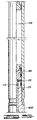
- Fig. 1 is a schematic elevational view of a highly deviated well including a vertical portion and a horizontal portion. A coiled tubing string carrying an embodiment of sampling apparatus of the present invention is shown in place with the sampling apparatus located in the horizontal portion of the well.
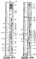
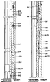
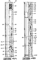
- Figs. 2A-2L comprise an elevational partly sectioned view of one embodiment of sampling apparatus of the present invention in an initial position as it would be run into the well.
- the one-way check valve is shown in an open position so that well fluid is filling the tubing string on which the sampling apparatus is being run into the well.
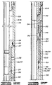
- FIGS. 3A-3G comprise a view similar to FIGS. 2A-2G of the upper portion of the apparatus of FIGS. 2A-2L showing the sampling apparatus in an intermediate position wherein the sampling tool has been actuated, and a sample is flowing into the sample chamber.
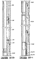
- FIGS. 4A-4G comprise an elevation partly sectioned view similar to FIGS. 2A-2G again of only the upper portion of the tool showing the tool in a final position wherein the sample chamber is closed trapping a sample therein and wherein a relief valve has opened to allow the coiled tubing string to drain as the coiled tubing string and sampler apparatus are retrieved from the well.
- a typical highly deviated well is thereshown and generally designated by the numeral 10.
- the well 10 is constructed by drilling a bore hole 12 having a substantially vertical portion 14, a radiused portion 16, and a generally horizontal or substantially horizontal bore hole portion 18. It will be understood that the generally horizontal portion 18 need not be exactly horizontal. It does, however, have such a shallow slope that conventional wireline conveyed tools cannot be run into the horizontal portion of the well.
- the well bore 14, and particularly the horizontal portion 18 thereof is shown as intersecting a subsurface formation 20 from which oil or gas is to be produced.
- the well 10 is shown as having casing 22 cemented in the vertical portion and part of the horizontal portion thereof by cement 24.
- the distal part of the horizontal portion 18 thereof remains uncased.
- a length of slotted liner 23 extends from the distal end of casing 22 into the uncased portion of the hole.
- Liner 23 has slots 25 which communicate with the open bore hole and thus with formation 20.
- Production tubing or drill pipe 27 may be placed in the casing 22, and is sealed near the distal end thereof by packer 29.
- Coiled tubing injectors 28 are used to pass a coiled tubing string 30 from a conventional coiled tubing reel (not shown) down through the well head 26 into the well 10.
- a source of fluid under pressure 34 which is communicated with the coiled tubing string 30 through a pressure supply line 36 having a control valve 38 disposed therein. It will be understood that the pressure supply conduit 36 will be connected to the coiled tubing reel (not shown) in a conventional manner so as to supply fluid pressure to a tubing bore of the coiled tubing string 30.
- a sampler apparatus 40 is schematically illustrated in FIG. 1 as being carried on the lower end of coiled tubing string 30 into the horizontal portion 18 of bore hole 12. It will be understood that other tools could be run on the tubing string 30 in addition to the sampler 40, and additionally that centralizers or packers could be run therewith to position the sampler 40 within the bore hole as desired.
- the horizontal portion of the well could be an open hole with no casing or liner.
- aspects of the present invention are equally suitable to use in the vertical portion of a well. Certain aspects of the invention, however, are particularly useful in taking a sample of fluids being produced into a horizontal portion of a well as illustrated in FIG. 1.
- the use of the coiled tubing string 30 to run the sampler apparatus 40 into the horizontal portion of the well provides accurate and easy placement of the sampler apparatus 40 at any desired location along the horizontal portion 18 of the bore hole 12. This cannot be accomplished with wireline conveyed tools which depend on gravity as a motive force and which cannot be moved by the wireline any substantial distance into the horizontal portion of the well.
- FIGS. 2A-2L comprise an elevation partly sectioned view of the sampler apparatus 40 in its initial or run-in position as it would be in when being run down into the well 10. As is further described below, as the apparatus 40 is run down into the well 10, well fluid is allowed to flow into the coiled tubing string 30 to fill the coiled tubing string 30.
- the sampler apparatus 40 includes a housing assembly generally designated by the numeral 42.
- the housing assembly 42 is made up of a number of tubular sections threadedly connected together with appropriate seals therebetween.
- the housing assembly 42 includes from top to bottom an upper actuator housing section 44, a lower actuator housing section 46, a first actuator rod housing section 48, a first dump chamber housing section 50, a first blocking valve housing section 52, a first orifice housing section 54, a first oil housing section 56, a first sample valve housing section 58, a first sample chamber housing section 60, a second actuating rod housing section 62, a second dump chamber housing section 64, a second blocking valve housing section 66, a second orifice housing section 68, a second oil housing section 70, a second sample valve housing section 72, a second sample chamber housing section 74, a housing coupling 76 and a housing lower end cap 78.
- a bore 79 of the upper actuator housing section 44 defines an interior central housing passage 80 in upper actuator housing section 44. Passage 80 may also be referred to as interior 80 or as an actuating chamber 80.
- Upper actuator housing section 44 has an open proximal end 82 having internal threads 84 defined therein for connection of the housing assembly 42 to the coiled tubing string 30 in a conventional manner.
- the threads 84 may be referred to as a connector means 84 for connecting the sampler apparatus 40 to the coiled tubing string 30.
- proximal and distal are used to refer to relative portions of the apparatus 40 as viewed from the surface of the well 10.
- the end 82 of housing assembly 42 which is closest to the upper end of the well 10 is referred to as the upper or proximal end
- the other end defined by housing lower end cap 78 is referred to as the lower or distal end of the housing assembly 42.
- proximal and distal are often used herein particularly when describing movements within the horizontal portion 18 of the well since such movements are not truly up and down in a gravitational sense although they may be considered as upward and downward movements in relation to the bore hole 12.
- the upper actuator housing section 44 has a plurality of relief and drain ports 86 defined radially therethrough to communicate a housing exterior 88 with the housing interior passage 80.
- the upper actuator housing section 44 also includes a plurality of run-in fill ports or passages 90 defined therethrough which also communicate the housing exterior 88 with the interior housing passage 80 of actuator housing section 44.
- a relief valve sleeve 92 and an actuator sleeve 94 are threadedly connected together at 95 and are slidably received within the bore 79 of upper actuator housing section 44.
- Relief valve sleeve 92 and actuator sleeve 94 are shown in FIG. 2A in their initial position as they would be in when the apparatus 40 is run into the well 10. In this initial position, relief valve sleeve 92 has upper and lower O-ring seals 96 and 98 located above and below the relief ports 86, respectively, so that the relief ports 86 are blocked by the relief valve sleeve 92.
- Relief valve sleeve 92 and actuator sleeve 94 have bores 100 and 102, respectively, defined therein which are communicated with each other and communicated by the bore 79 with the open upper end 82 of housing 42.
- Actuator sleeve 94 has a plurality of ports 104 defined radially therethrough which are aligned with the run-in fill ports 90 so that well fluids from the well 10 surrounding the housing exterior 88 may flow through the fill ports 90 and ports 104 into the actuating chamber 80 and up into the tubing bore of coiled tubing string 30 to fill the coiled tubing string 30 as it is run into the well.
- Relief valve sleeve 92 has a retaining cage member 106 defined therein which retains a ball check 108 in place therebelow.
- the upper end of actuator sleeve 94 carries an O-ring seat 110 for the ball check 108.
- the ball check 108 is seen in an uppermost or open position against the cage 106 as it would be in when well fluid is running through the ports 90 and 104 and up through the bores 102 and 100 to fill the coiled tubing string 100. This fluid flows around the ball check 108 through an irregular passageway 112 which generally flows out around and back in past the cage 106.
- the ball check 108, seat 110 and retaining cage 106 may be collectively referred to as a one-way check valve 114 disposed in the housing interior or actuating chamber 80 for allowing well fluid from the well to fill the tubing bore of the coiled tubing string 30 as the sampling apparatus 40 is run into the well bore 12 on the coiled tubing string 30, and for subsequently isolating the tubing bore of coiled tubing string 30 from the well bore 12 when pressure in the tubing bore exceeds the pressure in the well bore.
- the actuator sleeve 94 carries an O-ring seal 116 which seals against bore 79 of upper actuator housing section 44 below the check valve means 114.
- the actuator sleeve 94 has a lower enlarged diameter sleeve bore 118 defined in its lower end.
- An actuator shaft 120 has its upper end received in lower sleeve bore 118 and the two pieces are held together by a plurality of shear pins 122.
- the actuator shaft 120 has a cylindrical outer surface 124 closely received within a lower bore 126 of upper actuator housing section 44 with an O-ring seal 128 provided therebetween.
- a radially outward extending annular flange portion 130 of actuator shaft 120 has an enlarged diameter cylindrical outer surface 132 closely received within a bore 134 of lower actuator housing section 46 with an O-ring seal 136 provided therebetween. Below flange 130 the lower portion of cylindrical outer surface 124 of actuator shaft 120 is received within a reduced diameter bore 138 of lower actuator housing section 46 with an O-ring seal 140 provided therebetween.
- the actuator shaft 120 in its initial position, has its flange 130 abutting a lower end 142 of upper actuator housing section 44.
- the flange 130 is spaced by a distance 144 from an upward facing shoulder 146 of lower actuator housing section 46. As is further described below, this will allow a travel through the distance 144 by the actuator shaft 120, actuator sleeve 94 and relief valve sleeve 92 as those components move from the position of FIGS. 2A-2D to the position of FIGS. 3A-3D.
- Relief holes such as 148 prevent hydraulic blockage of that travel.
- a lower end 150 of actuator shaft 120 abuts an upper end 152 of a first actuator rod 154.
- the first actuator rod 154 is initially retained in the position of FIGS. 2B-2D relative to first actuator rod housing section 48 by a plurality of shear pins 156.
- first actuator rod 154 In this initial position of first actuator rod 154, its abutment with the actuator shaft 120 holds the actuator shaft 120, actuator sleeve 94 and relief valve sleeve 92 in their initial positions illustrated in FIGS. 2A-2B.
- those portions of the sampler apparatus 40 located below the lower actuator housing section 46 make up a tandem sample chamber.
- a single sample chamber or more than two sample chambers could be provided.
- the entire assembly of relief valve sleeve 92, actuator sleeve 94 and actuator shaft 120, along with the one-way check valve 114 may be said to make up an actuator piston or hydraulic actuator device which will provide a downward force on first actuator rod 154 to shear the shear pins 156 when fluid pressure within the tubing bore of coiled tubing string 30 reaches a first value as determined primarily by the selection and construction of the shear pins 156. It will be understood that the pressure within the tubing bore of coiled tubing string 30 acts downward across the entire circular area defined within the O-ring seal 116 as it contacts bore 79 below the check valve 114.
- FIGS. 3A-3G illustrate an intermediate position of the sampling apparatus 40.
- sufficient pressure has been applied to the tubing bore of coiled tubing string 30 to shear the shear pins 156 and move the actuator shaft 120, actuator sleeve 94 and relief valve sleeve 92 downward through the travel 144 until the shoulder 130 of actuator shaft 120 bottoms out against upward facing shoulder 146 of lower actuator housing section 46 as seen in FIG. 3B, or until lower end 150 of actuator shaft 120 abuts the upper end of first actuator rod housing section 48. It is apparent that this downward movement also forces the first actuator rod 154 downward through that same distance 144, which as further described below will actuate the first one of the tandem sample chambers.
- the relief valve sleeve 92 and actuator sleeve 94, and their frangible connection to actuator shaft 120 by shear pins 122, in combination with the relief ports 86 can be described as providing a relief and drain valve means for relieving pressure from the tubing bore of coiled tubing string 30 to the well bore 12 when pressure in the tubing bore exceeds pressure in the well bore by a second value greater than the first valve at which the shear pins 156 initially shear to allow actuation of the sampling device located therebelow. This second value is determined by the selection of shear pins 122.
- This relief and drain valve means also allows fluid to drain from the tubing bore of the coiled tubing string 30 when the sampling apparatus 40 and coiled tubing string 30 are retrieved from the well.
- the relief valve sleeve 92 and actuator sleeve 94 collectively can be referred to as a sliding sleeve valve 92, 94 received within the housing interior 80 and slidable from the first position shown in FIGS. 2A-2B when the relief ports 86 are closed to the second position shown in FIGS. 4A-4B wherein the relief ports 86 are open.
- This sliding sleeve valve can be said to carry the check valve means 114 therein.
- the shear pins 122 can be generally described as a releasable attachment means 122 for initially releasably attaching the actuator sleeve 94 and relief valve sleeve 92 to the actuator shaft 120 and for releasing the actuator sleeve 94 and relief valve sleeve 92 from the actuator shaft after the sampling device located therebelow is actuated and before the relief ports 86 are opened.
- the first actuator rod 154 is a solid cylindrical member, the upper portion of which is slidably received within a bore 162 of first actuator rod housing section 48 and a bore 164 of first dump chamber housing section 50.
- the lowermost portion of first actuator rod 154 extends through an enlarged inner diameter bore 166 of first dump chamber housing section 50 so that a lengthy annular chamber 168 is defined therebetween.
- the annular chamber 168 upon initial assembly of the tool will be preferably filled with air or other gas at atmospheric conditions and thus will define a low pressure zone or low pressure chamber 168 within the tool 40.
- first actuator rod 154 is associated with a first hydraulic blocking valve 170 made up of a valve spool 172 and valve sleeve 174.
- the first actuating rod 154 is attached to the valve sleeve 174 at threaded connection 176 so that valve sleeve 174 moves with first actuating rod 154.
- valve spool 172 has an enlarged diameter portion 178 which is closely received within a bore 180 of the first blocking valve housing section 52 with an O-ring seal 182 provided therebetween.
- a proximally extending neck portion 184 of valve spool 172 extends upward or proximally into a reduced diameter bore 186 of first blocking valve housing section 52, with a sufficient annular space therebetween to receive valve sleeve 174.
- the valve sleeve 174 has an inner bore 188 closely received about a cylindrical outer surface 190 of neck portion 184.
- Valve spool 172 includes a relatively small axial passage 192 extending from its distal end 194 to a blind end within the neck portion 184.
- a plurality of radial ports such as 194 communicate axial passage 192 with cylindrical outer surface 190 between a pair of annular O-rings 196 and 198 which circumscribe outer surface 190.
- the valve sleeve 174 includes a plurality of sleeve ports 200.
- the valve sleeve 174 of blocking valve 170 will move downward through that same distance which will place the sleeve ports 200 between O-rings 196 and 198 and thus in registry with the radial ports 194 of valve spool 172 thus providing an open flow passage through the blocking valve 170 to the low pressure zone 168.
- this will allow the flow of hydraulic fluid through the blocking valve 170 which subsequently will allow the sampling tool located therebelow to move through appropriate positions such as to draw in and trap a sample of well fluid.
- an orifice carrier 202 Located below the hydraulic blocking valve 170 is an orifice carrier 202 which is attached to first orifice housing section 54 at threaded connection 204 with an O-ring 206 being provided therebetween.
- the first oil housing section 56 has an oil chamber 208 defined therein which is filled with a hydraulic fluid such as silicon oil or other hydraulic oil.
- the first orifice housing section 54 has an axial bore 210 defined therein which is communicated with oil chamber 208 and which is also filled with the hydraulic fluid.
- the orifice carrier 202 has an axial passage 212 defined therein which is also communicated with the axial bore 210 of first orifice housing section 54 and thus is filled with the hydraulic fluid.
- the proximal end of orifice carrier 202 has a relatively small orifice 214 defined therein which is communicated with the axial passage 212.
- the hydraulic fluid contained in oil chamber 208 will be substantially at the pressure of well fluid contained within the well bore 12 and thus will be at a much higher pressure than is the gas trapped in low pressure zone 168.
- oil from oil chamber 208 will slowly meter through the small orifice 214 and will flow through the blocking valve 170 into the low pressure zone 168.
- this relatively slow controlled metered flow of oil will permit a controlled relatively slow movement of the components located therebelow which allow a well fluid sample to flow into a sample chamber and subsequently be trapped therein.
- a sampler valve spool assembly 216 Received within the lower portion of first oil housing section 56, the first sample valve housing section 58, and the upper portion of first sample chamber housing section 60 is a sampler valve spool assembly 216 having an upper spool portion 218 and a lower spool portion 220 joined together at threaded connection 222.
- the upper portion 218 of sampler valve spool assembly 216 includes an enlarged diameter uppermost cylindrical outer surface 224 closely received in an enlarged diameter bore 226 of first oil housing section 56 with an O-ring seal 228 provided therebetween.
- a lower smaller diameter cylindrical outer surface 230 of upper spool portion 218 is closely received within a reduced diameter bore 232 with an O-ring seal 234 provided therebetween.
- the first oil housing section 56 has a plurality of sample fill ports 236 defined radially therethrough communicated with the smaller diameter bore portion 232 thereof.
- the fill ports 216 are located between O-ring seals 228 and 234 and thus are closed. Due to the differential area between O-ring seals 228 and 234 it will be apparent that there will be an upward acting pressure differential on the sampler valve spool assembly 216 due to hydraulic pressure entering the sampler fill ports 236. So long as the hydraulic blocking valve 170 is closed, the sampler spool valve assembly 216 is hydraulically blocked from upward movement due to the fact that the oil chamber 208 is filled with a relatively incompressible hydraulic oil. When the blocking valve 170 is opened, oil from oil chamber 208 will begin to slowly flow outward through the metering orifice 214 and thus will allow a slow upward movement of sampler valve spool assembly 216 relative to the housing 42.
- FIGS. 3E-3F illustrate the sampler valve spool assembly 216 at an intermediate position in its upward travel wherein the O-ring 234 has moved upward past sample valve fill ports 236 which will allow well fluid to then begin to fill a sample chamber 238.
- sample fill ports 236 flows to sample chamber 238 through a relatively distorted path which may be referred to as a sampling passage.
- Fluid then flows inward through radial ports 242 of the upper spool portion 218 into an axial bore 244 of upper spool portion 218 from which it is communicated to an axial bore 246 of lower spool portion 220 and then flows outward through radial ports 248 of lower spool portion 220, then through an annular space 250 between lower spool portion 220 and a bore 252 of first sample valve housing section 58, then through a plurality of radial slots 254 defined in an inner sleeve portion 256 of first sample valve housing section 58 and thus into the sample chamber 238.
- first sample valve housing section 58 serves as part of a sample trapping valve 258.
- An enlarged diameter cylindrical outer surface 260 of lower spool portion 220 is closely received within a bore 262 of inner sleeve 256 and carries first and second O-rings 264 and 266 which seal between outer surface 260 and bore 262.
- the well fluid sample will relatively quickly flow into the sample chamber 238 filling the sample chamber 238.
- the well fluid sample flows inward, it will quickly move the floating piston 268 downward through the sample chamber 238.
- the sample chamber 238 below floating piston 268 will contain only air at atmospheric pressure upon assembly of the tool, and that air will be compressed and be of no consequence to the operation of the tool.
- the second actuating rod housing section 62 and those components of tool 40 contained therein and located therebelow comprise a second sampling device substantially identical to the sampling device just described.
- the second actuator rod 270 has its lower end connected to a second hydraulic blocking valve 274 including spool portion 276 and sleeve portion 278. Located below second hydraulic blocking valve 274 is a second orifice carrier 280 having a second orifice 282 defined therein.
- a second sampler valve spool assembly 284 has its upper power piston portion 288 and its lower sampler trapping valve portion 289. There is also a second floating piston 290.
- the floating piston 268 may be described as a displaceable member 268 which is moved from its first position of FIG. 2G to its second position of FIG. 3G as the first sample chamber 238 fills with a well fluid sample.
- the second actuator rod 270 and second hydraulic blocking valve 274 may be referred to as an actuator assembly 270, 274 operably associated with the second sampler spool valve assembly 284 and with the displaceable member 268.
- the actuator assembly 270, 274 has an unactuated position as seen in FIGS. 2G-2I and an actuated position as seen in FIG. 3G.
- the displaceable member 268 and the actuator assembly 270, 274 are so arranged and constructed that the displaceable member 268 engages the actuator assembly 270, 274 and moves the actuator assembly 270, 274 to its actuated position as the displaceable member 268 moves from its first position of FIG. 2G to its second position of FIG. 3G.
- FIGS. 3E-F and 4E-F To continue the description of the trapping of the first sample, reference is made to FIGS. 3E-F and 4E-F.
- the O-rings 264 and 266 will move upward into bore 252 past the radial slots 254 thus trapping the well fluid sample in sample chamber 238 below the lowermost seal 266 when the spool valve assembly 216 comes to its final position as seen in FIGS. 4E-F.
- blocking valve 170 can be generally described as releasing the spool assembly 216 from its initial position of FIGS. 2E-F so that it can move toward its intermediate position of FIGS. 3E-F wherein the sample can be drawn into the sample chamber 238, and so that it can subsequently move to its final position of FIGS. 4E-F wherein the sample is trapped in the sample chamber 238.
- the spool assembly 216 can be referred to as a sampling valve assembly 216 received in the first oil housing section 56 and first sample valve housing section 58 of housing assembly 42.
- the differential area between seals 228 and 234 on upper portion 218 of spool assembly 216 can be described as defining a power piston associated with the assembly 216 which power piston has its lower side communicated with the housing exterior through fill port 236 and through a secondary power port 237 and having its opposite side communicated with the low pressure zone 168 through oil chamber 208, orifice 214 and hydraulic blocking valve 170.
- the hydraulic blocking valve 170 can be generally described as being disposed hydraulically between the power piston defined on upper spool portion 218 and the low pressure zone 168. In its closed position of FIG. 2D, the hydraulic blocking valve 170 hydraulically blocks the spool assembly 216 from moving, and in its open position as shown in FIG. 3D, the hydraulic blocking valve 170 permits the spool assembly 216 to be moved upward by a differential pressure between the housing exterior and the low pressure zone 168. It will be understood that only a portion of this differential pressure is actually seen across the area between seals 228 and 234 since there is a substantial pressure drop through orifice 214.
- Methods of taking well fluid samples using the apparatus 40 run on the coiled tubing string 30 can be generally described as follows.
- the sampling tool 40 is run into the well 10 on the coiled tubing string 30.
- the coiled tubing string 30 and sampling tool 40 are run into the well, the coiled tubing string 30 is allowed to fill with well fluid through run-in fill ports 90 as is permitted by the one-way check valve means 114.
- valve apparatus 40 After the valve apparatus 40 is located at a desired position in the well at which it is desired to draw and trap a well fluid sample, such as for example the position illustrated in FIG. 1, this is accomplished by increasing tubing pressure within the coiled tubing string. In response to that increase in tubing pressure, several things happen.
- the ball check valve means 114 will close thus closing the run-in fill ports 90. Then, when the downwardly acting pressure differential acting on the relief valve sleeve 92 and ball check 108 reaches a first value sufficient to shear shear pins 156, the actuator shaft 120 will push the first actuator rod 154 downward thus opening blocking valve 170 to actuate the sampling valves associated therewith.
- This actuation or initiation of the sampling operation can be described as beginning when the blocking valve 170 is opened. It will be understood that after the blocking valve 170 opens, a significant time on the order of fifteen to thirty minutes will pass as the spool assembly 216 moves upward allowing a sample to be drawn in and trapped in sample chamber 238.
- the coiled tubing string 30 and sampling tool 40 are retrieved from the well 10 and as they are retrieved, fluids contained in the tubing bore of coiled tubing string 30 are allowed to drain therefrom through the drain ports 86.
- the sampling tool 40 When the sampling operation is conducted in a substantially deviated well having a horizontal well bore portion 18, the sampling tool 40 is run into the substantially horizontal bore portion 18 by pushing the sampling tool 40 with the coiled tubing string 30.
- the apparatus disclosed herein is particularly useful in taking well fluid samples from substantially horizontal bore portions of wells.
- two fluid samples can be separately drawn and trapped at the same time. If more than two samples are desired, it will be apparent that additional sampling sections could be easily connected to the lower end of the tool 40 with each sequential lower section being triggered or actuated by downward movement of a floating piston such as floating piston 268 which actuates the second sampling device.
- a floating piston such as floating piston 268 which actuates the second sampling device.
- the system disclosed also allows easy and accurate control of the sampling operation since the sampling operation is performed in response to the application of an increase in fluid pressure to the coiled tubing string 30 by applying pressure thereto from pressure source 34 under control of valve 38 at the surface location.
- One advantage of providing surface control of pressure actuation through applying pressure to the bore of coiled tubing string 30, as contrasted for example to the use of hydrostatic pressure in the well for actuation of the tool, is that in long horizontal sections the hydrostatic pressure of the well is substantially constant and thus cannot be relied upon to actuate the tool at a preferred position within the horizontal portion of the well.
- the operator of the well can wait until the well is in exactly the condition which is desired to be sampled and then can rapidly cause the sample to be taken by pressuring up the tubing bore of coiled tubing string 30.
- one-way check valve 114 Due to the presence of one-way check valve 114 and run-in fill ports 90, as the coiled tubing string 30 is run into the well, it is allowed to fill with well fluid thus preventing collapse of the coiled tubing string 30 due to differential pressures acting thereacross.
- This one-way check valve means 114 immediately closes when pressure in the tubing bore of coiled tubing string 30 exceeds well bore pressure as shown in FIG. 3A.
- the closing of check valve means 114 can be described as isolating the tubing bore of coiled tubing string 30 from the well.
Landscapes
- Engineering & Computer Science (AREA)
- Life Sciences & Earth Sciences (AREA)
- Geology (AREA)
- Mining & Mineral Resources (AREA)
- Physics & Mathematics (AREA)
- Environmental & Geological Engineering (AREA)
- Fluid Mechanics (AREA)
- General Life Sciences & Earth Sciences (AREA)
- Geochemistry & Mineralogy (AREA)
- Mechanical Engineering (AREA)
- Sampling And Sample Adjustment (AREA)
Description
- The present invention relates to a coiled tubing conveyed sampling apparatus, and to a method of obtaining a sample of well fluid.
- Reference is made to our European divisional patent application no. 96 202 033.5.
- It is becoming a common practice to drill highly deviated wells often referred to as horizontal wells. Such a highly deviated or horizontal well typically includes a substantially vertical portion followed by a radiused portion which leads to a substantially horizontal portion of the well bore which runs for substantial distances horizontally through a subsurface formation from which oil or gas is to be produced.
- Many testing tools which are designed for use on wireline cannot function satisfactorily in horizontal wells because of the fact that the wireline tools which depend on gravity for their motive force cannot extend outward into a horizontal portion of the well.
- The present invention provides a sampler constructed to be run on coiled tubing. The sampler is constructed to be actuated in response to an increase in pressure within the coiled tubing and thus provides positive surface control of actuation of the sampler. The sampler is especially useful in horizontal wells since, unlike wireline conveyed samplers, the coiled tubing can be used to move the sampler into the horizontal portion of the well.
- According to the present invention, there is provided a coiled tubing conveyed sampling apparatus which comprises an actuator housing having a housing interior and having a proximal housing end including connector means for connecting said housing to a coiled tubing string so that a tubing bore of said coiled tubing string communicates with said housing interior; check valve means, disposed in said housing interior for allowing well fluid from a well bore to fill said tubing bore of said coiled tubing string as said sampling apparatus is run into said well bore on said coiled tubing string, and for isolating said tubing bore from said well bore when pressure in said tubing bore exceeds pressure in said well bore; a sampling tool attached to said actuator housing; and pressure responsive actuator means disposed in said housing interior for actuating said sampling tool in response to pressure in said tubing bore exceeding pressure in said well bore by a first value so that a well fluid sample is trapped in said sampling tool.
- Preferably, a relief and drain valve is also provided for relieving pressure from the tubing bore to the well bore when pressure in the tubing bore exceeds pressure in the well bore by a second value greater than said first value. The relief and drain valve also allows fluid to drain from the tubing bore when the coiled tubing string and sampling apparatus are subsequently retrieved from the well bore.
- Methods of taking well fluid samples using such an apparatus include the steps of:
- (a) running a sampling tool into the well on a coiled tubing string;
- (b) during step (a), filling the coiled tubing string with well fluid through a fill port communicating a tubing bore of the coiled tubing string with the well;
- (c) increasing tubing pressure in the coiled tubing string and in response to said increasing pressure;
- (1) closing said fill port;
- (2) actuating said sampling tool to trap a well fluid sample therein; and
- (3) opening a drain port communicating the tubing bore with the well;
- (d) retrieving said coiled tubing string and the sampling tool from the well; and
- (e) during step (d), draining said tubing bore through said drain port.
- In order that the invention may be more fully understood, embodiments thereof will now be described, by way of example only, with reference to the accompanying drawings, wherein:
- Fig. 1 is a schematic elevational view of a highly deviated well including a vertical portion and a horizontal portion. A coiled tubing string carrying an embodiment of sampling apparatus of the present invention is shown in place with the sampling apparatus located in the horizontal portion of the well.
- Figs. 2A-2L comprise an elevational partly sectioned view of one embodiment of sampling apparatus of the present invention in an initial position as it would be run into the well. The one-way check valve is shown in an open position so that well fluid is filling the tubing string on which the sampling apparatus is being run into the well.
- FIGS. 3A-3G comprise a view similar to FIGS. 2A-2G of the upper portion of the apparatus of FIGS. 2A-2L showing the sampling apparatus in an intermediate position wherein the sampling tool has been actuated, and a sample is flowing into the sample chamber.
- FIGS. 4A-4G comprise an elevation partly sectioned view similar to FIGS. 2A-2G again of only the upper portion of the tool showing the tool in a final position wherein the sample chamber is closed trapping a sample therein and wherein a relief valve has opened to allow the coiled tubing string to drain as the coiled tubing string and sampler apparatus are retrieved from the well.
- Referring now to FIG. 1, a typical highly deviated well is thereshown and generally designated by the
numeral 10. Thewell 10 is constructed by drilling a bore hole 12 having a substantially vertical portion 14, a radiused portion 16, and a generally horizontal or substantially horizontal bore hole portion 18. It will be understood that the generally horizontal portion 18 need not be exactly horizontal. It does, however, have such a shallow slope that conventional wireline conveyed tools cannot be run into the horizontal portion of the well. - The well bore 14, and particularly the horizontal portion 18 thereof is shown as intersecting a
subsurface formation 20 from which oil or gas is to be produced. - The
well 10 is shown as havingcasing 22 cemented in the vertical portion and part of the horizontal portion thereof by cement 24. The distal part of the horizontal portion 18 thereof remains uncased. A length ofslotted liner 23 extends from the distal end ofcasing 22 into the uncased portion of the hole.Liner 23 hasslots 25 which communicate with the open bore hole and thus withformation 20. Production tubing ordrill pipe 27 may be placed in thecasing 22, and is sealed near the distal end thereof bypacker 29. - The upper end of the well is closed by a conventional well head assembly schematically illustrated at 26. Coiled
tubing injectors 28 are used to pass a coiledtubing string 30 from a conventional coiled tubing reel (not shown) down through the wellhead 26 into thewell 10. - Located on the earth's
surface 32 at a location adjacent thewell head 26 is a source of fluid underpressure 34 which is communicated with the coiledtubing string 30 through apressure supply line 36 having acontrol valve 38 disposed therein. It will be understood that thepressure supply conduit 36 will be connected to the coiled tubing reel (not shown) in a conventional manner so as to supply fluid pressure to a tubing bore of the coiledtubing string 30. - A
sampler apparatus 40 is schematically illustrated in FIG. 1 as being carried on the lower end of coiledtubing string 30 into the horizontal portion 18 of bore hole 12. It will be understood that other tools could be run on thetubing string 30 in addition to thesampler 40, and additionally that centralizers or packers could be run therewith to position thesampler 40 within the bore hole as desired. - It will be understood that many other types of horizontal well completions could be used. For example, the horizontal portion of the well could be an open hole with no casing or liner.
- Additionally, many aspects of the present invention are equally suitable to use in the vertical portion of a well. Certain aspects of the invention, however, are particularly useful in taking a sample of fluids being produced into a horizontal portion of a well as illustrated in FIG. 1.
- Particularly, the use of the coiled
tubing string 30 to run thesampler apparatus 40 into the horizontal portion of the well provides accurate and easy placement of thesampler apparatus 40 at any desired location along the horizontal portion 18 of the bore hole 12. This cannot be accomplished with wireline conveyed tools which depend on gravity as a motive force and which cannot be moved by the wireline any substantial distance into the horizontal portion of the well. - FIGS. 2A-2L comprise an elevation partly sectioned view of the
sampler apparatus 40 in its initial or run-in position as it would be in when being run down into thewell 10. As is further described below, as theapparatus 40 is run down into thewell 10, well fluid is allowed to flow into the coiledtubing string 30 to fill the coiledtubing string 30. - The
sampler apparatus 40 includes a housing assembly generally designated by the numeral 42. The housing assembly 42 is made up of a number of tubular sections threadedly connected together with appropriate seals therebetween. - The housing assembly 42 includes from top to bottom an upper actuator housing section 44, a lower
actuator housing section 46, a first actuatorrod housing section 48, a first dump chamber housing section 50, a first blocking valve housing section 52, a first orifice housing section 54, a first oil housing section 56, a first sample valve housing section 58, a first sample chamber housing section 60, a second actuating rod housing section 62, a second dump chamber housing section 64, a second blocking valve housing section 66, a second orifice housing section 68, a second oil housing section 70, a second sample valve housing section 72, a second sample chamber housing section 74, a housing coupling 76 and a housing lower end cap 78. - A
bore 79 of the upper actuator housing section 44 defines an interiorcentral housing passage 80 in upper actuator housing section 44.Passage 80 may also be referred to as interior 80 or as anactuating chamber 80. Upper actuator housing section 44 has an openproximal end 82 havinginternal threads 84 defined therein for connection of the housing assembly 42 to the coiledtubing string 30 in a conventional manner. Thethreads 84 may be referred to as a connector means 84 for connecting thesampler apparatus 40 to the coiledtubing string 30. When the coiledtubing string 30 is connected to theproximal end 82 of upper actuator housing section 44, the tubing bore ofcoiled tubing string 30 will be in communication with theinterior passage 80 of upper actuator housing section 44. - As used herein, the terms proximal and distal are used to refer to relative portions of the
apparatus 40 as viewed from the surface of the well 10. Thus, theend 82 of housing assembly 42 which is closest to the upper end of the well 10 is referred to as the upper or proximal end, and the other end defined by housing lower end cap 78 is referred to as the lower or distal end of the housing assembly 42. The terms proximal and distal are often used herein particularly when describing movements within the horizontal portion 18 of the well since such movements are not truly up and down in a gravitational sense although they may be considered as upward and downward movements in relation to the bore hole 12. - The upper actuator housing section 44 has a plurality of relief and
drain ports 86 defined radially therethrough to communicate ahousing exterior 88 with thehousing interior passage 80. - The upper actuator housing section 44 also includes a plurality of run-in fill ports or
passages 90 defined therethrough which also communicate thehousing exterior 88 with theinterior housing passage 80 of actuator housing section 44. - A
relief valve sleeve 92 and anactuator sleeve 94 are threadedly connected together at 95 and are slidably received within thebore 79 of upper actuator housing section 44. -
Relief valve sleeve 92 andactuator sleeve 94 are shown in FIG. 2A in their initial position as they would be in when theapparatus 40 is run into thewell 10. In this initial position,relief valve sleeve 92 has upper and lower O-ring seals relief ports 86, respectively, so that therelief ports 86 are blocked by therelief valve sleeve 92. -
Relief valve sleeve 92 andactuator sleeve 94 havebores bore 79 with the openupper end 82 of housing 42. -
Actuator sleeve 94 has a plurality ofports 104 defined radially therethrough which are aligned with the run-in fill ports 90 so that well fluids from the well 10 surrounding thehousing exterior 88 may flow through thefill ports 90 andports 104 into theactuating chamber 80 and up into the tubing bore ofcoiled tubing string 30 to fill the coiledtubing string 30 as it is run into the well. -
Relief valve sleeve 92 has a retaining cage member 106 defined therein which retains a ball check 108 in place therebelow. The upper end ofactuator sleeve 94 carries an O-ring seat 110 for the ball check 108. - In FIG. 2A, the ball check 108 is seen in an uppermost or open position against the cage 106 as it would be in when well fluid is running through the
ports bores tubing string 100. This fluid flows around the ball check 108 through anirregular passageway 112 which generally flows out around and back in past the cage 106. - As further described below with regard to FIGS. 3A-3G, when pressure is subsequently applied to the tubing bore of
coiled tubing string 30, the ball check 108 will immediately fall downward against the seat 110 to prevent flow of fluids downward past the ball 108. - The ball check 108, seat 110 and retaining cage 106 may be collectively referred to as a one-way check valve 114 disposed in the housing interior or actuating
chamber 80 for allowing well fluid from the well to fill the tubing bore of the coiledtubing string 30 as thesampling apparatus 40 is run into the well bore 12 on the coiledtubing string 30, and for subsequently isolating the tubing bore ofcoiled tubing string 30 from the well bore 12 when pressure in the tubing bore exceeds the pressure in the well bore. - The
actuator sleeve 94 carries an O-ring seal 116 which seals against bore 79 of upper actuator housing section 44 below the check valve means 114. - The
actuator sleeve 94 has a lower enlarged diameter sleeve bore 118 defined in its lower end. Anactuator shaft 120 has its upper end received in lower sleeve bore 118 and the two pieces are held together by a plurality of shear pins 122. - The
actuator shaft 120 has a cylindricalouter surface 124 closely received within alower bore 126 of upper actuator housing section 44 with an O-ring seal 128 provided therebetween. - A radially outward extending
annular flange portion 130 ofactuator shaft 120 has an enlarged diameter cylindricalouter surface 132 closely received within abore 134 of loweractuator housing section 46 with an O-ring seal 136 provided therebetween. Belowflange 130 the lower portion of cylindricalouter surface 124 ofactuator shaft 120 is received within a reduced diameter bore 138 of loweractuator housing section 46 with an O-ring seal 140 provided therebetween. - As is apparent in FIG. 2B, in its initial position, the
actuator shaft 120 has itsflange 130 abutting alower end 142 of upper actuator housing section 44. Theflange 130 is spaced by adistance 144 from an upward facingshoulder 146 of loweractuator housing section 46. As is further described below, this will allow a travel through thedistance 144 by theactuator shaft 120,actuator sleeve 94 andrelief valve sleeve 92 as those components move from the position of FIGS. 2A-2D to the position of FIGS. 3A-3D. Relief holes such as 148 prevent hydraulic blockage of that travel. - A
lower end 150 ofactuator shaft 120 abuts anupper end 152 of afirst actuator rod 154. Thefirst actuator rod 154 is initially retained in the position of FIGS. 2B-2D relative to first actuatorrod housing section 48 by a plurality of shear pins 156. - In this initial position of
first actuator rod 154, its abutment with theactuator shaft 120 holds theactuator shaft 120,actuator sleeve 94 andrelief valve sleeve 92 in their initial positions illustrated in FIGS. 2A-2B. - In the embodiment illustrated in FIGS. 2A-2L, those portions of the
sampler apparatus 40 located below the loweractuator housing section 46 make up a tandem sample chamber. As is further explained below, a single sample chamber or more than two sample chambers could be provided. - Those components contained in the upper and lower
actuator housing sections 44 and 46 as just described make up a hydraulic actuator which will actuate the sampling devices located therebelow in response to an increase in fluid pressure applied to the tubing bore ofcoiled tubing string 30. - In that regard, the entire assembly of
relief valve sleeve 92,actuator sleeve 94 andactuator shaft 120, along with the one-way check valve 114 may be said to make up an actuator piston or hydraulic actuator device which will provide a downward force onfirst actuator rod 154 to shear the shear pins 156 when fluid pressure within the tubing bore ofcoiled tubing string 30 reaches a first value as determined primarily by the selection and construction of the shear pins 156. It will be understood that the pressure within the tubing bore ofcoiled tubing string 30 acts downward across the entire circular area defined within the O-ring seal 116 as it contacts bore 79 below the check valve 114. There will be to some extent offsetting upward fluid forces acting on certain portions of this assembly due to well fluid in contact therewith. Thus, the actuating pressure in the tubing bore ofcoiled tubing string 30 will have to exceed the exterior well fluid pressure by a first value determined byshear pins 156 to push downward on that assembly with sufficient force to shear the shear pins 156. - Before continuing with a description of the operation of the sampling devices of
sampling apparatus 40 located below the loweractuator housing section 46, it is convenient to describe the operation of the actuator assembly just described with reference to the subsequent positions shown in FIGS. 3 and 4, respectively. - FIGS. 3A-3G illustrate an intermediate position of the
sampling apparatus 40. In FIGS. 3A-3D, sufficient pressure has been applied to the tubing bore ofcoiled tubing string 30 to shear the shear pins 156 and move theactuator shaft 120,actuator sleeve 94 andrelief valve sleeve 92 downward through thetravel 144 until theshoulder 130 ofactuator shaft 120 bottoms out against upward facingshoulder 146 of loweractuator housing section 46 as seen in FIG. 3B, or untillower end 150 ofactuator shaft 120 abuts the upper end of first actuatorrod housing section 48. It is apparent that this downward movement also forces thefirst actuator rod 154 downward through thatsame distance 144, which as further described below will actuate the first one of the tandem sample chambers. - In the intermediate position of FIG. 3A, the
relief ports 86 are still closed by therelief valve sleeve 92. - Continued application of increasing internal pressure to the tubing bore of
coiled tubing string 30 will cause the shear pins 122 initially holding theactuator sleeve 94 in place relative toactuator shaft 120, thus allowingactuator sleeve 94 andrelief valve sleeve 92 to continue moving downward from the position of FIGS. 3A-3B to the position of FIGS. 4A-4B wherein a downward facingshoulder 158 ofactuator sleeve 94 abuts achamfered edge 160 at the upper end ofactuator shaft 120. In this final position ofactuator sleeve 94 andrelief valve sleeve 92, theuppermost seal 96 ofrelief valve sleeve 92 has moved below therelief ports 86 thus communicating theactuating chamber 80 with theexterior surface 88 of housing 42. This relieves pressure from the coiledtubing string 30 and upon subsequent retrieval of the coiledtubing string 30 andsampler apparatus 40 will allow well fluid to drain from the coiledtubing string 30 back into the well bore 12. - The
relief valve sleeve 92 andactuator sleeve 94, and their frangible connection toactuator shaft 120 byshear pins 122, in combination with therelief ports 86 can be described as providing a relief and drain valve means for relieving pressure from the tubing bore ofcoiled tubing string 30 to the well bore 12 when pressure in the tubing bore exceeds pressure in the well bore by a second value greater than the first valve at which the shear pins 156 initially shear to allow actuation of the sampling device located therebelow. This second value is determined by the selection of shear pins 122. This relief and drain valve means also allows fluid to drain from the tubing bore of the coiledtubing string 30 when thesampling apparatus 40 and coiledtubing string 30 are retrieved from the well. - The
relief valve sleeve 92 andactuator sleeve 94 collectively can be referred to as a slidingsleeve valve housing interior 80 and slidable from the first position shown in FIGS. 2A-2B when therelief ports 86 are closed to the second position shown in FIGS. 4A-4B wherein therelief ports 86 are open. This sliding sleeve valve can be said to carry the check valve means 114 therein. - The shear pins 122 can be generally described as a releasable attachment means 122 for initially releasably attaching the
actuator sleeve 94 andrelief valve sleeve 92 to theactuator shaft 120 and for releasing theactuator sleeve 94 andrelief valve sleeve 92 from the actuator shaft after the sampling device located therebelow is actuated and before therelief ports 86 are opened. - Returning now to FIGS. 2A-2L, the tandem sampling devices located below the
actuator housing 44, 46 will be described. - The
first actuator rod 154 is a solid cylindrical member, the upper portion of which is slidably received within abore 162 of first actuatorrod housing section 48 and abore 164 of first dump chamber housing section 50. The lowermost portion offirst actuator rod 154 extends through an enlarged inner diameter bore 166 of first dump chamber housing section 50 so that a lengthyannular chamber 168 is defined therebetween. As is further explained below, theannular chamber 168 upon initial assembly of the tool will be preferably filled with air or other gas at atmospheric conditions and thus will define a low pressure zone orlow pressure chamber 168 within thetool 40. - The lower end of
first actuator rod 154 is associated with a first hydraulic blocking valve 170 made up of a valve spool 172 and valve sleeve 174. Thefirst actuating rod 154 is attached to the valve sleeve 174 at threadedconnection 176 so that valve sleeve 174 moves withfirst actuating rod 154. - The valve spool 172 has an
enlarged diameter portion 178 which is closely received within abore 180 of the first blocking valve housing section 52 with an O-ring seal 182 provided therebetween. A proximally extendingneck portion 184 of valve spool 172 extends upward or proximally into a reduced diameter bore 186 of first blocking valve housing section 52, with a sufficient annular space therebetween to receive valve sleeve 174. - The valve sleeve 174 has an
inner bore 188 closely received about a cylindricalouter surface 190 ofneck portion 184. - Valve spool 172 includes a relatively small
axial passage 192 extending from itsdistal end 194 to a blind end within theneck portion 184. A plurality of radial ports such as 194 communicateaxial passage 192 with cylindricalouter surface 190 between a pair of annular O-rings outer surface 190. - In the initial position of the blocking valve 170 seen in FIG. 2D, the
radial ports 194 are blocked by the valve sleeve 174. - The valve sleeve 174 includes a plurality of
sleeve ports 200. When thefirst actuating rod 154 moves downward through a distance substantially the same astravel 144 whenactuator shaft 120 shears the shear pins 156, the valve sleeve 174 of blocking valve 170 will move downward through that same distance which will place thesleeve ports 200 between O-rings radial ports 194 of valve spool 172 thus providing an open flow passage through the blocking valve 170 to thelow pressure zone 168. As is further described below, this will allow the flow of hydraulic fluid through the blocking valve 170 which subsequently will allow the sampling tool located therebelow to move through appropriate positions such as to draw in and trap a sample of well fluid. - Located below the hydraulic blocking valve 170 is an
orifice carrier 202 which is attached to first orifice housing section 54 at threadedconnection 204 with an O-ring 206 being provided therebetween. - The first oil housing section 56 has an
oil chamber 208 defined therein which is filled with a hydraulic fluid such as silicon oil or other hydraulic oil. The first orifice housing section 54 has anaxial bore 210 defined therein which is communicated withoil chamber 208 and which is also filled with the hydraulic fluid. - The
orifice carrier 202 has anaxial passage 212 defined therein which is also communicated with theaxial bore 210 of first orifice housing section 54 and thus is filled with the hydraulic fluid. - The proximal end of
orifice carrier 202 has a relativelysmall orifice 214 defined therein which is communicated with theaxial passage 212. - As will be further described below, the hydraulic fluid contained in
oil chamber 208 will be substantially at the pressure of well fluid contained within the well bore 12 and thus will be at a much higher pressure than is the gas trapped inlow pressure zone 168. Thus when the hydraulic blocking valve 170 is opened, oil fromoil chamber 208 will slowly meter through thesmall orifice 214 and will flow through the blocking valve 170 into thelow pressure zone 168. As further described below, this relatively slow controlled metered flow of oil will permit a controlled relatively slow movement of the components located therebelow which allow a well fluid sample to flow into a sample chamber and subsequently be trapped therein. - Received within the lower portion of first oil housing section 56, the first sample valve housing section 58, and the upper portion of first sample chamber housing section 60 is a sampler valve spool assembly 216 having an upper spool portion 218 and a lower spool portion 220 joined together at threaded
connection 222. - The upper portion 218 of sampler valve spool assembly 216 includes an enlarged diameter uppermost cylindrical
outer surface 224 closely received in an enlarged diameter bore 226 of first oil housing section 56 with an O-ring seal 228 provided therebetween. A lower smaller diameter cylindricalouter surface 230 of upper spool portion 218 is closely received within a reduced diameter bore 232 with an O-ring seal 234 provided therebetween. - The first oil housing section 56 has a plurality of sample fill
ports 236 defined radially therethrough communicated with the smaller diameter boreportion 232 thereof. When the sample valve spool assembly 216 is in its initial position shown in FIGS. 2E-2F, the fill ports 216 are located between O-ring seals ring seals ports 236. So long as the hydraulic blocking valve 170 is closed, the sampler spool valve assembly 216 is hydraulically blocked from upward movement due to the fact that theoil chamber 208 is filled with a relatively incompressible hydraulic oil. When the blocking valve 170 is opened, oil fromoil chamber 208 will begin to slowly flow outward through themetering orifice 214 and thus will allow a slow upward movement of sampler valve spool assembly 216 relative to the housing 42. - FIGS. 3E-3F illustrate the sampler valve spool assembly 216 at an intermediate position in its upward travel wherein the O-
ring 234 has moved upward past sample valve fillports 236 which will allow well fluid to then begin to fill asample chamber 238. - The well fluid entering sample fill
ports 236 flows to samplechamber 238 through a relatively distorted path which may be referred to as a sampling passage. First the fluid enters anannular space 240 defined between the upper portion 218 of sampler spool valve assembly 216 and thebore 232. Fluid then flows inward throughradial ports 242 of the upper spool portion 218 into anaxial bore 244 of upper spool portion 218 from which it is communicated to anaxial bore 246 of lower spool portion 220 and then flows outward throughradial ports 248 of lower spool portion 220, then through anannular space 250 between lower spool portion 220 and abore 252 of first sample valve housing section 58, then through a plurality ofradial slots 254 defined in an inner sleeve portion 256 of first sample valve housing section 58 and thus into thesample chamber 238. - The inner sleeve portion 256 of first sample valve housing section 58 serves as part of a sample trapping valve 258. An enlarged diameter cylindrical outer surface 260 of lower spool portion 220 is closely received within a
bore 262 of inner sleeve 256 and carries first and second O-rings - As is apparent in FIG. 3E, when the spool valve assembly 216 moves upward a sufficient distance to move
seal 234 past sample fillports 236, well fluid sample will begin flowing through the passage just described into thesample chamber 238 above a floatingpiston 268. - As the spool assembly 216 continues its slow controlled upward movement due to metering of oil through
orifice 214, the well fluid sample will relatively quickly flow into thesample chamber 238 filling thesample chamber 238. As is apparent from comparing FIGS. 2G and 3G, as the well fluid sample flows inward, it will quickly move the floatingpiston 268 downward through thesample chamber 238. Thesample chamber 238 below floatingpiston 268 will contain only air at atmospheric pressure upon assembly of the tool, and that air will be compressed and be of no consequence to the operation of the tool. - As is seen in FIG. 3G, the hydraulic pressure pushing strongly downward on floating
piston 268 due to the pressure of well fluid in the well bore 12 will cause the floatingpiston 268 to push downward on asecond actuating rod 270 thus shearing a second set of shear pins 272. - The second actuating rod housing section 62 and those components of
tool 40 contained therein and located therebelow comprise a second sampling device substantially identical to the sampling device just described. - The
second actuator rod 270 has its lower end connected to a second hydraulic blocking valve 274 including spool portion 276 and sleeve portion 278. Located below second hydraulic blocking valve 274 is asecond orifice carrier 280 having asecond orifice 282 defined therein. A second sampler valve spool assembly 284 has its upper power piston portion 288 and its lower sampler trapping valve portion 289. There is also a second floatingpiston 290. - The floating
piston 268 may be described as adisplaceable member 268 which is moved from its first position of FIG. 2G to its second position of FIG. 3G as thefirst sample chamber 238 fills with a well fluid sample. - The
second actuator rod 270 and second hydraulic blocking valve 274 may be referred to as anactuator assembly 270, 274 operably associated with the second sampler spool valve assembly 284 and with thedisplaceable member 268. Theactuator assembly 270, 274 has an unactuated position as seen in FIGS. 2G-2I and an actuated position as seen in FIG. 3G. Thedisplaceable member 268 and theactuator assembly 270, 274 are so arranged and constructed that thedisplaceable member 268 engages theactuator assembly 270, 274 and moves theactuator assembly 270, 274 to its actuated position as thedisplaceable member 268 moves from its first position of FIG. 2G to its second position of FIG. 3G. - To continue the description of the trapping of the first sample, reference is made to FIGS. 3E-F and 4E-F. As the slow upward movement of spool assembly 216 continues, the O-
rings bore 252 past theradial slots 254 thus trapping the well fluid sample insample chamber 238 below thelowermost seal 266 when the spool valve assembly 216 comes to its final position as seen in FIGS. 4E-F. - The opening of blocking valve 170 can be generally described as releasing the spool assembly 216 from its initial position of FIGS. 2E-F so that it can move toward its intermediate position of FIGS. 3E-F wherein the sample can be drawn into the
sample chamber 238, and so that it can subsequently move to its final position of FIGS. 4E-F wherein the sample is trapped in thesample chamber 238. - The spool assembly 216 can be referred to as a sampling valve assembly 216 received in the first oil housing section 56 and first sample valve housing section 58 of housing assembly 42. The differential area between
seals fill port 236 and through asecondary power port 237 and having its opposite side communicated with thelow pressure zone 168 throughoil chamber 208,orifice 214 and hydraulic blocking valve 170. - The hydraulic blocking valve 170 can be generally described as being disposed hydraulically between the power piston defined on upper spool portion 218 and the
low pressure zone 168. In its closed position of FIG. 2D, the hydraulic blocking valve 170 hydraulically blocks the spool assembly 216 from moving, and in its open position as shown in FIG. 3D, the hydraulic blocking valve 170 permits the spool assembly 216 to be moved upward by a differential pressure between the housing exterior and thelow pressure zone 168. It will be understood that only a portion of this differential pressure is actually seen across the area betweenseals orifice 214. - Methods of taking well fluid samples using the
apparatus 40 run on the coiledtubing string 30 can be generally described as follows. - The
sampling tool 40 is run into the well 10 on the coiledtubing string 30. - As the coiled
tubing string 30 andsampling tool 40 are run into the well, the coiledtubing string 30 is allowed to fill with well fluid through run-in fill ports 90 as is permitted by the one-way check valve means 114. - After the
valve apparatus 40 is located at a desired position in the well at which it is desired to draw and trap a well fluid sample, such as for example the position illustrated in FIG. 1, this is accomplished by increasing tubing pressure within the coiled tubing string. In response to that increase in tubing pressure, several things happen. - First, the ball check valve means 114 will close thus closing the run-
in fill ports 90. Then, when the downwardly acting pressure differential acting on therelief valve sleeve 92 and ball check 108 reaches a first value sufficient to shear shear pins 156, theactuator shaft 120 will push thefirst actuator rod 154 downward thus opening blocking valve 170 to actuate the sampling valves associated therewith. This actuation or initiation of the sampling operation can be described as beginning when the blocking valve 170 is opened. It will be understood that after the blocking valve 170 opens, a significant time on the order of fifteen to thirty minutes will pass as the spool assembly 216 moves upward allowing a sample to be drawn in and trapped insample chamber 238. - Shortly after the initiation or actuation of the sampling device by opening of blocking valve 170, continued increase in pressure in the coiled
tubing string 30 will cause the shear pins 122 to shear thus allowing therelief valve sleeve 92 andactuator sleeve 94 to move downward from the position of FIGS. 3A-3B to the position of FIGS. 4A-4B thus opening thedrain ports 86 and thus communicating the tubing bore of coiled tubing string with the surrounding well bore. - Subsequently, the coiled
tubing string 30 andsampling tool 40 are retrieved from the well 10 and as they are retrieved, fluids contained in the tubing bore ofcoiled tubing string 30 are allowed to drain therefrom through thedrain ports 86. - When the sampling operation is conducted in a substantially deviated well having a horizontal well bore portion 18, the
sampling tool 40 is run into the substantially horizontal bore portion 18 by pushing thesampling tool 40 with the coiledtubing string 30. Thus the apparatus disclosed herein is particularly useful in taking well fluid samples from substantially horizontal bore portions of wells. - Further, by using the tandem sampling apparatus shown in FIG. 2A-2L, two fluid samples can be separately drawn and trapped at the same time. If more than two samples are desired, it will be apparent that additional sampling sections could be easily connected to the lower end of the
tool 40 with each sequential lower section being triggered or actuated by downward movement of a floating piston such as floatingpiston 268 which actuates the second sampling device. - The system disclosed also allows easy and accurate control of the sampling operation since the sampling operation is performed in response to the application of an increase in fluid pressure to the coiled
tubing string 30 by applying pressure thereto frompressure source 34 under control ofvalve 38 at the surface location. - One advantage of providing surface control of pressure actuation through applying pressure to the bore of
coiled tubing string 30, as contrasted for example to the use of hydrostatic pressure in the well for actuation of the tool, is that in long horizontal sections the hydrostatic pressure of the well is substantially constant and thus cannot be relied upon to actuate the tool at a preferred position within the horizontal portion of the well. - Additionally, by providing surface control of actuation of the tool, the operator of the well can wait until the well is in exactly the condition which is desired to be sampled and then can rapidly cause the sample to be taken by pressuring up the tubing bore of
coiled tubing string 30. - Due to the presence of one-way check valve 114 and run-
in fill ports 90, as thecoiled tubing string 30 is run into the well, it is allowed to fill with well fluid thus preventing collapse of the coiledtubing string 30 due to differential pressures acting thereacross. This one-way check valve means 114 immediately closes when pressure in the tubing bore ofcoiled tubing string 30 exceeds well bore pressure as shown in FIG. 3A. The closing of check valve means 114 can be described as isolating the tubing bore ofcoiled tubing string 30 from the well. - Thus it is seen that the apparatus and methods of the present invention readily achieve the ends and advantages mentioned as well as those inherent therein. While certain preferred embodiments of the invention have been illustrated and described for purposes of the present disclosure, numerous changes may be made by those skilled in the art which changes are encompassed within the scope of the present invention as defined by the appended claims.
Claims (5)
- A coiled tubing conveyed sampling apparatus (40) which comprises an actuator housing (44,46) having a housing interior (80) and having a proximal housing end (82) including connector means (84) for connecting said housing to a coiled tubing string (30) so that a tubing bore (100) of said coiled tubing string communicates with said housing interior (80); check valve means (114), disposed in said housing interior (80) for allowing well fluid from a well bore to fill said tubing bore of said coiled tubing string as said sampling apparatus is run into said well bore on said coiled tubing string (30), and for isolating said tubing bore (100) from said well bore when pressure in said tubing bore exceeds pressure in said well bore; a sampling tool attached to said actuator housing (44,46); and pressure responsive actuator means (92,94,120,114) disposed in said housing interior for actuating said sampling tool in response to pressure in said tubing bore (100) exceeding pressure in said well bore by a first value so that a well fluid sample is trapped in said sampling tool.
- Apparatus according to claim 1, further comprising relief and drain valve means (92,94,122,86) for relieving pressure from said tubing bore (100) to said well bore when pressure in said tubing bore (100) exceeds pressure in said well bore by a second value greater than said first value, and for allowing fluid to drain from said tubing bore (100) when said coiled tubing string (30) and said sampling apparatus (40) are retrieved from said well bore.
- Apparatus according to claim 2, wherein said relief and drain valve means (92,94,122,86) includes a relief port (86) defined in said actuator housing (44,46) and a sliding sleeve valve (92) received within said housing interior (80) and slidable from a first position wherein said relief port (86) is closed to a second position wherein said relief port (86) is open; and said check valve means (114) is carried within said sliding sleeve valve (92).
- Apparatus according to claim 3, wherein said sliding sleeve valve (92) and said check valve means (114) comprise a part of said pressure responsive actuator means (92,94,122,86); and said pressure responsive actuator means further includes an actuator shaft (120); and releasable attachment means (122) for initially releasably attaching said sliding sleeve valve (92) to said actuator shaft (120) and for releasing said sliding sleeve valve (92) from said actuator shaft (120) after said sampling tool is actuated and before said relief port (86) is opened.
- A method of collecting a well fluid sample from a well, which method comprises running a sampling apparatus, as claimed in any of claims 1 to 4, into a well on a coiled tubing string; and actuating the sampling tool by increasing fluid pressure in said coiled tubing string to trap well fluid sample therein.
Priority Applications (1)
| Application Number | Priority Date | Filing Date | Title |
|---|---|---|---|
| EP96202033A EP0740049A3 (en) | 1993-03-10 | 1994-03-10 | Coiled tubing actuated sampler |
Applications Claiming Priority (2)
| Application Number | Priority Date | Filing Date | Title |
|---|---|---|---|
| US28680 | 1993-03-10 | ||
| US08/028,680 US5368100A (en) | 1993-03-10 | 1993-03-10 | Coiled tubing actuated sampler |
Related Child Applications (1)
| Application Number | Title | Priority Date | Filing Date |
|---|---|---|---|
| EP96202033.5 Division-Into | 1996-07-17 |
Publications (2)
| Publication Number | Publication Date |
|---|---|
| EP0615054A1 EP0615054A1 (en) | 1994-09-14 |
| EP0615054B1 true EP0615054B1 (en) | 1997-05-28 |
Family
ID=21844850
Family Applications (2)
| Application Number | Title | Priority Date | Filing Date |
|---|---|---|---|
| EP96202033A Withdrawn EP0740049A3 (en) | 1993-03-10 | 1994-03-10 | Coiled tubing actuated sampler |
| EP94301727A Expired - Lifetime EP0615054B1 (en) | 1993-03-10 | 1994-03-10 | Coiled tubing actuated sampler |
Family Applications Before (1)
| Application Number | Title | Priority Date | Filing Date |
|---|---|---|---|
| EP96202033A Withdrawn EP0740049A3 (en) | 1993-03-10 | 1994-03-10 | Coiled tubing actuated sampler |
Country Status (4)
| Country | Link |
|---|---|
| US (1) | US5368100A (en) |
| EP (2) | EP0740049A3 (en) |
| CA (1) | CA2118672A1 (en) |
| DE (1) | DE69403365T2 (en) |
Cited By (1)
| Publication number | Priority date | Publication date | Assignee | Title |
|---|---|---|---|---|
| CN111964961A (en) * | 2020-10-09 | 2020-11-20 | 吉林大学 | Automatic sub-ice sediment vibration sampler |
Families Citing this family (10)
| Publication number | Priority date | Publication date | Assignee | Title |
|---|---|---|---|---|
| DE69636665T2 (en) * | 1995-12-26 | 2007-10-04 | Halliburton Co., Dallas | Apparatus and method for early assessment and maintenance of a well |
| US5826662A (en) * | 1997-02-03 | 1998-10-27 | Halliburton Energy Services, Inc. | Apparatus for testing and sampling open-hole oil and gas wells |
| US5887652A (en) * | 1997-08-04 | 1999-03-30 | Halliburton Energy Services, Inc. | Method and apparatus for bottom-hole testing in open-hole wells |
| US6065355A (en) * | 1997-09-23 | 2000-05-23 | Halliburton Energy Services, Inc. | Non-flashing downhole fluid sampler and method |
| US6328112B1 (en) * | 1999-02-01 | 2001-12-11 | Schlumberger Technology Corp | Valves for use in wells |
| US6325146B1 (en) * | 1999-03-31 | 2001-12-04 | Halliburton Energy Services, Inc. | Methods of downhole testing subterranean formations and associated apparatus therefor |
| US8429961B2 (en) * | 2005-11-07 | 2013-04-30 | Halliburton Energy Services, Inc. | Wireline conveyed single phase fluid sampling apparatus and method for use of same |
| JP5142769B2 (en) * | 2008-03-11 | 2013-02-13 | 株式会社日立製作所 | Voice data search system and voice data search method |
| US7967067B2 (en) | 2008-11-13 | 2011-06-28 | Halliburton Energy Services, Inc. | Coiled tubing deployed single phase fluid sampling apparatus |
| CN110300834B (en) | 2017-01-18 | 2022-04-29 | 米尼克斯Crc有限公司 | Movable coiled tubing drilling device |
Family Cites Families (17)
| Publication number | Priority date | Publication date | Assignee | Title |
|---|---|---|---|---|
| US3606927A (en) * | 1969-08-14 | 1971-09-21 | Exxon Production Research Co | Running in and operation of valves and the like in a well |
| US3675718A (en) * | 1970-09-11 | 1972-07-11 | Exxon Production Research Co | Conducting operations in a well through a normally closed valve |
| US4295801A (en) * | 1979-07-31 | 1981-10-20 | Bennett Robert W | Fluid-powered submersible sampling pump |
| US4721157A (en) * | 1986-05-12 | 1988-01-26 | Baker Oil Tools, Inc. | Fluid sampling apparatus |
| US4766955A (en) * | 1987-04-10 | 1988-08-30 | Atlantic Richfield Company | Wellbore fluid sampling apparatus |
| US4877089A (en) * | 1987-06-18 | 1989-10-31 | Western Atlas International, Inc. | Method and apparatus for coupling wireline tools to coil tubing |
| US4787447A (en) * | 1987-06-19 | 1988-11-29 | Halliburton Company | Well fluid modular sampling apparatus |
| US4856585A (en) * | 1988-06-16 | 1989-08-15 | Halliburton Company | Tubing conveyed sampler |
| US4862958A (en) * | 1988-11-07 | 1989-09-05 | Camco, Incorporated | Coil tubing fluid power actuating tool |
| US4883123A (en) * | 1988-11-23 | 1989-11-28 | Halliburton Company | Above packer perforate, test and sample tool and method of use |
| US4917191A (en) * | 1989-02-09 | 1990-04-17 | Baker Hughes Incorporated | Method and apparatus for selectively shifting a tool member |
| US4934460A (en) * | 1989-04-28 | 1990-06-19 | Baker Hughes Incorporated | Pressure compensating apparatus and method for chemical treatment of subterranean well bores |
| US5058674A (en) * | 1990-10-24 | 1991-10-22 | Halliburton Company | Wellbore fluid sampler and method |
| US5090481A (en) * | 1991-02-11 | 1992-02-25 | Otis Engineering Corporation | Fluid flow control apparatus, shifting tool and method for oil and gas wells |
| US5101904A (en) * | 1991-03-15 | 1992-04-07 | Bruce Gilbert | Downhole tool actuator |
| US5183114A (en) * | 1991-04-01 | 1993-02-02 | Otis Engineering Corporation | Sleeve valve device and shifting tool therefor |
| US5240072A (en) * | 1991-09-24 | 1993-08-31 | Halliburton Company | Multiple sample annulus pressure responsive sampler |
-
1993
- 1993-03-10 US US08/028,680 patent/US5368100A/en not_active Expired - Lifetime
-
1994
- 1994-03-09 CA CA002118672A patent/CA2118672A1/en not_active Abandoned
- 1994-03-10 EP EP96202033A patent/EP0740049A3/en not_active Withdrawn
- 1994-03-10 EP EP94301727A patent/EP0615054B1/en not_active Expired - Lifetime
- 1994-03-10 DE DE69403365T patent/DE69403365T2/en not_active Expired - Fee Related
Cited By (1)
| Publication number | Priority date | Publication date | Assignee | Title |
|---|---|---|---|---|
| CN111964961A (en) * | 2020-10-09 | 2020-11-20 | 吉林大学 | Automatic sub-ice sediment vibration sampler |
Also Published As
| Publication number | Publication date |
|---|---|
| DE69403365T2 (en) | 1997-09-18 |
| EP0740049A2 (en) | 1996-10-30 |
| DE69403365D1 (en) | 1997-07-03 |
| CA2118672A1 (en) | 1994-09-11 |
| EP0740049A3 (en) | 1997-07-02 |
| EP0615054A1 (en) | 1994-09-14 |
| US5368100A (en) | 1994-11-29 |
Similar Documents
| Publication | Publication Date | Title |
|---|---|---|
| US6182757B1 (en) | Method of sampling a well using an isolation valve | |
| EP1693547B1 (en) | Method and apparatus for well testing | |
| EP0534732B1 (en) | Downhole sampling apparatus | |
| US8215390B2 (en) | Coiled tubing deployed single phase fluid sampling apparatus and method for use of same | |
| US5992520A (en) | Annulus pressure operated downhole choke and associated methods | |
| EP0347050B1 (en) | Tubing conveyed downhole sampler | |
| EP0210110A2 (en) | Full-bore sample-collecting apparatus | |
| US4883123A (en) | Above packer perforate, test and sample tool and method of use | |
| US4878538A (en) | Perforate, test and sample tool and method of use | |
| US6029744A (en) | Method and apparatus for retrieving fluid samples during drill stem tests | |
| CA1252382A (en) | Method of well testing | |
| EP0511821B1 (en) | Well tool bypass apparatus | |
| EP0368437B1 (en) | Downhole tester valve and probe | |
| US5368100A (en) | Coiled tubing actuated sampler | |
| US4915171A (en) | Above packer perforate test and sample tool and method of use | |
| US4655288A (en) | Lost-motion valve actuator | |
| EP0480584A2 (en) | Wellbore tester valve |
Legal Events
| Date | Code | Title | Description |
|---|---|---|---|
| PUAI | Public reference made under article 153(3) epc to a published international application that has entered the european phase |
Free format text: ORIGINAL CODE: 0009012 |
|
| AK | Designated contracting states |
Kind code of ref document: A1 Designated state(s): DE FR GB NL |
|
| 17P | Request for examination filed |
Effective date: 19950220 |
|
| GRAG | Despatch of communication of intention to grant |
Free format text: ORIGINAL CODE: EPIDOS AGRA |
|
| 17Q | First examination report despatched |
Effective date: 19960212 |
|
| GRAH | Despatch of communication of intention to grant a patent |
Free format text: ORIGINAL CODE: EPIDOS IGRA |
|
| GRAH | Despatch of communication of intention to grant a patent |
Free format text: ORIGINAL CODE: EPIDOS IGRA |
|
| GRAA | (expected) grant |
Free format text: ORIGINAL CODE: 0009210 |
|
| DX | Miscellaneous (deleted) | ||
| AK | Designated contracting states |
Kind code of ref document: B1 Designated state(s): DE FR GB NL |
|
| REF | Corresponds to: |
Ref document number: 69403365 Country of ref document: DE Date of ref document: 19970703 |
|
| ET | Fr: translation filed | ||
| PLBE | No opposition filed within time limit |
Free format text: ORIGINAL CODE: 0009261 |
|
| STAA | Information on the status of an ep patent application or granted ep patent |
Free format text: STATUS: NO OPPOSITION FILED WITHIN TIME LIMIT |
|
| 26N | No opposition filed | ||
| PGFP | Annual fee paid to national office [announced via postgrant information from national office to epo] |
Ref country code: FR Payment date: 19990309 Year of fee payment: 6 |
|
| PGFP | Annual fee paid to national office [announced via postgrant information from national office to epo] |
Ref country code: GB Payment date: 19990311 Year of fee payment: 6 |
|
| PGFP | Annual fee paid to national office [announced via postgrant information from national office to epo] |
Ref country code: DE Payment date: 19990319 Year of fee payment: 6 |
|
| PGFP | Annual fee paid to national office [announced via postgrant information from national office to epo] |
Ref country code: NL Payment date: 19990329 Year of fee payment: 6 |
|
| PG25 | Lapsed in a contracting state [announced via postgrant information from national office to epo] |
Ref country code: GB Free format text: LAPSE BECAUSE OF NON-PAYMENT OF DUE FEES Effective date: 20000310 |
|
| PG25 | Lapsed in a contracting state [announced via postgrant information from national office to epo] |
Ref country code: NL Free format text: LAPSE BECAUSE OF NON-PAYMENT OF DUE FEES Effective date: 20001001 |
|
| GBPC | Gb: european patent ceased through non-payment of renewal fee |
Effective date: 20000310 |
|
| PG25 | Lapsed in a contracting state [announced via postgrant information from national office to epo] |
Ref country code: FR Free format text: LAPSE BECAUSE OF NON-PAYMENT OF DUE FEES Effective date: 20001130 |
|
| NLV4 | Nl: lapsed or anulled due to non-payment of the annual fee |
Effective date: 20001001 |
|
| REG | Reference to a national code |
Ref country code: FR Ref legal event code: ST |
|
| PG25 | Lapsed in a contracting state [announced via postgrant information from national office to epo] |
Ref country code: DE Free format text: LAPSE BECAUSE OF NON-PAYMENT OF DUE FEES Effective date: 20010103 |