EP0614575B1 - Microwave window assembly - Google Patents
Microwave window assembly Download PDFInfo
- Publication number
- EP0614575B1 EP0614575B1 EP92924328A EP92924328A EP0614575B1 EP 0614575 B1 EP0614575 B1 EP 0614575B1 EP 92924328 A EP92924328 A EP 92924328A EP 92924328 A EP92924328 A EP 92924328A EP 0614575 B1 EP0614575 B1 EP 0614575B1
- Authority
- EP
- European Patent Office
- Prior art keywords
- window
- waveguide
- microwave
- window assembly
- microwave energy
- Prior art date
- Legal status (The legal status is an assumption and is not a legal conclusion. Google has not performed a legal analysis and makes no representation as to the accuracy of the status listed.)
- Expired - Lifetime
Links
- 238000007789 sealing Methods 0.000 claims description 13
- 239000012809 cooling fluid Substances 0.000 claims description 12
- 230000001902 propagating effect Effects 0.000 claims description 8
- 230000002093 peripheral effect Effects 0.000 claims description 5
- 239000003989 dielectric material Substances 0.000 claims description 4
- 238000000151 deposition Methods 0.000 description 10
- 230000008021 deposition Effects 0.000 description 9
- 238000005530 etching Methods 0.000 description 5
- 239000007769 metal material Substances 0.000 description 5
- 230000000694 effects Effects 0.000 description 3
- 238000010438 heat treatment Methods 0.000 description 3
- 125000006850 spacer group Chemical group 0.000 description 3
- 239000000758 substrate Substances 0.000 description 3
- 239000000956 alloy Substances 0.000 description 2
- 230000009977 dual effect Effects 0.000 description 2
- 239000012530 fluid Substances 0.000 description 2
- 238000004519 manufacturing process Methods 0.000 description 2
- 239000000463 material Substances 0.000 description 2
- 238000000034 method Methods 0.000 description 2
- 230000008569 process Effects 0.000 description 2
- 230000004044 response Effects 0.000 description 2
- 239000004065 semiconductor Substances 0.000 description 2
- 230000009471 action Effects 0.000 description 1
- 229910045601 alloy Inorganic materials 0.000 description 1
- 230000008901 benefit Effects 0.000 description 1
- 230000015556 catabolic process Effects 0.000 description 1
- 238000010276 construction Methods 0.000 description 1
- 230000008878 coupling Effects 0.000 description 1
- 238000010168 coupling process Methods 0.000 description 1
- 238000005859 coupling reaction Methods 0.000 description 1
- 238000005336 cracking Methods 0.000 description 1
- 230000006866 deterioration Effects 0.000 description 1
- 230000000977 initiatory effect Effects 0.000 description 1
- 239000011810 insulating material Substances 0.000 description 1
- 238000013021 overheating Methods 0.000 description 1
- 108091008695 photoreceptors Proteins 0.000 description 1
- 230000002035 prolonged effect Effects 0.000 description 1
- 239000000523 sample Substances 0.000 description 1
- 230000007480 spreading Effects 0.000 description 1
- 238000003892 spreading Methods 0.000 description 1
- 238000001771 vacuum deposition Methods 0.000 description 1
- XLYOFNOQVPJJNP-UHFFFAOYSA-N water Substances O XLYOFNOQVPJJNP-UHFFFAOYSA-N 0.000 description 1
Images

Classifications
-
- H—ELECTRICITY
- H01—ELECTRIC ELEMENTS
- H01P—WAVEGUIDES; RESONATORS, LINES, OR OTHER DEVICES OF THE WAVEGUIDE TYPE
- H01P1/00—Auxiliary devices
- H01P1/08—Dielectric windows
Definitions
- This invention relates generally to an apparatus for depositing or etching film through the use of a microwave initiated plasma and more particularly to a microwave plasma deposition apparatus employing an improved window assembly adapted to uniformly transmit high power microwave energy from a source such as a waveguide into the interior of a vacuum deposition/etch chamber.
- This invention window assembly has general applicability to any type of apparatus which requires the introduction of high power microwave energy from a source such as a waveguide or antenna, maintained at substantially atmospheric pressure, into the interior of a vacuum chamber, maintained at subatmospheric pressure.
- the microwave energy is introduced into the vacuum chamber for effecting a glow discharge plasma which is utilized to either deposit a semiconductor or insulating material onto the exposed surface of a substrate or to remove (etch) material from that exposed surface.
- the invention window assembly has universal applicability to microwave apparatus, the invention window assembly is especially applicable to the fabrication of photo responsive alloys and devices for various photoconductive applications including the fabrication of electrophotographic photo receptors.
- the invention window assembly may be employed with equal advantage in association with a vacuum chamber adapted to etch or otherwise treat or modify the surface of a substrate.
- the rate at which that operation occurs can be controlled, inter alia, by controlling the power at which the microwave energy is transmitted into the interior of the vacuum chamber.
- high power levels for example in the kilowatt range and preferably three or more kilowatts.
- the use of such high power microwave energy tends to cause heating of the dielectric window through which the microwave energy is coupled into the interior of the vacuum chamber, and prolonged or excessive heating of the dielectric window can cause cracking of the window with resultant catastrophic failure of the deposition/etch operation.
- even the introduction of relatively low microwave power into the vacuum chamber over a relatively lengthy period of time can also cause the dielectric window to overheat and fail.
- the spaced dual window arrangement creates problems with respect to coupling the microwave energy into the vacuum chamber since the waveguide surface transmitting the microwave energy from the microwave propagating means extends only to the rear or outboard surface of the second window so that the microwave energy thereafter moves in an uncontrolled manner into the vacuum chamber with the result that the shape and dimensions of the microwave energy in the space between the rear surface of the second window and the vacuum chamber become promiscuous and uncontrolled with the result that the microwave energy spreads out as it enters the vacuum chamber.
- the promiscuous microwave energy moving between the rear surface of the second window and the vacuum chamber causes a capacitive effect to develop in the vicinity of the elastomeric seal and the discharge activity resulting from the capacitive build-up interferes with the deposition/etching process and also derogates the elastomeric seal.
- the invention window assembly is of the type intended for transmitting high power microwave energy from microwave propagating means into the interior of a vacuum chamber and including first and second windows formed of a dielectric material substantially transparent to microwave energy with the first window adapted to be sealed in a wall of the chamber and the second window spaced rearwardly from the first window to define a space therebetween; means for circulating a cooling fluid in the space between the windows; and means defining an axially extending waveguide surface for transmitting the microwave energy from the propagating means to the window assembly.
- the waveguide surface includes a first portion comprising a closed surface of substantially uniform cross section extending from a location rearwardly of the second window to a location proximate the rearward surface of the second window and a second portion, corresponding in size and cross-sectional configuration to the first portion, extending from the forward surface of the second window and into the space between the windows toward the rearward surface of the first window.
- This arrangement extends the waveguide surface to a location proximate the rear surface of the window positioned in the wall of the microwave chamber so as to minimize breakdown in the size and shape of the microwave energy as the microwave energy moves through the chamber window and into the vacuum chamber and thereby minimize derogation of the efficiency of the deposition/etching process taking place within the chamber and minimize sealing problems caused by promiscuously wandering microwave energy.
- the second window extends radially outwardly beyond the waveguide surface to define an annular outer window portion outwardly of the waveguide surface
- the window assembly includes annular sealing means which coact with the annular window portion to seal the interior of the waveguide surface from the circulating fluid.
- the window assembly includes means defining an annular groove confronting a side surface of the annular window portion, and the annular sealing means comprises an elastomeric annular seal received in the annular groove and sealingly engaging the confronting side surface of the annular window portion.
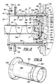
- the microwave deposition apparatus as seen in Figure 1, includes microwave propagating means 10, a vacuum chamber 12, and a window assembly 14.
- Microwave propagating means 10 is of known form and includes a microwave energy source 16 and an antennae probe 18.
- Source 16 may, for example, comprise a microwave frequency magnetron having an output frequency of, for example, 2.45 GHz.
- Vacuum chamber 12 also of known form, is adapted to deposit successive layers of material, preferably amorphous semiconductor alloy materials, onto suitable substrate members in response to microwave energy introduced into the interior of the vacuum chamber via the invention window assembly 14.
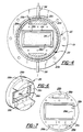
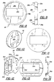
- the invention window assembly 14 includes a housing structure 19 constituted by a sleeve assembly including an outer sleeve 20 and an inner sleeve 22; a forward or primary window 24; a rearward or secondary window 26; a seal plate 28; a clamp plate 30; a support plate 32; and a waveguide tube 34.
- Outer sleeve 20 is cylindrical and is formed of a suitable metallic material.
- Outer sleeve 20 includes a main body axially extending tubular portion 20a, a radially outwardly extending flange portion 20b at the rearward end of the sleeve, and a radially inwardly extending flange portion 20c at the forward end of the sleeve.
- Sleeve main body portion 20a is received at its forward end in a suitable aperture 12a formed in a side wall 12b of vacuum chamber 12 so as to dispose forward flange 20c immediately inwardly of vacuum chamber side wall 12b.
- Inner sleeve 22 is formed of a suitable metallic material and includes a main body axially extending tubular portion 22a and a rearward flange portion 22b.
- a pair of diametrically opposed axially extending grooves 22c are formed in the outer circumferential surface of main body portion 22a.
- Axial grooves 22c communicate at their forward ends with a circumferential groove 22d proximate the forward end of main body portion 22a and groove 22d in turn communicates with the interior of the sleeve via a plurality of radial ports 22e.
- Inner sleeve 22 is sized to fit snugly and telescopically within outer sleeve 20 with grooves 22e and 22d coacting with the confronting inner surfaces of the main body portion 20a of the outer sleeve to define passages or channels between the inner and outer sleeves.
- a plurality of bolts 36 secure outer sleeve flange portion 20b to inner sleeve flange portion 22b to fixedly maintain the sleeves in their telescopic relation.
- Primary or forward window 24 is formed of a suitable dielectric material substantially transparent to microwave energy and has a generally cylindrical configuration. Window 24 is positioned proximate the forward ends of the inner and outer sleeves within opening 12a in vacuum chamber side wall 12b with the forward surface 24a of the window positioned at its peripheral edge against the rearward surface 20d of outer sleeve flange portion 20c and the rearward surface 24b of the window positioned at its peripheral edge against an annular shoulder 22f defined proximate the forward end of the main body portion 22a of the inner sleeve.
- the extreme forward edge of the inner sleeve is chamfered at 22g and acts to sealingly squeeze an annular sealing member 40 against the outer periphery of window 24 and against a rearwardly facing annular shoulder 20e defined by outer sleeve 20.
- Secondary or rear window 26 is also formed of a suitable dielectric material substantially transparent to microwave energy, has a substantially rectangular configuration, and has a thickness significantly less than the thickness of primary window 24.
- Seal plate 28 is formed of a suitable metallic material and has a generally cylindrical configuration sized to fit slidably within inner sleeve 22. Seal plate 28 includes a main body cylindrical portion 28a and a pair of diametrically opposed spacer portions 28b extending forwardly from the front surface 28c of the seal plate. A rectangular window opening 28d extends through main body portion 28a from rear surface 28e to front surface 28c and an annular rectangular seal groove 28f is provided in forward surface 28c in surrounding relation to window opening 28d. A further circular groove 28g is provided proximate the outer rearward edge of main body portion 28a.
- Seal plate 28 is positioned within inner sleeve 22 with the outer periphery of the plate contiguous with the inner periphery of main body portion 22a of the inner sleeve and with the forward surfaces 28h of the spacer portions 28b abutting against the rear surface 24b of primary window 24 to space the seal plate rearwardly from the primary window by a distance corresponding to the length of the spacer portions 28b.
- Clamp plate 30 is formed of a suitable metallic material and has a generally rectangular configuration.
- Plate 30 includes a main body portion 30a and upper and lower flange portions 30b connected to main body portion 30a by web portions 30c.
- a rectangular window opening 30d is formed in clamp plate main body portion 30a.
- Clamp plate 30 is secured to the front surface 28c of seal plate 28 by a plurality of bolts 42 with the secondary window 26 positioned within flange portions 30b so as to clamp the window between seal plate 28 and clamp plate 30.
- the front surface 26a of the window 26 is positioned against the rear surface of clamp plate main body portion 30a and the rear surface 26b of window 26 is positioned against the forward surface 28c of seal plate 28 with an annular elastomeric sealing member 44 positioned in seal plate annular groove 28f sealingly engaging the confronting outer annular portion of the rear surface 26b of window 26.
- Support plate 32 has a generally cylindrical configuration and fits slidably within inner sleeve main body portion 22a.
- Support plate 32 includes a central rectangular window opening 32a conforming in size and shape to the window opening 28d in seal plate 28.
- the forward surface 32b of support plate 32 is positioned against the rearward surface 28e of seal plate 28 by a plurality of bolts 46 passing through plate 32 for threaded engagement with threaded bores in the rear surface of the seal plate with an elastomeric seal 50 positioned in seal plate groove 28g to sealingly engage the inner periphery of inner sleeve 22.
- Waveguide 34 is formed of a suitable metallic material and has a rectangular cross-sectional configuration that is uniform throughout the length of the waveguide.
- Waveguide 34 includes a first portion 34a extending from microwave energy source 10 and a second portion 34b extending axially and centrally into inner sleeve 22 with its forward end portion 34c passing through aligned rectangular openings 32a and 28d in support plate 32 and seal plate 28, respectively, to abut the forward annular rectangular edge 34d of the waveguide tube against the rear surface 26b of secondary window 26.
- the inner peripheral surface 34e of the waveguide tube has a size and cross-sectional configuration precisely conforming to the size and cross-sectional configuration of window 30d of clamp plate 30 so that the surface defined by window 30d in effect forms a forward extension of the surface defined by the inner surface 34e of waveguide tube 34.
- Waveguide 34 is secured to sleeves 20/22 via an annular flange 52 welded to the outer periphery of the waveguide tube and secured by bolts 54 to the rear flange portion 22b of the inner sleeve.
- An entry tube 56 extends radially outwardly from main body portion 20a of outer sleeve 20 proximate rear flange 20b; a discharge tube 58 extends radially outwardly from main body portion 20a of outer sleeve 20 in generally diametrically opposed relation to tube 56; and an annular flange 60 is secured to the side wall 12b of the vacuum chamber 12, in surrounding relation to outer sleeve 20, by a plurality of bolts 62 with an annular sealing member 64 positioned in the crotch defined between flange 60, outer sleeve 20, and side wall 12b.
- tubes 56 and 58 coact with inner sleeve grooves 22c and 22d to define a path for delivering a cooling fluid, such as water, to the space 66 between the windows 24,26 and for removing fluid from the space so as to provide a continuous circulation of cooling fluid past the rearward surface of window 24.
- a cooling fluid such as water
- cooling fluid enters through tube 56, passes through bore 20f in outer sleeve 20 and into upper groove 22c, passes axially forwardly between the sleeves in upper groove 22c to circumferential groove 22d, passes radially inwardly through ports 22e into space 66, passes downwardly in space 66 past the rearward surface of window 24, passes radially downwardly through further ports 22e into the lower portion of circumferential groove 22d, passes axially rearwardly in lower groove 22c, and is then discharged through outer sleeve bore 20g and through discharge tube 58.
- the inner surface 34e of waveguide tube 34 forms a waveguide surface portion extending from energy source 10 to the rear surface 26b of window 26 and that the periphery of window opening 30d of clamp plate 30 forms a further waveguide surface portion constituting a forward extension of the waveguide surface portion defined by waveguide tube 34.
- window 26 extends radially outwardly beyond the waveguide surface defined by tube 34 and window opening 30d to define an annular outer window portion 26c outwardly of the waveguide surface and that the annular elastomeric seal 44 engages the rear surface of this annular outer portion 26c of the window 26 so that the sealing occurs at a location that is removed from the waveguide surface defined by the coaction of the inner periphery of waveguide tube 34 and window opening 30d.
- the microwave energy 70 employed in the invention apparatus typically has a wave length of approximately two inches so that the microwave energy moving down the waveguide surface defined by the waveguide tube is unaware of the 1/4 inch gap in the waveguide surface defined by the window 26. As a result, the microwave energy 70 moves with a constant size and form from the microwave energy source 10 to the forward end of the waveguide surface as defined by the forward end edge of window opening 30d.
- the microwave energy is maintained substantially intact in terms of size and shape from the microwave energy source to the rear surface of the primary window 24 so that the microwave energy passes through the window 24 and into the interior of the vacuum chamber substantially intact with respect to size and shape.
- the efficiency of the deposition/etching operation taking place within the vacuum chamber in response to the microwave energy is minimally deprecated by derogation in the form and size of the microwave's energy and the microwave energy is effectively precluded from access to the elastomeric seal 44 so that the problem of dealing with capacitive charges created at the seal by promiscuous microwave energy is substantially eliminated and so that, accordingly, an inexpensive elastomeric seal can be used in place of the expensive and exotic seals employed of necessity in the prior art devices.
- the invention microwave window assembly will thus be seen to allow the use of spaced double windows in the window assembly to avoid heating and failure of the primary window without derogating the size and shape of the microwave energy as it enters the vacuum chamber through the window and without necessitating the use of expensive and exotic seals to combat promiscuous microwave energy movement resulting from the spaced dual window construction.
Landscapes
- Drying Of Semiconductors (AREA)
- Constitution Of High-Frequency Heating (AREA)
- Plasma Technology (AREA)
Description
Claims (7)
- A microwave window assembly (14) for transmitting high power microwave energy from a microwave propagating means (10) into the interior of a chamber (12), and including first and second windows (24,26), formed of a dielectric material substantially transparent to microwave energy with the first window (24) adapted to be sealed in a wall (12b) of the chamber (12) and the second window (26) spaced rearwardly from said first window (24) in the direction of the microwave propagating means (10) to define a space (66) between said first and second windows (24,26) ; means for circulating a cooling fluid in the space (66) between said first (24) and second (26) windows; and a waveguide (34) for transmitting the microwave energy from the propagating means (10) to the window assembly (14), the waveguide (34) terminating proximate the rearward surface (26b) of the second window (26) in an end portion (34c) of substantially uniform cross-section which has a closed inner peripheral surface (34e), characterised in that a waveguide surface (30d) is provided within the space (66), the waveguide surface (30d) corresponding in size and cross-sectional configuration to said inner peripheral surface (34e), and being arranged so as to constitute a forward extension of the waveguide end portion (34c), said waveguide surface (30d) extending from the forward surface (26a) of the second window (26) and terminating at a location spaced rearwardly from the rearward surface (24b) of the first window (24), so as to not interfere with the circulation of cooling fluid between the windows (24,26).
- A microwave window assembly (14) as in claimed in claim 1, wherein said second window (26) extends radially outward beyond the exterior surface of said waveguide end portion(34c) so as to define an annular outer window portion (26c) extending outwardly of the waveguide (34) and annular sealing means (28) co-act with said annular window portion (26c) to seal the interior of the waveguide end portion (34c) from the circulating cooling fluid.
- A microwave window assembly (14) as claimed in claim 2, wherein said annular sealing means (28) includes a seal plate (28a).
- A microwave window assembly (14) as claimed in claim 3, further including a clamp plate (30) located within the space (66) and configured to engage said seal plate (28a) so as to retain said second window (26) therebetween, said clamp plate (30) having a window opening (30d) which defines said waveguide surface (30d).
- A microwave window assembly (14) as claimed in claim 3, wherein said second window (26) and said seal plate (28a) co-act to retain an elastomeric seal (44) therebetween such that microwave energy passing through the waveguide end portion (34c) is precluded from access to said seal (44).
- A microwave window assembly (14) as claimed in any preceding claim, further including a housing (19) which retains said first (24) and second (26) windows and at least a part of said waveguide end portion (34c), said housing (19) including an outer sleeve (20) and an inner sleeve (22) concentric therewith, and wherein said means for circulating cooling fluid is also operative to circulate a cooling fluid between said sleeves (20,22).
- A microwave window assembly (14) as claimed in claim 6, wherein said housing 19 further includes an annular flange (52) which secures said waveguide end portion (34c) to said inner (22) and outer (20) sleeves.
Applications Claiming Priority (3)
| Application Number | Priority Date | Filing Date | Title |
|---|---|---|---|
| US07/800,160 US5200722A (en) | 1991-11-27 | 1991-11-27 | Microwave window assembly |
| US800160 | 1991-11-27 | ||
| PCT/US1992/009567 WO1993011576A1 (en) | 1991-11-27 | 1992-11-06 | Microwave window assembly |
Publications (3)
| Publication Number | Publication Date |
|---|---|
| EP0614575A1 EP0614575A1 (en) | 1994-09-14 |
| EP0614575A4 EP0614575A4 (en) | 1995-03-08 |
| EP0614575B1 true EP0614575B1 (en) | 1999-01-13 |
Family
ID=25177635
Family Applications (1)
| Application Number | Title | Priority Date | Filing Date |
|---|---|---|---|
| EP92924328A Expired - Lifetime EP0614575B1 (en) | 1991-11-27 | 1992-11-06 | Microwave window assembly |
Country Status (5)
| Country | Link |
|---|---|
| US (1) | US5200722A (en) |
| EP (1) | EP0614575B1 (en) |
| AU (1) | AU3067892A (en) |
| DE (1) | DE69228196D1 (en) |
| WO (1) | WO1993011576A1 (en) |
Families Citing this family (15)
| Publication number | Priority date | Publication date | Assignee | Title |
|---|---|---|---|---|
| US5495218A (en) * | 1994-04-20 | 1996-02-27 | Thermo Instrument Controls Inc. | Microwave waveguide seal assembly |
| US6362449B1 (en) | 1998-08-12 | 2002-03-26 | Massachusetts Institute Of Technology | Very high power microwave-induced plasma |
| US6325391B1 (en) | 1998-11-12 | 2001-12-04 | Rosemount Inc. | PTFE window seal with EMI shielding |
| US6502529B2 (en) | 1999-05-27 | 2003-01-07 | Applied Materials Inc. | Chamber having improved gas energizer and method |
| RU2185679C1 (en) * | 2001-07-12 | 2002-07-20 | Открытое акционерное общество "Корпорация "Фазотрон-Научно-исследовательский институт радиостроения" | Method for producing energy input/output of parison-marker microwave device |
| RU2260881C2 (en) * | 2003-08-12 | 2005-09-20 | Федеральное государственное унитарное предприятие "Научно-производственное предприятие "Исток" | Microwave and ehf energy output window for electronic devices |
| RU2285313C2 (en) * | 2004-04-26 | 2006-10-10 | Федеральное государственное унитарное предприятие "Научно-производственное предприятие "Исток" (ФГУП НПП "Исток") | Method for producing microwave and extremely high-frequency energy output window for electronic devices |
| GB0426394D0 (en) | 2004-12-01 | 2005-01-05 | Health Prot Agency | Fusion proteins |
| US20060223923A1 (en) | 2005-02-07 | 2006-10-05 | Serge Cavalli | Thermoplastic vulcanisate blend |
| CN100458865C (en) * | 2006-10-18 | 2009-02-04 | 中国科学院等离子体物理研究所 | A microwave breakdown protection method in a waveguide |
| RU2487445C1 (en) * | 2011-12-28 | 2013-07-10 | Закрытое акционерное общество "Научно-производственный центр "Алмаз-Фазотрон" | Method of shf filter fabrication |
| US9715183B2 (en) * | 2012-02-23 | 2017-07-25 | Asml Netherlands B.V. | Device, lithographic apparatus, method for guiding radiation and device manufacturing method |
| CN106369933A (en) * | 2016-11-09 | 2017-02-01 | 佛山市建春友金属科技有限公司 | Stainless steel cooling stick |
| RU2725698C1 (en) * | 2019-12-10 | 2020-07-03 | Акционерное общество "Научно-производственное предприятие "Исток" имени А.И. Шокина" (АО "НПП "Исток" им. Шокина") | Method of producing shf energy output window |
| CN116259945B (en) * | 2022-09-08 | 2024-04-23 | 电子科技大学 | High power capacity TM01/TE11Mode vacuum pumping waveguide |
Family Cites Families (6)
| Publication number | Priority date | Publication date | Assignee | Title |
|---|---|---|---|---|
| US4286240A (en) * | 1979-12-03 | 1981-08-25 | Varian Associates, Inc. | Circular electric mode microwave window |
| DE3028461A1 (en) * | 1980-07-26 | 1982-04-08 | Philips Patentverwaltung Gmbh, 2000 Hamburg | HIGH-STRENGTH HF WINDOW, ESPECIALLY FOR LARGE KLYSTRONS |
| US4371854A (en) * | 1981-04-27 | 1983-02-01 | Varian Associates, Inc. | Broadband high-power microwave window assembly |
| US4620170A (en) * | 1984-12-19 | 1986-10-28 | Varian Associates, Inc. | Means for liquid cooling a microwave window |
| US4729341A (en) * | 1985-09-18 | 1988-03-08 | Energy Conversion Devices, Inc. | Method and apparatus for making electrophotographic devices |
| US4931756A (en) * | 1988-04-08 | 1990-06-05 | Energy Conversion Devices, Inc. | High power microwave transmissive window assembly |
-
1991
- 1991-11-27 US US07/800,160 patent/US5200722A/en not_active Expired - Lifetime
-
1992
- 1992-11-06 EP EP92924328A patent/EP0614575B1/en not_active Expired - Lifetime
- 1992-11-06 WO PCT/US1992/009567 patent/WO1993011576A1/en not_active Ceased
- 1992-11-06 AU AU30678/92A patent/AU3067892A/en not_active Abandoned
- 1992-11-06 DE DE69228196T patent/DE69228196D1/en not_active Expired - Lifetime
Also Published As
| Publication number | Publication date |
|---|---|
| WO1993011576A1 (en) | 1993-06-10 |
| EP0614575A4 (en) | 1995-03-08 |
| US5200722A (en) | 1993-04-06 |
| EP0614575A1 (en) | 1994-09-14 |
| DE69228196D1 (en) | 1999-02-25 |
| AU3067892A (en) | 1993-06-28 |
Similar Documents
| Publication | Publication Date | Title |
|---|---|---|
| US5200722A (en) | Microwave window assembly | |
| US3096462A (en) | High power electron discharge device | |
| US4968489A (en) | UV lamp enclosure sleeve | |
| US4851788A (en) | Mode suppressors for whispering gallery gyrotron | |
| US5961851A (en) | Microwave plasma discharge device | |
| EP0737256B1 (en) | Microwave plasma reactor | |
| US5877471A (en) | Plasma torch having a cooled shield assembly | |
| CN106997838B (en) | It is a kind of that interaction device is extended using the millimeter wave of coaxial resonant cavity and many electrons’ system | |
| KR100491214B1 (en) | High power microwave plasma applicator | |
| GB2243943A (en) | Electron beam tube with input cavity | |
| GB2082844A (en) | Microwave window assembly | |
| JPH04332433A (en) | Quasi-optical constituent for emitting microwave | |
| EP2594660B1 (en) | An apparatus for performing a plasma chemical vapour deposition process | |
| US4027255A (en) | Fast recovery time receiver protector for radars | |
| US3305742A (en) | High frequency electron discharge device and cooling means therefor | |
| US4129834A (en) | Resonant cavity magnetron with choke structure for reducing harmonics in output system | |
| JPH04262601A (en) | Microwave joint device | |
| CA2181101A1 (en) | Linear electron beam tube arrangements | |
| KR20010075494A (en) | Method and apparatus for plasma processing | |
| US3325671A (en) | Klystron device having fluid cooled tunable cavities and output window mode suppression means | |
| US6369493B1 (en) | Microwave plasma applicator having a thermal transfer medium between a plasma containing tube and a cooling jacket | |
| US2929955A (en) | Cavity resonator for klystron tube | |
| US3434076A (en) | Waveguide window having circulating fluid of critical loss tangent for dampening unwanted mode | |
| US3526798A (en) | X-ray shield structure for liquid cooled electron beam collectors and tubes using same | |
| US5469024A (en) | Leaky wall filter for use in extended interaction klystron |
Legal Events
| Date | Code | Title | Description |
|---|---|---|---|
| PUAI | Public reference made under article 153(3) epc to a published international application that has entered the european phase |
Free format text: ORIGINAL CODE: 0009012 |
|
| 17P | Request for examination filed |
Effective date: 19940517 |
|
| AK | Designated contracting states |
Kind code of ref document: A1 Designated state(s): DE ES FR GB IT |
|
| A4 | Supplementary search report drawn up and despatched |
Effective date: 19950118 |
|
| AK | Designated contracting states |
Kind code of ref document: A4 Designated state(s): DE ES FR GB IT |
|
| 17Q | First examination report despatched |
Effective date: 19970214 |
|
| GRAG | Despatch of communication of intention to grant |
Free format text: ORIGINAL CODE: EPIDOS AGRA |
|
| GRAG | Despatch of communication of intention to grant |
Free format text: ORIGINAL CODE: EPIDOS AGRA |
|
| GRAH | Despatch of communication of intention to grant a patent |
Free format text: ORIGINAL CODE: EPIDOS IGRA |
|
| GRAH | Despatch of communication of intention to grant a patent |
Free format text: ORIGINAL CODE: EPIDOS IGRA |
|
| GRAA | (expected) grant |
Free format text: ORIGINAL CODE: 0009210 |
|
| AK | Designated contracting states |
Kind code of ref document: B1 Designated state(s): DE ES FR GB IT |
|
| PG25 | Lapsed in a contracting state [announced via postgrant information from national office to epo] |
Ref country code: FR Free format text: LAPSE BECAUSE OF FAILURE TO SUBMIT A TRANSLATION OF THE DESCRIPTION OR TO PAY THE FEE WITHIN THE PRESCRIBED TIME-LIMIT Effective date: 19990113 Ref country code: ES Free format text: THE PATENT HAS BEEN ANNULLED BY A DECISION OF A NATIONAL AUTHORITY Effective date: 19990113 |
|
| REF | Corresponds to: |
Ref document number: 69228196 Country of ref document: DE Date of ref document: 19990225 |
|
| ITF | It: translation for a ep patent filed | ||
| PG25 | Lapsed in a contracting state [announced via postgrant information from national office to epo] |
Ref country code: DE Free format text: LAPSE BECAUSE OF FAILURE TO SUBMIT A TRANSLATION OF THE DESCRIPTION OR TO PAY THE FEE WITHIN THE PRESCRIBED TIME-LIMIT Effective date: 19990414 |
|
| EN | Fr: translation not filed | ||
| PG25 | Lapsed in a contracting state [announced via postgrant information from national office to epo] |
Ref country code: GB Free format text: LAPSE BECAUSE OF NON-PAYMENT OF DUE FEES Effective date: 19991106 |
|
| PLBE | No opposition filed within time limit |
Free format text: ORIGINAL CODE: 0009261 |
|
| STAA | Information on the status of an ep patent application or granted ep patent |
Free format text: STATUS: NO OPPOSITION FILED WITHIN TIME LIMIT |
|
| 26N | No opposition filed | ||
| GBPC | Gb: european patent ceased through non-payment of renewal fee |
Effective date: 19991106 |
|
| PGFP | Annual fee paid to national office [announced via postgrant information from national office to epo] |
Ref country code: IT Payment date: 20101124 Year of fee payment: 19 |