EP0614436B1 - Modular inflated supporting structure - Google Patents
Modular inflated supporting structure Download PDFInfo
- Publication number
- EP0614436B1 EP0614436B1 EP92924526A EP92924526A EP0614436B1 EP 0614436 B1 EP0614436 B1 EP 0614436B1 EP 92924526 A EP92924526 A EP 92924526A EP 92924526 A EP92924526 A EP 92924526A EP 0614436 B1 EP0614436 B1 EP 0614436B1
- Authority
- EP
- European Patent Office
- Prior art keywords
- modules
- supporting structure
- product
- module
- modular supporting
- Prior art date
- Legal status (The legal status is an assumption and is not a legal conclusion. Google has not performed a legal analysis and makes no representation as to the accuracy of the status listed.)
- Expired - Lifetime
Links
Images


Classifications
-
- B—PERFORMING OPERATIONS; TRANSPORTING
- B65—CONVEYING; PACKING; STORING; HANDLING THIN OR FILAMENTARY MATERIAL
- B65D—CONTAINERS FOR STORAGE OR TRANSPORT OF ARTICLES OR MATERIALS, e.g. BAGS, BARRELS, BOTTLES, BOXES, CANS, CARTONS, CRATES, DRUMS, JARS, TANKS, HOPPERS, FORWARDING CONTAINERS; ACCESSORIES, CLOSURES, OR FITTINGS THEREFOR; PACKAGING ELEMENTS; PACKAGES
- B65D81/00—Containers, packaging elements, or packages, for contents presenting particular transport or storage problems, or adapted to be used for non-packaging purposes after removal of contents
- B65D81/02—Containers, packaging elements, or packages, for contents presenting particular transport or storage problems, or adapted to be used for non-packaging purposes after removal of contents specially adapted to protect contents from mechanical damage
- B65D81/05—Containers, packaging elements, or packages, for contents presenting particular transport or storage problems, or adapted to be used for non-packaging purposes after removal of contents specially adapted to protect contents from mechanical damage maintaining contents at spaced relation from package walls, or from other contents
- B65D81/053—Corner, edge or end protectors
- B65D81/055—Protectors contacting three surfaces of the packaged article, e.g. three-sided edge protectors
- B65D81/056—Protectors contacting three surfaces of the packaged article, e.g. three-sided edge protectors the surfaces being generally perpendicular to each other, e.g. three-sided corner protectors
-
- B—PERFORMING OPERATIONS; TRANSPORTING
- B65—CONVEYING; PACKING; STORING; HANDLING THIN OR FILAMENTARY MATERIAL
- B65D—CONTAINERS FOR STORAGE OR TRANSPORT OF ARTICLES OR MATERIALS, e.g. BAGS, BARRELS, BOTTLES, BOXES, CANS, CARTONS, CRATES, DRUMS, JARS, TANKS, HOPPERS, FORWARDING CONTAINERS; ACCESSORIES, CLOSURES, OR FITTINGS THEREFOR; PACKAGING ELEMENTS; PACKAGES
- B65D81/00—Containers, packaging elements, or packages, for contents presenting particular transport or storage problems, or adapted to be used for non-packaging purposes after removal of contents
- B65D81/02—Containers, packaging elements, or packages, for contents presenting particular transport or storage problems, or adapted to be used for non-packaging purposes after removal of contents specially adapted to protect contents from mechanical damage
- B65D81/05—Containers, packaging elements, or packages, for contents presenting particular transport or storage problems, or adapted to be used for non-packaging purposes after removal of contents specially adapted to protect contents from mechanical damage maintaining contents at spaced relation from package walls, or from other contents
- B65D81/051—Containers, packaging elements, or packages, for contents presenting particular transport or storage problems, or adapted to be used for non-packaging purposes after removal of contents specially adapted to protect contents from mechanical damage maintaining contents at spaced relation from package walls, or from other contents using pillow-like elements filled with cushioning material, e.g. elastic foam, fabric
- B65D81/052—Containers, packaging elements, or packages, for contents presenting particular transport or storage problems, or adapted to be used for non-packaging purposes after removal of contents specially adapted to protect contents from mechanical damage maintaining contents at spaced relation from package walls, or from other contents using pillow-like elements filled with cushioning material, e.g. elastic foam, fabric filled with fluid, e.g. inflatable elements
-
- B—PERFORMING OPERATIONS; TRANSPORTING
- B65—CONVEYING; PACKING; STORING; HANDLING THIN OR FILAMENTARY MATERIAL
- B65D—CONTAINERS FOR STORAGE OR TRANSPORT OF ARTICLES OR MATERIALS, e.g. BAGS, BARRELS, BOTTLES, BOXES, CANS, CARTONS, CRATES, DRUMS, JARS, TANKS, HOPPERS, FORWARDING CONTAINERS; ACCESSORIES, CLOSURES, OR FITTINGS THEREFOR; PACKAGING ELEMENTS; PACKAGES
- B65D2581/00—Containers, packaging elements, or packages, for contents presenting particular transport or storage problems, or adapted to be used for non-packaging purposes after removal of contents
- B65D2581/02—Containers, packaging elements, or packages, for contents presenting particular transport or storage problems, or adapted to be used for non-packaging purposes after removal of contents specially adapted to protect contents from mechanical damage
- B65D2581/05—Containers, packaging elements, or packages, for contents presenting particular transport or storage problems, or adapted to be used for non-packaging purposes after removal of contents specially adapted to protect contents from mechanical damage maintaining contents at spaced relation from package walls, or from other contents
- B65D2581/051—Details of packaging elements for maintaining contents at spaced relation from package walls, or from other contents
- B65D2581/052—Materials
- B65D2581/055—Plastic in general, e.g. foamed plastic, molded plastic, extruded plastic
-
- B—PERFORMING OPERATIONS; TRANSPORTING
- B65—CONVEYING; PACKING; STORING; HANDLING THIN OR FILAMENTARY MATERIAL
- B65D—CONTAINERS FOR STORAGE OR TRANSPORT OF ARTICLES OR MATERIALS, e.g. BAGS, BARRELS, BOTTLES, BOXES, CANS, CARTONS, CRATES, DRUMS, JARS, TANKS, HOPPERS, FORWARDING CONTAINERS; ACCESSORIES, CLOSURES, OR FITTINGS THEREFOR; PACKAGING ELEMENTS; PACKAGES
- B65D2581/00—Containers, packaging elements, or packages, for contents presenting particular transport or storage problems, or adapted to be used for non-packaging purposes after removal of contents
- B65D2581/02—Containers, packaging elements, or packages, for contents presenting particular transport or storage problems, or adapted to be used for non-packaging purposes after removal of contents specially adapted to protect contents from mechanical damage
- B65D2581/05—Containers, packaging elements, or packages, for contents presenting particular transport or storage problems, or adapted to be used for non-packaging purposes after removal of contents specially adapted to protect contents from mechanical damage maintaining contents at spaced relation from package walls, or from other contents
- B65D2581/051—Details of packaging elements for maintaining contents at spaced relation from package walls, or from other contents
- B65D2581/058—Edge or corner protectors connected to each other by separate elements
Definitions
- This invention relates to packing elements and more particularly relates to elements that are used to protect a product packed in a container such as a box.
- the container and the product therein are each of a predetermined size and shape.
- the packing material displaces the product from the cardboard box around all sides of the product so that almost any impact on the cardboard box will not directly reach the product.
- the packing material preferably keeps the product in a fixed relation with respect to the cardboard box so that the product does not move around within the cardboard box. In order to keep the product in fixed relation within the cardboard box, it is necessary that the product fit snugly within the packing material and also that the packing material fit snugly within the cardboard box.
- Two types of forces may be encountered by a packed product during shipping and storage. Firstly, there is movement of the cardboard box, which may be quite sudden or severe. This sudden or severe movement would cause the cardboard box to experience related accelerative and decelerative forces. Correspondingly, the product inside must move along with the cardboard box, and if there is no cushioning between the product and the cardboard box, the product would experience roughly the same accelerative and decelerative forces experienced by the cardboard box. Secondly, there are impact forces that can occur as a result of a sudden impact with the cardboard box by another object. Again, the accelerative forces are transmitted through the box to the product and must be cushioned in order to protect the product from potential damage.
- US-A-4,905,835, issued to PIVERT et al discloses an Inflatable Cushion Packaging that comprises a flexible inflatable structure having three separate inflatable cushions that are in fluid communication with one another. Two of these structures are used to protect the product in a box. One structure forms the bottom and two opposed sides and the other structure forms the top and the other two opposed sides. This packaging product is inflated to whatever size is necessary, within limits, to snugly pack the product within the box. It is not of a fixed size and therefore is not product specific.
- US-A-3,889,743, issued to PRESNICK discloses Inflatable Insulation for packaging comprising a flexible, collapsible bag structure.
- the bag structure comprises a pair of flexible thermoplastic bags one inside the other.
- the bags are inflated, at least partially, to create a "dead air space" that provides physical and thermal insulation for packing.
- the Inflatable Insulation is placed in a box and the product is then placed within the packaging and the packaging is then inflated. This insulation can accommodate various sizes of products and therefore is not product specific.
- US-A-4,551,379 issued to KERR discloses an Inflatable Packaging Material that is formed from a pair of juxtaposed sheets as a plurality of continuous passages between the two sheets with each of the passages being in limited fluid communication with adjacent passages.
- the passages are inflatable to provide a shock absorbing facility.
- the inflatable packaging material disclosed in this patent can be used for packing various sizes of products into various sizes of containers and therefore is not product specific.
- US-A-5,030,501 issued to COLVIN et al discloses a Cushioning Structure to be used as a packing material to protect packaged goods.
- the cushioning structure comprises a sheet of material having a plurality of cell structures bonded and sealed thereto.
- the cell structures are in fluid communication with one another but overall are sealed from the ambient surroundings. Restricted air flow between the cells provides the structure with its cushioning properties.
- GB-A-2 246 767 shows a protective packaging module where four corner pieces are connected by a connecting sheet of cardboard.
- Each corner piece has two protective side elements of foamed polystyrene that are mounted on a cardboard carrier, with the carrier being scored so that it can be bent to bring the two elements against two sides of the cabinet being protected at the corner thereof. None of the corner pieces is inflated, and an extra connecting sheet of cardboard is required to maintain the physical separation of the corner elements.
- the present invention provides a modular supporting structure for positioning and supporting a product within an outer packing container such as a cardboard box.
- the modular supporting structure of the present invention is made up of a plurality of modules. These modules are separately inflatable one from the other.
- the modules may be formed as one continuous piece of material, in which case inflation of the module occurs during the blow molding manufacturing process.
- the module may include a removable cap that is used to provide access to the interior of the module for purposes of inflation and deflation.
- the modules are often deflated to a relatively uninflated reduced size -- as compared to their full blow molded size. The modules are then kept relatively uninflated until they are ready to be used. Inflation of the modules is typically done shortly before the modules are in place within the packing container.
- the modules are preferably made of polyethylene plastic and are blow moulded to a finished shape.
- the modules can also be made of other plastic resins such as polypropylene and rubber.
- the material is flexible, however, and the module can be collapsed to a fairly flat configuration. When the module is inflated, it takes on its full size and shape.
- the shape and thickness of the module are predetermined by the size and shape of the product that is being packed and the size and shape of the outer packing container.
- the overall size of each module can vary for any given product and outer packing container, depending on how much of the product is to be in direct contact with the modules.
- the modules must of course interconnect one with another in order to form a modular supporting structure.
- This interconnection is accomplished by means of a connecting portion that is typically in the form of a flange.
- the flange contains a pair of protruding locking members and at least a pair of co-operating openings therein. The locking members of one flange are received and retained by the cooperating openings of a flange of an adjacent module, thus forming a snap-type interconnecting means.
- the modules of the present invention are composed of a plurality of compartments that are interconnected by a restrictive air passage that limits the passage of air between the compartments, thus providing for a cushioning effect through the damping of air flow between the compartments.
- a restrictive air passage is not necessary; however, it does improve the effectiveness of the cushioning of the modular supporting structure.
- the present invention is directed to a modular supporting structure for positioning and supporting a product within an outer packing container, wherein the product to be supported has predetermined external dimensions, and the outer packing container forms a chamber of predetermined internal dimensions.
- the supporting structure comprises a plurality of modules that are interconnected one to another, wherein each module has an exterior surface that is generally shaped and sized so as to correspond to a portion of the predetermined internal dimensions of the outer packing container; and each module has an inwardly directed receiving surface that is generally shaped and sized so as to correspond to a portion of the predetermined external dimensions of the product to be supported.
- the modular supporting structure has a predetermined shaped product-receiving socket which is defined by the inwardly directed surfaces of the plurality of modules. All of the above is essentially as also described in GB-A-2 246 767 noted above.
- the present invention is characterized by the fact that each module in turn comprises an at least partially inflated bladder and a connecting portion that is attached to the bladder for each respective module.
- Each of the bladder has at least a first compartment for receiving and retaining an inflating gas.
- the plurality of modules is separably connected one to another by way of the connecting portions, so that together they form the modular supporting structure. Also, each of the modules is maintained physically separated from the others by the connecting portions being interconnected one to another, so that each of the modules acts independently of each other in terms of the load supported by each.
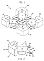
- FIG. 1 shows the modular supporting structure 20 of the present invention in a constructed form, and comprised of four modules 22.
- each of the modules 22 is identical one to another.
- the resulting modular supporting structure is essentially a cruciform formation with a square product receiving socket 24 --shown in dashed outline -- formed by the relative positions of the four modules. Interconnection of the modules into a modular supporting structure and subsequent functioning of the modular supporting structure will be discussed in greater detail subsequently.
- the module 22 comprises a first compartment 30, a second compartment 32, and a flange 34.
- the first and second compartments together form an air bladder that is inflated.
- the preferred and most often used inflation medium is air.
- Other inflation media such as sulphur hexafluoride may also be used, if desired.
- the first compartment 30 has a first exterior surface 40 that includes three separate outer faces. These three separate outer faces contact the packing container in one corner thereof with each of the three separate outer faces contacting a separate inner face -- either the top, bottom or one of the sides -- of the packing container.
- the second compartment 32 also has an exterior surface 42 at the bottom thereof for contacting a portion of one inner face of the packing container.
- the first and second compartments 30, 32 together also have an inwardly directed surface 44, which is comprised of three separate portions. In the preferred embodiment, these three separate portions are at right angles to one another and form a corner shape that is adapted to receive a similarly shaped corner of a product. There is also an concavely shaped elongated recess 46 in the first compartment 30. This recess 46 receives a portion of one of the three corners --and the vertex of these three corners of the product being supported by the modular supporting structure 20. The corner and vertex are thereby precluded from cutting into the first compartment 30.
- the first compartment 30 and the second compartment 32 are connected so as to be in fluid communication with one another by a virtue of restrictive air passage 48.
- the restrictive air passage 48 allows the first and second compartments 30, 32 to be in limited fluid communication with one another by restricting the amount of air that can pass from one compartment to another over a given period of time.
- the purpose for the two compartments being in fluid communication with one another in this restricted manner is to permit either compartment to deflate slightly if it experiences a sudden heavier load on it or sudden impact force on it, thus providing a damping effect.
- the diameter of the passage 48 is chosen so as to allow air to pass between the compartments 30, 32 quickly enough to allow either compartment to deform somewhat in the event of a sudden impact or increase in weight on it, but not so quickly as to allow either compartment to virtually collapse, thereby providing insufficient cushioning.
- a two-way valve or two counterfacing one-way valves could conceivably be used to control the airflow between the first and second compartments 30, 32.
- the first and second compartments 30, 32 are inflated through an inflation tube 50 which is in fluid communication with the second compartment 32 and is also selectably in fluid communication with the exterior of the module 22 at its end 52.
- a cap 54 is placed over the end 52 of the inflation tube 50 to preclude air within the first and second compartments 30, 32 from escaping through inflation tube 50.
- the cap 54 is also used to allow the air bladder to be deflated after the module 22 has been manufactured or after it has been used, and also to allow the air bladder to be refilled and resealed. Indeed, the module 22 may be reused several times and may be deflated and re-inflated each time. The module would of course be ultimately recyclable.
- a valve may be used to control air flow through the end 52 of the inflation tube 50.
- the inflation tube 50 could have a permanently closed end in the form of a snip-off nipple.
- a module of this configuration would therefore be formed as one continuous piece of material, in which case inflation of the module occurs during the blow molding process. The module would remain in this fully inflated condition until the snip-off nipple is removed.
- the flange 34 extends outwardly from the second compartment 32 and is generally -- at least to some degree -- in the same plane as the portion of the inwardly directed surface 44 on the second compartment 32.
- the flange 34 includes a first portion 56 and a second portion 58.
- the first portion 56 is located slightly above the second portion 58.
- the top surface 60 of the second portion 58 is approximately at the same level as the bottom surface 62 of the first portion 58.
- This combination of locking members 64 and cooperating openings 66 basically constitute a snap type fastener.
- Figure 6 shows a cutaway view of a single locking member that has been received and retained by a cooperating opening 66
- the diameter of the locking member 64 is slightly greater than the diameter of the cooperating opening 66, which causes the locking member 64 to be retained within the cooperating opening 66.
- FIG. 1 shows four modules 22 interconnected with one another.
- the module marked A has its first portion 56A of the flange 34A overlapped overtop of the second portion 58B of the adjacent module marked B and its second portion 58A overlapped underneath the first portion 56D of the module marked D .
- the module marked B has its first portion 56B of the flange 34B overlapped overtop the second portion 58C of the flange 34C of the module marked C and its second portion 58B overlapped underneath the first portion 56C of the module marked C .
- the flange 34C of the module marked C overlaps with the flanges of the adjacent modules marked B and D and the flange 34D of the module marked D overlaps with the flanges of the adjacent modules marked B and D .
- the four modules are interconnected one with the other in an interleaved manner thus forming the modular supporting structure of the present invention. It can be seen that a square product receiving socket 24 is formed by such interconnection of these four identical modules.
- the modular supporting structure of the present invention is commonly used in the following manner.
- a packing container typically a cardboard box, is placed ready to receive packing materials and a product therein, with the top of the box being open.
- a modular supporting structure typically made up of four modules 22 -- is placed at the bottom of the box with the product receiving socket 24 facing upwardly.
- the product to be packed is then placed in to the box and seated in the product receiving socket 24.
- the modules 22 are of a size such that the product receiving socket is essentially the same size as the particular product being retained therein. Thus, the product is held reasonably snugly.
- Another modular supporting structure is then placed on top of the product. This second modular supporting structure must of course be oriented with the product receiving socket 24 facing downwardly.
- the cardboard box can then be closed.
- FIG. 7 shows an alternative embodiment, wherein the module 70 has an extended flange 72.
- the extended flange 72 has two pairs of protruding locking members 74 and also two pairs of cooperating openings 76. Each pair of protruding locking members 74 can be received and retained by either pair of cooperating openings 76.
- the size of the modular supporting structure that is formed from interconnecting four such modules is not limited to just one size.
- FIG 8 shows an alternative embodiment of the present invention, wherein a module 80 has two locking members 82 and three cooperating openings 84.
- the two locking members 82 can be placed either in the two cooperating openings marked A and B or the two co-operating openings 84 marked B and C .
- co-operating openings 84 By having this configuration of co-operating openings 84, it is possible to form more than one size of modular supporting structure. Further, it is possible to form a modular supporting structure that has a rectangularly shaped product receiving structure. It is of course also possible to include more than three co-operating openings 84, if desired.
- Figure 9 shows a further alternative embodiment of the invention.
- module 90 having a first compartment 91 and a second compartment 92 as does the module in the preferred embodiment.
- Extending outwardly from the first compartment 91 in a first direction is a flange 93 and extending outwardly from the first compartment 91 in a second direction is second flange 94.
- the first flange 93 has a series of collinearly aligned protruding locking members 95 and the second flange 94 has a plurality of collinearly aligned co-operating openings 96 that are adapted to receive and retain the locking members 95.
- This embodiment of module can be used to form either square or rectangular modular supporting structures with the number of co-operating openings 96 determining how many sizes of modular supporting structure can be formed. Either square or rectangular modular supporting structures can be formed. It is also possible to have the first and second flanges 93, 94 extending outwardly from the second compartment 92 in a similar manner to that described above.
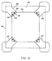
- FIG. 10 shows a still alternative embodiment of the present invention.
- a modular supporting structure 100 has been formed from four modules 102, which are interconnected by an interconnecting member 104.
- the interconnecting member 104 is preferably a piece of plastic, either solid or with openings cut in it for weight reduction purposes, that spans between the four modules 102.
- the modules 102 connect to the interconnecting member 104 in a manner similar to that disclosed above.
- the module 102 has protruding locking members 106 that protrude upwardly from the module 102.
- the interconnecting member 104 has a pair of cooperating openings 108 that receive and retain the protruding locking members 106 of the module 102.
- each module is fastened in fixed relation to the interconnecting member 104 which thereby keeps all four of the modules 102 in a fixed relation to one another.
- the modules 102 form a product receiving socket 109 that is of a particular size and shape as determined by the size and shape of the interconnecting member 104.
- Advantageous features of this particular alternative embodiment are that virtually any size and shape of product can be accommodated by using the appropriate size and shape of interconnecting member 104. Further, only one size and shape of module 102 is specifically required to form any size of square or rectangular product receiving sockets 109.
- the module 110 has a slot 111 horizontally disposed in the second compartment 112.
- An interconnecting member 113 is slid into the slot 111.
- a protrusion 114 on the bottom surface 115 of the slot 111 enters an aperture 116 in the interconnecting member 113.
- the interconnecting member 113 is retained in the slot 111 by the protrusion 114 in the aperture 116.
- the inwardly directed surface of a module could be curved in order to accommodate a round product, and the interconnecting member could be any shape as required.
Abstract
Description
- This invention relates to packing elements and more particularly relates to elements that are used to protect a product packed in a container such as a box. Specifically, the container and the product therein are each of a predetermined size and shape.
- Many products that are manufactured and ultimately sold for and used by an end user -- whether it be a company or an individual -- must be shipped at least once from where the product is produced to where the product is stored, consumed or used. In actuality, a product may be shipped several times, such as from the manufacturer to the distributor, to the warehouse, then to a retail store and ultimately to an end user. It is of course necessary that the product be protected during this time of shipping and storage so that it ultimately reaches the end user in an unharmed condition.
- A very widely used -- and indeed almost universally used -- packaging system for protecting products that could be easily damaged during shipping and storage -- typically items such as electrical or electronic appliances -- consists of a cardboard box with packing material interposed between the product and the inner walls of the cardboard box. The packing material displaces the product from the cardboard box around all sides of the product so that almost any impact on the cardboard box will not directly reach the product. Further, the packing material preferably keeps the product in a fixed relation with respect to the cardboard box so that the product does not move around within the cardboard box. In order to keep the product in fixed relation within the cardboard box, it is necessary that the product fit snugly within the packing material and also that the packing material fit snugly within the cardboard box.
- Two types of forces may be encountered by a packed product during shipping and storage. Firstly, there is movement of the cardboard box, which may be quite sudden or severe. This sudden or severe movement would cause the cardboard box to experience related accelerative and decelerative forces. Correspondingly, the product inside must move along with the cardboard box, and if there is no cushioning between the product and the cardboard box, the product would experience roughly the same accelerative and decelerative forces experienced by the cardboard box. Secondly, there are impact forces that can occur as a result of a sudden impact with the cardboard box by another object. Again, the accelerative forces are transmitted through the box to the product and must be cushioned in order to protect the product from potential damage.
- In order that forces experienced under various shipping and storage conditions are not transmitted to the product, it is necessary to have some sort of packing material that will deform to some degree in order to absorb the impact forces slowly and evenly over a period of time. This will spread out the absorption of the energy of the impact forces such that the full impact forces will not be transmitted to the product. Resultingly, a smaller force will be transmitted over a longer period of time. The product will not experience as great a force, and therefore will be less likely to be damaged.
- US-A-4,905,835, issued to PIVERT et al discloses an Inflatable Cushion Packaging that comprises a flexible inflatable structure having three separate inflatable cushions that are in fluid communication with one another. Two of these structures are used to protect the product in a box. One structure forms the bottom and two opposed sides and the other structure forms the top and the other two opposed sides. This packaging product is inflated to whatever size is necessary, within limits, to snugly pack the product within the box. It is not of a fixed size and therefore is not product specific.
- US-A-3,889,743, issued to PRESNICK discloses Inflatable Insulation for packaging comprising a flexible, collapsible bag structure. The bag structure comprises a pair of flexible thermoplastic bags one inside the other. The bags are inflated, at least partially, to create a "dead air space" that provides physical and thermal insulation for packing. In use, the Inflatable Insulation is placed in a box and the product is then placed within the packaging and the packaging is then inflated. This insulation can accommodate various sizes of products and therefore is not product specific.
- US-A-4,551,379, issued to KERR discloses an Inflatable Packaging Material that is formed from a pair of juxtaposed sheets as a plurality of continuous passages between the two sheets with each of the passages being in limited fluid communication with adjacent passages. The passages are inflatable to provide a shock absorbing facility. The inflatable packaging material disclosed in this patent can be used for packing various sizes of products into various sizes of containers and therefore is not product specific.
- US-A-5,030,501, issued to COLVIN et al discloses a Cushioning Structure to be used as a packing material to protect packaged goods. The cushioning structure comprises a sheet of material having a plurality of cell structures bonded and sealed thereto. The cell structures are in fluid communication with one another but overall are sealed from the ambient surroundings. Restricted air flow between the cells provides the structure with its cushioning properties.
- GB-A-2 246 767, published February 12, 1992, shows a protective packaging module where four corner pieces are connected by a connecting sheet of cardboard. Each corner piece has two protective side elements of foamed polystyrene that are mounted on a cardboard carrier, with the carrier being scored so that it can be bent to bring the two elements against two sides of the cabinet being protected at the corner thereof. None of the corner pieces is inflated, and an extra connecting sheet of cardboard is required to maintain the physical separation of the corner elements.
- The present invention provides a modular supporting structure for positioning and supporting a product within an outer packing container such as a cardboard box. The modular supporting structure of the present invention is made up of a plurality of modules. These modules are separately inflatable one from the other. The modules may be formed as one continuous piece of material, in which case inflation of the module occurs during the blow molding manufacturing process. Alternatively, the module may include a removable cap that is used to provide access to the interior of the module for purposes of inflation and deflation. For purposes of packing, shipping and storing the modules per se, the modules are often deflated to a relatively uninflated reduced size -- as compared to their full blow molded size. The modules are then kept relatively uninflated until they are ready to be used. Inflation of the modules is typically done shortly before the modules are in place within the packing container.
- The modules are preferably made of polyethylene plastic and are blow moulded to a finished shape. The modules can also be made of other plastic resins such as polypropylene and rubber. The material is flexible, however, and the module can be collapsed to a fairly flat configuration. When the module is inflated, it takes on its full size and shape. The shape and thickness of the module are predetermined by the size and shape of the product that is being packed and the size and shape of the outer packing container. The overall size of each module can vary for any given product and outer packing container, depending on how much of the product is to be in direct contact with the modules.
- The modules must of course interconnect one with another in order to form a modular supporting structure. This interconnection is accomplished by means of a connecting portion that is typically in the form of a flange. Preferably, the flange contains a pair of protruding locking members and at least a pair of co-operating openings therein. The locking members of one flange are received and retained by the cooperating openings of a flange of an adjacent module, thus forming a snap-type interconnecting means.
- It is also possible to have an interconnecting member that spans between the modules of the modular supporting structure, thereby interconnecting the modules one to another without the modules actually contacting one another.
- The modules of the present invention are composed of a plurality of compartments that are interconnected by a restrictive air passage that limits the passage of air between the compartments, thus providing for a cushioning effect through the damping of air flow between the compartments. The inclusion of a restrictive air passage is not necessary; however, it does improve the effectiveness of the cushioning of the modular supporting structure.
- Thus, as noted hereafter in the appended claims, the present invention is directed to a modular supporting structure for positioning and supporting a product within an outer packing container, wherein the product to be supported has predetermined external dimensions, and the outer packing container forms a chamber of predetermined internal dimensions. The supporting structure comprises a plurality of modules that are interconnected one to another, wherein each module has an exterior surface that is generally shaped and sized so as to correspond to a portion of the predetermined internal dimensions of the outer packing container; and each module has an inwardly directed receiving surface that is generally shaped and sized so as to correspond to a portion of the predetermined external dimensions of the product to be supported. Accordingly, the modular supporting structure has a predetermined shaped product-receiving socket which is defined by the inwardly directed surfaces of the plurality of modules. All of the above is essentially as also described in GB-A-2 246 767 noted above. However, the present invention is characterized by the fact that each module in turn comprises an at least partially inflated bladder and a connecting portion that is attached to the bladder for each respective module. Each of the bladder has at least a first compartment for receiving and retaining an inflating gas. The plurality of modules is separably connected one to another by way of the connecting portions, so that together they form the modular supporting structure. Also, each of the modules is maintained physically separated from the others by the connecting portions being interconnected one to another, so that each of the modules acts independently of each other in terms of the load supported by each.
- Particular embodiments of the modular supporting structure according to the present invention are defined in the dependent claims.
- Embodiments of this invention will now be described by way of example in association with the accompanying drawings in which:
- Figure 1 is an isometric view of the modular supporting structure of the present invention comprising four individual modules;
- Figure 2 is an isometric view similar to Figure 1 but of a single individual module;
- Figure 3 is a top view of the module of Figure 2;
- Figure 4 is a sectional side view on line 4-4 of the module of Figure 3;
- Figure 5 is an end view of the module of Figure 2;
- Figure 6 is an enlarged scale view on line 6-6 of Figure 3;
- Figure 7 is a top view of an alternative embodiment of the modular supporting structure of the present invention and shows an individual module;
- Figure 8 is an isometric view of an alternative embodiment of the modular supporting structure of the present invention and shows a single individual module;
- Figure 9 is a side view of a further alternative of the present invention and shows a single module;
- Figure 10 is a top view of an alternative embodiment of the modular supporting structure of the present invention; and
- Figure 11 is a top view of a further alternative embodiment of the modular supporting structure of the present invention.
- Reference will now be made to Figure 1, which shows the modular supporting
structure 20 of the present invention in a constructed form, and comprised of fourmodules 22. In this preferred embodiment, each of themodules 22 is identical one to another. The resulting modular supporting structure is essentially a cruciform formation with a squareproduct receiving socket 24 --shown in dashed outline -- formed by the relative positions of the four modules. Interconnection of the modules into a modular supporting structure and subsequent functioning of the modular supporting structure will be discussed in greater detail subsequently. - Reference will now be made to Figures 2, 3, and 4, which show a
single module 22. Themodule 22 comprises afirst compartment 30, asecond compartment 32, and aflange 34. The first and second compartments together form an air bladder that is inflated. The preferred and most often used inflation medium is air. Other inflation media such as sulphur hexafluoride may also be used, if desired. - The
first compartment 30 has a firstexterior surface 40 that includes three separate outer faces. These three separate outer faces contact the packing container in one corner thereof with each of the three separate outer faces contacting a separate inner face -- either the top, bottom or one of the sides -- of the packing container. Thesecond compartment 32 also has anexterior surface 42 at the bottom thereof for contacting a portion of one inner face of the packing container. - The first and
second compartments surface 44, which is comprised of three separate portions. In the preferred embodiment, these three separate portions are at right angles to one another and form a corner shape that is adapted to receive a similarly shaped corner of a product. There is also an concavely shapedelongated recess 46 in thefirst compartment 30. Thisrecess 46 receives a portion of one of the three corners --and the vertex of these three corners of the product being supported by the modular supportingstructure 20. The corner and vertex are thereby precluded from cutting into thefirst compartment 30. - As can best be seen in Figure 4, the
first compartment 30 and thesecond compartment 32 are connected so as to be in fluid communication with one another by a virtue ofrestrictive air passage 48. Therestrictive air passage 48 allows the first andsecond compartments passage 48 is chosen so as to allow air to pass between thecompartments - Alternatively, a two-way valve or two counterfacing one-way valves could conceivably be used to control the airflow between the first and
second compartments - The first and
second compartments inflation tube 50 which is in fluid communication with thesecond compartment 32 and is also selectably in fluid communication with the exterior of themodule 22 at itsend 52. Acap 54 is placed over theend 52 of theinflation tube 50 to preclude air within the first andsecond compartments inflation tube 50. Thecap 54 is also used to allow the air bladder to be deflated after themodule 22 has been manufactured or after it has been used, and also to allow the air bladder to be refilled and resealed. Indeed, themodule 22 may be reused several times and may be deflated and re-inflated each time. The module would of course be ultimately recyclable. Alternatively, a valve may be used to control air flow through theend 52 of theinflation tube 50. - It is further contemplated that the
inflation tube 50 could have a permanently closed end in the form of a snip-off nipple. A module of this configuration would therefore be formed as one continuous piece of material, in which case inflation of the module occurs during the blow molding process. The module would remain in this fully inflated condition until the snip-off nipple is removed. - The
flange 34 extends outwardly from thesecond compartment 32 and is generally -- at least to some degree -- in the same plane as the portion of the inwardly directedsurface 44 on thesecond compartment 32. Theflange 34 includes afirst portion 56 and asecond portion 58. Thefirst portion 56 is located slightly above thesecond portion 58. As can be best seen in Figure 5, thetop surface 60 of thesecond portion 58 is approximately at the same level as thebottom surface 62 of thefirst portion 58. There is a pair of protruding lockingmembers 64 that protrude downwardly from thebottom surface 62 of thefirst portion 56. These lockingmembers 64 are adapted for insertion into cooperatingopenings 66 in thesecond portion 58. This combination of lockingmembers 64 and cooperatingopenings 66 basically constitute a snap type fastener. As can best be seen in Figure 6, which shows a cutaway view of a single locking member that has been received and retained by a cooperatingopening 66, the diameter of the lockingmember 64 is slightly greater than the diameter of the cooperatingopening 66, which causes the lockingmember 64 to be retained within the cooperatingopening 66. When themodules 22 are interconnected one with another, thefirst portion 56 of one module overlaps thesecond portion 58 of the adjacent module. - The downwardly protruding locking
members 64 on thefirst portion 56 offlange 34 are inserted into theco-operating openings 66 of theflange 34 of anadjacent module 22, and are retained therein. In this manner,individual modules 22 can be joined one to another in order to form the modular supporting structure as shown in Figure 1. - Reference is again made to Figure 1, which shows four
modules 22 interconnected with one another. It can be seen that the module marked A has itsfirst portion 56A of theflange 34A overlapped overtop of thesecond portion 58B of the adjacent module marked B and itssecond portion 58A overlapped underneath thefirst portion 56D of the module marked D. Similarly, the module marked B has itsfirst portion 56B of theflange 34B overlapped overtop thesecond portion 58C of theflange 34C of the module marked C and itssecond portion 58B overlapped underneath thefirst portion 56C of the module marked C. Similarly, theflange 34C of the module marked C overlaps with the flanges of the adjacent modules marked B and D and theflange 34D of the module marked D overlaps with the flanges of the adjacent modules marked B and D. In this manner, the four modules are interconnected one with the other in an interleaved manner thus forming the modular supporting structure of the present invention. It can be seen that a squareproduct receiving socket 24 is formed by such interconnection of these four identical modules. - The modular supporting structure of the present invention is commonly used in the following manner. A packing container, typically a cardboard box, is placed ready to receive packing materials and a product therein, with the top of the box being open. A modular supporting structure --- typically made up of four
modules 22 -- is placed at the bottom of the box with theproduct receiving socket 24 facing upwardly. The product to be packed is then placed in to the box and seated in theproduct receiving socket 24. Themodules 22 are of a size such that the product receiving socket is essentially the same size as the particular product being retained therein. Thus, the product is held reasonably snugly. Another modular supporting structure is then placed on top of the product. This second modular supporting structure must of course be oriented with theproduct receiving socket 24 facing downwardly. The cardboard box can then be closed. - Reference will now be made to Figure 7 which shows an alternative embodiment, wherein the
module 70 has an extendedflange 72. Theextended flange 72 has two pairs of protruding lockingmembers 74 and also two pairs of cooperatingopenings 76. Each pair of protruding lockingmembers 74 can be received and retained by either pair of cooperatingopenings 76. In this manner, the size of the modular supporting structure that is formed from interconnecting four such modules is not limited to just one size. - Reference will now be made to Figure 8 which shows an alternative embodiment of the present invention, wherein a
module 80 has two lockingmembers 82 and three cooperatingopenings 84. The twolocking members 82 can be placed either in the two cooperating openings marked A and B or the twoco-operating openings 84 marked B and C. By having this configuration ofco-operating openings 84, it is possible to form more than one size of modular supporting structure. Further, it is possible to form a modular supporting structure that has a rectangularly shaped product receiving structure. It is of course also possible to include more than threeco-operating openings 84, if desired. Reference will now be made to Figure 9, which shows a further alternative embodiment of the invention. In this alternative embodiment there is amodule 90 having afirst compartment 91 and asecond compartment 92 as does the module in the preferred embodiment. Extending outwardly from thefirst compartment 91 in a first direction is aflange 93 and extending outwardly from thefirst compartment 91 in a second direction issecond flange 94. Thefirst flange 93 has a series of collinearly aligned protruding lockingmembers 95 and thesecond flange 94 has a plurality of collinearly alignedco-operating openings 96 that are adapted to receive and retain the lockingmembers 95. This embodiment of module can be used to form either square or rectangular modular supporting structures with the number ofco-operating openings 96 determining how many sizes of modular supporting structure can be formed. Either square or rectangular modular supporting structures can be formed. It is also possible to have the first andsecond flanges second compartment 92 in a similar manner to that described above. - Reference will now be made to Figure 10, which shows a still alternative embodiment of the present invention. In this alternative embodiment a modular supporting
structure 100 has been formed from fourmodules 102, which are interconnected by an interconnectingmember 104. The interconnectingmember 104 is preferably a piece of plastic, either solid or with openings cut in it for weight reduction purposes, that spans between the fourmodules 102. Themodules 102 connect to the interconnectingmember 104 in a manner similar to that disclosed above. Themodule 102 has protruding lockingmembers 106 that protrude upwardly from themodule 102. The interconnectingmember 104 has a pair of cooperatingopenings 108 that receive and retain the protruding lockingmembers 106 of themodule 102. In this manner, each module is fastened in fixed relation to the interconnectingmember 104 which thereby keeps all four of themodules 102 in a fixed relation to one another. Further, themodules 102 form aproduct receiving socket 109 that is of a particular size and shape as determined by the size and shape of the interconnectingmember 104. Advantageous features of this particular alternative embodiment are that virtually any size and shape of product can be accommodated by using the appropriate size and shape of interconnectingmember 104. Further, only one size and shape ofmodule 102 is specifically required to form any size of square or rectangularproduct receiving sockets 109. - Reference will now be made to Figure 11, which shows yet another alternative embodiment of the present invention. In this alternative embodiment, the
module 110 has aslot 111 horizontally disposed in thesecond compartment 112. An interconnectingmember 113 is slid into theslot 111. Aprotrusion 114 on thebottom surface 115 of theslot 111 enters anaperture 116 in the interconnectingmember 113. The interconnectingmember 113 is retained in theslot 111 by theprotrusion 114 in theaperture 116. - In another alternative embodiment, it is contemplated that the inwardly directed surface of a module could be curved in order to accommodate a round product, and the interconnecting member could be any shape as required.
- In yet another alternative embodiment, it is contemplated that there could be more than two compartments, as necessary, with the various compartments being in restricted fluid communication with one another.
Claims (10)
- A modular supporting structure (20) for positioning and supporting a product within an outer packing container, wherein said product to be supported has predetermined external dimensions, and said outer packing container forms a chamber of predetermined internal dimensions; wherein said supporting structure comprises a plurality of modules (22) interconnected one to another, wherein each module has an exterior surface (40) that is generally shaped and sized so as to correspond to a portion of said predetermined internal dimensions of said outer packing container, and each module has an inwardly directed receiving surface (44) that is generally shaped and sized so as to correspond to a portion of said predetermined external dimensions of said product; and wherein said modular supporting structure having a predetermined shaped product-receiving socket (24) defined by said inwardly directed surfaces of said plurality of modules;
characterized by each module in turn comprising an at least partially inflated bladder (30, 32), and a connecting portion (34) that is attached to said bladder of each respective module;
wherein each of said bladders has a first compartment (30) for receiving and retaining an inflating gas;
said plurality of modules being separably connected one to another by way of said connecting portions so as to form said modular supporting structure; and
wherein said modules are maintained physically separated from each other by said connecting portions being interconnected, whereby said modules act independently of each other in terms of the load supported by each. - The modular supporting structure of claim 1, further comprising a second compartment (32) in each of said bladders.
- The modular supporting structure of claim 2, wherein said first and second compartments are connected by a restrictive air passage (48) that limits the rate of flow of air between said first and second compartments.
- The modular supporting structure of claim 1, wherein each of said connecting portions includes a flange (34) having a protruding locking member (64) and a cooperating opening (66) for receiving a locking member, wherein said locking member is received and retained by a cooperating opening in an adjacent module.
- The modular supporting structure of claim 1, wherein said modular supporting structure comprises four modules connected together in the shape of a cruciform.
- The modular supporting structure of claim 1, wherein said modules include means to allow the modules to connect together in a plurality of positions with respect to one another so as to allow said modules to form modular supporting structures of various sizes.
- The modular supporting structure of claim 1, wherein each of said modules has a deflation cap (54) to allow for inflation and deflation of each respective bladder.
- The modular supporting structure of claim 1, further including an interconnecting member (104 or 113) that is connected to said connecting portion of each of said modules and spans between and connects said modules.
- The modular supporting structure of claim 8, wherein each connecting portion is an integral part of said inwardly directed surface of its respective module.
- The modular supporting structure of claim 8, wherein each of said modules has a slot (111) therein, with each slot being adapted to receive a portion of said interconnecting member (113), and wherein each connecting portion is an integral part of each of said modules.
Applications Claiming Priority (3)
| Application Number | Priority Date | Filing Date | Title |
|---|---|---|---|
| US801366 | 1985-11-25 | ||
| US07/801,366 US5184727A (en) | 1991-12-02 | 1991-12-02 | Modular inflated supporting structure |
| PCT/CA1992/000541 WO1993011055A1 (en) | 1991-12-02 | 1992-12-02 | Modular inflated supporting structure |
Publications (2)
| Publication Number | Publication Date |
|---|---|
| EP0614436A1 EP0614436A1 (en) | 1994-09-14 |
| EP0614436B1 true EP0614436B1 (en) | 1995-08-30 |
Family
ID=25180913
Family Applications (1)
| Application Number | Title | Priority Date | Filing Date |
|---|---|---|---|
| EP92924526A Expired - Lifetime EP0614436B1 (en) | 1991-12-02 | 1992-12-02 | Modular inflated supporting structure |
Country Status (8)
| Country | Link |
|---|---|
| US (1) | US5184727A (en) |
| EP (1) | EP0614436B1 (en) |
| JP (1) | JPH07501302A (en) |
| AU (1) | AU664581B2 (en) |
| CA (1) | CA2124935A1 (en) |
| DE (1) | DE69204469T2 (en) |
| DK (1) | DK0614436T3 (en) |
| WO (1) | WO1993011055A1 (en) |
Cited By (1)
| Publication number | Priority date | Publication date | Assignee | Title |
|---|---|---|---|---|
| CN105035535A (en) * | 2015-07-09 | 2015-11-11 | 芜湖扬宇机电技术开发有限公司 | Packaging part set |
Families Citing this family (35)
| Publication number | Priority date | Publication date | Assignee | Title |
|---|---|---|---|---|
| US5626229A (en) * | 1990-11-05 | 1997-05-06 | Intepac Technologies Inc. | Gas-containing product supporting structure and package |
| GB9213138D0 (en) * | 1992-06-20 | 1992-08-05 | Miller George R | Packaging members |
| US5480029A (en) * | 1993-01-08 | 1996-01-02 | Air-Ride Packaging Of America, Inc. | Air inflatable/deflatable packaging component shaped to fit a corner of an article |
| US5351829A (en) * | 1993-01-08 | 1994-10-04 | Air-Ride Packaging Of America | Plurality of air inflatable/deflatable components shaped to fit corners of articles |
| SE9402512D0 (en) * | 1994-07-18 | 1994-07-18 | Jan Dranger | Furniture system |
| GB2291635B (en) * | 1994-07-26 | 1998-03-04 | Great Western Packaging Compan | Inflatable protective packaging |
| US5570788A (en) * | 1994-12-30 | 1996-11-05 | Air-Ride Packaging Of America, Inc. | Packaging components |
| US5570780A (en) * | 1995-04-17 | 1996-11-05 | Codi, Inc. | Portable computer carrying case |
| US6116042A (en) * | 1995-11-06 | 2000-09-12 | Throwleigh Technologies, Llc | Container for transportation of temperature sensitive products |
| US5588533A (en) * | 1995-12-01 | 1996-12-31 | Sealed Air Corporation | Inflatable packaging cushion |
| DE29606009U1 (en) * | 1996-03-20 | 1996-06-05 | Romwell Guenther Schilling Gmb | Packing pad |
| US5620096A (en) * | 1996-05-21 | 1997-04-15 | Sealed Air Corporation | Inflatable packaging cushion with pocket |
| US6073770A (en) * | 1997-12-17 | 2000-06-13 | Park; Sang Jun | Briefcase having shock-absorbing function |
| US6286683B1 (en) * | 1999-08-27 | 2001-09-11 | The United States Of America As Represented By The Secretary Of Argriculture | Multiple-piece corner post |
| US6244441B1 (en) | 1999-11-10 | 2001-06-12 | Cryovac, Inc. | Heat sealable barrier film for fluid fillable packaging cushions and cushions made therefrom |
| FR2829474B1 (en) * | 2001-09-12 | 2004-04-02 | Knauf Snc | FOLDING SETTING DEVICE |
| US6722502B1 (en) | 2002-03-12 | 2004-04-20 | Air Packaging Technologies, Inc. | Inflatable corner cushion |
| US20040221553A1 (en) * | 2003-05-09 | 2004-11-11 | Rapp Robert James | Fluid shock absorbing/momentum dampen-ER and shock absorbing/momentum dampening system for packaging delicate objects and equipment |
| US7918167B2 (en) * | 2005-05-20 | 2011-04-05 | The Boeing Company | Extremely rapid reversible barrier and formation method |
| DE102007038107A1 (en) * | 2007-08-01 | 2009-02-12 | Storopack Hans Reichenecker Gmbh | packaging |
| CN201261601Y (en) * | 2008-07-16 | 2009-06-24 | 鸿富锦精密工业(深圳)有限公司 | Packaging combination |
| US20100243515A1 (en) * | 2008-12-17 | 2010-09-30 | Patrick Mish | Sealable protective cover for an ereader |
| US8875889B2 (en) * | 2010-02-22 | 2014-11-04 | Reflex Packaging, Inc. | Packaging cushion structure made from stiff paper-board sheets |
| MX2010003430A (en) * | 2010-03-26 | 2011-09-26 | Mabe Sa De Cv | Crosspiece packaging. |
| US8708145B2 (en) * | 2012-09-14 | 2014-04-29 | Shenzhen China Star Optoelectronics Technology Co., Ltd. | Package cushioning structure for module |
| US8602241B1 (en) * | 2012-11-16 | 2013-12-10 | Shenzhen China Star Optoelectronics Technology Co., Ltd. | Multi-size universal jointed package box |
| CN102910380B (en) * | 2012-11-16 | 2014-11-05 | 深圳市华星光电技术有限公司 | Common multi-size splicing type packing container |
| US8985332B2 (en) * | 2013-01-23 | 2015-03-24 | Shenzhen China Star Optoelectronics Technology Co., Ltd. | Assembled packing case |
| CN103803152B (en) * | 2014-02-19 | 2016-02-24 | 深圳市华星光电技术有限公司 | Packing chest |
| US10427855B2 (en) * | 2015-05-19 | 2019-10-01 | Owen Townsend Barnitz | Inflatable packaging |
| EP3463764B1 (en) * | 2016-05-25 | 2022-04-13 | Soft Robotics, Inc. | Soft robotic actuators for positioning, packaging, and assembling |
| US11161684B2 (en) * | 2019-09-20 | 2021-11-02 | The United States Government As Represented By The Department Of Veterans Affairs | Device and method for preventing immediate access to an object |
| TWI705926B (en) * | 2019-12-03 | 2020-10-01 | 和碩聯合科技股份有限公司 | Packaging cover and conner structure thereof |
| WO2022248010A1 (en) * | 2021-05-25 | 2022-12-01 | Electrolux Appliances Aktiebolag | A packaging base for a household appliance |
| CN113682628B (en) * | 2021-08-23 | 2023-02-14 | 深圳市中智盛安安全技术有限公司 | Emergency fire rescue locator |
Family Cites Families (17)
| Publication number | Priority date | Publication date | Assignee | Title |
|---|---|---|---|---|
| GB958500A (en) * | 1960-06-23 | 1964-05-21 | Liquefreeze Company Inc | Improvements in and relating to insulating containers |
| US3398501A (en) * | 1967-07-26 | 1968-08-27 | John H. Aninger | Method and equipment for packing |
| US3552466A (en) * | 1968-10-11 | 1971-01-05 | Hoover Aircraft Products Co | Inflatable freight container |
| HU166596B (en) * | 1970-09-08 | 1975-04-28 | ||
| US3889743A (en) * | 1971-03-16 | 1975-06-17 | Michael C Presnick | Inflatable insulation for packaging |
| US3946874A (en) * | 1974-12-09 | 1976-03-30 | Federal Package Corporation | Corner pad |
| US3987736A (en) * | 1975-03-17 | 1976-10-26 | Gordon M. Newby | Reusable pneumatic dunnage device |
| US4093068A (en) * | 1976-09-13 | 1978-06-06 | Fox Valley Marking Systems, Inc. | Packing sheet and packages formed thereby |
| FR2389547A1 (en) * | 1977-05-06 | 1978-12-01 | Raskin Claude | Secure packing of articles - uses inflated flexible bulbs to fill space between article and box |
| US4122946A (en) * | 1977-05-18 | 1978-10-31 | Lane Container Company | Interfitting shipping pad |
| ES266396Y (en) * | 1982-06-03 | 1983-07-16 | "SHOCK ABSORBER DEVICE FOR PACKAGING". | |
| US4551379A (en) * | 1983-08-31 | 1985-11-05 | Kerr Stanley R | Inflatable packaging material |
| FR2625172B1 (en) * | 1987-12-24 | 1990-04-20 | Apple Computer France | PACKAGING WITH AIR BAGS |
| US5042663A (en) * | 1989-05-05 | 1991-08-27 | Richard Heinrich | Joinable inflatable bladders for packaging |
| US5030501A (en) * | 1989-05-31 | 1991-07-09 | Raven Marketing, Inc. | Cushioning structure |
| GB2246767A (en) * | 1990-07-25 | 1992-02-12 | Digital Equipment Int | Protective packaging |
| WO1992007774A1 (en) * | 1990-11-05 | 1992-05-14 | Intepac Technologies Incorporated | Inflated product support packaging |
-
1991
- 1991-12-02 US US07/801,366 patent/US5184727A/en not_active Expired - Lifetime
-
1992
- 1992-12-02 DK DK92924526.4T patent/DK0614436T3/en active
- 1992-12-02 WO PCT/CA1992/000541 patent/WO1993011055A1/en active IP Right Grant
- 1992-12-02 EP EP92924526A patent/EP0614436B1/en not_active Expired - Lifetime
- 1992-12-02 JP JP5509673A patent/JPH07501302A/en active Pending
- 1992-12-02 CA CA002124935A patent/CA2124935A1/en not_active Abandoned
- 1992-12-02 DE DE69204469T patent/DE69204469T2/en not_active Expired - Fee Related
- 1992-12-02 AU AU30794/92A patent/AU664581B2/en not_active Ceased
Cited By (2)
| Publication number | Priority date | Publication date | Assignee | Title |
|---|---|---|---|---|
| CN105035535A (en) * | 2015-07-09 | 2015-11-11 | 芜湖扬宇机电技术开发有限公司 | Packaging part set |
| CN105035535B (en) * | 2015-07-09 | 2019-03-05 | 阜阳扬宇充电设备有限公司 | Pack part group |
Also Published As
| Publication number | Publication date |
|---|---|
| WO1993011055A1 (en) | 1993-06-10 |
| DE69204469D1 (en) | 1995-10-05 |
| US5184727A (en) | 1993-02-09 |
| AU3079492A (en) | 1993-06-28 |
| AU664581B2 (en) | 1995-11-23 |
| DK0614436T3 (en) | 1996-01-08 |
| JPH07501302A (en) | 1995-02-09 |
| DE69204469T2 (en) | 1996-04-18 |
| EP0614436A1 (en) | 1994-09-14 |
| CA2124935A1 (en) | 1993-06-10 |
Similar Documents
| Publication | Publication Date | Title |
|---|---|---|
| EP0614436B1 (en) | Modular inflated supporting structure | |
| US5862914A (en) | Inflatable package for protecting an article | |
| US6283296B1 (en) | Quilted inflatable packaging device | |
| US3701465A (en) | Packaging structure | |
| US5445274A (en) | Inflatable package insert | |
| EP0654001B1 (en) | Molded pulp fiber interior package cushioning structures | |
| US5769232A (en) | Inflatable protective lining sysem for containers | |
| US6910582B2 (en) | Shock absorbing insulated shipping container especially for breakable glass bottles | |
| US6520332B1 (en) | Packaging cushion and packaging assemblies incorporating same | |
| US4306653A (en) | Method and apparatus for packaging fragile articles | |
| US3346101A (en) | Inflatable packing insert | |
| WO2001070593A1 (en) | Packaging cushion and packaging assemblies incorporating same | |
| US6464079B1 (en) | Suspension air packaging device | |
| US4584822A (en) | Method of packing objects and packing therefor | |
| US6076677A (en) | Packaging system and inflatable packaging cushion | |
| JPH06501669A (en) | packaging inserts | |
| US5791477A (en) | Packaging components | |
| CA2404860C (en) | Unitary product cushioning structure | |
| US8936156B1 (en) | Inflatable packaging cushion with product suspension pocket | |
| US6431361B1 (en) | Container paneling for forming pneumatically padded boxes and padded box construction | |
| EP1007443A1 (en) | Container and foldable panel employing a plurality of gas pockets | |
| WO2001070592A1 (en) | Packaging cushion and packaging assemblies incorporating same | |
| US6805241B2 (en) | Protective packaging device having multiple deflection elements | |
| JP2003034363A (en) | Packaging method | |
| US5984103A (en) | Protective packaging for pagers and the like |
Legal Events
| Date | Code | Title | Description |
|---|---|---|---|
| PUAI | Public reference made under article 153(3) epc to a published international application that has entered the european phase |
Free format text: ORIGINAL CODE: 0009012 |
|
| 17P | Request for examination filed |
Effective date: 19940704 |
|
| AK | Designated contracting states |
Kind code of ref document: A1 Designated state(s): DE DK FR GB IE IT NL SE |
|
| 17Q | First examination report despatched |
Effective date: 19941012 |
|
| GRAA | (expected) grant |
Free format text: ORIGINAL CODE: 0009210 |
|
| AK | Designated contracting states |
Kind code of ref document: B1 Designated state(s): DE DK FR GB IE IT NL SE |
|
| REG | Reference to a national code |
Ref country code: IE Ref legal event code: FG4D Free format text: 65083 |
|
| REF | Corresponds to: |
Ref document number: 69204469 Country of ref document: DE Date of ref document: 19951005 |
|
| ET | Fr: translation filed | ||
| ITF | It: translation for a ep patent filed |
Owner name: JACOBACCI & PERANI S.P.A. |
|
| REG | Reference to a national code |
Ref country code: DK Ref legal event code: T3 |
|
| PLBE | No opposition filed within time limit |
Free format text: ORIGINAL CODE: 0009261 |
|
| STAA | Information on the status of an ep patent application or granted ep patent |
Free format text: STATUS: NO OPPOSITION FILED WITHIN TIME LIMIT |
|
| 26N | No opposition filed | ||
| PGFP | Annual fee paid to national office [announced via postgrant information from national office to epo] |
Ref country code: DK Payment date: 19961216 Year of fee payment: 5 |
|
| PGFP | Annual fee paid to national office [announced via postgrant information from national office to epo] |
Ref country code: SE Payment date: 19961218 Year of fee payment: 5 |
|
| PGFP | Annual fee paid to national office [announced via postgrant information from national office to epo] |
Ref country code: NL Payment date: 19961231 Year of fee payment: 5 |
|
| PGFP | Annual fee paid to national office [announced via postgrant information from national office to epo] |
Ref country code: GB Payment date: 19971124 Year of fee payment: 6 |
|
| PG25 | Lapsed in a contracting state [announced via postgrant information from national office to epo] |
Ref country code: DK Free format text: LAPSE BECAUSE OF NON-PAYMENT OF DUE FEES Effective date: 19971202 |
|
| PG25 | Lapsed in a contracting state [announced via postgrant information from national office to epo] |
Ref country code: SE Free format text: LAPSE BECAUSE OF NON-PAYMENT OF DUE FEES Effective date: 19971203 |
|
| PGFP | Annual fee paid to national office [announced via postgrant information from national office to epo] |
Ref country code: DE Payment date: 19971205 Year of fee payment: 6 |
|
| PGFP | Annual fee paid to national office [announced via postgrant information from national office to epo] |
Ref country code: FR Payment date: 19971209 Year of fee payment: 6 |
|
| PGFP | Annual fee paid to national office [announced via postgrant information from national office to epo] |
Ref country code: IE Payment date: 19971219 Year of fee payment: 6 |
|
| PG25 | Lapsed in a contracting state [announced via postgrant information from national office to epo] |
Ref country code: NL Free format text: LAPSE BECAUSE OF NON-PAYMENT OF DUE FEES Effective date: 19980701 |
|
| NLV4 | Nl: lapsed or anulled due to non-payment of the annual fee |
Effective date: 19980701 |
|
| EUG | Se: european patent has lapsed |
Ref document number: 92924526.4 |
|
| PG25 | Lapsed in a contracting state [announced via postgrant information from national office to epo] |
Ref country code: IE Free format text: LAPSE BECAUSE OF NON-PAYMENT OF DUE FEES Effective date: 19981202 Ref country code: GB Free format text: LAPSE BECAUSE OF NON-PAYMENT OF DUE FEES Effective date: 19981202 |
|
| GBPC | Gb: european patent ceased through non-payment of renewal fee |
Effective date: 19981202 |
|
| PG25 | Lapsed in a contracting state [announced via postgrant information from national office to epo] |
Ref country code: FR Free format text: LAPSE BECAUSE OF NON-PAYMENT OF DUE FEES Effective date: 19990831 |
|
| REG | Reference to a national code |
Ref country code: FR Ref legal event code: ST |
|
| PG25 | Lapsed in a contracting state [announced via postgrant information from national office to epo] |
Ref country code: DE Free format text: LAPSE BECAUSE OF NON-PAYMENT OF DUE FEES Effective date: 19991001 |
|
| REG | Reference to a national code |
Ref country code: DK Ref legal event code: EBP |
|
| PG25 | Lapsed in a contracting state [announced via postgrant information from national office to epo] |
Ref country code: IT Free format text: LAPSE BECAUSE OF NON-PAYMENT OF DUE FEES;WARNING: LAPSES OF ITALIAN PATENTS WITH EFFECTIVE DATE BEFORE 2007 MAY HAVE OCCURRED AT ANY TIME BEFORE 2007. THE CORRECT EFFECTIVE DATE MAY BE DIFFERENT FROM THE ONE RECORDED. Effective date: 20051202 |