EP0614251B1 - Brush assembly structure for motor - Google Patents
Brush assembly structure for motor Download PDFInfo
- Publication number
- EP0614251B1 EP0614251B1 EP94301528A EP94301528A EP0614251B1 EP 0614251 B1 EP0614251 B1 EP 0614251B1 EP 94301528 A EP94301528 A EP 94301528A EP 94301528 A EP94301528 A EP 94301528A EP 0614251 B1 EP0614251 B1 EP 0614251B1
- Authority
- EP
- European Patent Office
- Prior art keywords
- brush
- unit
- brushes
- holder
- commutator
- Prior art date
- Legal status (The legal status is an assumption and is not a legal conclusion. Google has not performed a legal analysis and makes no representation as to the accuracy of the status listed.)
- Expired - Lifetime
Links
- 230000004308 accommodation Effects 0.000 claims description 31
- 230000000881 depressing effect Effects 0.000 claims description 5
- 238000000034 method Methods 0.000 description 5
- 238000003780 insertion Methods 0.000 description 3
- 230000037431 insertion Effects 0.000 description 3
- 230000000994 depressogenic effect Effects 0.000 description 2
- 230000002093 peripheral effect Effects 0.000 description 2
- BGPVFRJUHWVFKM-UHFFFAOYSA-N N1=C2C=CC=CC2=[N+]([O-])C1(CC1)CCC21N=C1C=CC=CC1=[N+]2[O-] Chemical compound N1=C2C=CC=CC2=[N+]([O-])C1(CC1)CCC21N=C1C=CC=CC1=[N+]2[O-] BGPVFRJUHWVFKM-UHFFFAOYSA-N 0.000 description 1
- 238000010586 diagram Methods 0.000 description 1
Images





Classifications
-
- H—ELECTRICITY
- H02—GENERATION; CONVERSION OR DISTRIBUTION OF ELECTRIC POWER
- H02K—DYNAMO-ELECTRIC MACHINES
- H02K5/00—Casings; Enclosures; Supports
- H02K5/04—Casings or enclosures characterised by the shape, form or construction thereof
- H02K5/14—Means for supporting or protecting brushes or brush holders
- H02K5/143—Means for supporting or protecting brushes or brush holders for cooperation with commutators
- H02K5/148—Slidably supported brushes
-
- H—ELECTRICITY
- H01—ELECTRIC ELEMENTS
- H01R—ELECTRICALLY-CONDUCTIVE CONNECTIONS; STRUCTURAL ASSOCIATIONS OF A PLURALITY OF MUTUALLY-INSULATED ELECTRICAL CONNECTING ELEMENTS; COUPLING DEVICES; CURRENT COLLECTORS
- H01R39/00—Rotary current collectors, distributors or interrupters
- H01R39/02—Details for dynamo electric machines
- H01R39/38—Brush holders
- H01R39/40—Brush holders enabling brush movement within holder during current collection
-
- H—ELECTRICITY
- H02—GENERATION; CONVERSION OR DISTRIBUTION OF ELECTRIC POWER
- H02K—DYNAMO-ELECTRIC MACHINES
- H02K13/00—Structural associations of current collectors with motors or generators, e.g. brush mounting plates or connections to windings; Disposition of current collectors in motors or generators; Arrangements for improving commutation
- H02K13/006—Structural associations of commutators
-
- H—ELECTRICITY
- H02—GENERATION; CONVERSION OR DISTRIBUTION OF ELECTRIC POWER
- H02K—DYNAMO-ELECTRIC MACHINES
- H02K2205/00—Specific aspects not provided for in the other groups of this subclass relating to casings, enclosures, supports
- H02K2205/06—Machines characterised by means for keeping the brushes in a retracted position during assembly
Definitions
- the present invention relates to a brush assembly structure for a motor used to operate, for example, electric parts of an automobile.
- this kind of brush assembly is mounted so that it can come into elastically sliding contact with the commutator formed on an armature shaft.
- the brushes project towards the center of the shaft beyond the position of the sliding surface of the commutator. Therefore, if an attempt is made to assemble the armature when the brushes project towards the assembly of the motor, the armature cannot be substantially assembled because it is blocked by the brushes.
- the brush is urged to the state that it projects significantly from the brush unit by a spring assembled in the brush unit, a problem arises in that the brush can strike other parts and is liable to be damaged by them before the brush unit is assembled to the holder stay unit, and the like.
- US-A-4593220 describes a motor having features set out in the pre-characterising part of claim 1.
- the present invention has been created for the purpose of providing a brush assembly structure for a motor by which aforesaid drawbacks can be overcome.
- a motor having a pair of brushes which are accommodated in a pair of brush accommodation units formed to a brush holder so that they can emerge from and retract into the brush accommodation units, respectively, and come into elastic sliding contact with the opposite side positions of a commutator supported by a casing in the diametrical direction thereof, said brush holder being formed to substantially a C-shape in such that the extreme ends of the opposite leg portions of said brush holder confront the opposite side positions of said commutator, said brush accommodation units being formed at each end of said opposite leg portions, said brush accommodation units having opposing open ends for allowing the brushes to emerge from a retract into the brush accommodation unit, a holder stay unit being provided on the casing so that the brush holder can be attached to the holder stay unit in the diemetrical direction, characterised in that supporting springs for elastically depressing said brushes are provided on said holder stay unit, said springs being arranged so that they become elastically deformed in accordance with the movements of said brush accommodation unit when it is
- the present invention is arranged as described above, a pair of the brushes are accommodated in the brush accommodation units formed to the brush holder in such a way that they are retracted and not urged to a projected position by the springs and the brush holder and brushes can be assembled as a unit to the holder stay unit, whereby the brushes can be protected and an assembly job can be simplified.
- reference numeral 1 designates a motor with a speed reduction mechanism serving as a power source for automotive electric parts and the motor 1 has a casing 2 composed of a cylindrical yoke 3 with a bottom and an end case 4 assembled to the open end of the yoke 3.
- the yoke 3 has various parts such as a permanent magnet 5, an armature shaft 6, an armature core 7 and the like assembled thereto and the end case 4 has the speed reduction mechanism such as a worm gear 6a formed at the extreme end of the armature shaft 6, a worm wheel (not shown) to be meshed with the worm gear 6a, and the like
- the basic arrangement of these parts is the same as that of conventional ones.
- the yoke side end of the end case 4 is formed to a holder stay unit 9 to which a brush unit to be described later is assembled.
- the holder stay unit 9 has a cylindrical shape with a bottom and a commutator 10 integrally formed with the armature shaft 6 is disposed in the cylindrical portion 9a of the holder stay unit 9.
- the holder stay unit 9 has a width B in a horizontal line H direction which is longer than a width A in a vertical line V direction which is perpendicular to the shaft center of the armature shaft 6 (A ⁇ B).
- An inserting hole 9c through which the worm gear 6a is inserted is formed at the center of the cylindrical bottom portion 9b of the holder stay unit 9 and an engaging groove 9d for a bearing 12 for rotatably supporting the armature shaft 6 is formed to the peripheral edge of the inserting hole 9c.
- right and left spring support portions 15, 16 and right and left locking portions 17, 18 project from the inner cylindrical side surface of the cylindrical bottom portion 9b, and coil portion 13c, 14c of a pair of right and left twisted coil type brush springs 13, 14 are inserted through and supported by the spring support portions 15, 16, respectively and ends 13a, 14a of the brush springs 13, 14 are locked to the locking portions 17, 18, respectively.
- these parts are disposed above the horizontal line H as well as the spring support portions 15, 16 are disposed symmetrically to each other and the locking portions 17, 18 are also disposed symmetrically to each other, respectively, with respect to the vertical line V. Further, the locking portions 17, 18 are disposed below the spring support portions 15, 16.
- the opposite ends 13a, 13b, 14a, 14b of the brush springs 13, 14 are linearly extended, respectively, and the extended extreme end of each of them is expanded and curved.
- the springs 13, 14 are disposed so that the other ends 13b, 14b of the springs 13, 14 project in the inner right and left directions in a natural state and are located at the paths into which the leg portions 23b, 23c of a brush holder to be described later are inserted.
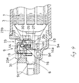
- the heights of seat portions 15a, 16a formed on the spring support portion 15, 16 are set as follows. As shown in Figure 3 the height C of the position where the brush 13 is mounted is different by a value substantially corresponding to a length X of the brush springs 13, 14 from the height D of the position where the brush spring 14 is mounted (D ⁇ C + X). Further, as shown in Figures 8 and 9 relationship is described in more detail as follows. That is, the seat portion 15a of the spring support position 15 is positioned at a height C measured from the cylindrical bottom portion 9b, and the seat portion 16a of the spring support portion 16 is positioned at a height D from the Cylindrical bottom portion 9b.
- L X - d.
- the holder stay unit 9 has a recessed portion 19 formed to the outside upper periphery of the cylindrical portion 9a thereof with respect to the horizontal line H and passing-through holes 20, 21, into which the opposite leg portions 23b, 23c of the brush holder to be described later are inserted from the outside, are formed to the right and left positions of the recessed portion 19.
- These passing-through holes 20, 21 are disposed inwardly of the spring support portions 15, 16 in the right and left directions and outwardly of the commutator 10 in the right and left directions and are symmetrical with respect to the vertical line V.
- these passing-through holes 20, 21 have a substantially square shape, the peripheral edges thereof is formed with taper-shaped portions 20a, 21a each having a wide outside portion and a narrow inside portion which is gradually narrowed from the wide outside portion.
- a guide member 22 projecting to the commutator 10 side is integrally formed to the inner periphery of the recessed portion 19 between the opposite passing-through holes 20, 21, and guide surfaces 22a, 22b, which are formed on the right and left sides of the guide member 22, extend from the taper-shaped portions 20a, 21a of the passing-through holes to positions in the vicinities substantially on the opposite sides of the commutator 10 in the diametrical direction thereof.
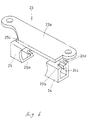
- Reference numeral 23 designates a brush holder which is integrally formed to substantially a C-shape and a mounting plate 23a, opposite leg portions 23b, 23c, and quadrangular-prism-shaped brush accommodation units 24, 25.
- Each unit 24, 25 has both open bottoms formed at the extreme ends of the opposite leg portions 23b, 23c and brushes 26, 27 are accommodated therein in such a manner that they can emerge from and retract into the brush accommodation units.
- the brush holder 23, which is arranged as a unit and has the brushes 26, 27 accommodated therein, is mounted on the holder stay unit 9, in which an armature assembly composed of the armature shaft 6, armature core 7, commutator and the like is preassembled, through the following mounting structure.
- the brush springs 13, 14 are presupported by the spring support portions 15, 16 and further the ends 13a, 14a of the brush springs 13, 14 are locked by the locking portions 17, 18 and in this state the opposite leg portions 23b, 23c of the brush holder are inserted into the passing-through holes 20, 21, respectively.
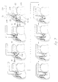
- the other ends 13b, 14b of the springs are located at the inserting paths as described above, and as shown in Figure 7, when the opposite leg portions 23b, 23c are gradually inserted, projections 24a, 25a formed to the outside corners on the right and left sides of the extreme ends of the brush accommodation units 24, 25 abut against the other ends of the springs and depress them toward the direction in which the brush springs 13, 14 are urged.
- the brushes 26, 27 accommodated in the brush accommodation units 24, 25 are inserted by being guided by the guide surfaces 22a, 22b of the guide member 22 until the extreme ends to be inserted thereof come into contact with the commutator 10 and thereafter inserted in the state that they are guided by the commutator 10.
- the other ends 13b, 14b of the springs are released from the projections 24a, 25a of the brush accommodation units and abut against the outside surfaces of the brushes 26, 27 in the diametrical direction thereof to elastically urge the brushes 26, 27 toward the commutator 10.
- the mounting plate 23a abuts against the outside periphery of the recessed portion 19 to regulate the further insertion of the opposite leg portions 23b, 23c.
- the brush holder 23 can be integrally mounted on the holder stay unit 9.
- reference numerals 23d, 23e, 24b and 25b in the figures designate fret grooves for a pig tail 30 formed to each of the opposite leg portions 23b, 23c and brush accommodation units 24, 25, reference numerals 24c, 25c, designate grooves for inserting the other ends 13b, 14b, of the spring therein and further reference numeral 31 designates an external connection terminal to which the extreme end of the fretted pig tail 30 is connected.
- the brush unit is formed by assembling the brushes 26, 27 to a pair of the brush accommodation units 24, 25 formed to the brush holder 23, respectively, the brushes 26, 27 can be stably held by the brush accommodation units 24, 25, it is not necessary to form a brush unit to each brush, the number of parts can be reduced, and further the number of processes for an assembly job can be also reduced.
- the brush springs 13, 14 are not assembled to the brush holder 23 but assembled to the holder stay unit 9 and further the brushes 26, 27 are elastically depressed at the moment when the brushes 26, 27 substantially reach the opposite side positions of the commutator 10 in the diametrical direction thereof based on the insertion and assembly of the brush holder 23 to the holder stay unit 9.
- the brushes do not greatly project from the brush unit as in the case in which the brush springs are assembled to the brush holder, whereby the brushes 26, 27 are prevented from being in hitting contact with other parts, and thus it is not necessary at all that the brushes 26, 27 are temporarily held by the brush holder 23.
- the brushes 26, 27 are first inserted into the passing-through holes 20, 21 by being guided by the taper-shaped potions 20a, 21a of the passing-through holes 20, 21 and then inserted by being guided by the guide surfaces 22a, 22b of the guide member 22 until the extreme ends to be inserted of the brushes 26, 27 come into contact with the commutator 10, and thereafter the brushes 26, 27 reach the opposite side positions of the commutator in the diametrical direction thereof in the state that they are guided by the commutator 10. Therefore, the brushes can be easily guided to a proper position.
- the brush unit when the brush unit is assembled, it is substantially only the brushes 26, 27 that come into contact with the commutator 10 and the guide receiving portion which is formed at the extreme end of the leaf spring is not in sliding contact with the commutator as in prior art. As a result, there is no possibility that the surface of the commutator is scratched by the guide receiving portion.
- the brush springs 13, 14 used in this embodiment are of the twisted coil type, there can be prevented a disadvantage that the leaf spring is vibrated by the vibration produced by the rotation of the commutator and transmitted to the leaf spring through the brushes and noise is produced by the vibration of the leaf spring as in the case in which the leaf spring is used.
- the brush unit is assembled from the outer periphery on the upper side of the cylindrical portion 9a of the holder stay unit, the brush unit and the speed reduction mechanism can be assembled from the same direction in such a case as this embodiment in which the speed reduction mechanism such as the worm wheel and the like are assembled from the upper side of the end case 4, which greatly contributes to the simplification of an automatic assembly line when the motor 1 is assembled on this line.
- the present motor is arranged as described above, when the brushes are to be assembled to the motor, the opposite leg portions of the brush holder having the brushes assembled thereto and arranged as a unit are inserted and assembled to the holder stay unit to which the armature assembly is preassembled through the passing-through holes.
- the brush unit is formed by assembling the brush to each of a pair of the brush accommodation units formed to the brush holder, these brushes can be stably held by the brush accommodation units.
- the pair of brushes can be assembled to the single brush unit, a brush unit need not be formed to each brush, and thus not only the number of parts can be reduced but also the number of processes for an assembly job also can be reduced.
- the springs for elastically depressing the brushes are assembled to the holder stay unit, and the brushes are elastically depressed at the moment when the brushes substantially reach the opposite side positions of the commutator in the diametrical direction thereof based on the insertion and assembly of the brush holder to the holder stay unit.
- the brushes do not greatly project from the brush unit as in the case in which the brush springs are preassembled to the brush holder, whereby the brushes are prevented from being in hitting contact with other parts, and thus it is not necessary at all that the brushes are tentatively held to prevent the brushes to greatly project from the brush unit.
- the brush unit when the brush unit is assembled, it is substantially only the brushes that come into contact with the commutator and the guide receiving portion which is formed at the extreme end of the leaf spring is not in sliding contact with the commutator as in prior art. As a result, a possibility that the surface of the commutator is scratched by the guide receiving portion can be securely prevented.
Landscapes
- Engineering & Computer Science (AREA)
- Power Engineering (AREA)
- Motor Or Generator Current Collectors (AREA)
- Motor Or Generator Frames (AREA)
Description
- The present invention relates to a brush assembly structure for a motor used to operate, for example, electric parts of an automobile.
- In general, this kind of brush assembly is mounted so that it can come into elastically sliding contact with the commutator formed on an armature shaft. As a result, when no commutator is present, the brushes project towards the center of the shaft beyond the position of the sliding surface of the commutator. Therefore, if an attempt is made to assemble the armature when the brushes project towards the assembly of the motor, the armature cannot be substantially assembled because it is blocked by the brushes. To cope with this problem, there is a known method in which each brush is tentatively held against a spring at a position spaced apart from a commutator. The armature is assembled in this state and then the tentatively held brush is released. In this case, an operation for tentatively holding each brush and an operation for releasing the tentatively held brush are needed. These operations are time-consuming and troublesome and there is a possibility that the releasing operation may be forgotten sometimes.
- Consequently, as disclosed in Japanese Utility Model Unexamined Publication No. Sho 58-115862 and Japanese Utility Model Unexamined Publication No. Sho 58-166262, there is proposed a method by which a brush unit having brushes preset in a brush holder is prepared, an opening is formed to a holder stay unit to which the brush holder is to be mounted and then the brush unit is assembled through the opening after an armature has been preassembled. In the former Publication, however, since brush units must be formed for respective brushes and engaged and assembled, respectively, as many brush units as many as brushes are necessary and thus the number of parts is increased and workability is lowered. Further, since the brush is urged to the state that it projects significantly from the brush unit by a spring assembled in the brush unit, a problem arises in that the brush can strike other parts and is liable to be damaged by them before the brush unit is assembled to the holder stay unit, and the like.
- On the other hand, in the latter Publication, since a pair of brushes are assembled in a brush unit, there is an advantage that the number of brush units can be reduced to half those of the former Publication. In this case, however, since a brush accommodation unit is not used, each brush is urged and held in the state that it is exposed through a leaf spring fixed to a brush holder. Thus, the brush cannot be stably held by the brush accommodation unit and further since a guide receiving portion is formed at the extreme end of the leaf spring to guide the brushes so that they come into sliding contact with a commutator in such a manner that the guide receiving portion is in contact with the periphery of the commutator to increase the distance between the confronting brushes. Consequently, in this case, a problem arises in that there is a possibility that the surface of the commutator is scratched by the guide receiving unit in contact therewith.
- US-A-4593220 describes a motor having features set out in the pre-characterising part of
claim 1. - Taking the above into consideration, the present invention has been created for the purpose of providing a brush assembly structure for a motor by which aforesaid drawbacks can be overcome.
- According to the present invention there is provided a motor having a pair of brushes which are accommodated in a pair of brush accommodation units formed to a brush holder so that they can emerge from and retract into the brush accommodation units, respectively, and come into elastic sliding contact with the opposite side positions of a commutator supported by a casing in the diametrical direction thereof, said brush holder being formed to substantially a C-shape in such that the extreme ends of the opposite leg portions of said brush holder confront the opposite side positions of said commutator, said brush accommodation units being formed at each end of said opposite leg portions, said brush accommodation units having opposing open ends for allowing the brushes to emerge from a retract into the brush accommodation unit, a holder stay unit being provided on the casing so that the brush holder can be attached to the holder stay unit in the diemetrical direction, characterised in that supporting springs for elastically depressing said brushes are provided on said holder stay unit, said springs being arranged so that they become elastically deformed in accordance with the movements of said brush accommodation unit when it is inserted into the mounting position and elastically depressing said brushes accommodated in said brush accommodation unit at the moment when said brush accommodation unit reaches the mounting position and at the same time said springs reach the outer open ends of said brush accommodation unit.
- Since the present invention is arranged as described above, a pair of the brushes are accommodated in the brush accommodation units formed to the brush holder in such a way that they are retracted and not urged to a projected position by the springs and the brush holder and brushes can be assembled as a unit to the holder stay unit, whereby the brushes can be protected and an assembly job can be simplified.
- The invention will be described now, by way of example only, with particular reference to the accompanying drawings. In the drawings.
- Figure 1 is a plan view of a motor;
- Figure 2 is a plan view of a holder stay unit;
- Figure 3 is a horizontal cross sectional view of the holder stay unit;
- Figure 4 is a vertical cross sectional view of the holder stay unit;
- Figure 5 is a side view of the holder stay unit;
- Figure 6 is a perspective view of a brush holder;
- Figure 7 is a diagram explaining the processes for assembling a brush unit to the holder stay unit; and
- Figures 8 and 9 are views showing the positional relationship of the springs and their supports.
- Next, an embodiment of the present invention will be described with reference to the drawings, wherein
reference numeral 1 designates a motor with a speed reduction mechanism serving as a power source for automotive electric parts and themotor 1 has acasing 2 composed of acylindrical yoke 3 with a bottom and anend case 4 assembled to the open end of theyoke 3. Although theyoke 3 has various parts such as apermanent magnet 5, anarmature shaft 6, anarmature core 7 and the like assembled thereto and theend case 4 has the speed reduction mechanism such as aworm gear 6a formed at the extreme end of thearmature shaft 6, a worm wheel (not shown) to be meshed with theworm gear 6a, and the like, the basic arrangement of these parts is the same as that of conventional ones. - In the
above casing 2, the yoke side end of theend case 4 is formed to aholder stay unit 9 to which a brush unit to be described later is assembled. More specifically, theholder stay unit 9 has a cylindrical shape with a bottom and acommutator 10 integrally formed with thearmature shaft 6 is disposed in thecylindrical portion 9a of theholder stay unit 9. Theholder stay unit 9 has a width B in a horizontal line H direction which is longer than a width A in a vertical line V direction which is perpendicular to the shaft center of the armature shaft 6 (A < B). Aninserting hole 9c through which theworm gear 6a is inserted is formed at the center of thecylindrical bottom portion 9b of theholder stay unit 9 and anengaging groove 9d for abearing 12 for rotatably supporting thearmature shaft 6 is formed to the peripheral edge of theinserting hole 9c. - Further, right and left
spring support portions portions cylindrical bottom portion 9b, andcoil portion 13c, 14c of a pair of right and left twisted coiltype brush springs spring support portions ends brush springs locking portions spring support portions locking portions locking portions spring support portions opposite ends brush springs portions 13c and 14c of thebrush springs spring support portions ends locking portions cylindrical portion 9a and locked, thesprings other ends springs leg portions 23b, 23c of a brush holder to be described later are inserted. It should be noted that the heights ofseat portions spring support portion brush 13 is mounted is different by a value substantially corresponding to a length X of thebrush springs brush spring 14 is mounted (D ≒ C + X). Further, as shown in Figures 8 and 9 relationship is described in more detail as follows. That is, theseat portion 15a of thespring support position 15 is positioned at a height C measured from thecylindrical bottom portion 9b, and theseat portion 16a of thespring support portion 16 is positioned at a height D from theCylindrical bottom portion 9b. As a result, the height difference between theseat portion 15a and theseat portion 16a is represented as L (L = D - C). When the diameter of the coil is d the height difference L is set such that the length X of the brush spring minus the diameter d of the coil, theoretically given as following formula; L = X - d. - Furthermore, when the distance between the
seat portion 15a and the position of thebrush 26 present by the brush spring is represented as h, the height difference L is theoretically given as following formula; L = h - (1/2) x d. As a result, when thesprings other ends common brush springs - Further, the
holder stay unit 9 has arecessed portion 19 formed to the outside upper periphery of thecylindrical portion 9a thereof with respect to the horizontal line H and passing-throughholes opposite leg portions 23b, 23c of the brush holder to be described later are inserted from the outside, are formed to the right and left positions of therecessed portion 19. These passing-throughholes spring support portions commutator 10 in the right and left directions and are symmetrical with respect to the vertical line V. Further, although these passing-throughholes shaped portions guide member 22 projecting to thecommutator 10 side is integrally formed to the inner periphery of therecessed portion 19 between the opposite passing-throughholes guide surfaces guide member 22, extend from the taper-shaped portions commutator 10 in the diametrical direction thereof. -
Reference numeral 23 designates a brush holder which is integrally formed to substantially a C-shape and amounting plate 23a,opposite leg portions 23b, 23c, and quadrangular-prism-shapedbrush accommodation units unit opposite leg portions 23b, 23c andbrushes brush holder 23, which is arranged as a unit and has thebrushes holder stay unit 9, in which an armature assembly composed of thearmature shaft 6,armature core 7, commutator and the like is preassembled, through the following mounting structure. More specifically, when thebrush holder 23 is to be mounted, thebrush springs spring support portions ends brush springs locking portions opposite leg portions 23b, 23c of the brush holder are inserted into the passing-throughholes other ends opposite leg portions 23b, 23c are gradually inserted,projections brush accommodation units brush springs - On the other hand, the
brushes brush accommodation units guide surfaces guide member 22 until the extreme ends to be inserted thereof come into contact with thecommutator 10 and thereafter inserted in the state that they are guided by thecommutator 10. At the moment when thebrushes commutator 10 in the diametrical direction thereof, theother ends projections brushes brushes commutator 10. Further, when thebrushes commutator 10 in the diametrical direction thereof, themounting plate 23a abuts against the outside periphery of therecessed portion 19 to regulate the further insertion of theopposite leg portions 23b, 23c. When themounting plate 23a is fixed to therecessed portion 19 by ascrew 28 in this state, thebrush holder 23 can be integrally mounted on theholder stay unit 9. - Note,
reference numerals pig tail 30 formed to each of theopposite leg portions 23b, 23c andbrush accommodation units reference numerals other ends further reference numeral 31 designates an external connection terminal to which the extreme end of thefretted pig tail 30 is connected. - In the embodiment of the present invention arranged as described above, when the
brushes motor 1, the brush springs 13, 14 are assembled to thecylindrical bottom portion 9a of theholder stay unit 9 preformed to thecasing 2 and the armature assembly is assembled to theholder stay unit 9, as described above. Then, in this state, theopposite leg portions 23b, 23c of thebrush holder 23 which has thebrushes holes holder stay unit 9. In this case, however, since the brush unit is formed by assembling thebrushes brush accommodation units brush holder 23, respectively, thebrushes brush accommodation units - In the above embodiment, the brush springs 13, 14 are not assembled to the
brush holder 23 but assembled to theholder stay unit 9 and further thebrushes brushes commutator 10 in the diametrical direction thereof based on the insertion and assembly of thebrush holder 23 to theholder stay unit 9. As a result, when the brush unit is assembled to the holder stay unit, the brushes do not greatly project from the brush unit as in the case in which the brush springs are assembled to the brush holder, whereby thebrushes brushes brush holder 23. - Further, in this embodiment, when the brush unit is assembled to the
holder stay unit 9, thebrushes holes potions holes guide member 22 until the extreme ends to be inserted of thebrushes commutator 10, and thereafter thebrushes commutator 10. Therefore, the brushes can be easily guided to a proper position. Furthermore, when the brush unit is assembled, it is substantially only thebrushes commutator 10 and the guide receiving portion which is formed at the extreme end of the leaf spring is not in sliding contact with the commutator as in prior art. As a result, there is no possibility that the surface of the commutator is scratched by the guide receiving portion. - Furthermore, since the brush springs 13, 14 used in this embodiment are of the twisted coil type, there can be prevented a disadvantage that the leaf spring is vibrated by the vibration produced by the rotation of the commutator and transmitted to the leaf spring through the brushes and noise is produced by the vibration of the leaf spring as in the case in which the leaf spring is used.
- Further, since the brush unit is assembled from the outer periphery on the upper side of the
cylindrical portion 9a of the holder stay unit, the brush unit and the speed reduction mechanism can be assembled from the same direction in such a case as this embodiment in which the speed reduction mechanism such as the worm wheel and the like are assembled from the upper side of theend case 4, which greatly contributes to the simplification of an automatic assembly line when themotor 1 is assembled on this line. - In short, since the present motor is arranged as described above, when the brushes are to be assembled to the motor, the opposite leg portions of the brush holder having the brushes assembled thereto and arranged as a unit are inserted and assembled to the holder stay unit to which the armature assembly is preassembled through the passing-through holes. In this case, since the brush unit is formed by assembling the brush to each of a pair of the brush accommodation units formed to the brush holder, these brushes can be stably held by the brush accommodation units. Further, since the pair of brushes can be assembled to the single brush unit, a brush unit need not be formed to each brush, and thus not only the number of parts can be reduced but also the number of processes for an assembly job also can be reduced.
- In addition, according to the present embodiment, the springs for elastically depressing the brushes are assembled to the holder stay unit, and the brushes are elastically depressed at the moment when the brushes substantially reach the opposite side positions of the commutator in the diametrical direction thereof based on the insertion and assembly of the brush holder to the holder stay unit. As a result, when the brush unit is assembled to the holder stay unit, the brushes do not greatly project from the brush unit as in the case in which the brush springs are preassembled to the brush holder, whereby the brushes are prevented from being in hitting contact with other parts, and thus it is not necessary at all that the brushes are tentatively held to prevent the brushes to greatly project from the brush unit.
- Furthermore, when the brush unit is assembled, it is substantially only the brushes that come into contact with the commutator and the guide receiving portion which is formed at the extreme end of the leaf spring is not in sliding contact with the commutator as in prior art. As a result, a possibility that the surface of the commutator is scratched by the guide receiving portion can be securely prevented.
Claims (1)
- A motor having a pair of brushes (26, 27) which are accommodated in a pair of brush accommodation units (24, 25) formed to a brush holder (23) so that they can emerge from and retract into the brush accommodation units, respectively, and come into elastic sliding contact with the opposite side positions of a commutator (10) supported by a casing (2) in the diametrical direction thereof, said brush holder (23) being formed to substantially a C-shape in such that the extreme ends of the opposite leg portions (23b, 23c) of said brush holder confront the opposite side positions of said commutator, said brush accommodation units (24, 25) being formed at each end of said opposite leg portions, said brush accommodation units having opposing open ends for allowing the brushes (26, 27) to emerge from a retract into the brush accommodation unit, a holder stay unit (9) being provided on the casing (2) so that the brush holder can be attached to the holder stay unit in the diemetrical direction,
characterised in that supporting springs (13, 14) for elastically depressing said brushes (26, 27) are provided on said holder stay unit, said springs being arranged so that they become elastically deformed in accordance with the movements of said brush accommodation unit when it is inserted into the mounting position and elastically depressing said brushes (26, 27) accommodated in said brush accommodation unit at the moment when said brush accommodation unit reaches the mounting position and at the same time said springs reach the outer open ends of said brush accommodation unit.
Applications Claiming Priority (2)
| Application Number | Priority Date | Filing Date | Title |
|---|---|---|---|
| JP15068/93 | 1993-03-05 | ||
| JP1506893 | 1993-03-05 |
Publications (3)
| Publication Number | Publication Date |
|---|---|
| EP0614251A2 EP0614251A2 (en) | 1994-09-07 |
| EP0614251A3 EP0614251A3 (en) | 1995-01-25 |
| EP0614251B1 true EP0614251B1 (en) | 1997-11-19 |
Family
ID=11878536
Family Applications (1)
| Application Number | Title | Priority Date | Filing Date |
|---|---|---|---|
| EP94301528A Expired - Lifetime EP0614251B1 (en) | 1993-03-05 | 1994-03-03 | Brush assembly structure for motor |
Country Status (5)
| Country | Link |
|---|---|
| US (1) | US5506461A (en) |
| EP (1) | EP0614251B1 (en) |
| KR (1) | KR200177982Y1 (en) |
| CA (1) | CA2116988C (en) |
| DE (1) | DE69406824T2 (en) |
Families Citing this family (13)
| Publication number | Priority date | Publication date | Assignee | Title |
|---|---|---|---|---|
| US5818142A (en) * | 1995-07-27 | 1998-10-06 | Black & Decker Inc. | Motor pack armature support with brush holder assembly |
| FR2743212B1 (en) * | 1995-12-27 | 1998-03-13 | Valeo Systemes Dessuyage | COMPACT DIRECT CURRENT MOTOR FOLLOWING THE AXIAL STEERING |
| US5753992A (en) * | 1996-11-07 | 1998-05-19 | Delco Remy America Inc | Single piece brush fixture for dynamoelectric machine |
| US6727615B2 (en) * | 1997-06-26 | 2004-04-27 | Robert Bosch Gmbh | Electric drive unit with a cylindrical bearing indented in the housing |
| DE19727118A1 (en) * | 1997-06-26 | 1999-01-28 | Bosch Gmbh Robert | Electric drive unit |
| DE19858233A1 (en) * | 1998-12-17 | 2000-06-29 | Bosch Gmbh Robert | Electric gear motor for vehicle units |
| JP2001268856A (en) * | 2000-03-22 | 2001-09-28 | Asmo Co Ltd | motor |
| US6617744B2 (en) * | 2000-08-23 | 2003-09-09 | Siemens Vdo Automotive Inc. | DC motor brush card assembly having attaching structures and multiple choke coils with elongated portions |
| US7696666B2 (en) * | 2006-10-06 | 2010-04-13 | Remy Technologies, L.L.C. | Dynamoelectric machine grommet |
| US7705512B2 (en) * | 2006-10-06 | 2010-04-27 | Remy International, Inc. | Dynamoelectric machine conductor |
| US7466056B2 (en) * | 2006-10-06 | 2008-12-16 | Remi International, Inc | Dynamoelectric machine brush holder assembly and method |
| US20080084133A1 (en) * | 2006-10-06 | 2008-04-10 | Steven Burton | Dynamoelectric machine brush and method |
| DE102009001418A1 (en) * | 2009-03-10 | 2010-09-16 | Robert Bosch Gmbh | Brush bearing device and electric machine with a brush bearing device |
Family Cites Families (5)
| Publication number | Priority date | Publication date | Assignee | Title |
|---|---|---|---|---|
| JPS58115862A (en) * | 1981-12-28 | 1983-07-09 | Seiko Epson Corp | Manufacturing method of thin film transistor |
| CH657073A5 (en) * | 1982-03-09 | 1986-08-15 | Guest Medical & Dental Prod | DEVICE FOR DETERMINING THE REDUCTION SPEED OF RED BLOOD BODIES. |
| US4593220A (en) * | 1984-07-12 | 1986-06-03 | Black & Decker Inc. | Brush bearing sub-assembly for electric motor |
| EP0175993B1 (en) * | 1984-09-19 | 1987-10-28 | Siemens Aktiengesellschaft | Hammer-type brush holder system for a commutator motor |
| GB2189943A (en) * | 1986-05-02 | 1987-11-04 | Johnson Electric Ind Mfg | Assembling brush gear in an electric motor |
-
1994
- 1994-02-24 KR KR2019940003377U patent/KR200177982Y1/en not_active Expired - Fee Related
- 1994-03-03 EP EP94301528A patent/EP0614251B1/en not_active Expired - Lifetime
- 1994-03-03 DE DE69406824T patent/DE69406824T2/en not_active Expired - Fee Related
- 1994-03-04 CA CA002116988A patent/CA2116988C/en not_active Expired - Fee Related
- 1994-03-04 US US08/205,743 patent/US5506461A/en not_active Expired - Lifetime
Also Published As
| Publication number | Publication date |
|---|---|
| CA2116988A1 (en) | 1994-09-06 |
| KR940023644U (en) | 1994-10-22 |
| KR200177982Y1 (en) | 2000-04-15 |
| CA2116988C (en) | 1999-08-17 |
| DE69406824T2 (en) | 1998-06-25 |
| EP0614251A2 (en) | 1994-09-07 |
| US5506461A (en) | 1996-04-09 |
| EP0614251A3 (en) | 1995-01-25 |
| DE69406824D1 (en) | 1998-01-02 |
Similar Documents
| Publication | Publication Date | Title |
|---|---|---|
| EP0614251A2 (en) | Brush assembly structure for motor | |
| US3988623A (en) | Case for a small-sized electric motor | |
| US4322647A (en) | Motor assembly | |
| US4644204A (en) | Motor housing and end shield mount | |
| US5187400A (en) | Vibration-proof stepping motor with built-up stator | |
| KR102101713B1 (en) | Brush fixing device for motor | |
| US6886969B2 (en) | Room lamp for vehicle | |
| US5250866A (en) | Structure for fixing permanent magnets in motor | |
| US6508143B2 (en) | Structure for mounting to steering wheel | |
| US4906884A (en) | Flat motor | |
| JP4492658B2 (en) | Vehicle alternator | |
| US4368938A (en) | Small electric motor | |
| WO1995001264A1 (en) | A vehicle radiator grille, a headlight housing and a method of mounting the grille onto a vehicle | |
| JPH0140311Y2 (en) | ||
| JPH0130864Y2 (en) | ||
| JP3388124B2 (en) | Connection terminal mounting structure | |
| JP3351897B2 (en) | Assembling structure of brush urging machine in motor | |
| JP2000150062A (en) | Connector mounting jig | |
| KR900007222Y1 (en) | Magnetic protection support of the motor | |
| JP3875525B2 (en) | motor | |
| JP7845947B2 (en) | Electrical component housing box | |
| JPH034132Y2 (en) | ||
| KR100217783B1 (en) | Electromagnetic rotary actuator and housing for electric devices | |
| JP2584189Y2 (en) | Assembling structure of brush in motor | |
| JP2000224815A (en) | Small motor |
Legal Events
| Date | Code | Title | Description |
|---|---|---|---|
| PUAI | Public reference made under article 153(3) epc to a published international application that has entered the european phase |
Free format text: ORIGINAL CODE: 0009012 |
|
| AK | Designated contracting states |
Kind code of ref document: A2 Designated state(s): DE FR GB |
|
| PUAL | Search report despatched |
Free format text: ORIGINAL CODE: 0009013 |
|
| AK | Designated contracting states |
Kind code of ref document: A3 Designated state(s): DE FR GB |
|
| RHK1 | Main classification (correction) |
Ipc: H02K 5/14 |
|
| 17P | Request for examination filed |
Effective date: 19950519 |
|
| 17Q | First examination report despatched |
Effective date: 19960730 |
|
| RAP1 | Party data changed (applicant data changed or rights of an application transferred) |
Owner name: MITSUBA CORPORATION |
|
| GRAG | Despatch of communication of intention to grant |
Free format text: ORIGINAL CODE: EPIDOS AGRA |
|
| GRAH | Despatch of communication of intention to grant a patent |
Free format text: ORIGINAL CODE: EPIDOS IGRA |
|
| GRAH | Despatch of communication of intention to grant a patent |
Free format text: ORIGINAL CODE: EPIDOS IGRA |
|
| GRAA | (expected) grant |
Free format text: ORIGINAL CODE: 0009210 |
|
| AK | Designated contracting states |
Kind code of ref document: B1 Designated state(s): DE FR GB |
|
| REF | Corresponds to: |
Ref document number: 69406824 Country of ref document: DE Date of ref document: 19980102 |
|
| ET | Fr: translation filed | ||
| PLBE | No opposition filed within time limit |
Free format text: ORIGINAL CODE: 0009261 |
|
| STAA | Information on the status of an ep patent application or granted ep patent |
Free format text: STATUS: NO OPPOSITION FILED WITHIN TIME LIMIT |
|
| 26N | No opposition filed | ||
| REG | Reference to a national code |
Ref country code: GB Ref legal event code: IF02 |
|
| PGFP | Annual fee paid to national office [announced via postgrant information from national office to epo] |
Ref country code: GB Payment date: 20050302 Year of fee payment: 12 |
|
| PG25 | Lapsed in a contracting state [announced via postgrant information from national office to epo] |
Ref country code: GB Free format text: LAPSE BECAUSE OF NON-PAYMENT OF DUE FEES Effective date: 20060303 |
|
| GBPC | Gb: european patent ceased through non-payment of renewal fee |
Effective date: 20060303 |
|
| PGFP | Annual fee paid to national office [announced via postgrant information from national office to epo] |
Ref country code: FR Payment date: 20080311 Year of fee payment: 15 Ref country code: DE Payment date: 20080228 Year of fee payment: 15 |
|
| REG | Reference to a national code |
Ref country code: FR Ref legal event code: ST Effective date: 20091130 |
|
| PG25 | Lapsed in a contracting state [announced via postgrant information from national office to epo] |
Ref country code: DE Free format text: LAPSE BECAUSE OF NON-PAYMENT OF DUE FEES Effective date: 20091001 |
|
| PG25 | Lapsed in a contracting state [announced via postgrant information from national office to epo] |
Ref country code: FR Free format text: LAPSE BECAUSE OF NON-PAYMENT OF DUE FEES Effective date: 20091123 |