EP0613557B1 - Ultrasonic holographic imaging apparatus having zoom feature - Google Patents
Ultrasonic holographic imaging apparatus having zoom feature Download PDFInfo
- Publication number
- EP0613557B1 EP0613557B1 EP93900662A EP93900662A EP0613557B1 EP 0613557 B1 EP0613557 B1 EP 0613557B1 EP 93900662 A EP93900662 A EP 93900662A EP 93900662 A EP93900662 A EP 93900662A EP 0613557 B1 EP0613557 B1 EP 0613557B1
- Authority
- EP
- European Patent Office
- Prior art keywords
- ultrasonic
- imaging apparatus
- holographic imaging
- lens
- lens system
- Prior art date
- Legal status (The legal status is an assumption and is not a legal conclusion. Google has not performed a legal analysis and makes no representation as to the accuracy of the status listed.)
- Expired - Lifetime
Links
- 238000003384 imaging method Methods 0.000 title claims abstract description 28
- 238000001514 detection method Methods 0.000 claims description 10
- 230000001427 coherent effect Effects 0.000 claims description 6
- 239000007788 liquid Substances 0.000 claims description 5
- 230000008859 change Effects 0.000 claims description 4
- 230000008878 coupling Effects 0.000 claims description 4
- 238000010168 coupling process Methods 0.000 claims description 4
- 238000005859 coupling reaction Methods 0.000 claims description 4
- 230000002452 interceptive effect Effects 0.000 claims 1
- 230000003287 optical effect Effects 0.000 abstract description 5
- 230000004044 response Effects 0.000 abstract description 2
- 239000012528 membrane Substances 0.000 description 4
- 238000001093 holography Methods 0.000 description 3
- 210000004872 soft tissue Anatomy 0.000 description 3
- 230000005855 radiation Effects 0.000 description 2
- 230000000694 effects Effects 0.000 description 1
- 238000011156 evaluation Methods 0.000 description 1
- 239000012530 fluid Substances 0.000 description 1
- 239000000463 material Substances 0.000 description 1
- 238000009659 non-destructive testing Methods 0.000 description 1
- 238000002604 ultrasonography Methods 0.000 description 1
Images


Classifications
-
- G—PHYSICS
- G03—PHOTOGRAPHY; CINEMATOGRAPHY; ANALOGOUS TECHNIQUES USING WAVES OTHER THAN OPTICAL WAVES; ELECTROGRAPHY; HOLOGRAPHY
- G03H—HOLOGRAPHIC PROCESSES OR APPARATUS
- G03H3/00—Holographic processes or apparatus using ultrasonic, sonic or infrasonic waves for obtaining holograms; Processes or apparatus for obtaining an optical image from them
-
- G—PHYSICS
- G03—PHOTOGRAPHY; CINEMATOGRAPHY; ANALOGOUS TECHNIQUES USING WAVES OTHER THAN OPTICAL WAVES; ELECTROGRAPHY; HOLOGRAPHY
- G03H—HOLOGRAPHIC PROCESSES OR APPARATUS
- G03H1/00—Holographic processes or apparatus using light, infrared or ultraviolet waves for obtaining holograms or for obtaining an image from them; Details peculiar thereto
- G03H1/04—Processes or apparatus for producing holograms
- G03H1/0402—Recording geometries or arrangements
- G03H2001/0428—Image holography, i.e. an image of the object or holobject is recorded
-
- G—PHYSICS
- G03—PHOTOGRAPHY; CINEMATOGRAPHY; ANALOGOUS TECHNIQUES USING WAVES OTHER THAN OPTICAL WAVES; ELECTROGRAPHY; HOLOGRAPHY
- G03H—HOLOGRAPHIC PROCESSES OR APPARATUS
- G03H1/00—Holographic processes or apparatus using light, infrared or ultraviolet waves for obtaining holograms or for obtaining an image from them; Details peculiar thereto
- G03H1/22—Processes or apparatus for obtaining an optical image from holograms
- G03H1/2202—Reconstruction geometries or arrangements
- G03H1/2205—Reconstruction geometries or arrangements using downstream optical component
- G03H2001/2207—Spatial filter, e.g. for suppressing higher diffraction orders
-
- Y—GENERAL TAGGING OF NEW TECHNOLOGICAL DEVELOPMENTS; GENERAL TAGGING OF CROSS-SECTIONAL TECHNOLOGIES SPANNING OVER SEVERAL SECTIONS OF THE IPC; TECHNICAL SUBJECTS COVERED BY FORMER USPC CROSS-REFERENCE ART COLLECTIONS [XRACs] AND DIGESTS
- Y10—TECHNICAL SUBJECTS COVERED BY FORMER USPC
- Y10S—TECHNICAL SUBJECTS COVERED BY FORMER USPC CROSS-REFERENCE ART COLLECTIONS [XRACs] AND DIGESTS
- Y10S359/00—Optical: systems and elements
- Y10S359/901—Acoustic holography
Definitions
- This invention relates to ultrasonic holographic imaging apparatus for viewing imaged holographic information of the internal structure of an object at different magnifications.
- ultrasonic holography Although commercial application of ultrasonic holography as been accurately pursued by many persons in the scientific and industrial communities for many years, only limited results have been obtained even though it was once thought that ultrasonic holography held great promise. It was felt that the application of ultrasonic holography was particularly applicable to the fields of nondestructive testing of materials and medical diagnostics of soft tissues that are relatively transparent to ultrasonic radiation.
- One of the principal problems that has been encountered and not effectively resolved is the difficulty of obtaining quality and consistent images.
- a further problem has been the inability to vary the magnification of the image while maintaining a consistent high quality image.
- Fig. 1 shows a typical "real time" prior art ultrasonic holographic imaging system generally designated with the numeral 10.
- the system 10 is intended to ultrasonically inspect the interior of an object 12 such as the soft tissue of a human limb.
- the ultrasonic holographic imaging system 10 generally has a hologram generating subsystem 14 for generating an ultrasonic hologram.
- the system 10 also includes a hologram viewing subsystem (optical-subsystem) 16 for optically viewing the interior of the object 12 from a first order diffraction from the formed ultrasonic hologram.
- optical-subsystem optical-subsystem
- the subsystem 14 includes an object ultrasonic transducer 18 for generating plane waves through a liquid or gel coupling medium 20 contained in a deformable membrane 22.
- the deformable membrane 22 intimately contacts the object 12 on one side and a deformable membrane 24 contacts the object on the other side to provide ultrasonic coupling with minimum energy loss or wave distortion.
- the deformable membrane 24 forms part of the side wall of a container 28 that contains a liquid coupling medium 30.
- the ultrasonic imaging lens system 32 for viewing a large field and focusing at a desired object focal plane 34.
- the prior art ultrasonic imaging lens system 32 focuses the ultrasonic energy onto a hologram detector surface 36.
- the ultrasonic imaging lens system 32 includes a large diameter object lens 38 that is moveable with respect to a large diameter lens 40 for moving the lens to different desired focal planes 34 in the object 12.
- the lens 40 is stationary and is positioned at a fixed focal length from the detector surface 36.
- the ultrasonic imaging lens system 32 includes a mirror 41 for reflecting the ultrasonic energy approximately 90° and onto the hologram detection surface 36 to form the hologram.
- a ultrasonic reference transducer 42 directs coherent ultrasonic plane waves through the liquid medium 30 at an off-axis angle to the hologram detector surface 36 to form the hologram.
- the hologram detection surface 36 is the liquid/gas interface surface that is supported in an isolated dish or mini-tank 44.
- the hologram viewing subsystem 16 includes an optical lens 45 to achieve an effective point source of a coherent light beam from a laser (not shown).
- the focused coherent light is reflected from a mirror 46 through a collimating optical lens 47 and then onto the hologram detector surface 36 to illuminate the hologram and generate diffracted optical images.
- the reflected coherent light radiation containing holographic information is directed back through the collimating lens 47 and separated into precisely defined diffracted orders in the focal plane of the collimating lens 47.
- a filter 48 is used to block all but a first diffracted order from a viewing lens 49 to enable a human eye, a photographic film or a video camera to record in "real time" the object at the object focal plane.
- a filter 48 is used to block all but a first diffracted order from a viewing lens 49 to enable a human eye, a photographic film or a video camera to record in "real time" the object at the object focal plane.
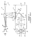
- One of the principal objects and advantages of this invention is to provide an improved ultrasonic holographic imaging apparatus that has the ability to change the magnification of the image relative to the object as well as change the focus to different planes in the object while maintaining consistent high quality images.
- the apparatus 50 includes a multiple lens system designated with the numeral 52 that includes two ultrasonic converging lenses 54 and 56 that are aligned along an optical axis 57.
- the multiple lens system 52 includes a lens support 58 for supporting the lens 54 and lens support 60 for independently supporting the lens 56.
- lens supports 58 and 59 include lead screws 62 and 64 respectively.
- the apparatus 50 includes lens support drives 66 and 68 that are connected to the lead screws 62 and 64 respectively for rotating the lead screws in either a forward or back rotation to precisely and accurately move the lens 54 and 56 relative to each other.
- the ultrasonic holographic imaging apparatus 50 includes a control system generally designated with the numeral 70 that includes lead screw encoders 72 and 74 for generating coding signals that are sent to a computer or microcontroller 76 that controls the position of the lens very accurately in response to input signals from operative control devices 78 and 80.
- the operator control device 78 is specifically provided for providing zoom signals to the computer to cause the computer to move both of the lens 54 and 56 relative to each other and in unison to obtain the desired magnification.
- the magnification varies between 0.25 and 4.
- the operator control device 80 inputs desired signals to move principally the lens 54 to and from the object 12 to focus at desired focal planes within the object to visually inspect the volume of the object.
- the applicant has found that such an ultrasonic holographic imaging apparatus 50 is quite capable in providing consistent and quality images at desired magnifications as well as being able to accurately focus the lens system within the volume of the object 12 to view different structures within the object 12.
- the focal object plane 34 of the multiple lens system, within the object 12 is the distance "O" and is known or selected by the operator. Similarly, the magnification of the image is selected by the operator.
- Such values are input to the computer 76 through the input devices 78 and 80.
- the computer 76 is programmed to receive the input values and to calculate the proper positions L 1 and L 2 for the lens 54 and 56.
- the positions of lens 54, L 1 , and 56, L 2 are calculated using the input values of "O" and "M” and the known focal lengths of lens 54 and 56, defined as F 1 and F 2 respectively, using the formulas (1) and (2):
- L 1 (- b ⁇ b 2 -4 ac )/2 a
- c [ MF 2 / ( MF 2 + F 1 )][ O - F 1 + F 1 / M ] 2 + O ( F 1 ) 2 / ( MF 2 + F 1 ) (3)
- L 2 ( MF 2 / F 1 ) ( O - L 1 - F 1 ) + F 2
- Such a system significantly increases the ability of an operator to observe the internal structure of an object, such as soft tissue of a human limb, at varying magnifications to make a proper medical evaluation.
Landscapes
- Physics & Mathematics (AREA)
- General Physics & Mathematics (AREA)
- Investigating Or Analyzing Materials By The Use Of Ultrasonic Waves (AREA)
- Ultra Sonic Daignosis Equipment (AREA)
- Focusing (AREA)
Abstract
Description
- This invention relates to ultrasonic holographic imaging apparatus for viewing imaged holographic information of the internal structure of an object at different magnifications.
- Although commercial application of ultrasonic holography as been accurately pursued by many persons in the scientific and industrial communities for many years, only limited results have been obtained even though it was once thought that ultrasonic holography held great promise. It was felt that the application of ultrasonic holography was particularly applicable to the fields of nondestructive testing of materials and medical diagnostics of soft tissues that are relatively transparent to ultrasonic radiation. One of the principal problems that has been encountered and not effectively resolved is the difficulty of obtaining quality and consistent images. A further problem has been the inability to vary the magnification of the image while maintaining a consistent high quality image.
- As background, Fig. 1 shows a typical "real time" prior art ultrasonic holographic imaging system generally designated with the
numeral 10. Thesystem 10 is intended to ultrasonically inspect the interior of anobject 12 such as the soft tissue of a human limb. The ultrasonicholographic imaging system 10 generally has a hologram generatingsubsystem 14 for generating an ultrasonic hologram. Thesystem 10 also includes a hologram viewing subsystem (optical-subsystem) 16 for optically viewing the interior of theobject 12 from a first order diffraction from the formed ultrasonic hologram. - The
subsystem 14 includes an objectultrasonic transducer 18 for generating plane waves through a liquid orgel coupling medium 20 contained in adeformable membrane 22. Thedeformable membrane 22 intimately contacts theobject 12 on one side and adeformable membrane 24 contacts the object on the other side to provide ultrasonic coupling with minimum energy loss or wave distortion. Thedeformable membrane 24 forms part of the side wall of acontainer 28 that contains aliquid coupling medium 30. - One of the principal components and the main concern of this invention is the provision of an ultrasonic
imaging lens system 32 for viewing a large field and focusing at a desired objectfocal plane 34. The prior art ultrasonicimaging lens system 32 focuses the ultrasonic energy onto ahologram detector surface 36. The ultrasonicimaging lens system 32 includes a largediameter object lens 38 that is moveable with respect to alarge diameter lens 40 for moving the lens to different desiredfocal planes 34 in theobject 12. Thelens 40 is stationary and is positioned at a fixed focal length from thedetector surface 36. The ultrasonicimaging lens system 32 includes amirror 41 for reflecting the ultrasonic energy approximately 90° and onto thehologram detection surface 36 to form the hologram. - A
ultrasonic reference transducer 42 directs coherent ultrasonic plane waves through theliquid medium 30 at an off-axis angle to thehologram detector surface 36 to form the hologram. Preferably, thehologram detection surface 36 is the liquid/gas interface surface that is supported in an isolated dish or mini-tank 44. - The
hologram viewing subsystem 16 includes anoptical lens 45 to achieve an effective point source of a coherent light beam from a laser (not shown). The focused coherent light is reflected from amirror 46 through a collimatingoptical lens 47 and then onto thehologram detector surface 36 to illuminate the hologram and generate diffracted optical images. The reflected coherent light radiation containing holographic information is directed back through the collimatinglens 47 and separated into precisely defined diffracted orders in the focal plane of thecollimating lens 47. Afilter 48 is used to block all but a first diffracted order from aviewing lens 49 to enable a human eye, a photographic film or a video camera to record in "real time" the object at the object focal plane. As previously mentioned, although such a system is operable, it has been difficult to obtain quality and consistent images. - A prior art ultrasonic lens system, similar to that described, is presented in Patent US-A-3,802,533 entitled "Improvements In and Relating To Ultrasonic Lenses" granted to Byron B. Brenden. Such patent is principally directed to the specific structure of the ultrasonic lenses. Another ultrasonic holographic imaging apparatus comprising an ultrasonic lens system is disclosed in US-A-3 983 529.
- One of the principal objects and advantages of this invention is to provide an improved ultrasonic holographic imaging apparatus that has the ability to change the magnification of the image relative to the object as well as change the focus to different planes in the object while maintaining consistent high quality images.
- These and other objects and advantages of this invention will become apparent upon reading the following detailed description of a preferred embodiment.
- Preferred embodiments of the invention are described below with reference to the accompanying drawings, which are briefly described below.
- Fig. 1 is a schematic side elevational view of a prior art ultrasonic holographic imaging system illustrating the use of an ultrasonic lens system in an ultrasonic fluid transmitting medium for imaging ultrasonic holographic information to form a focused ultrasonic hologram;
- Fig. 2 is a schematic side elevational view of a preferred embodiment of this invention showing an improved ultrasonic holographic imaging apparatus capable of providing an ultrasonic hologram of different degrees of magnification as well as focusing at different planes within the volume of the object;
- Fig. 3 is a schematic side elevational view of an ultrasound lens system within the apparatus as illustrated in Fig. 2 showing the spatial relationships and distances between the magnification lens and the focusing plane and the imaging plane.
- A preferred embodiment of the ultrasonic holographic imaging apparatus is illustrated in Fig. 2 and is designated generally with the
numeral 50. Elements that are common include the same identifying numerals as in Fig. 1. In the preferred embodiment, theapparatus 50 includes a multiple lens system designated with thenumeral 52 that includes twoultrasonic converging lenses optical axis 57. Themultiple lens system 52 includes alens support 58 for supporting thelens 54 and lens support 60 for independently supporting thelens 56. Preferably, lens supports 58 and 59 includelead screws apparatus 50 includeslens support drives lead screws lens - The ultrasonic
holographic imaging apparatus 50 includes a control system generally designated with thenumeral 70 that includeslead screw encoders microcontroller 76 that controls the position of the lens very accurately in response to input signals fromoperative control devices operator control device 78 is specifically provided for providing zoom signals to the computer to cause the computer to move both of thelens operator control device 80 inputs desired signals to move principally thelens 54 to and from theobject 12 to focus at desired focal planes within the object to visually inspect the volume of the object. The applicant has found that such an ultrasonicholographic imaging apparatus 50 is quite capable in providing consistent and quality images at desired magnifications as well as being able to accurately focus the lens system within the volume of theobject 12 to view different structures within theobject 12. - The
focal object plane 34 of the multiple lens system, within theobject 12 is the distance "O" and is known or selected by the operator. Similarly, the magnification of the image is selected by the operator. The magnification value is designated as "M" and given by the formula (1):
- Such values are input to the
computer 76 through theinput devices computer 76 is programmed to receive the input values and to calculate the proper positions L 1 and L 2 for thelens - The positions of
lens 54, L 1 , and 56, L 2 are calculated using the input values of "O" and "M" and the known focal lengths oflens 


- Such a system significantly increases the ability of an operator to observe the internal structure of an object, such as soft tissue of a human limb, at varying magnifications to make a proper medical evaluation.
- The invention has been described in language more or less specific as to methodical features. It is to be understood, however, that the invention is not limited to the specific features described, since the means herein disclosed comprise preferred forms of putting the invention into effect. The invention is, therefore, defined by the appended claims.
Claims (9)
- An ultrasonic holographic imaging apparatus for viewing an internal structure of an object at different magnifications, comprising:a. a hologram detection surface;b. ultrasonic transducer means for generating and transmitting an object ultrasonic beam through the object and onto the hologram detection surface, and for generating and transmitting a reference ultrasonic beam onto the hologram detection surface interfering with the transmitted object beam forming an ultrasonic hologram on the detection surface;c. an ultrasonic lens system interposed between the object and the hologram detection surface having at least two ultrasonic lenses aligned along a lens system axis for imaging internal structure of the object in a selected object plane onto the detection surface;d. a coherent light illuminating means for generating and directing a coherent light beam onto the holographic detection surface to illuminate the formed hologram and generate a diffracted beam containing an image of the internal structure of the object in the selected object plane;e. viewing means for viewing the image of the internal structure of the object from the hologram; characterized in that it comprisesf. moving means for selectively moving both of the ultrasonic lenses relative to each other to change the magnification of the internal object structure on the detection surface and thereby change the size of the internal object structure in the viewed image.
- The ultrasonic holographic imaging apparatus as defined in claim 1 wherein the ultrasonic lens system is mounted in a liquid ultrasonic coupling medium.
- The ultrasonic holographic imaging apparatus as defined in claim 1 wherein the magnification is between 0.25 and 4 inclusive.
- The ultrasonic holographic imaging apparatus as defined in claim 1 wherein the means for moving the lenses relative to each other includes a first support means for movably supporting the first lens along the lens system axis, a second support means for movably supporting the second lens for movement along the lens system axis, a first drive means operatively connected to the first support means for independently selectively moving the first lens along the lens system axis, and a second drive means for independently selectively moving the second lens along the lens system axis.
- The ultrasonic holographic imaging apparatus as defined in claim 4 further comprising operator control means operatively connected to the first and second drive means for moving the lenses relative to each other to vary the image magnification.
- The ultrasonic holographic imaging apparatus as defined in claim 4 further comprising operator control means operatively connected to the first and second drive means for moving the lenses relative to each other to focus the lens system at various positions within the volume of the object.
- The ultrasonic holographic imaging apparatus as defined in claim 4 wherein the first and second lens support means includes separate lead screws and wherein the first and second drive means include motors for selectively rotating the lead screws.
- The ultrasonic holographic imaging apparatus as defined in claim 6 wherein the operator control means included operator input devices operatively connected to a microcontroller for selectively controlling the first and second motors.
- The ultrasonic holographic imaging apparatus as defined in claim 4 wherein the first and second drive means includes encoders for sensing the movement of the lenses to accurately move the lenses to selected positions.
Applications Claiming Priority (3)
| Application Number | Priority Date | Filing Date | Title |
|---|---|---|---|
| US796714 | 1991-11-22 | ||
| US07/796,714 US5212571A (en) | 1991-11-22 | 1991-11-22 | Ultrasonic holographic imaging apparatus having zoom feature |
| PCT/US1992/010187 WO1993010447A1 (en) | 1991-11-22 | 1992-11-20 | Ultrasonic holographic imaging apparatus having zoom feature |
Publications (2)
| Publication Number | Publication Date |
|---|---|
| EP0613557A1 EP0613557A1 (en) | 1994-09-07 |
| EP0613557B1 true EP0613557B1 (en) | 1996-09-04 |
Family
ID=25168878
Family Applications (1)
| Application Number | Title | Priority Date | Filing Date |
|---|---|---|---|
| EP93900662A Expired - Lifetime EP0613557B1 (en) | 1991-11-22 | 1992-11-20 | Ultrasonic holographic imaging apparatus having zoom feature |
Country Status (8)
| Country | Link |
|---|---|
| US (1) | US5212571A (en) |
| EP (1) | EP0613557B1 (en) |
| JP (1) | JP3330602B2 (en) |
| AU (1) | AU3225493A (en) |
| CA (1) | CA2124074C (en) |
| DE (1) | DE69213469T2 (en) |
| DK (1) | DK0613557T3 (en) |
| WO (1) | WO1993010447A1 (en) |
Families Citing this family (34)
| Publication number | Priority date | Publication date | Assignee | Title |
|---|---|---|---|---|
| US6385474B1 (en) | 1999-03-19 | 2002-05-07 | Barbara Ann Karmanos Cancer Institute | Method and apparatus for high-resolution detection and characterization of medical pathologies |
| US6552841B1 (en) | 2000-01-07 | 2003-04-22 | Imperium Advanced Ultrasonic Imaging | Ultrasonic imager |
| US6432053B1 (en) | 2000-02-18 | 2002-08-13 | Advanced Diagnostics, Inc. | Process for non-invasively determining the dimensions of a lesion |
| US6702747B2 (en) | 2000-06-08 | 2004-03-09 | Advanced Imaging Technologies, Ii Llc | Acoustically generated images having selected components |
| US6590830B1 (en) | 2000-06-08 | 2003-07-08 | Advanced Imaging Technologies, Inc. | Apparatus and process modifications in ultrasonic holography to improve image quality |
| US6831874B2 (en) * | 2000-06-08 | 2004-12-14 | Advanced Imaging Technologies, Inc. | Ultrasonic holography detector |
| US6517490B1 (en) * | 2000-06-08 | 2003-02-11 | Advanced Diagnostics Systems, Inc. | Apparatus and process for enhancing imaging of subtle structures |
| US6353576B1 (en) | 2000-06-08 | 2002-03-05 | Advanced Diagnostics Systems, Inc. | Detector in ultrasonic holography |
| US6860855B2 (en) * | 2001-11-19 | 2005-03-01 | Advanced Imaging Technologies, Inc. | System and method for tissue biopsy using ultrasonic imaging |
| US6544186B1 (en) | 2001-11-19 | 2003-04-08 | Advanced Imaging Technologies, Inc. | System and method for diagnostic imaging |
| US6981418B1 (en) * | 2002-02-08 | 2006-01-03 | Metscan Technologies, Llc | Scanning acoustic microscopy |
| US6878115B2 (en) | 2002-03-28 | 2005-04-12 | Ultrasound Detection Systems, Llc | Three-dimensional ultrasound computed tomography imaging system |
| US7285092B2 (en) | 2002-12-18 | 2007-10-23 | Barbara Ann Karmanos Cancer Institute | Computerized ultrasound risk evaluation system |
| EP1551303A4 (en) * | 2002-05-16 | 2009-03-18 | Karmanos B A Cancer Inst | COMBINED DIAGNOSTIC METHOD AND SYSTEM AND ULTRASONIC TREATMENT SYSTEM INCLUDING NON-INVASIVE THERMOMETRY, CONTROL AND AUTOMATION OF ABLATION |
| JP4013725B2 (en) * | 2002-10-17 | 2007-11-28 | 日産自動車株式会社 | Torque converter control device |
| US6926672B2 (en) * | 2002-12-18 | 2005-08-09 | Barbara Ann Karmanos Cancer Institute | Electret acoustic transducer array for computerized ultrasound risk evaluation system |
| US6837854B2 (en) * | 2002-12-18 | 2005-01-04 | Barbara Ann Karmanos Cancer Institute | Methods and systems for using reference images in acoustic image processing |
| US7259897B2 (en) * | 2004-11-15 | 2007-08-21 | Holographic Engineering Llc | System, method and apparatus for direct imaging in ultrasonic holography |
| US8870771B2 (en) * | 2007-05-04 | 2014-10-28 | Barbara Ann Karmanos Cancer Institute | Method and apparatus for categorizing breast density and assessing cancer risk utilizing acoustic parameters |
| US10201324B2 (en) | 2007-05-04 | 2019-02-12 | Delphinus Medical Technologies, Inc. | Patient interface system |
| US8641620B2 (en) * | 2008-02-21 | 2014-02-04 | Imperium, Inc. | Hand-held ultrasound imaging device and techniques |
| EP2470965A4 (en) * | 2009-08-25 | 2013-02-27 | Lg Electronics Inc | An apparatus and a method for reconstructing a hologram |
| US8876716B2 (en) * | 2010-02-12 | 2014-11-04 | Delphinus Medical Technologies, Inc. | Method of characterizing breast tissue using muliple ultrasound renderings |
| US9144403B2 (en) | 2010-02-12 | 2015-09-29 | Delphinus Medical Technologies, Inc. | Method of characterizing the pathological response of tissue to a treatment plan |
| US9763641B2 (en) | 2012-08-30 | 2017-09-19 | Delphinus Medical Technologies, Inc. | Method and system for imaging a volume of tissue with tissue boundary detection |
| US10025272B2 (en) | 2013-01-25 | 2018-07-17 | General Electric Company | Ultrasonic holography imaging system and method |
| US10123770B2 (en) | 2013-03-13 | 2018-11-13 | Delphinus Medical Technologies, Inc. | Patient support system |
| US9639056B2 (en) * | 2013-09-17 | 2017-05-02 | General Electric Company | Acoustical holography with multi-level square wave excitation signals |
| US10143443B2 (en) | 2014-05-05 | 2018-12-04 | Delphinus Medical Technologies, Inc. | Method for representing tissue stiffness |
| US10743837B2 (en) | 2014-08-04 | 2020-08-18 | Delphinus Medical Technologies, Inc. | Ultrasound waveform tomography method and system |
| US10285667B2 (en) | 2014-08-05 | 2019-05-14 | Delphinus Medical Technologies, Inc. | Method for generating an enhanced image of a volume of tissue |
| EP3179313B1 (en) * | 2015-12-11 | 2021-11-10 | Max-Planck-Gesellschaft zur Förderung der Wissenschaften e.V. | Apparatus and method for creating a holographic ultrasound field in an object |
| CN111175371A (en) * | 2020-01-10 | 2020-05-19 | 中国医学科学院生物医学工程研究所 | Two-dimensional focused scanning magneto-acoustic imaging device |
| WO2024227279A1 (en) * | 2023-05-04 | 2024-11-07 | 中国科学院深圳先进技术研究院 | Holographic acoustic tweezers device and holographic sound field generation method thereof |
Family Cites Families (14)
| Publication number | Priority date | Publication date | Assignee | Title |
|---|---|---|---|---|
| GB1149374A (en) * | 1965-05-12 | 1969-04-23 | Columbia Broadcasting Syst Inc | Improvements in and relating to the recording of ultrasonic vibrations |
| US3559465A (en) * | 1967-05-24 | 1971-02-02 | Perkin Elmer Corp | Apparatus for constructing a hologram using acoustical radiation |
| US3802533A (en) * | 1968-05-20 | 1974-04-09 | Holotron Corp | Improvements in and relating to ultrasonic lenses |
| US3721312A (en) * | 1969-05-01 | 1973-03-20 | Holotron Corp | Radiation translation by rotary transducer scanning |
| US3772457A (en) * | 1971-03-29 | 1973-11-13 | American Express Invest | Sonic image transducer using a storage camera |
| US3715482A (en) * | 1971-10-12 | 1973-02-06 | K Haines | Holographic imaging by simultaneous source and receiver scanning |
| BE795554A (en) * | 1972-02-16 | 1973-06-18 | Siemens Ag | PROCESS FOR RECORDING ACOUSTIC HOLOGRAMS, SYNTHETIC HOLOGRAMS, OR MICROWAVE HOLOGRAMS |
| BE795738A (en) * | 1972-02-21 | 1973-06-18 | Siemens Ag | PROCESS FOR RECORDING ACOUSTIC HOLOGRAMS, SYNTHETIC HOLOGRAMS OR MICROWAVE HOLOGRAMS |
| US3832888A (en) * | 1973-01-17 | 1974-09-03 | Holosonics Inc | Acoustical imaging equipment capable of inspecting an object without submerging the object in a liquid |
| US3964052A (en) * | 1975-03-28 | 1976-06-15 | Holosonics, Inc. | Acoustical imaging system |
| US3983529A (en) * | 1975-03-28 | 1976-09-28 | Holosonics, Inc. | Detector for use in acoustic holography |
| US4093382A (en) * | 1976-05-14 | 1978-06-06 | The United States Of America As Represented By The Administrator Of The National Aeronautics And Space Administration | Hybrid holographic non-destructive test system |
| JPS5443046A (en) * | 1977-09-12 | 1979-04-05 | Taiyo Fishery Co Ltd | Discriminating method of malformation of fish and shellfishes |
| CA1115101A (en) * | 1979-01-02 | 1981-12-29 | United States (Government Of The), As Represented By The Secretary Of Th E Army | Holographic stepwise zoom lens |
-
1991
- 1991-11-22 US US07/796,714 patent/US5212571A/en not_active Expired - Lifetime
-
1992
- 1992-11-20 AU AU32254/93A patent/AU3225493A/en not_active Abandoned
- 1992-11-20 DE DE69213469T patent/DE69213469T2/en not_active Expired - Lifetime
- 1992-11-20 WO PCT/US1992/010187 patent/WO1993010447A1/en not_active Ceased
- 1992-11-20 EP EP93900662A patent/EP0613557B1/en not_active Expired - Lifetime
- 1992-11-20 JP JP50957193A patent/JP3330602B2/en not_active Expired - Fee Related
- 1992-11-20 DK DK93900662.3T patent/DK0613557T3/en active
- 1992-11-20 CA CA002124074A patent/CA2124074C/en not_active Expired - Lifetime
Also Published As
| Publication number | Publication date |
|---|---|
| WO1993010447A1 (en) | 1993-05-27 |
| CA2124074C (en) | 2003-02-11 |
| US5212571A (en) | 1993-05-18 |
| CA2124074A1 (en) | 1993-05-27 |
| JP2000514175A (en) | 2000-10-24 |
| DK0613557T3 (en) | 1996-12-23 |
| AU3225493A (en) | 1993-06-15 |
| JP3330602B2 (en) | 2002-09-30 |
| EP0613557A1 (en) | 1994-09-07 |
| DE69213469D1 (en) | 1996-10-10 |
| DE69213469T2 (en) | 1997-01-16 |
Similar Documents
| Publication | Publication Date | Title |
|---|---|---|
| US5212571A (en) | Ultrasonic holographic imaging apparatus having zoom feature | |
| US3927557A (en) | Acoustic imaging apparatus with liquid-filled acoustic corrector lens | |
| EP2095167B1 (en) | Focusing apparatus and method | |
| US20090024038A1 (en) | Acoustic imaging probe incorporating photoacoustic excitation | |
| JP2000514174A (en) | Ultrasonic holographic image forming method and apparatus | |
| US5072722A (en) | Device for the spatial ultrasonic location of calculi | |
| EP1292865A2 (en) | Apparatus and process modifications in ultrasonic holography to improve image quality | |
| JP3114553B2 (en) | Ultrasound diagnostic equipment | |
| US3585847A (en) | Ultrasonic imaging techniques and mammograph equipment | |
| US6702747B2 (en) | Acoustically generated images having selected components | |
| GB2152697A (en) | Improvements in or relating to scanning optical microscopes | |
| CA1185692A (en) | Portable liquid crystal testing device | |
| JPH0470562A (en) | Transmission type ultrasonic microscope | |
| JPH0324982B2 (en) | ||
| US20020118600A1 (en) | Ultrasonic holography detector | |
| JPS5850945A (en) | Ultrasonic diagnostic apparatus | |
| WO2006055470A1 (en) | System, method and apparatus for direct imaging in ultrasonic holography | |
| Aldridge et al. | Scanned ultrasonic holography for ophthalmic diagnosis | |
| Kreuzer et al. | Acoustic holographic techniques for nondestructive testing | |
| Aldridge et al. | A preliminary investigation of the use of ultrasonic holography in ophthalmology | |
| RU2162616C2 (en) | Laser projection microscope | |
| Coello-Vera et al. | Motion Limitations in Acoustic Holography Using an Electronic Reference | |
| RU2185646C1 (en) | Scanning optical system | |
| Hayman et al. | Developments in direct ultrasonic visualization of defects | |
| Curtin et al. | Medical imaging capability of liquid surface ultrasonic holography |
Legal Events
| Date | Code | Title | Description |
|---|---|---|---|
| PUAI | Public reference made under article 153(3) epc to a published international application that has entered the european phase |
Free format text: ORIGINAL CODE: 0009012 |
|
| 17P | Request for examination filed |
Effective date: 19940621 |
|
| AK | Designated contracting states |
Kind code of ref document: A1 Designated state(s): BE CH DE DK ES FR GB IT LI |
|
| 17Q | First examination report despatched |
Effective date: 19951124 |
|
| GRAH | Despatch of communication of intention to grant a patent |
Free format text: ORIGINAL CODE: EPIDOS IGRA |
|
| GRAH | Despatch of communication of intention to grant a patent |
Free format text: ORIGINAL CODE: EPIDOS IGRA |
|
| GRAA | (expected) grant |
Free format text: ORIGINAL CODE: 0009210 |
|
| AK | Designated contracting states |
Kind code of ref document: B1 Designated state(s): BE CH DE DK ES FR GB IT LI |
|
| PG25 | Lapsed in a contracting state [announced via postgrant information from national office to epo] |
Ref country code: ES Free format text: THE PATENT HAS BEEN ANNULLED BY A DECISION OF A NATIONAL AUTHORITY Effective date: 19960904 |
|
| REG | Reference to a national code |
Ref country code: CH Ref legal event code: NV Representative=s name: AMMANN PATENTANWAELTE AG BERN |
|
| ITF | It: translation for a ep patent filed | ||
| REF | Corresponds to: |
Ref document number: 69213469 Country of ref document: DE Date of ref document: 19961010 |
|
| ET | Fr: translation filed | ||
| REG | Reference to a national code |
Ref country code: DK Ref legal event code: T3 |
|
| PLBE | No opposition filed within time limit |
Free format text: ORIGINAL CODE: 0009261 |
|
| STAA | Information on the status of an ep patent application or granted ep patent |
Free format text: STATUS: NO OPPOSITION FILED WITHIN TIME LIMIT |
|
| 26N | No opposition filed | ||
| REG | Reference to a national code |
Ref country code: GB Ref legal event code: IF02 |
|
| PGFP | Annual fee paid to national office [announced via postgrant information from national office to epo] |
Ref country code: FR Payment date: 20101223 Year of fee payment: 19 Ref country code: DK Payment date: 20101125 Year of fee payment: 19 |
|
| PGFP | Annual fee paid to national office [announced via postgrant information from national office to epo] |
Ref country code: DE Payment date: 20101126 Year of fee payment: 19 Ref country code: CH Payment date: 20101124 Year of fee payment: 19 |
|
| PGFP | Annual fee paid to national office [announced via postgrant information from national office to epo] |
Ref country code: IT Payment date: 20101124 Year of fee payment: 19 Ref country code: GB Payment date: 20101124 Year of fee payment: 19 Ref country code: BE Payment date: 20101117 Year of fee payment: 19 |
|
| BERE | Be: lapsed |
Owner name: *ADVANCED IMAGING SYSTEMS Effective date: 20111130 |
|
| REG | Reference to a national code |
Ref country code: CH Ref legal event code: PL |
|
| REG | Reference to a national code |
Ref country code: DK Ref legal event code: EBP |
|
| GBPC | Gb: european patent ceased through non-payment of renewal fee |
Effective date: 20111120 |
|
| PG25 | Lapsed in a contracting state [announced via postgrant information from national office to epo] |
Ref country code: LI Free format text: LAPSE BECAUSE OF NON-PAYMENT OF DUE FEES Effective date: 20111130 Ref country code: CH Free format text: LAPSE BECAUSE OF NON-PAYMENT OF DUE FEES Effective date: 20111130 |
|
| REG | Reference to a national code |
Ref country code: FR Ref legal event code: ST Effective date: 20120731 |
|
| PG25 | Lapsed in a contracting state [announced via postgrant information from national office to epo] |
Ref country code: IT Free format text: LAPSE BECAUSE OF NON-PAYMENT OF DUE FEES Effective date: 20111120 Ref country code: BE Free format text: LAPSE BECAUSE OF NON-PAYMENT OF DUE FEES Effective date: 20111130 |
|
| REG | Reference to a national code |
Ref country code: DE Ref legal event code: R119 Ref document number: 69213469 Country of ref document: DE Effective date: 20120601 |
|
| PG25 | Lapsed in a contracting state [announced via postgrant information from national office to epo] |
Ref country code: DK Free format text: LAPSE BECAUSE OF NON-PAYMENT OF DUE FEES Effective date: 20111130 Ref country code: GB Free format text: LAPSE BECAUSE OF NON-PAYMENT OF DUE FEES Effective date: 20111120 |
|
| PG25 | Lapsed in a contracting state [announced via postgrant information from national office to epo] |
Ref country code: FR Free format text: LAPSE BECAUSE OF NON-PAYMENT OF DUE FEES Effective date: 20111130 |
|
| PG25 | Lapsed in a contracting state [announced via postgrant information from national office to epo] |
Ref country code: DE Free format text: LAPSE BECAUSE OF NON-PAYMENT OF DUE FEES Effective date: 20120601 |