EP0613348B1 - Verfahren zur messung der elektrischen leitfähigkeit von zervical- und/oder vaginalschleim, sowie hierbei verwandte messonde - Google Patents
Verfahren zur messung der elektrischen leitfähigkeit von zervical- und/oder vaginalschleim, sowie hierbei verwandte messonde Download PDFInfo
- Publication number
- EP0613348B1 EP0613348B1 EP92923288A EP92923288A EP0613348B1 EP 0613348 B1 EP0613348 B1 EP 0613348B1 EP 92923288 A EP92923288 A EP 92923288A EP 92923288 A EP92923288 A EP 92923288A EP 0613348 B1 EP0613348 B1 EP 0613348B1
- Authority
- EP
- European Patent Office
- Prior art keywords
- measurement
- electrodes
- probe
- point
- process according
- Prior art date
- Legal status (The legal status is an assumption and is not a legal conclusion. Google has not performed a legal analysis and makes no representation as to the accuracy of the status listed.)
- Expired - Lifetime
Links
- 239000000523 sample Substances 0.000 title claims description 40
- 238000005259 measurement Methods 0.000 title claims description 31
- 238000000034 method Methods 0.000 title claims description 23
- 210000003097 mucus Anatomy 0.000 title claims description 16
- 230000016087 ovulation Effects 0.000 claims description 10
- 238000009413 insulation Methods 0.000 claims description 6
- 239000004020 conductor Substances 0.000 claims description 4
- PCHJSUWPFVWCPO-UHFFFAOYSA-N gold Chemical compound [Au] PCHJSUWPFVWCPO-UHFFFAOYSA-N 0.000 claims description 4
- 239000010931 gold Substances 0.000 claims description 4
- 229910052737 gold Inorganic materials 0.000 claims description 4
- 210000001215 vagina Anatomy 0.000 claims description 4
- 230000036760 body temperature Effects 0.000 claims description 3
- 230000028327 secretion Effects 0.000 claims description 2
- 210000003679 cervix uteri Anatomy 0.000 claims 1
- 238000010276 construction Methods 0.000 claims 1
- 230000012173 estrus Effects 0.000 claims 1
- 230000007774 longterm Effects 0.000 claims 1
- 238000011156 evaluation Methods 0.000 description 6
- 241001465754 Metazoa Species 0.000 description 4
- 230000005540 biological transmission Effects 0.000 description 3
- 230000001939 inductive effect Effects 0.000 description 3
- 230000015654 memory Effects 0.000 description 3
- 210000003296 saliva Anatomy 0.000 description 3
- 241000283690 Bos taurus Species 0.000 description 2
- 210000001124 body fluid Anatomy 0.000 description 2
- 239000010839 body fluid Substances 0.000 description 2
- 238000013461 design Methods 0.000 description 2
- 238000001514 detection method Methods 0.000 description 2
- AZDRQVAHHNSJOQ-UHFFFAOYSA-N alumane Chemical group [AlH3] AZDRQVAHHNSJOQ-UHFFFAOYSA-N 0.000 description 1
- 238000010586 diagram Methods 0.000 description 1
- 230000000694 effects Effects 0.000 description 1
- 239000003792 electrolyte Substances 0.000 description 1
- 229940088597 hormone Drugs 0.000 description 1
- 239000005556 hormone Substances 0.000 description 1
- 230000009027 insemination Effects 0.000 description 1
- 239000012774 insulation material Substances 0.000 description 1
- 238000002955 isolation Methods 0.000 description 1
- 230000007787 long-term memory Effects 0.000 description 1
- 239000000463 material Substances 0.000 description 1
- 230000005906 menstruation Effects 0.000 description 1
- 230000027758 ovulation cycle Effects 0.000 description 1
- 230000003647 oxidation Effects 0.000 description 1
- 238000007254 oxidation reaction Methods 0.000 description 1
- 230000001590 oxidative effect Effects 0.000 description 1
- 230000010287 polarization Effects 0.000 description 1
- 239000000126 substance Substances 0.000 description 1
- 238000012546 transfer Methods 0.000 description 1
Images

Classifications
-
- A—HUMAN NECESSITIES
- A61—MEDICAL OR VETERINARY SCIENCE; HYGIENE
- A61B—DIAGNOSIS; SURGERY; IDENTIFICATION
- A61B10/00—Instruments for taking body samples for diagnostic purposes; Other methods or instruments for diagnosis, e.g. for vaccination diagnosis, sex determination or ovulation-period determination; Throat striking implements
- A61B10/0012—Ovulation-period determination
- A61B2010/0016—Ovulation-period determination based on measurement of electric currents, e.g. conductivity tests
-
- A—HUMAN NECESSITIES
- A61—MEDICAL OR VETERINARY SCIENCE; HYGIENE
- A61B—DIAGNOSIS; SURGERY; IDENTIFICATION
- A61B10/00—Instruments for taking body samples for diagnostic purposes; Other methods or instruments for diagnosis, e.g. for vaccination diagnosis, sex determination or ovulation-period determination; Throat striking implements
- A61B10/0012—Ovulation-period determination
- A61B2010/0019—Ovulation-period determination based on measurement of temperature
Definitions
- EP 0 177 994 describes a method for predicting the Ovulation is known in women. After this, the beginning of the Menstruation notes and information about the menstrual cycle supplying parameters of the body are regularly determined, where this parameter is the electrical resistivity of the subject's saliva. In addition, it is proposed the electrical resistance of the vaginal mucus at the onset the determination of the first peak of the recording of the resistance value determine the saliva, taking the vaginal electrical resistance value is recorded daily. Of the Rise in vaginal resistance following one Low point shows the user of the presence of ovulation on. In this context there is a Measuring probe for determining the electrical resistance of the Saliva described, this has a flat probe surface in which several circular electrodes are embedded. Furthermore there is to determine the electrical resistance in Mucus of the vagina is cylindrical, rounded at the front and back Measuring probe known in which several ring electrodes are provided are. The electrodes of both measuring probes measure in parallel.
- the object of the present invention is first of all an exact working method for measuring electrical conductivity of cervical and / or vaginal mucus, also a measuring probe used here advantageously.
- the invention proposes a method for measuring the electrical Conductivity of cervical and / or vaginal mucus before, under Use of several, at different measuring locations Measuring electrodes attached to the body for the purpose of determination of electrical resistance values, the measurement with Alternating current by means of a measuring electrode Measuring probe takes place, furthermore each of the measuring electrodes determined resistance values queried and the lowest Resistance value as a reference for determining the electrical Conductivity is evaluated.
- the invention contemplates that when measuring the electrical conductivity of cervical and / or vaginal mucus the measuring probe and thus the measuring electrodes due to the movement of Humans or animals constantly their position to the surrounding body wall change so that the measuring electrodes more or less the Contact slime.
- the desired measurement signal is thus from the amount and spatial distribution of the mucus strongly influenced, that is, it depends on the location of the measurement site.
- the method according to the invention counteracts this dependency first by the fact that in several places on the body is measured. Signal changes due to changes in conductivity the slime must be a tendency for everyone Show measurement locations. By arranging a larger number of The various measuring locations are obtained from measuring electrodes. Since all Measuring electrodes are switched individually, there is the possibility only the electrode to find the resistance value evaluate that has the lowest resistance value.
- the evaluation of the lowest resistance value provides information that the measuring electrode was taken into account that was best washed around by the slime and thus in the freshest Slime lies. Relating to the determination of ovulation known that the electrical resistance of the cervical and / or Vaginal mucus before ovulation is highest and the closer ovulation is reduced, at the same time if necessary increasing amount of slime.
- the low resistance value due to the optimal placement of the one for whom Evaluation used measuring electrode and the tendency of Resistance reduction when approaching ovulation correlate with it. So you get due to the invention Procedure a high degree of independence from slime quantity and Probe position or position of the measuring electrodes, one of them can assume that the measuring electrode with the smallest resistance value is completely bathed in body fluid. This value is used to create an algorithm.
- a spot measurement is advantageously carried out with the measuring electrodes Measurement, which means that punctiform electrodes are used.
- the conductivity is expediently measured as a continuous measurement at defined measuring intervals. So there is a continuous Detecting the conductivity of the mucus, the electrical resistance values are stored and can then be evaluated. Measurements of the measuring electrodes with then determining the lowest resistance value for example, at intervals as short as a quarter, half or a minute.
- the measurement must take place with alternating current, because otherwise polarization effects occur.
- the determined resistance the body fluid is not purely ohmic, but as Impedance.
- the measuring method should be designed so that the result is the absolute value of the impedance.
- the measuring probe preferred for performing the method Has a larger number of point electrodes which are distributed on the surface of the probe, a common ground is assigned to the point electrodes. Taking into account that between a pair of conductors, namely the point electrode and the associated mass flowing current is not limited to the shortest route, but to distributed every available route, there are two advantageous designs of the measuring probe.
- a second is around the respective point electrode an insulation ring arranged and it has the rest of the probe surface on a conductive ground surface.
- the probe carrier for the point electrodes and the earth rings or the conductive ground surface consist of course Insulation material.
- the point electrodes and the Earth rings or mass surface made of a non-oxidizing, conductive material, such as gold.
- the probe is inserted into the vagina, it is useful cylindrical with rounded ends or a ball. It can also contain ion-sensitive substances embedded in its surface Have electrodes and / or temperature electrodes.
- the Evaluation units can be located within the measuring probe, so that after the probe is removed from the body a memory can be read, but it can also be electrical connection between the measuring probe and the outside of the Body arranged evaluation units may be provided.
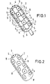
- FIGS. 1 to 3 Details of FIGS. 1 to 3 are shown in the illustration two possible configurations of the measuring probe according to the invention and the method according to the invention:
- FIG. 1 shows a top view of a cylindrical measuring probe 1, whose front and rear ends are rounded.
- Probe surface 2 On the Probe surface 2 is a multiplicity of point electrodes 3 arranged regularly, i.e. at the same distance from each other, each point electrode 3 surrounds an insulation ring 4, the is in turn enclosed by a ground ring 5, which is concentric arranged to the point electrode 3.
- the point electrodes 3 and the earth rings 5 are made of gold.
- the individual earth rings 5 are connected by means of lines 6, the point electrodes 3 individually connected.
- a connection cable 7 provides the connection of external units not shown in this figure with the probe 1.
- the measuring probe 1 shown in FIG. 2 is essentially corresponding the measuring probe designed according to Figure 1, it has their probe surface 2 point electrodes 3 and surrounding them Isolation rings 4 on. Instead of the earth rings 5 there has the remaining probe surface located between the insulation rings 4 8 a conductive ground surface. This as well as the Point electrodes are made of gold. Unlike that The embodiment according to FIG. 1 is an evaluation and storage unit for the determined measured values housed in the measuring probe 1. The values are displayed after removal of probe 1 the body opening.
- FIG. 3 shows a block diagram for heat detection, for example to detect the heat in cows.
- About one Multiplexers 10 become the number of point electrodes 3 corresponding impedance channels 11, for example sixteen Transfer impedance channels to an A / D converter 12.
- ALU arithmetic unit
- a serial Interface either feeds a short RF transmission link or an inductive transmission 16.
- An external reader receives the memory content daily and evaluates the data Heat detection off. Character for the heat is a clear one Drop in the impedance curve from approx. 60 ohms to approx. 10 to 20 ohms, which basically correspond to the temperature curve of the animal runs.
- a power saving circuit should be provided in order to Operation of the circuit for thirty-five days ensure.
- the entire circuit consists of several components:
- Sensor, ASIC and telemetry range should be miniaturized be built up so that an introduction to the vagina of cattle is possible.
- the full size should be of the sensor matched to the respective sheath configuration be.
- the measuring probe consists of physiologically harmless Material.
Landscapes
- Health & Medical Sciences (AREA)
- Life Sciences & Earth Sciences (AREA)
- Surgery (AREA)
- Animal Behavior & Ethology (AREA)
- Biomedical Technology (AREA)
- Heart & Thoracic Surgery (AREA)
- Medical Informatics (AREA)
- Molecular Biology (AREA)
- Pathology (AREA)
- Engineering & Computer Science (AREA)
- General Health & Medical Sciences (AREA)
- Public Health (AREA)
- Veterinary Medicine (AREA)
- Investigating Or Analyzing Materials By The Use Of Electric Means (AREA)
- Measurement And Recording Of Electrical Phenomena And Electrical Characteristics Of The Living Body (AREA)
- Measuring And Recording Apparatus For Diagnosis (AREA)
- Measurement Of Resistance Or Impedance (AREA)
- Investigating Or Analysing Biological Materials (AREA)
Description
- Gemischt analag/digitales-ASIC:
- Verstärker, Multiplexer, A/D-Wandler, Alu-Einheit (Logik Gatter), RAM
- Diskrete Technik:
- Induktive Übertragung bzw. HF-Sender
- bestehend aus:
- Empfangsteil (induktiv bzw. HF), µ-Prozessor, Langzeitspeicher, Ein-Ausgabeeinheiten
Claims (12)
- Verfahren zur Messung der elektrischen Leitfähigkeit von Zervical- und/oder Vaginalschleim unter Verwendung mehrerer, an unterschiedlichen Meßorten einer Körperstelle angebrachten Meßelektroden zum Zweck der Ermittlung von elektrischen Widerstandswerten, wobei die Messung mit Wechselstrom mittels einer die Meßelektroden aufweisenden Meßsonde erfolgt, wobei ferner die von den Meßelektroden jeweils ermittelten Widerstandswerte abgefragt und der geringste Widerstandswert als Bezugsgröße für die Bestimmung der elektrischen Leitfähigkeit ausgewertet wird.
- Verfahren nach Anspruch 1, wobei mittels der Meßelektroden eine punktuelle Messung erfolgt.
- Verfahren nach Anspruch 1 oder 2, wobei die Messung der Leitfähigkeit als Dauermessung in definierten Meßabständen erfolgt.
- Verfahren nach Anspruch 3, wobei die Meßabstände eine viertel, halbe oder eine Minute betragen.
- Verfahren nach einem der Ansprüche 1 bis 4, wobei die Messung mittels der die Meßelektroden aufweisenden Meßsonde in der Zervix/Vagina zum Zwecke der Brunsterkennung bzw. Bestimmung des Eisprunges erfolgt.
- Verfahren nach Anspruch 5, wobei sich das Ergebnis der Messung als Absolutbetrag der Impedanz darstellt.
- Verfahren nach einem der Ansprüche 1 bis 6, wobei zusätzlich zur Leitfähigkeit des Zervical- und/oder Vaginalschleimes Ionenabsonderungen in den Schleimen und/oder die Körpertemperaturen ermittelt werden.
- Meßsonde zur Durchführung des Verfahrens nach einem der Ansprüche 1 bis 7, wobei eine größere Anzahl von Punktelektroden (3) auf der Sondenoberfläche (2) verteilt angeordnet sind und den Punktelektroden eine gemeinsame Masse (5, 8) zugeordnet ist, derart, daß konzentrisch zur jeweiligen Punktelektrode (3) ein leitender Massering (5) angeordnet ist, sowie zwischen dem aus der Punktelektrode (3) und dem zugeordneten Massering (5) gebildeten Elektrodenpaar ein Isolationsring (4) angeordnet ist.
- Meßsonde zur Durchführung des Verfahrens nach einem der Ansprüche 1 bis 7, wobei eine größere Anzahl von Punktelektroden (3) auf der Sondenoberfläche (2) verteilt angeordnet sind und den Punktelektroden eine gemeinsame Masse (5, 8) zugeordnet ist, derart, daß um die jeweilige Punktelektrode (3) ein Isolationsring (4) angeordnet ist und die restliche Sondenoberfläche (8) eine leitende Masseoberfläche aufweist.
- Meßsonde nach einem der Ansprüche 8 oder 9, wobei die Punktelektroden (3) und die Masseringe (5) bzw. Masseoberfläche (8) aus nichtoxidierendem, leitfähigem Material, insbesondere Gold bestehen.
- Meßsonde nach einem der Ansprüche 8 bis 10, wobei diese zylindrisch mit abgerundeten Enden oder als Kugel ausgebildet ist.
- Meßsonde nach einem der Ansprüche 8 bis 11, wobei diese ionensensitive Elektroden und/oder Temperaturelektroden aufweist.
Applications Claiming Priority (3)
| Application Number | Priority Date | Filing Date | Title |
|---|---|---|---|
| DE4137303 | 1991-11-13 | ||
| DE4137303A DE4137303C2 (de) | 1991-11-13 | 1991-11-13 | Verfahren zur Messung der elektrischen Leitfähigkeit von Körperflüssigkeiten, sowie hierbei verwandte Meßsonde |
| PCT/EP1992/002573 WO1993009716A1 (de) | 1991-11-13 | 1992-11-10 | Verfahren zur messung der elektrischen leitfähigkeit von körperflüssigkeiten, sowie hierbei verwandte messonde |
Publications (2)
| Publication Number | Publication Date |
|---|---|
| EP0613348A1 EP0613348A1 (de) | 1994-09-07 |
| EP0613348B1 true EP0613348B1 (de) | 1998-01-21 |
Family
ID=6444699
Family Applications (1)
| Application Number | Title | Priority Date | Filing Date |
|---|---|---|---|
| EP92923288A Expired - Lifetime EP0613348B1 (de) | 1991-11-13 | 1992-11-10 | Verfahren zur messung der elektrischen leitfähigkeit von zervical- und/oder vaginalschleim, sowie hierbei verwandte messonde |
Country Status (11)
| Country | Link |
|---|---|
| US (1) | US5499631A (de) |
| EP (1) | EP0613348B1 (de) |
| JP (1) | JPH07500986A (de) |
| CN (1) | CN1044855C (de) |
| AU (1) | AU667693B2 (de) |
| BR (1) | BR9206715A (de) |
| CA (1) | CA2123398A1 (de) |
| DE (2) | DE4137303C2 (de) |
| ES (1) | ES2113961T3 (de) |
| RU (1) | RU2113173C1 (de) |
| WO (1) | WO1993009716A1 (de) |
Families Citing this family (28)
| Publication number | Priority date | Publication date | Assignee | Title |
|---|---|---|---|---|
| US6149591A (en) * | 1997-02-21 | 2000-11-21 | Duke University | Refractometric devices especially adapted for the in vivo detection of refractive indices of cervical mucus |
| AU2318599A (en) | 1998-01-13 | 1999-08-02 | Urometrics, Inc. | Devices and methods for monitoring female arousal |
| IL126723A0 (en) * | 1998-10-22 | 1999-08-17 | Medoc Ltd | Vaginal probe and method |
| US6080118A (en) * | 1999-02-25 | 2000-06-27 | Blythe; Cleveland | Vaginal probe and method of using same |
| JP3713407B2 (ja) | 1999-09-13 | 2005-11-09 | 株式会社タニタ | 婦人用体調管理装置 |
| US6901884B1 (en) * | 1999-09-29 | 2005-06-07 | Abel Jacobus Rautenbach | Immobilization device |
| US7729756B2 (en) | 2000-01-18 | 2010-06-01 | Siemens Aktiengesellschaft | Measurement system for examining a section of tissue on a patient and the use of a measurement system of this type |
| US6461308B1 (en) * | 2001-03-13 | 2002-10-08 | Probe Diagnostics, Inc. | Apparatus for detecting the presence of pathology |
| US6461309B1 (en) * | 2001-03-13 | 2002-10-08 | Probe Diagnostics, Inc. | Apparatus for detecting the presence of pathology |
| AT411215B (de) * | 2001-04-25 | 2003-11-25 | Nova Technical Res Gmbh | Verfahren und einrichtung zur bestimmung des weiblichen hormonstatus |
| US20050049518A1 (en) * | 2001-11-12 | 2005-03-03 | Nel Andre Johan | Determining progresterone cycles in livestock |
| GB0206260D0 (en) * | 2002-03-16 | 2002-05-01 | Univ Bristol | Thermometer |
| CN1316941C (zh) * | 2004-07-01 | 2007-05-23 | 姜枫 | 一种生物电阻率人体体液平衡监测仪器及监测方法 |
| US20080071190A1 (en) * | 2004-08-31 | 2008-03-20 | Gorodeski George I | Timing of Ovulation Based on Vaginal Ph |
| US7183779B2 (en) * | 2004-12-28 | 2007-02-27 | Spectrum Technologies, Inc. | Soil probe device and method of making same |
| RU2303394C2 (ru) * | 2005-05-30 | 2007-07-27 | Федеральное государственное унитарное предприятие Омский научно-исследовательский институт приборостроения | Способ исследования состояния шейки матки у женщин и устройство для его осуществления |
| FR2895667B3 (fr) * | 2006-01-05 | 2008-04-04 | Rene Vinci | Detecteur de fecondite pour mammiferes |
| RU2380026C1 (ru) * | 2008-09-23 | 2010-01-27 | Марсель Фаикович Самигуллин | Способ зондирования полого органа и устройство для его осуществления |
| ES2562264T5 (es) * | 2010-05-25 | 2019-06-24 | Arc Medical Design Ltd | Cubierta para dispositivo médico de exploración |
| US10517667B2 (en) | 2014-05-16 | 2019-12-31 | Biosense Webster (Israel) Ltd. | Catheter tip with microelectrodes |
| US8593251B2 (en) * | 2011-06-16 | 2013-11-26 | Alan Camerik Heller | Systems for detecting a febrile condition and reducing risks of spreading infection |
| US8686863B2 (en) * | 2011-06-16 | 2014-04-01 | Alan C. Heller | System and process for detecting a febrile condition |
| US12239419B2 (en) | 2011-11-04 | 2025-03-04 | Alan C. Heller | Systems for real time febrility detection and notification |
| CN104622514B (zh) * | 2015-02-27 | 2018-04-10 | 江苏矽望电子科技有限公司 | 一种基于双传感器的排卵测试系统及方法 |
| CN104622515B (zh) * | 2015-02-27 | 2017-05-17 | 江苏矽望电子科技有限公司 | 体液导电性传感器 |
| CN106137263B8 (zh) * | 2016-07-25 | 2025-05-30 | 南京小鲸鲨信息科技有限公司 | 一种基于云端分析技术的排卵测定仪及其测定方法 |
| US11172984B2 (en) | 2019-05-03 | 2021-11-16 | Biosense Webster (Israel) Ltd. | Device, system and method to ablate cardiac tissue |
| JP7237320B1 (ja) * | 2022-06-24 | 2023-03-13 | 株式会社Recotek | センサー |
Family Cites Families (9)
| Publication number | Priority date | Publication date | Assignee | Title |
|---|---|---|---|---|
| US3844276A (en) * | 1973-07-19 | 1974-10-29 | J Mcdougall | Probe and method for detecting estrus in animals |
| US4224949A (en) * | 1977-11-17 | 1980-09-30 | Cornell Research Foundation, Inc. | Method and electrical resistance probe for detection of estrus in bovine |
| DE2941363C2 (de) * | 1979-10-12 | 1985-08-22 | Deutsche Forschungs- und Versuchsanstalt für Luft- und Raumfahrt e.V., 5000 Köln | Gerät zur Bestimmung von Eigenschaften lebender Gewebe |
| US4498481A (en) * | 1982-09-28 | 1985-02-12 | Lemke Judith K | Estrus cycle monitoring system |
| US4685471A (en) * | 1984-09-11 | 1987-08-11 | Zetek, Inc. | Method and apparatus for predicting and detecting the onset of ovulation |
| US4690152A (en) * | 1985-10-23 | 1987-09-01 | American Mediscan, Inc. | Apparatus for epithelial tissue impedance measurements |
| US4784155A (en) * | 1987-07-17 | 1988-11-15 | Data Sciences, Inc. | Device for automated detection of estrus in farm animals |
| JPH01126535A (ja) * | 1987-11-12 | 1989-05-18 | Kao Corp | 皮膚水分含有量の測定方法および装置 |
| DE3836349A1 (de) * | 1988-10-25 | 1990-05-03 | Forschungsgesellschaft Fuer Bi | Katheter zur messung von motilitaet und peristaltik in schlauchfoermigen, ihren inhalt transportierenden organen mittels simultaner multipler impedanzmessung |
-
1991
- 1991-11-13 DE DE4137303A patent/DE4137303C2/de not_active Expired - Fee Related
-
1992
- 1992-11-10 US US08/244,035 patent/US5499631A/en not_active Expired - Fee Related
- 1992-11-10 EP EP92923288A patent/EP0613348B1/de not_active Expired - Lifetime
- 1992-11-10 CA CA002123398A patent/CA2123398A1/en not_active Abandoned
- 1992-11-10 AU AU29247/92A patent/AU667693B2/en not_active Ceased
- 1992-11-10 ES ES92923288T patent/ES2113961T3/es not_active Expired - Lifetime
- 1992-11-10 WO PCT/EP1992/002573 patent/WO1993009716A1/de not_active Ceased
- 1992-11-10 JP JP5508945A patent/JPH07500986A/ja active Pending
- 1992-11-10 BR BR9206715A patent/BR9206715A/pt not_active Application Discontinuation
- 1992-11-10 DE DE59209154T patent/DE59209154D1/de not_active Expired - Fee Related
- 1992-11-10 RU RU94027293A patent/RU2113173C1/ru active
- 1992-11-12 CN CN92112249A patent/CN1044855C/zh not_active Expired - Fee Related
Also Published As
| Publication number | Publication date |
|---|---|
| JPH07500986A (ja) | 1995-02-02 |
| DE4137303C2 (de) | 1993-12-02 |
| BR9206715A (pt) | 1995-10-24 |
| RU94027293A (ru) | 1996-06-20 |
| CN1073350A (zh) | 1993-06-23 |
| DE4137303A1 (de) | 1993-05-27 |
| CN1044855C (zh) | 1999-09-01 |
| EP0613348A1 (de) | 1994-09-07 |
| CA2123398A1 (en) | 1993-05-27 |
| US5499631A (en) | 1996-03-19 |
| AU667693B2 (en) | 1996-04-04 |
| ES2113961T3 (es) | 1998-05-16 |
| AU2924792A (en) | 1993-06-15 |
| DE59209154D1 (de) | 1998-02-26 |
| RU2113173C1 (ru) | 1998-06-20 |
| WO1993009716A1 (de) | 1993-05-27 |
Similar Documents
| Publication | Publication Date | Title |
|---|---|---|
| EP0613348B1 (de) | Verfahren zur messung der elektrischen leitfähigkeit von zervical- und/oder vaginalschleim, sowie hierbei verwandte messonde | |
| DE68924058T2 (de) | Unterscheidende funktionale Analisierungsmethode und Gerät zur Krankheitsdiagnose und Darstellung. | |
| DE69505799T2 (de) | Elektrische impedanz-tomographie | |
| DE69526268T2 (de) | Ultraschall-Messgerät zur Bestimmung der Knochendichte und der Knochenstruktur | |
| DE69528628T2 (de) | Impedanz-Messgerät zum Gebrauch als Instrument zum Überwachen des Gesundheitszustandes | |
| DE69129698T2 (de) | Vorrichtung zur messung der elektrischen impedanz von organischen und biologischen stoffen | |
| DE60013661T2 (de) | Handgeführte Vorrichtung zur bioelektrischen Impedanzmessung | |
| DE3854372T2 (de) | Leitfähigkeits-Messanordnung. | |
| DE3203300A1 (de) | Implantierbare leitung | |
| DE60313218T2 (de) | System und verfahren zur dreidimensionalen visualisierung der leitfähigkeit und stromdichteverteilung in einem elektrisch leitenden objekt | |
| DE3623711A1 (de) | Vorrichtung zum feststellen von eigenschaften, verschiedenheiten und veraenderungen des menschlichen oder tierischen koerpers | |
| DE69632645T2 (de) | Vorrichtung und verfahren zur bestimmung des fruchtbarkeitsstatus von frauen | |
| DE60034518T2 (de) | Entscheidungsfindugsgerät für die monatliche physiologische Kondition eines weiblichen Körpers | |
| DE10309245A1 (de) | Vorrichtung zum Lokalisieren einer fokalen Läsion in einem biologischen Gewebeabschnitt | |
| DE69728065T2 (de) | Vorrichtung zum nachweis von karies | |
| DE3342251A1 (de) | Verfahren zur messung der koerpertemperatur von menschen und tieren, insbesondere fuer die bestimmung des eisprungs | |
| DE2107114A1 (de) | Verfahren und Gerat zum elektrischen Messen der Dicke von Speck und Fleisch schichten im Korper geschlachteter Tiere | |
| US5217022A (en) | Electrical impedance imaging to monitor myometrial activity | |
| AT411215B (de) | Verfahren und einrichtung zur bestimmung des weiblichen hormonstatus | |
| Sato et al. | Variations in motor evoked potential latencies in the anal sphincter system with sacral magnetic stimulation | |
| DD221635A1 (de) | Vorrichtung zur messung und bewertung physiologischer parameter bei weiblichen saeugetieren | |
| DE20110961U1 (de) | Vorrichtung zum Messen des menschlichen Körperfetts | |
| DE102020207417A1 (de) | Verfahren und Vorrichtung zur Bestimmung der Körperkerntemperatur mittels Bioimpedanzmessung | |
| Rowinski et al. | Correlation of peripheral receptive field area and rostrocaudal locus of neurons within the raccoon cuneate nucleus | |
| DE2326029A1 (de) | Geraet zur ovulationsueberwachung |
Legal Events
| Date | Code | Title | Description |
|---|---|---|---|
| PUAI | Public reference made under article 153(3) epc to a published international application that has entered the european phase |
Free format text: ORIGINAL CODE: 0009012 |
|
| 17P | Request for examination filed |
Effective date: 19940510 |
|
| AK | Designated contracting states |
Kind code of ref document: A1 Designated state(s): CH DE ES FR GB IE IT LI NL |
|
| 17Q | First examination report despatched |
Effective date: 19951031 |
|
| RAP1 | Party data changed (applicant data changed or rights of an application transferred) |
Owner name: RHEINTECHNIK WEILAND & KASPAR GMBH & CO KG .MASCHI |
|
| GRAG | Despatch of communication of intention to grant |
Free format text: ORIGINAL CODE: EPIDOS AGRA |
|
| GRAG | Despatch of communication of intention to grant |
Free format text: ORIGINAL CODE: EPIDOS AGRA |
|
| GRAH | Despatch of communication of intention to grant a patent |
Free format text: ORIGINAL CODE: EPIDOS IGRA |
|
| GRAH | Despatch of communication of intention to grant a patent |
Free format text: ORIGINAL CODE: EPIDOS IGRA |
|
| GRAA | (expected) grant |
Free format text: ORIGINAL CODE: 0009210 |
|
| AK | Designated contracting states |
Kind code of ref document: B1 Designated state(s): CH DE ES FR GB IE IT LI NL |
|
| REG | Reference to a national code |
Ref country code: CH Ref legal event code: EP |
|
| REF | Corresponds to: |
Ref document number: 59209154 Country of ref document: DE Date of ref document: 19980226 |
|
| REG | Reference to a national code |
Ref country code: CH Ref legal event code: NV Representative=s name: ISLER & PEDRAZZINI AG |
|
| GBT | Gb: translation of ep patent filed (gb section 77(6)(a)/1977) |
Effective date: 19980302 |
|
| ITF | It: translation for a ep patent filed | ||
| ET | Fr: translation filed | ||
| REG | Reference to a national code |
Ref country code: ES Ref legal event code: FG2A Ref document number: 2113961 Country of ref document: ES Kind code of ref document: T3 |
|
| REG | Reference to a national code |
Ref country code: IE Ref legal event code: FG4D Free format text: 78511 |
|
| PLBE | No opposition filed within time limit |
Free format text: ORIGINAL CODE: 0009261 |
|
| STAA | Information on the status of an ep patent application or granted ep patent |
Free format text: STATUS: NO OPPOSITION FILED WITHIN TIME LIMIT |
|
| 26N | No opposition filed | ||
| PGFP | Annual fee paid to national office [announced via postgrant information from national office to epo] |
Ref country code: GB Payment date: 20011012 Year of fee payment: 10 |
|
| PGFP | Annual fee paid to national office [announced via postgrant information from national office to epo] |
Ref country code: CH Payment date: 20011016 Year of fee payment: 10 |
|
| PGFP | Annual fee paid to national office [announced via postgrant information from national office to epo] |
Ref country code: IE Payment date: 20011018 Year of fee payment: 10 |
|
| PGFP | Annual fee paid to national office [announced via postgrant information from national office to epo] |
Ref country code: NL Payment date: 20011031 Year of fee payment: 10 |
|
| PGFP | Annual fee paid to national office [announced via postgrant information from national office to epo] |
Ref country code: FR Payment date: 20011106 Year of fee payment: 10 |
|
| PGFP | Annual fee paid to national office [announced via postgrant information from national office to epo] |
Ref country code: ES Payment date: 20011119 Year of fee payment: 10 |
|
| PGFP | Annual fee paid to national office [announced via postgrant information from national office to epo] |
Ref country code: DE Payment date: 20011228 Year of fee payment: 10 |
|
| REG | Reference to a national code |
Ref country code: GB Ref legal event code: IF02 |
|
| PG25 | Lapsed in a contracting state [announced via postgrant information from national office to epo] |
Ref country code: GB Free format text: LAPSE BECAUSE OF NON-PAYMENT OF DUE FEES Effective date: 20021110 |
|
| PG25 | Lapsed in a contracting state [announced via postgrant information from national office to epo] |
Ref country code: IE Free format text: LAPSE BECAUSE OF NON-PAYMENT OF DUE FEES Effective date: 20021111 Ref country code: ES Free format text: LAPSE BECAUSE OF NON-PAYMENT OF DUE FEES Effective date: 20021111 |
|
| PG25 | Lapsed in a contracting state [announced via postgrant information from national office to epo] |
Ref country code: LI Free format text: LAPSE BECAUSE OF NON-PAYMENT OF DUE FEES Effective date: 20021130 Ref country code: CH Free format text: LAPSE BECAUSE OF NON-PAYMENT OF DUE FEES Effective date: 20021130 |
|
| PG25 | Lapsed in a contracting state [announced via postgrant information from national office to epo] |
Ref country code: NL Free format text: LAPSE BECAUSE OF NON-PAYMENT OF DUE FEES Effective date: 20030601 |
|
| PG25 | Lapsed in a contracting state [announced via postgrant information from national office to epo] |
Ref country code: DE Free format text: LAPSE BECAUSE OF NON-PAYMENT OF DUE FEES Effective date: 20030603 |
|
| GBPC | Gb: european patent ceased through non-payment of renewal fee | ||
| REG | Reference to a national code |
Ref country code: CH Ref legal event code: PL |
|
| PG25 | Lapsed in a contracting state [announced via postgrant information from national office to epo] |
Ref country code: FR Free format text: LAPSE BECAUSE OF NON-PAYMENT OF DUE FEES Effective date: 20030731 |
|
| NLV4 | Nl: lapsed or anulled due to non-payment of the annual fee |
Effective date: 20030601 |
|
| REG | Reference to a national code |
Ref country code: IE Ref legal event code: MM4A |
|
| REG | Reference to a national code |
Ref country code: FR Ref legal event code: ST |
|
| REG | Reference to a national code |
Ref country code: ES Ref legal event code: FD2A Effective date: 20031213 |
|
| PG25 | Lapsed in a contracting state [announced via postgrant information from national office to epo] |
Ref country code: IT Free format text: LAPSE BECAUSE OF NON-PAYMENT OF DUE FEES;WARNING: LAPSES OF ITALIAN PATENTS WITH EFFECTIVE DATE BEFORE 2007 MAY HAVE OCCURRED AT ANY TIME BEFORE 2007. THE CORRECT EFFECTIVE DATE MAY BE DIFFERENT FROM THE ONE RECORDED. Effective date: 20051110 |