EP0613049A1 - Apparatus for the processing of sheet material - Google Patents
Apparatus for the processing of sheet material Download PDFInfo
- Publication number
- EP0613049A1 EP0613049A1 EP94200313A EP94200313A EP0613049A1 EP 0613049 A1 EP0613049 A1 EP 0613049A1 EP 94200313 A EP94200313 A EP 94200313A EP 94200313 A EP94200313 A EP 94200313A EP 0613049 A1 EP0613049 A1 EP 0613049A1
- Authority
- EP
- European Patent Office
- Prior art keywords
- rack
- liquid
- tank
- pump
- guide rollers
- Prior art date
- Legal status (The legal status is an assumption and is not a legal conclusion. Google has not performed a legal analysis and makes no representation as to the accuracy of the status listed.)
- Granted
Links
Images


Classifications
-
- G—PHYSICS
- G03—PHOTOGRAPHY; CINEMATOGRAPHY; ANALOGOUS TECHNIQUES USING WAVES OTHER THAN OPTICAL WAVES; ELECTROGRAPHY; HOLOGRAPHY
- G03D—APPARATUS FOR PROCESSING EXPOSED PHOTOGRAPHIC MATERIALS; ACCESSORIES THEREFOR
- G03D3/00—Liquid processing apparatus involving immersion; Washing apparatus involving immersion
- G03D3/08—Liquid processing apparatus involving immersion; Washing apparatus involving immersion having progressive mechanical movement of exposed material
- G03D3/13—Liquid processing apparatus involving immersion; Washing apparatus involving immersion having progressive mechanical movement of exposed material for long films or prints in the shape of strips, e.g. fed by roller assembly
- G03D3/132—Liquid processing apparatus involving immersion; Washing apparatus involving immersion having progressive mechanical movement of exposed material for long films or prints in the shape of strips, e.g. fed by roller assembly fed by roller assembly
-
- G—PHYSICS
- G03—PHOTOGRAPHY; CINEMATOGRAPHY; ANALOGOUS TECHNIQUES USING WAVES OTHER THAN OPTICAL WAVES; ELECTROGRAPHY; HOLOGRAPHY
- G03D—APPARATUS FOR PROCESSING EXPOSED PHOTOGRAPHIC MATERIALS; ACCESSORIES THEREFOR
- G03D3/00—Liquid processing apparatus involving immersion; Washing apparatus involving immersion
- G03D3/02—Details of liquid circulation
- G03D3/06—Liquid supply; Liquid circulation outside tanks
Definitions
- the present invention relates to an apparatus for the processing of sheet material, in particular film or other photo-chemical material.
- the sheet material is brought into contact with aqueous processing liquids, and rinsing water in a processing machine.
- reaction between the sheet material and the processing liquid takes place in a thin reaction zone or layer of the liquid close to the surface of the sheet material.
- active chemicals in the reaction zone become used up and this zone becomes saturated with reaction products. It is necessary for fresh active chemicals to diffuse into this zone from the bulk of the liquid and for the reaction products to diffuse away.
- circulation of the processing liquid is often employed.
- a processing machine there is an open-topped tank divided into a number of compartments, in each of which is located a removable rack.
- Each rack has opposite side plates carrying at least one pair of guide rollers to define a transport path for the sheet material.
- a number of liquid inlet openings are provided in one side plate, and a number of liquid outlet openings are provided in the opposite side plate.
- the side plates of the rack are spaced from the sides of the tank to form there-between a liquid inlet well on one side and a liquid outlet well on the other.
- a pump feeds processing liquid to the liquid inlet well and withdraws processing liquid from the outlet well. Processing liquid circulates through the rack under pressure of the small liquid head in the inlet well.
- Processing machines may adopt so-called rinsing chambers in which liquid spray devices are provided to direct processing liquid directly onto the sheet material from above and below, but such machines are complicated and costly to manufacture.
- an apparatus for the processing of sheet material comprising a tank and at least one removable rack located in said tank, each rack having opposite side plates, a liquid inlet opening in one side plate, a liquid outlet opening in the opposite side plate, and a pump for feeding processing liquid to and from the tank to circulate the processing liquid through the rack, characterised in that the output side of the pump is in liquid communication with the liquid inlet opening to feed processing liquid under pressure of the pump into the rack.
- the invention enables the construction of processing machines which provide good circulation without the use of high flow-rate pumps and without the use of rinsing chambers.
- the racks can still be of small design.
- the use of an external pump is preferred, although a pump located in the tank is also possible.
- the pump may have a capacity of from 1 to 5 l/min.
- the total cross-sectional area of the outlet openings is at least as large as that of the inlet openings, thereby to reduce the risk of overflowing.
- the inlet openings may be relatively wide, to limit back pressure and reduce the possibility of turbulence being generated as the processing liquid passes through the inlet openings.
- the output side of the pump is in liquid communication with releasable connection means and the rack includes pipe-work leading from the liquid inlet opening to the releasable connection means.
- the releasable connection means may be comprised by an upwardly facing connection port in the tank in liquid communication with the output side of the pump and a downwardly directed pipe end of the rack pipe-work, engageable in the upwardly facing connection port.
- the rack pipe-work leading to the liquid inlet opening includes at least one elbow.
- the transport path may be further defined by one or more guide plates and/or by at least a second pair of guide rollers.
- the transport path may be defined by an entry pair of guide rollers, an exit pair of guide rollers and at least one intermediate pair of guide rollers.
- Guide plates may be located between each pair of guide rollers and liquid inlet openings in the side plate are preferably positioned adjacent these guide plates to direct liquid over the upper surface of the sheet material as it passes over the guide plates.
- the pipework is located outside the tank and includes one or more open-ended tank-based pipes which pass through the wall of the tank, opening into the inlet well.
- the side wall of the rack carries horizontally disposed open-ended rack-based pipes extending from the inlet apertures into the inlet well towards the side of the tank, opening in close proximity to the open ends of the tank-based pipes.
- Processing liquid fed by the pump passes from the tank-based pipes into the rack-based pipes and thence to the inlet apertures and into the rack.
- the connection between the pipes is not liquid-tight, the close proximity thereof is sufficient to ensure that the liquid pressure generated by the pump is substantially used to generate the required circulation of processing liquid through the rack. This arrangement enables the rack to be simply lifted out of the tank, for cleaning purposes, without the need to make any disconnections.
- an apparatus for the processing of sheet material comprises an open-topped tank 10 divided into a number of compartments 11a, 11b etc by cross walls 13 extending between the side walls 21 of the tank 10.
- each compartment 11 there is located one of a number of identical removable racks 12a, 12b etc., only rack 12c in compartment 11c being shown in Figure 1 for the sake of clarity.
- Each compartment has a width of about 80 cm, a length of about 13 cm and a depth of about 7 cm.
- Each compartment 11 therefore has a liquid capacity of about 8 litres excluding the rack.
- Each rack 12 is formed with opposite side plates 14a, 14b which are spaced from the sides of the respective compartment 11 so as two form on each side a well, designated as an inlet well 17a and an outlet well 17b, each having a capacity of about 0.7 litres.
- a sheet material transport path 15 is defined by an entry pair of guide rollers 16a, 16b, an exit pair of guide rollers 18a, 18b, and an intermediate pair of guide rollers 20a, 20b.
- the guide rollers have a width of 72 cm, are supported between the side plates 14a, 14b and are arranged with their axes parallel, at right angles to the transport path 15.
- the transport path is further defined by two curved guide plates 22a, 22b.
- the rack 12 includes pipe-work 32 leading from the liquid inlet openings to a downwardly directed pipe end 36.
- the pipe-work 32 leads from the downwardly directed pipe end 36 to the two liquid inlet openings via a T-junction 38 which splits the liquid flow into two paths, an elbow 40 having an angle of about 90° being provided in each path.
- processing liquid fills the tank compartment 11 to a level 27 at or above the uppermost of the guide rollers 16, 18, 20, filling not only the rack 12 but also the inlet and outlet wells 17a, 17b.
- the output side 30 of a pump 28 located below the tank 10 is in liquid communication with an upwardly facing connection port 34 in the tank 10 to form a releasable connection between the rack pipe-work 32 and the pump 28.
- the pump 28 has a capacity of 5 l/min and feeds processing liquid at a pressure of 100 cm water via the liquid inlet openings 24a, 24b into the rack 12. Processing liquid leaves the rack 12 through the outlet openings 26a, 26b into the outlet well 17b thereby enabling the processing liquid to circulate through the rack 12.
- the liquid inlet openings 24a, 24b and the liquid outlet openings 26a, 26b are so positioned to provide a circulating flow of the processing liquid closely adjacent the surface of the sheet material across the transport path in a direction parallel to the guide rollers 16, 18, 20 as indicated by the line 25 in Figure 3.
- the pump 28 withdraws processing liquid from the outlet well 17b by way of a flexible pipe 44.
- connection port 34 is formed by a plastics material bush 35 inserted in an aperture 37 formed in the base 23 of the tank 10.
- the bush has an upwardly directed bevelled face 39 on which the lower end 36 of the pipework 32 rests.
- the bush 35 is extended in a downwards direction into a sleeve 41 onto which a flexible pipe 43 is fitted and secured by means not shown.
- the connection between the lower end 36 of the pipework 32 and the upwardly directed face 39 of the bush 35 need not be absolutely liquid-tight. Any processing liquid leaking at this connection passes into the inlet well 17a, which already contains processing liquid at the same level as in the rack 12 and the outlet well 17b.
- a worm drive 19 is located in the tank 10, driven by means not shown, and carries worms 191, 192 which, when the rack is in position, engage with worm gears 511 and 512 respectively, carried on the axles of the rollers 16b, 18b on the outside of the side wall 14b.
- the worm gears 511, 512 mesh with gear wheels 513, 514 which are carried on the axles of the rollers 16a, 16b.
- An intermediate gear wheel 515 also carried on the outside of the side wall 14b, transfers the drive to the guide rollers 20a, 20b via meshing gear wheels 516, 517.
- Operation of the worm drive 19 thereby causes rotation of the rollers 16, 18, 20 to drive the sheet through the processing liquid in the rack.
- the drive means cause the sheet material to be transported through the rack 12 at a linear speed of 30 to 120 cm/min, giving a residence time within the processing liquid of about 40 to 6 seconds.
- Guide means are provided to guide the sheet material from one rack to the next, thereby causing the sheet material to be dipped successively in the processing liquids of all the racks.
- the compartments 11a, 11b etc will usually be provided with different processing liquids, such as in sequence, a developing liquid, a fixing liquid and one or more rinsing liquids.
- the height of the cross walls 13 is such as to limit overflow of processing liquid from one compartment to the next.
- Each side plate 14a, 14b is provided with a handle 42a, 42b, which permit the user to remove the rack 12 from the tank 10 in a convenient manner for cleaning purposes.
- the pipework 32 is located outside the tank 10, and is in fluid-tight connection with the flexible pipe 43 from the pump 28.
- the pipework includes open-ended pipes 53 which pass through the wall of the tank 10, opening into the inlet well 17a.
- the side wall 14a of the rack 12 carries horizontally disposed open-ended pipes 55 extending from the inlet apertures 24 towards the side of the tank 10. The arrangement is such that, when the rack 12 is in position in the tank 10 the open ends of the pipes 53 and 55 are in close proximity to each other. Processing liquid fed by the pump 28 passes from the pipes 53 into the pipes 55 and thence to the inlet apertures 24 and into the rack 12.
- connection between the pipes 53 and 55 is not liquid-tight, the close proximity thereof is sufficient to ensure that the liquid pressure generated by the pump 28 is Substantially used to generate the required circulation of processing liquid through the rack.
- This arrangement enables the rack 12 to be simply lifted out of the tank 10, for cleaning purposes, without the need to make any disconnections.
Abstract
Description
- The present invention relates to an apparatus for the processing of sheet material, in particular film or other photo-chemical material. In such a process the sheet material is brought into contact with aqueous processing liquids, and rinsing water in a processing machine.
- The reaction between the sheet material and the processing liquid takes place in a thin reaction zone or layer of the liquid close to the surface of the sheet material. As the reaction proceeds, active chemicals in the reaction zone become used up and this zone becomes saturated with reaction products. It is necessary for fresh active chemicals to diffuse into this zone from the bulk of the liquid and for the reaction products to diffuse away. To achieve this continuous refreshment of the reaction zone, circulation of the processing liquid is often employed.
- In a known processing machine there is an open-topped tank divided into a number of compartments, in each of which is located a removable rack. Each rack has opposite side plates carrying at least one pair of guide rollers to define a transport path for the sheet material. A number of liquid inlet openings are provided in one side plate, and a number of liquid outlet openings are provided in the opposite side plate. The side plates of the rack are spaced from the sides of the tank to form there-between a liquid inlet well on one side and a liquid outlet well on the other. A pump feeds processing liquid to the liquid inlet well and withdraws processing liquid from the outlet well. Processing liquid circulates through the rack under pressure of the small liquid head in the inlet well.
- There is a need for a variety of reasons to employ processing apparatus which is as small as possible and which uses as small a volume of processing liquid as possible. Thus while volumes of processing liquid such as 24 l/m² of sheet material were used in earlier devices, volumes as low as 0.25 l/m² are now desirable, generating a need for even more effective refreshment of the reaction zone. While this may be achieved by increasing circulation rates, it is essential that the refreshment of the reaction zone is as uniform as possible over the width of the sheet, otherwise inconsistent processing results. If, in the type of processing apparatus referred to above, the pump pressure was to be increased, high flow rates through the rack might be achieved, but not without the generation of turbulence. Too much turbulence, and/or the generation of waves can lead to overflowing of liquid from the tank. Processing machines may adopt so-called rinsing chambers in which liquid spray devices are provided to direct processing liquid directly onto the sheet material from above and below, but such machines are complicated and costly to manufacture.
- We have now discovered that advantages can be achieved if, in the type of processing apparatus referred to above, the output side of the pump is in liquid communication with the liquid inlet opening to feed processing liquid under pressure of the pump into the rack.
- Thus, according to the invention there is provided an apparatus for the processing of sheet material, comprising a tank and at least one removable rack located in said tank, each rack having opposite side plates, a liquid inlet opening in one side plate, a liquid outlet opening in the opposite side plate, and a pump for feeding processing liquid to and from the tank to circulate the processing liquid through the rack, characterised in that the output side of the pump is in liquid communication with the liquid inlet opening to feed processing liquid under pressure of the pump into the rack.
- The invention enables the construction of processing machines which provide good circulation without the use of high flow-rate pumps and without the use of rinsing chambers. The racks can still be of small design.
- The use of an external pump is preferred, although a pump located in the tank is also possible. The pump may have a capacity of from 1 to 5 l/min.
- It is desirable that the total cross-sectional area of the outlet openings is at least as large as that of the inlet openings, thereby to reduce the risk of overflowing. The inlet openings may be relatively wide, to limit back pressure and reduce the possibility of turbulence being generated as the processing liquid passes through the inlet openings.
- In a preferred embodiment of the invention, the output side of the pump is in liquid communication with releasable connection means and the rack includes pipe-work leading from the liquid inlet opening to the releasable connection means.
- The releasable connection means may be comprised by an upwardly facing connection port in the tank in liquid communication with the output side of the pump and a downwardly directed pipe end of the rack pipe-work, engageable in the upwardly facing connection port. The rack pipe-work from the downwardly directed pipe end to at least one liquid inlet opening provided in the same side plate. Preferably, the rack pipe-work leading to the liquid inlet opening includes at least one elbow.
- The transport path may be further defined by one or more guide plates and/or by at least a second pair of guide rollers. In particular, the transport path may be defined by an entry pair of guide rollers, an exit pair of guide rollers and at least one intermediate pair of guide rollers. Guide plates may be located between each pair of guide rollers and liquid inlet openings in the side plate are preferably positioned adjacent these guide plates to direct liquid over the upper surface of the sheet material as it passes over the guide plates.
- In an alternative embodiment of the invention, the pipework is located outside the tank and includes one or more open-ended tank-based pipes which pass through the wall of the tank, opening into the inlet well. The side wall of the rack carries horizontally disposed open-ended rack-based pipes extending from the inlet apertures into the inlet well towards the side of the tank, opening in close proximity to the open ends of the tank-based pipes. Processing liquid fed by the pump passes from the tank-based pipes into the rack-based pipes and thence to the inlet apertures and into the rack. Although the connection between the pipes is not liquid-tight, the close proximity thereof is sufficient to ensure that the liquid pressure generated by the pump is substantially used to generate the required circulation of processing liquid through the rack. This arrangement enables the rack to be simply lifted out of the tank, for cleaning purposes, without the need to make any disconnections.
- The invention will now be further described, purely by way of example, by reference to the accompanying drawings in which:
- Figure 1 shows a general view of an apparatus according to the invention;
- Figure 2A shows one end of one of the racks used in the apparatus shown in Figure 1;
- Figure 2B shows the other end of the rack shown in Figure 2A;
- Figure 2C shows, diagramatically, a view in the direction IIC in Figure 2B;
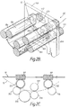
- Figure 3 shows a vertical cross-section of the apparatus shown in Figure 1;
- Figure 4 shows in more detail part of the view shown in Figure 3; and
- Figure 5 is a view, similar to Figure 3, of an alternative embodiment of the invention.
- Referring to Figure 1, an apparatus for the processing of sheet material comprises an open-
topped tank 10 divided into a number ofcompartments cross walls 13 extending between theside walls 21 of thetank 10. In each compartment 11, there is located one of a number of identical removable racks 12a, 12b etc., onlyrack 12c in compartment 11c being shown in Figure 1 for the sake of clarity. Each compartment has a width of about 80 cm, a length of about 13 cm and a depth of about 7 cm. Each compartment 11 therefore has a liquid capacity of about 8 litres excluding the rack. Eachrack 12 is formed withopposite side plates - As can be seen in Figures 2A and 2B, a sheet
material transport path 15 is defined by an entry pair ofguide rollers 16a, 16b, an exit pair ofguide rollers guide rollers side plates transport path 15. The transport path is further defined by twocurved guide plates liquid outlet openings 26a, 26b each having a cross-sectional area of 2 cm² are found in corresponding positions in theopposite side plate 14b. Therack 12 includes pipe-work 32 leading from the liquid inlet openings to a downwardly directedpipe end 36. The pipe-work 32 leads from the downwardly directedpipe end 36 to the two liquid inlet openings via a T-junction 38 which splits the liquid flow into two paths, anelbow 40 having an angle of about 90° being provided in each path. - As can be seen from Figure 3, processing liquid fills the tank compartment 11 to a
level 27 at or above the uppermost of the guide rollers 16, 18, 20, filling not only therack 12 but also the inlet andoutlet wells output side 30 of apump 28 located below thetank 10 is in liquid communication with an upwardly facingconnection port 34 in thetank 10 to form a releasable connection between the rack pipe-work 32 and thepump 28. Thepump 28 has a capacity of 5 l/min and feeds processing liquid at a pressure of 100 cm water via the liquid inlet openings 24a, 24b into therack 12. Processing liquid leaves therack 12 through theoutlet openings 26a, 26b into theoutlet well 17b thereby enabling the processing liquid to circulate through therack 12. The liquid inlet openings 24a, 24b and theliquid outlet openings 26a, 26b are so positioned to provide a circulating flow of the processing liquid closely adjacent the surface of the sheet material across the transport path in a direction parallel to the guide rollers 16, 18, 20 as indicated by theline 25 in Figure 3. Thepump 28 withdraws processing liquid from theoutlet well 17b by way of aflexible pipe 44. - As can be seen more clearly in Figure 4, the
connection port 34 is formed by aplastics material bush 35 inserted in anaperture 37 formed in thebase 23 of thetank 10. The bush has an upwardly directedbevelled face 39 on which thelower end 36 of thepipework 32 rests. Thebush 35 is extended in a downwards direction into asleeve 41 onto which aflexible pipe 43 is fitted and secured by means not shown. The connection between thelower end 36 of thepipework 32 and the upwardly directedface 39 of thebush 35 need not be absolutely liquid-tight. Any processing liquid leaking at this connection passes into theinlet well 17a, which already contains processing liquid at the same level as in therack 12 and theoutlet well 17b. - As can be seen in Figures 1, 2B and 2C, a
worm drive 19 is located in thetank 10, driven by means not shown, and carriesworms worm gears 511 and 512 respectively, carried on the axles of therollers 16b, 18b on the outside of theside wall 14b. The worm gears 511, 512 mesh withgear wheels rollers 16a, 16b. Anintermediate gear wheel 515, also carried on the outside of theside wall 14b, transfers the drive to theguide rollers gear wheels worm drive 19 thereby causes rotation of the rollers 16, 18, 20 to drive the sheet through the processing liquid in the rack. The drive means cause the sheet material to be transported through therack 12 at a linear speed of 30 to 120 cm/min, giving a residence time within the processing liquid of about 40 to 6 seconds. - Guide means (not shown) are provided to guide the sheet material from one rack to the next, thereby causing the sheet material to be dipped successively in the processing liquids of all the racks. There will further be provided means mounted on the
tank 10 at the entry and exit ends thereof, to guide the sheet material into the first rack and to remove it from the last rack. Thecompartments cross walls 13 is such as to limit overflow of processing liquid from one compartment to the next. - Each
side plate handle 42a, 42b, which permit the user to remove therack 12 from thetank 10 in a convenient manner for cleaning purposes. - In the alternative embodiment shown in Figure 5, the
pipework 32 is located outside thetank 10, and is in fluid-tight connection with theflexible pipe 43 from thepump 28. The pipework includes open-endedpipes 53 which pass through the wall of thetank 10, opening into theinlet well 17a. Theside wall 14a of therack 12 carries horizontally disposed open-endedpipes 55 extending from theinlet apertures 24 towards the side of thetank 10. The arrangement is such that, when therack 12 is in position in thetank 10 the open ends of thepipes pump 28 passes from thepipes 53 into thepipes 55 and thence to theinlet apertures 24 and into therack 12. Although the connection between thepipes pump 28 is Substantially used to generate the required circulation of processing liquid through the rack. This arrangement enables therack 12 to be simply lifted out of thetank 10, for cleaning purposes, without the need to make any disconnections.
Claims (9)
- An apparatus for the processing of sheet material, comprising a tank (10) and at least one removable rack (12) located in said tank (10), each rack (12) having opposite side plates (14a, 14b), a liquid inlet opening (24a, 24b) in one side plate (14a), a liquid outlet opening (26a, 26b) in the opposite side plate (14b), and a pump (28) for feeding processing liquid to and from the tank (10) to circulate the processing liquid through the rack (12), characterised in that the output side (30) of the pump (28) is in liquid communication with the liquid inlet opening (24a, 24b) to feed processing liquid under pressure of the pump (28) into the rack (12).
- An apparatus according to claim 1, wherein the rack (12) further includes means defining a transport path (15) for the sheet material including at least one pair of guide rollers (16, 18, 20), the liquid inlet and liquid outlet openings (24a,24b, 26a, 26b) being so positioned to provide a circulating flow of the processing liquid closely adjacent the surface of the sheet material across the transport path (15) in a direction parallel to the guide rollers (16, 18, 20).
- An apparatus according to claim 2, wherein the transport path (15) is further defined by one or more guide plates (14a, 14b).
- An apparatus according to claim 2 or 3, wherein the transport path (15) is further defined by at least a second pair of guide rollers (16, 18, 20).
- An apparatus according to claim 4, wherein the transport path (15) is defined by an entry pair of guide rollers (16a, 16b), an exit pair of guide rollers (18a, 18b) and at least one intermediate pair of guide rollers (20a, 20b) .
- An apparatus according to any preceding claim, wherein the output side (30) Of the pump (28) is in liquid communication with releasable connection means (34, 36) and the rack (12) includes pipe-work (32) leading from the liquid inlet opening (24a, 24b) to the releasable connection means (34, 36).
- An apparatus according to any preceding claim, wherein the releasable connection means (34, 36) is comprised by an upwardly facing connection port (34) in the tank (10) in liquid communication with the output side (30) of the pump (28) and a downwardly directed pipe end (36) of the rack pipe-work (32), engageable in the upwardly facing connection port (34).
- An apparatus according to claim 7, wherein the rack pipe-work (32) leads from the downwardly directed pipe end (36) to at least one liquid inlet opening (24a, 24b) provided in the same side plate (14a).
- An apparatus according to claim 6, wherein the pipework (32) is located outside the tank (10), and includes at least one open-ended tank-based pipe (53) which passes through the wall of the tank (10), the side wall (14a) of the rack (12) carries at least one horizontally disposed open-ended rack-based pipe (55) extending from the inlet aperture (24) towards the side of the tank (10), such that when the rack (12) is in position in the tank (10) the open ends of the tank-based pipe (53) and the rack-based pipe (55) are in close proximity to each other so that processing liquid fed by the pump (28) passes under pressure from the tank-based pipe (53) into the rack-based pipe (55) and thence to the inlet aperture (24) and into the rack (12).
Priority Applications (1)
| Application Number | Priority Date | Filing Date | Title |
|---|---|---|---|
| EP19940200313 EP0613049B1 (en) | 1993-02-23 | 1994-02-04 | Apparatus for the processing of sheet material |
Applications Claiming Priority (3)
| Application Number | Priority Date | Filing Date | Title |
|---|---|---|---|
| EP93200502 | 1993-02-23 | ||
| EP93200502 | 1993-02-23 | ||
| EP19940200313 EP0613049B1 (en) | 1993-02-23 | 1994-02-04 | Apparatus for the processing of sheet material |
Publications (2)
| Publication Number | Publication Date |
|---|---|
| EP0613049A1 true EP0613049A1 (en) | 1994-08-31 |
| EP0613049B1 EP0613049B1 (en) | 2000-05-03 |
Family
ID=26133671
Family Applications (1)
| Application Number | Title | Priority Date | Filing Date |
|---|---|---|---|
| EP19940200313 Expired - Lifetime EP0613049B1 (en) | 1993-02-23 | 1994-02-04 | Apparatus for the processing of sheet material |
Country Status (1)
| Country | Link |
|---|---|
| EP (1) | EP0613049B1 (en) |
Cited By (2)
| Publication number | Priority date | Publication date | Assignee | Title |
|---|---|---|---|---|
| EP0779546A1 (en) * | 1995-12-11 | 1997-06-18 | Agfa-Gevaert N.V. | Photographic sheet material processing apparatus |
| EP1014190A1 (en) * | 1998-12-22 | 2000-06-28 | GID GmbH | Container for developing devices |
Citations (5)
| Publication number | Priority date | Publication date | Assignee | Title |
|---|---|---|---|---|
| DE2941283A1 (en) * | 1978-10-12 | 1980-04-24 | Fuji Photo Film Co Ltd | METHOD AND DEVICE FOR TREATING LIGHT-SENSITIVE MATERIALS FOR PROCESSES IN GRAPHIC BUSINESS |
| US4324479A (en) * | 1979-11-01 | 1982-04-13 | Sachs Emanuel M | Film processing method and apparatus |
| US4736222A (en) * | 1987-06-22 | 1988-04-05 | Eastman Kodak Company | Liquid distribution box |
| EP0327674A2 (en) * | 1988-02-12 | 1989-08-16 | ING. HERMANN KÜMMERL, LABORGERÄTEBAU, Inh. Ing. Klaus Kümmerl | Photographic-processing machine |
| US5168296A (en) * | 1988-04-20 | 1992-12-01 | Fuji Photo Film Co., Ltd. | Method and apparatus for processing photosensitive material |
-
1994
- 1994-02-04 EP EP19940200313 patent/EP0613049B1/en not_active Expired - Lifetime
Patent Citations (5)
| Publication number | Priority date | Publication date | Assignee | Title |
|---|---|---|---|---|
| DE2941283A1 (en) * | 1978-10-12 | 1980-04-24 | Fuji Photo Film Co Ltd | METHOD AND DEVICE FOR TREATING LIGHT-SENSITIVE MATERIALS FOR PROCESSES IN GRAPHIC BUSINESS |
| US4324479A (en) * | 1979-11-01 | 1982-04-13 | Sachs Emanuel M | Film processing method and apparatus |
| US4736222A (en) * | 1987-06-22 | 1988-04-05 | Eastman Kodak Company | Liquid distribution box |
| EP0327674A2 (en) * | 1988-02-12 | 1989-08-16 | ING. HERMANN KÜMMERL, LABORGERÄTEBAU, Inh. Ing. Klaus Kümmerl | Photographic-processing machine |
| US5168296A (en) * | 1988-04-20 | 1992-12-01 | Fuji Photo Film Co., Ltd. | Method and apparatus for processing photosensitive material |
Cited By (2)
| Publication number | Priority date | Publication date | Assignee | Title |
|---|---|---|---|---|
| EP0779546A1 (en) * | 1995-12-11 | 1997-06-18 | Agfa-Gevaert N.V. | Photographic sheet material processing apparatus |
| EP1014190A1 (en) * | 1998-12-22 | 2000-06-28 | GID GmbH | Container for developing devices |
Also Published As
| Publication number | Publication date |
|---|---|
| EP0613049B1 (en) | 2000-05-03 |
Similar Documents
| Publication | Publication Date | Title |
|---|---|---|
| SU602141A3 (en) | Device for cleaning planar articles | |
| KR100237072B1 (en) | Slot impingement for a photographic processing apparatus | |
| JPS5831883Y2 (en) | Electroless plating device for thin plates with through holes | |
| US4994840A (en) | Apparatus for processing photosensitive material | |
| JPH0157335B2 (en) | ||
| EP0623844B1 (en) | Automatic processors | |
| US4312585A (en) | Method and apparatus for treating graphic arts process photosensitive materials | |
| EP0613049B1 (en) | Apparatus for the processing of sheet material | |
| CA1052609A (en) | Film processor with pump and gravity return | |
| US5355190A (en) | Slot impingement for an automatic tray processor | |
| US5313243A (en) | Counter cross flow for an automatic tray processor | |
| US4466722A (en) | Film developing apparatus having continuous circulation of developing liquids | |
| EP0623848B1 (en) | Slot impingement for automatic processors | |
| EP0629914B1 (en) | Photographic film processing apparatus | |
| US5353088A (en) | Automatic tray processor | |
| JPH06248565A (en) | Apparatus for treating seat material | |
| JPS62261126A (en) | Surface processor | |
| EP0623847B1 (en) | Counter cross flow for automatic processors | |
| JP3336349B2 (en) | Circuit board surface treatment equipment | |
| SU1115250A1 (en) | Device for washing flat articles | |
| US5280318A (en) | Apparatus for processing photosensitive material | |
| US3717161A (en) | Apparatus for liquid treatment of sheet material | |
| US2621573A (en) | Continuous belt-type fluid treatment apparatus | |
| SU786080A1 (en) | Device for cleaning radio electronic apparatus units | |
| JPH0339514Y2 (en) |
Legal Events
| Date | Code | Title | Description |
|---|---|---|---|
| PUAI | Public reference made under article 153(3) epc to a published international application that has entered the european phase |
Free format text: ORIGINAL CODE: 0009012 |
|
| AK | Designated contracting states |
Kind code of ref document: A1 Designated state(s): BE DE FR GB NL |
|
| 17P | Request for examination filed |
Effective date: 19950228 |
|
| 17Q | First examination report despatched |
Effective date: 19970514 |
|
| GRAG | Despatch of communication of intention to grant |
Free format text: ORIGINAL CODE: EPIDOS AGRA |
|
| GRAG | Despatch of communication of intention to grant |
Free format text: ORIGINAL CODE: EPIDOS AGRA |
|
| GRAH | Despatch of communication of intention to grant a patent |
Free format text: ORIGINAL CODE: EPIDOS IGRA |
|
| GRAH | Despatch of communication of intention to grant a patent |
Free format text: ORIGINAL CODE: EPIDOS IGRA |
|
| GRAA | (expected) grant |
Free format text: ORIGINAL CODE: 0009210 |
|
| AK | Designated contracting states |
Kind code of ref document: B1 Designated state(s): BE DE FR GB NL |
|
| PG25 | Lapsed in a contracting state [announced via postgrant information from national office to epo] |
Ref country code: NL Free format text: LAPSE BECAUSE OF FAILURE TO SUBMIT A TRANSLATION OF THE DESCRIPTION OR TO PAY THE FEE WITHIN THE PRESCRIBED TIME-LIMIT Effective date: 20000503 Ref country code: FR Free format text: LAPSE BECAUSE OF FAILURE TO SUBMIT A TRANSLATION OF THE DESCRIPTION OR TO PAY THE FEE WITHIN THE PRESCRIBED TIME-LIMIT Effective date: 20000503 Ref country code: BE Free format text: LAPSE BECAUSE OF FAILURE TO SUBMIT A TRANSLATION OF THE DESCRIPTION OR TO PAY THE FEE WITHIN THE PRESCRIBED TIME-LIMIT Effective date: 20000503 |
|
| REF | Corresponds to: |
Ref document number: 69424207 Country of ref document: DE Date of ref document: 20000608 |
|
| PG25 | Lapsed in a contracting state [announced via postgrant information from national office to epo] |
Ref country code: DE Free format text: LAPSE BECAUSE OF FAILURE TO SUBMIT A TRANSLATION OF THE DESCRIPTION OR TO PAY THE FEE WITHIN THE PRESCRIBED TIME-LIMIT Effective date: 20000804 |
|
| EN | Fr: translation not filed | ||
| NLV1 | Nl: lapsed or annulled due to failure to fulfill the requirements of art. 29p and 29m of the patents act | ||
| REG | Reference to a national code |
Ref country code: GB Ref legal event code: 746 Effective date: 20010212 |
|
| PLBE | No opposition filed within time limit |
Free format text: ORIGINAL CODE: 0009261 |
|
| STAA | Information on the status of an ep patent application or granted ep patent |
Free format text: STATUS: NO OPPOSITION FILED WITHIN TIME LIMIT |
|
| 26N | No opposition filed | ||
| REG | Reference to a national code |
Ref country code: GB Ref legal event code: IF02 |
|
| PGFP | Annual fee paid to national office [announced via postgrant information from national office to epo] |
Ref country code: GB Payment date: 20021216 Year of fee payment: 10 |
|
| PG25 | Lapsed in a contracting state [announced via postgrant information from national office to epo] |
Ref country code: GB Free format text: LAPSE BECAUSE OF NON-PAYMENT OF DUE FEES Effective date: 20040204 |
|
| GBPC | Gb: european patent ceased through non-payment of renewal fee |
Effective date: 20040204 |