EP0612944B1 - One-piece support element - Google Patents
One-piece support element Download PDFInfo
- Publication number
- EP0612944B1 EP0612944B1 EP93120753A EP93120753A EP0612944B1 EP 0612944 B1 EP0612944 B1 EP 0612944B1 EP 93120753 A EP93120753 A EP 93120753A EP 93120753 A EP93120753 A EP 93120753A EP 0612944 B1 EP0612944 B1 EP 0612944B1
- Authority
- EP
- European Patent Office
- Prior art keywords
- holding
- supporting region
- holding element
- element according
- region
- Prior art date
- Legal status (The legal status is an assumption and is not a legal conclusion. Google has not performed a legal analysis and makes no representation as to the accuracy of the status listed.)
- Expired - Lifetime
Links
Images
Classifications
-
- F—MECHANICAL ENGINEERING; LIGHTING; HEATING; WEAPONS; BLASTING
- F16—ENGINEERING ELEMENTS AND UNITS; GENERAL MEASURES FOR PRODUCING AND MAINTAINING EFFECTIVE FUNCTIONING OF MACHINES OR INSTALLATIONS; THERMAL INSULATION IN GENERAL
- F16C—SHAFTS; FLEXIBLE SHAFTS; ELEMENTS OR CRANKSHAFT MECHANISMS; ROTARY BODIES OTHER THAN GEARING ELEMENTS; BEARINGS
- F16C35/00—Rigid support of bearing units; Housings, e.g. caps, covers
-
- F—MECHANICAL ENGINEERING; LIGHTING; HEATING; WEAPONS; BLASTING
- F16—ENGINEERING ELEMENTS AND UNITS; GENERAL MEASURES FOR PRODUCING AND MAINTAINING EFFECTIVE FUNCTIONING OF MACHINES OR INSTALLATIONS; THERMAL INSULATION IN GENERAL
- F16L—PIPES; JOINTS OR FITTINGS FOR PIPES; SUPPORTS FOR PIPES, CABLES OR PROTECTIVE TUBING; MEANS FOR THERMAL INSULATION IN GENERAL
- F16L55/00—Devices or appurtenances for use in, or in connection with, pipes or pipe systems
- F16L55/02—Energy absorbers; Noise absorbers
- F16L55/033—Noise absorbers
- F16L55/035—Noise absorbers in the form of specially adapted hangers or supports
-
- F—MECHANICAL ENGINEERING; LIGHTING; HEATING; WEAPONS; BLASTING
- F16—ENGINEERING ELEMENTS AND UNITS; GENERAL MEASURES FOR PRODUCING AND MAINTAINING EFFECTIVE FUNCTIONING OF MACHINES OR INSTALLATIONS; THERMAL INSULATION IN GENERAL
- F16L—PIPES; JOINTS OR FITTINGS FOR PIPES; SUPPORTS FOR PIPES, CABLES OR PROTECTIVE TUBING; MEANS FOR THERMAL INSULATION IN GENERAL
- F16L3/00—Supports for pipes, cables or protective tubing, e.g. hangers, holders, clamps, cleats, clips, brackets
- F16L3/22—Supports for pipes, cables or protective tubing, e.g. hangers, holders, clamps, cleats, clips, brackets specially adapted for supporting a number of parallel pipes at intervals
- F16L3/237—Supports for pipes, cables or protective tubing, e.g. hangers, holders, clamps, cleats, clips, brackets specially adapted for supporting a number of parallel pipes at intervals for two pipes
-
- H—ELECTRICITY
- H02—GENERATION; CONVERSION OR DISTRIBUTION OF ELECTRIC POWER
- H02G—INSTALLATION OF ELECTRIC CABLES OR LINES, OR OF COMBINED OPTICAL AND ELECTRIC CABLES OR LINES
- H02G3/00—Installations of electric cables or lines or protective tubing therefor in or on buildings, equivalent structures or vehicles
- H02G3/26—Installations of cables, lines, or separate protective tubing therefor directly on or in walls, ceilings, or floors
Definitions
- the invention relates to a one-piece holding element made of plastic, in particular for at least one pipeline, with at least one storage area and at least one holding area for partially encompassing the circumference of the pipeline, the storage area being arranged between two holding areas via resilient webs and the two holding areas being connected to form a base body are.
- Such a holding element is already known as prior art (DE-PS 30 02 031), which is used in particular for holding gasoline lines in a motor vehicle.
- the holding area consists of two shell-shaped holders in the form of an inner shell, which partially encompasses the circumference of the pipeline, and an outer shell surrounding the inner shell at a distance.
- the storage area is located between two holding areas and has a continuous opening which is fastened to a profile bolt arranged on a motor vehicle via an insertion end.
- GB-2 098 699 A, GB-PS 1 379 543, DE-OS 28 16 181 have a similar structure; there is in each case a direct connection between the storage area and an individual or a plurality of holding areas for holding tubular elements.
- the present invention has for its object to provide a one-piece holding element of the type mentioned, which avoids the aforementioned disadvantages with a simple structure and reduces vibrations and largely reduces noise transmission.
- the holding areas are connected via resilient webs to a body containing the bearing area, which has an adverse effect on the robustness or durability of the construction against continuous loads and is not noise-reducing.
- the holding areas form a body which is connected by meandering, long webs to the bearing area located therefrom in order to achieve a soft suspension.
- this construction disadvantageously requires a space-consuming, high design. Both constructions differ significantly from the invention.
- the bearing area can be arranged between two holding areas, the two holding areas being connected to form a base body and the base body being connected to the cylindrical bearing area via a plurality of resilient webs.
- three resilient webs distributed over the circumference can connect the base body to the storage area.
- the webs can extend diagonally through an intermediate space between the base body and the storage areas.
- the webs can extend from the open end of the storage area through the intermediate space to the diagonally opposite side of the base body.
- each holding area consists of two shell-shaped holders with an inner shell partially encompassing the circumference of the pipeline and an outer shell surrounding the inner shell at a distance each holding area has a recess delimited by a wall on the inside, the two walls being connected to one another via connecting areas and enclosing an intermediate space in the interior of which the storage area is arranged.
- This bearing area can have longitudinal ribs distributed on the inside over the circumference.
- the webs do not run in a straight line, but rather, for example, have a wave shape, so that this advantageously brings about a further reduction in undesired vibrations and noise transmission.
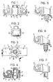
- a one-piece, made of plastic holding element 1 is shown.
- This essentially consists of a storage area 2, which is arranged between two holding areas 3 and 4.
- Each of these holding areas 3 and 4 serves z. B. to hold a pipe, not shown:
- Each holding area 3, 4 consists of two shell-shaped holders with an inner shell 20 or 20 'partially encompassing the circumference of the pipeline and an outer shell 21 or 21' surrounding the inner shell at a distance.
- the two holding areas 3 and 4 are connected to a base body 10 according to FIG. 3 via two connecting areas 27 and 28.
- This storage area 2 is e.g. cylindrical and connected to the base body 10 via three resilient webs 5, 5 ', 5' 'distributed over the circumference.
- the webs 5, 5 ′ and 5 ′′ extend from the open end 12 of this storage area 2 through the intermediate space 8 to the diagonally opposite side of the base body 10. This creates a long way, so that undesirable vibrations avoided and noise reduction is achieved.
- each holding area 3, 4 has a recess 23 or 23 'delimited on the inside by a wall 25 or 25'. These walls merge into the connecting areas 27 and 28 and form part of the base body 10.
- the bearing area 2 has longitudinal ribs 30 distributed on the inside over the circumference of the opening 15. These longitudinal ribs 30 can be incorporated in a profiled bolt (not shown in any more detail), which in turn is fastened, for example, to the body of a motor vehicle.
- the bearing area 2 is designed as an opening 15 with longitudinal ribs 30, FIGS. 5 to 7 show further design options: according to FIG. 5, the bearing area 2 can be made from one foot 31 with two opposing elastic wings 32 and 33, above which an elastic, circumferential sealing lip 30 is arranged.
- the sealing lip 30 can also be omitted.
- a specially designed holding part 37 is used, in which ribs arranged one behind the other are provided; these can be stored in a profiled bolt, not shown, attached to a carrier.
Description
Die Erfindung bezieht sich auf ein einteiliges Halteelement aus Kunststoff, insbesondere für mindestens eine Rohrleitung, mit mindestens einem Lagerbereich und mindestens einem Haltebereich zum teilweisen Umfassen des Rohrleitungsumfanges, wobei der Lagerbereich zwischen zwei Haltebereichen über Federnde Stege angeordnet ist und die beiden Haltebereiche zu einem Grundkörper verbunden sind.The invention relates to a one-piece holding element made of plastic, in particular for at least one pipeline, with at least one storage area and at least one holding area for partially encompassing the circumference of the pipeline, the storage area being arranged between two holding areas via resilient webs and the two holding areas being connected to form a base body are.
Als Stand der Technik ist bereits ein derartiges Halteelement bekannt (DE-PS 30 02 031), welches insbesondere zur Halterung von Benzinleitungen in einem Kraftfahrzeug dient. Hierbei besteht der Haltebereich aus zwei schalenförmigen Halterungen in Form einer, den Rohrleitungsumfang teilweise umfassenden Innenschale und einer die Innenschale mit Abstand umgebenden Außenschale. Der Lagerbereich ist zwischen zwei Haltebereichen angeoranet und weist eine durchgehende Öffnung auf, welche über ein Einschubende auf einem an einem Kraftfahrzeug angeordneten Profilbolzen befestigt ist.Such a holding element is already known as prior art (DE-PS 30 02 031), which is used in particular for holding gasoline lines in a motor vehicle. Here, the holding area consists of two shell-shaped holders in the form of an inner shell, which partially encompasses the circumference of the pipeline, and an outer shell surrounding the inner shell at a distance. The storage area is located between two holding areas and has a continuous opening which is fastened to a profile bolt arranged on a motor vehicle via an insertion end.
Weitere bekannte einteilige Halteelemente (GB-2 098 699 A, GB-PS 1 379 543, DE-OS 28 16 181) sind ähnlich aufgebaut; es besteht jeweils eine unmittelbare Verbindung zwischen dem Lagerbereich und einem einzelnen bzw. mehreren Haltebereichen zur Halterung von rohrförmigen Elementen.Other known one-piece holding elements (GB-2 098 699 A, GB-PS 1 379 543, DE-OS 28 16 181) have a similar structure; there is in each case a direct connection between the storage area and an individual or a plurality of holding areas for holding tubular elements.
Aus diesen bekannten Konstruktionen resultiert der Nachteil, daß Geräuschbildungen und/oder Schwingungen vom Lagerbereich auf die Haltebereiche bzw. umgekehrt übertragen werden können; hierdurch kann sich neben einer Minderung der Lebensdauer auch eine Reduzierung des Fahrkomforts infolge unerwünschter Geräusche ergeben.The disadvantage of these known constructions is that noise and / or vibrations can be transmitted from the storage area to the holding areas or vice versa; In addition to a reduction in the service life, this can also result in a reduction in driving comfort as a result of undesirable noises.
Den gegenüber liegt der vorliegenden Erfindung die Aufgabe zugrunde, ein einteiliges Halteelement der eingangs genannten Art zu schaffen, welches bei einfachem Aufbau die vorgenannten Nachteile vermeidet und Schwingungen reduziert sowie Geräuschsübertragung weitgehend verringert.In contrast, the present invention has for its object to provide a one-piece holding element of the type mentioned, which avoids the aforementioned disadvantages with a simple structure and reduces vibrations and largely reduces noise transmission.
Diese Aufgabe wird erfindungsgemäß durch die Merkmale des Anspruchs 1 gelöst. Hierdurch wird vorteilhafterweise eine weitgehende gezielte Trennung zwischen dem Lagerbereich und dem Haltebereich herbeigeführt, so daß unerwünschte Schwingungen sowie Geräusche nicht zwischen den beiden Teilen des Halteelements übertragen werden können.This object is achieved by the features of claim 1. This advantageously brings about a largely targeted separation between the storage area and the holding area, so that undesired vibrations and noises cannot be transmitted between the two parts of the holding element.
Die Trennung zwischen Lagerbereich und Haltebereichen andererseits zählt bereits zum bekannten Stand der Technik (DE 40 34 545 A1, DE 40 43 546 A1). Diese bekannten Konstruktionen offenbaren jedoch Halteelemente, welche jeweils entweder zweiteilig oder dreiteilig ausgebildet sind, so daß hieraus sowohl Unterschiede in der Herstellung, im Kosten- und Materialaufwand, als auch im Aufbau resultieren.The separation between the storage area and the holding areas on the other hand already belongs to the known prior art (DE 40 34 545 A1, DE 40 43 546 A1). However, these known constructions disclose holding elements, which are each formed either in two parts or three parts, so that this results in differences in production, in cost and material expenditure, and in construction.
Bei einer in der GB-A-2 166 794 offenbarten einteiligen Konstruktion sind die Haltebereiche dagegen über federnde Stege mit einem den Lagerbereich beinhaltenden Körper verbunden, was sich nachteilig auf die Robustheit bzw. Haltbarkeit der Konstruktion gegenüber Dauerbelastungen auswirkt und nicht geräuschmindernd ist. Bei einer anderen aus der DE-U-90 11 879 bekannten Konstruktion bilden die Haltebereiche einen Körper, der über mäanderförmige, lange Stege mit dem davon entfernt liegenden Lagerbereich verbunden ist, um eine weiche Federung zu erreichen. Diese Konstruktion erfordert aber nachteiligerweise eine raumaufwendige, hohe Bauform. Beide Konstruktionen unterscheiden sich so wesentlich von der Erfindung.In the case of a one-piece construction disclosed in GB-A-2 166 794, on the other hand, the holding areas are connected via resilient webs to a body containing the bearing area, which has an adverse effect on the robustness or durability of the construction against continuous loads and is not noise-reducing. In another construction known from DE-U-90 11 879, the holding areas form a body which is connected by meandering, long webs to the bearing area located therefrom in order to achieve a soft suspension. However, this construction disadvantageously requires a space-consuming, high design. Both constructions differ significantly from the invention.
In weiterer Ausbildung der Erfindung kann der Lagerbereich zwischen zwei Haltebereichen angeordnet sein, wobei die beiden Haltebereiche zu einem Grundkörper verbunden sind und der Grundkörper mit den zylinderförmig ausgebildeten Lagerbereich über mehrere federnde Stege verbunden ist. Vorzugsweise können über den Umfang verteilt drei federnde Stege den Grundkörper mit dem Lagerbereich verbinden.In a further embodiment of the invention, the bearing area can be arranged between two holding areas, the two holding areas being connected to form a base body and the base body being connected to the cylindrical bearing area via a plurality of resilient webs. Preferably, three resilient webs distributed over the circumference can connect the base body to the storage area.
Um den Weg zwischen dem Lagerbereich und den Haltebereichen möglichst lang zu erhalten, können sich die Stege diagonal durch einen Zwischenraum zwischen dem Grundkörper und den Lagerbereichen erstrecken. Bei einem einseitig offenen Lagerbereich können sich die Stege in dieser Konfiguration vom offenen Ende des Lagerbereichs durch den Zwischenraum zur diagonal gegenüberliegenden Seite des Grundkörpers erstrecken.In order to keep the path between the storage area and the holding areas as long as possible, the webs can extend diagonally through an intermediate space between the base body and the storage areas. In the case of a storage area which is open on one side, in this configuration the webs can extend from the open end of the storage area through the intermediate space to the diagonally opposite side of the base body.
Bei einer Ausgestaltung des Halteelements, bei welchem jeder Haltebereich aus zwei schalenförmigen Halterungen mit einer den Rohrleitungsumfang teilweise umfassenden Innenschale und einer die Innenschale mit Abstand umgebenden Außenschale besteht, kann jeder Haltebereich innenseitig eine durch eine Wand begrenzte Aussparung aufweisen, wobei beide Wände über Verbindungsbereiche miteinander verbunden sind und einen Zwischenraum umschließen, in dessen Innerem der Lagerbereich angeordnet ist. Dieser Lagerbereich kann innenseitig über den Umfang verteilte Längsrippen aufweisen.In one configuration of the holding element, in which each holding area consists of two shell-shaped holders with an inner shell partially encompassing the circumference of the pipeline and an outer shell surrounding the inner shell at a distance each holding area has a recess delimited by a wall on the inside, the two walls being connected to one another via connecting areas and enclosing an intermediate space in the interior of which the storage area is arranged. This bearing area can have longitudinal ribs distributed on the inside over the circumference.
Weiterhin besteht die Möglichkeit, daß die Stege nicht geradlinig verlaufen, sondern beispielsweise Wellenform aufweisen, so daß hierdurch vorteilhafterweise eine weitere Reduzierung unerwünschter Schwingungen und Geräuschsübertragung bewirkt wird.Furthermore, there is the possibility that the webs do not run in a straight line, but rather, for example, have a wave shape, so that this advantageously brings about a further reduction in undesired vibrations and noise transmission.
Die Erfindung wird nachfolgend anhand eines in der Zeichnung dargestellten Ausführungsbeispiels näher beschrieben.The invention is described below with reference to an embodiment shown in the drawing.
In der Zeichnung zeigen:
- Fig. 1
- eine Seitenansicht eines Halteelements mit einem Lagerbereich und beidseitig davon angeordneten Haltebereichen;
- Fig. 2
- eine Vorderansicht des Halteelements nach Fig. 1;
- Fig. 3
- eine Unteransicht des Halteelements nach Fig. 1;
- Fig. 4
- einen Schnitt gemäß der Linie IV-IV in Fig. 3;
- Fig. 5 bis 7
- verschiedene Ausgestaltungen des Lagerbereichs des Halteelements.
- Fig. 1
- a side view of a holding element with a storage area and holding areas arranged on both sides thereof;
- Fig. 2
- a front view of the holding element of FIG. 1;
- Fig. 3
- a bottom view of the holding element of FIG. 1;
- Fig. 4
- a section along the line IV-IV in Fig. 3;
- 5 to 7
- different configurations of the storage area of the holding element.
In Fig. 1 ist ein einteiliges, aus Kunststoff bestehendes Halteelement 1 dargestellt. Dieses besteht im wesentlichen aus einem Lagerbereich 2, welcher zwischen zwei Haltebereichen 3 und 4 angeordnet ist. Jeder dieser Haltebereiche 3 und 4 dient z. B. zur Halterung einer nicht näher dargestellten Rohrleitung: Hierzu besteht jeder Haltebereich 3, 4 aus zwei schalenförmigen Halterungen mit einer den Rohrleitungsumfang teilweise umfassenden Innenschale 20 bzw. 20' und einer die Innenschale mit Abstand umgebenden Außenschale 21 bzw. 21'. Die beiden Haltebereiche 3 und 4 sind nach Fig. 3 über zwei Verbindungsbereiche 27 und 28 zu einem Grundkörper 10 verbunden.In Fig. 1, a one-piece, made of plastic holding element 1 is shown. This essentially consists of a
Aus Fig. 3 geht weiterhin hervor, daß die Verbindungsbereiche 27 und 28 sowie die Innenseiten der Haltebereiche 3 und 4 einen Zwischenraum 8 umschließen, in dessen Innerem der Lagerbereich 2 angeordnet ist. Dieser Lagerbereich 2 ist z.B. zylinderförmig ausgebildet und über drei über den Umfang verteilte federnde Stege 5, 5', 5'' mit dem Grundkörper 10 verbunden.3 further shows that the
Der Lagerbereich 2 des Halteelements weist nach Fig. 4 eine Öffnung 15 mit einem offenen Ende 12 auf. Wie aus Fig. 4 gleichfalls ersichtlich, erstrecken sich die Stege 5, 5' und 5'' vom offenen Ende 12 dieses Lagerbereichs 2 durch den Zwischenraum 8 zur diagonal gegenüberliegenden Seite des Grundkörpers 10. Damit ist ein langer Weg geschaffen, so daß unerwünschte Schwingungen vermieden und Geräuschdämpfung erzielt wird.4 has an opening 15 with an
Aus Fig. 1 und 4 geht hervor, daß jeder Haltebereich 3, 4 innenseitig eine durch eine Wand 25 bzw. 25' begrenzte Aussparung 23 bzw. 23' aufweist. Diese Wände gehen in die Verbindungsbereiche 27 und 28 über und stellen einen Teil des Grundkörpers 10 dar.1 and 4 show that each holding area 3, 4 has a
Nach Fig. 3 besitzt der Lagerbereich 2 innenseitig über den Umfang der Öffnung 15 verteilte Längsrippen 30. Diese Längsrippen 30 können sich in einen nicht näher dargestellten Profilbolzen einlagern, welcher seinerseits beispielsweise an der Karosserie eines Kraftfahrzeuges befestigt ist.According to FIG. 3, the
Werden nun in die Innenschale 20 bzw. 20' Rohrleitungen eingedrückt, so daß diese in dem erfindungsgemäßen Halteelement lagern, so ist durch die weitgehende Trennung zwischen Lagerbereich reich 2 einerseits und den Haltebereichen 3, 4 andererseits gewährleistet, daß unerwünschte Schwingungen bzw. Geräusche nicht mehr in erheblichem Maße zwischen diesen beiden Bereichen des Halteelements übertragen werden. Lediglich die drei über den Umfang verteilten Stege 5, 5' und 5'' stellen die Verbindung zwischen dem Lagerbereich 2 und dem Haltebereich 3 und 4 her, wobei diese Stege so gestaltet sind, daß möglichst lange Wege vorliegen.If pipes are now pressed into the
Statt der geraden Ausführung der Stege nach Fig. 4 besteht auch die Möglichkeit, diese beispielsweise gewellt auszubilden, so daß eine weitere positive Wegverlängerung erzielt wird.Instead of the straight design of the webs according to FIG. 4, there is also the possibility of making them corrugated, for example, so that a further positive path extension is achieved.
Während bei der Ausführungsform des Halteelements 1 nach Fig. 1 bis Fig. 4 der Lagerbereich 2 als Öffnung 15 mit Längsrippen 30 ausgebildet ist, zeigen die Fig. 5 bis Fig. 7 weitere Gestaltungsmöglichkeiten: Nach Fig. 5 kann der Lagerbereich 2 aus einem Fuß 31 mit zwei einander gegenüberliegenden elastischen Flügeln 32 und 33 bestehen, oberhalb welchen eine elastische, umlaufende Dichtlippe 30 angeordnet ist.While in the embodiment of the holding element 1 according to FIGS. 1 to 4, the
Zwischen der Unterseite dieser Dichtlippe 30 und der oberen jeweiligen Kante der elastischen Flügel 32 und 33 kann sich damit ein Träger mit einer entsprechend gestalteten Öffnung einlagern, wodurch das Halteelement 1 an diesem funktionssicher befestigt ist.Between the underside of this
Die Bauform nach Fig. 6 besteht aus einem Bolzenteil 35 mit einzelnen konischen Elementen und einer elastischen umlaufenden Dichtlippe 30, wodurch eine Einlagerungsmöglichkeit in eine nicht näher dargestellte Öffnung eines Trägers mit Abdichtung gegeben ist.6 consists of a
Bei beiden vorgenannten Ausführungsformen nach Fig. 5 und Fig. 6 kann die Dichtlippe 30 auch entfallen.In both of the aforementioned embodiments according to FIGS. 5 and 6, the sealing
Bei der Bauform nach Fig. 7 findet ein speziell gestaltetes Halteteil 37 Anwendung, bei welchem vorn hintereinander angeordnete Rippen vorgesehen sind; diese können sich in einem nicht näher dargestellten, an einem Träger befestigten Profilbolzen einlagern.7, a specially designed holding
In jedem Fall liegt ein einteiliges Halteelement aus Kunststoff vor, welches eine gezielte weitgehende Trennung zwischen den Haltebereichen 3 und 4 und dem Lagerbereich 2 schafft. Hierbei ist es unwesentlich, wie der Lagerbereich und der Haltebereich ausgestaltet sind; statt der Halbschalen des Haltebereichs kann dieser konstruktiv auch anders ausgebildet sein und andere Elemente anstelle von Rohrleitungen haltern.In any case, there is a one-piece holding element made of plastic, which creates a targeted, extensive separation between the holding areas 3 and 4 and the
Claims (7)
- One-piece holding element (1), made of plastic, in particular for at least one pipe, having at least one supporting region (2) and at least one holding region (3, 4) for partially surrounding the pipe circumference, the supporting region (2) being arranged between two holding regions via resilient webs, and the two holding regions (3, 4) being connected to form a basic body (10), characterized in that the basic body (10) encloses a gap (8) inside which the supporting region (2) is arranged and is connected to the basic body (10) via at least one resilient web (5, 5', 5").
- Holding element according to Claim 1, characterized in that the supporting region (2) is of cylindrical configuration.
- Holding element according to either of Claims 1 or 2, characterized in that three resilient webs (5, 5', 5"), distributed over the circumference, connect the basic body (10) to the supporting region (2).
- Holding element according to one of the preceding claims, characterized in that the webs (5, 5', 5") extend diagonally through the gap (8) between the basic body (10) and the supporting region (2).
- Holding element according to Claim 4, having a supporting region which is open on one side, characterized in that the webs (5, 5', 5") extend from one end (12) of the supporting region (2) through the gap (8) to the diagonally opposite side of the basic body (10).
- Holding element according to one of the preceding claims, each holding region comprising two shell-like holders with an inner shell partially surrounding the pipe circumference and an outer shell surrounding the inner shell with a clearance, characterized in that each holding region (3, 4) has on the inside a cut-out (23, 23') bounded by a wall (25, 25'), and in that the two walls (25, 25') are connected to one another via connecting regions (27, 28) and enclose the gap (8) inside which the supporting region (2) is arranged.
- Holding element according to one of the preceding claims, characterized in that the supporting region (2) has, on the inside, longitudinal ribs distributed over the circumference, consists of a profiled bolt (35) or has elastic wings (32, 33).
Applications Claiming Priority (2)
| Application Number | Priority Date | Filing Date | Title |
|---|---|---|---|
| DE4302408A DE4302408A1 (en) | 1993-01-28 | 1993-01-28 | One-piece holding element |
| DE4302408 | 1993-01-28 |
Publications (2)
| Publication Number | Publication Date |
|---|---|
| EP0612944A1 EP0612944A1 (en) | 1994-08-31 |
| EP0612944B1 true EP0612944B1 (en) | 1996-11-13 |
Family
ID=6479149
Family Applications (1)
| Application Number | Title | Priority Date | Filing Date |
|---|---|---|---|
| EP93120753A Expired - Lifetime EP0612944B1 (en) | 1993-01-28 | 1993-12-22 | One-piece support element |
Country Status (6)
| Country | Link |
|---|---|
| US (1) | US5458303A (en) |
| EP (1) | EP0612944B1 (en) |
| JP (1) | JPH0791570A (en) |
| KR (1) | KR100298551B1 (en) |
| DE (2) | DE4302408A1 (en) |
| ES (1) | ES2095553T3 (en) |
Families Citing this family (29)
| Publication number | Priority date | Publication date | Assignee | Title |
|---|---|---|---|---|
| IT1278968B1 (en) * | 1995-03-03 | 1997-12-02 | Lys Fusion Spa | CLAMP FOR FASTENING CONDUCTOR TUBES AND SIMILAR ORGANS |
| DE19529897A1 (en) * | 1995-08-14 | 1997-02-20 | United Carr Gmbh Trw | Holding element made of plastic |
| DE19540168C2 (en) * | 1995-10-27 | 1997-09-18 | Emhart Inc | Holding element for fastening at least one tubular component to a carrier |
| US5941483A (en) * | 1998-04-24 | 1999-08-24 | Volvo Trucks North America, Inc. | Service line clamp with cable tie mount |
| US6601802B1 (en) * | 1999-12-30 | 2003-08-05 | Lsp Products Group Inc | Method for making extruded acoustic pipe support |
| JP2002349762A (en) | 2001-05-29 | 2002-12-04 | Nippon Pop Rivets & Fasteners Ltd | Holder of pipe |
| US6915990B2 (en) * | 2001-05-29 | 2005-07-12 | Newfrey Llc | Pipe holding fastener |
| JP2002349763A (en) * | 2001-05-30 | 2002-12-04 | Nippon Pop Rivets & Fasteners Ltd | Holder of pipe |
| US6564423B2 (en) | 2001-06-21 | 2003-05-20 | Black & Decker Inc. | Two piece upright handle assembly for a vacuum cleaner system |
| US6604725B1 (en) | 2002-01-24 | 2003-08-12 | Robert Bosch Corporation | Device for securing a hydraulic modulator to a vehicle |
| DE10304033A1 (en) * | 2003-02-01 | 2004-08-05 | Adam Opel Ag | Fastening element for pipes in motor vehicles has insert installed in socket, and cut-out in fastening element extends from outer edge to socket and insert, with width of cut-out smaller than diameter of insert |
| DE10306904C5 (en) * | 2003-02-18 | 2012-05-03 | Itw Automotive Products Gmbh & Co. Kg | retaining element |
| DE10306905C5 (en) * | 2003-02-18 | 2012-05-24 | Itw Automotive Products Gmbh & Co. Kg | retaining element |
| US6926237B2 (en) | 2003-05-29 | 2005-08-09 | Illinois Tool Works Inc. | Vibration damping clip |
| JP2005188578A (en) * | 2003-12-25 | 2005-07-14 | Nippon Pop Rivets & Fasteners Ltd | Clamp for long material such as pipe |
| JP4597535B2 (en) * | 2004-01-22 | 2010-12-15 | 株式会社 日立ディスプレイズ | Liquid crystal display |
| ITTO20040088A1 (en) * | 2004-02-17 | 2004-05-17 | Itw Automotive Italia S R L | CLAMP RETAINING ELEMENT FOR AXIALSIMMETRIC COMPONENTS SUCH AS CABLES OR TUBES, IN PARTICULAR FOR APPLICATION ON VEHICLES |
| US7090169B2 (en) * | 2004-05-20 | 2006-08-15 | Curt Swanson | Retaining clamp for alignment of risers when packing a parachute |
| DE102005032535B4 (en) * | 2005-07-12 | 2008-03-27 | A. Raymond & Cie | Device for fastening at least one object to a carrier part provided with a fastening bolt |
| US7594583B2 (en) * | 2006-02-23 | 2009-09-29 | Gm Global Technology Operations, Inc. | Retaining support member for fuel filler pipe |
| US7770851B2 (en) * | 2006-12-21 | 2010-08-10 | Thomas & Betts International, Inc. | Retaining element including enhanced engagement features |
| US7740209B2 (en) * | 2007-07-27 | 2010-06-22 | Hewlett-Packard Development Company, L.P. | Cable routing device |
| US8162156B1 (en) | 2009-06-29 | 2012-04-24 | Bruce Crisman | Implement holder and methods of use |
| BR112012025177A2 (en) * | 2010-04-02 | 2016-06-21 | Illinois Tool Works | vehicle mount for vibration isolation |
| DE102011114543B4 (en) * | 2011-09-30 | 2013-09-12 | Faurecia Autositze Gmbh | Automotive seat |
| GB201117028D0 (en) * | 2011-10-04 | 2011-11-16 | Rolls Royce Plc | Gas turbine engine mounting arrangements |
| DE102015112207A1 (en) | 2015-07-27 | 2017-02-02 | Newfrey Llc | Clip for fixing an elongated object |
| DE102016222708A1 (en) * | 2016-11-18 | 2018-05-24 | Bayerische Motoren Werke Aktiengesellschaft | Receiving device for receiving a line-shaped component |
| KR102557404B1 (en) * | 2017-05-31 | 2023-07-19 | 삼성전자주식회사 | Washing machine |
Family Cites Families (10)
| Publication number | Priority date | Publication date | Assignee | Title |
|---|---|---|---|---|
| US4591119A (en) * | 1984-03-23 | 1986-05-27 | Trw United-Carr Gmbh | Pipe support |
| DE3440995A1 (en) * | 1984-11-09 | 1986-05-15 | Fa. A. Raymond, 7850 Lörrach | FASTENING ELEMENT FOR PIPELINES |
| JPS6189506U (en) * | 1984-11-19 | 1986-06-11 | ||
| DE3802698C3 (en) * | 1988-01-29 | 1996-09-26 | United Carr Gmbh Trw | Cable holder made of plastic |
| DE3902499A1 (en) * | 1989-01-27 | 1990-08-02 | United Carr Gmbh Trw | PLASTIC HOLDING ELEMENT |
| DE9011879U1 (en) * | 1990-08-16 | 1990-10-18 | A. Raymond Kg, 7850 Loerrach, De | |
| DE4034546C2 (en) * | 1990-10-30 | 1993-09-30 | United Carr Gmbh Trw | Holding element made of plastic |
| DE4039822C1 (en) * | 1990-12-13 | 1992-07-23 | A. Raymond Kg, 7850 Loerrach, De | |
| JP2556979Y2 (en) * | 1991-03-01 | 1997-12-08 | 株式会社ニフコ | Wire and rod clamps |
| US5316245A (en) * | 1991-10-25 | 1994-05-31 | Trw United Carr Gmbh & Co., Kg | Plastic holding element |
-
1993
- 1993-01-28 DE DE4302408A patent/DE4302408A1/en not_active Withdrawn
- 1993-12-22 ES ES93120753T patent/ES2095553T3/en not_active Expired - Lifetime
- 1993-12-22 DE DE59304485T patent/DE59304485D1/en not_active Expired - Fee Related
- 1993-12-22 EP EP93120753A patent/EP0612944B1/en not_active Expired - Lifetime
-
1994
- 1994-01-18 US US08/182,659 patent/US5458303A/en not_active Expired - Lifetime
- 1994-01-26 KR KR1019940001337A patent/KR100298551B1/en not_active IP Right Cessation
- 1994-01-28 JP JP6008185A patent/JPH0791570A/en active Pending
Also Published As
| Publication number | Publication date |
|---|---|
| US5458303A (en) | 1995-10-17 |
| JPH0791570A (en) | 1995-04-04 |
| EP0612944A1 (en) | 1994-08-31 |
| ES2095553T3 (en) | 1997-02-16 |
| KR940018573A (en) | 1994-08-18 |
| DE59304485D1 (en) | 1996-12-19 |
| DE4302408A1 (en) | 1994-08-04 |
| KR100298551B1 (en) | 2001-11-22 |
Similar Documents
| Publication | Publication Date | Title |
|---|---|---|
| EP0612944B1 (en) | One-piece support element | |
| EP0758728B1 (en) | Plastic supporting element | |
| EP0726401B1 (en) | Connection between a support and a panel | |
| EP0379722B1 (en) | Retaining element consisting of plastics | |
| EP0761986B1 (en) | Plastic connecting element | |
| DE3713503C1 (en) | Plastic cover | |
| EP0421056B1 (en) | Plastic fastening element | |
| EP0483636B1 (en) | Plastics retaining element | |
| EP0621169A1 (en) | Plastic closure cap | |
| DE2952176A1 (en) | GUIDE HANDLEBARS FOR MOTOR VEHICLE SUSPENSIONS | |
| DE2937083C2 (en) | Wheel covers, in particular for the wheels of passenger cars | |
| DE3610829A1 (en) | ELASTIC BEARING PART AS INSERT IN A HOLDING ELEMENT TO HOLD AT LEAST ONE CABLE | |
| EP0155485B1 (en) | Axial ball pivot for link rods in motor vehicles | |
| DE3048793C2 (en) | Carrying bodies for wheel guide members of motor vehicle wheels, in particular rear wheels | |
| DE2943139A1 (en) | WHEEL COVER, ESPECIALLY FOR WHEELS OF PASSENGER CARS | |
| DE3739514A1 (en) | POETRY | |
| DE2331324C3 (en) | Windshield wipers for vehicles, in particular motor vehicles | |
| DE3011345C2 (en) | Connection of pipes with edge areas of metal sheets or the like. flat components | |
| DE7415154U (en) | BEARING BOX WITH BEARING AXLE IN PARTICULAR TO ACCOMMODATE A SUN VISOR IN VEHICLES | |
| EP3568604B1 (en) | Bellows comprising at least one internal groove | |
| DE19652874C1 (en) | Plastic fastening dowel for motor vehicle | |
| DE102017223636A1 (en) | Assembly unit and fixing sleeve for such a mounting unit | |
| EP0672836A1 (en) | Fixing device | |
| DE2810163A1 (en) | REEL CARRIER WITH SUPPORT ELEMENTS PARALLEL TO ITS AXIS | |
| DE10216349C1 (en) | Housing for an airbag device with stiffeners |
Legal Events
| Date | Code | Title | Description |
|---|---|---|---|
| PUAI | Public reference made under article 153(3) epc to a published international application that has entered the european phase |
Free format text: ORIGINAL CODE: 0009012 |
|
| AK | Designated contracting states |
Kind code of ref document: A1 Designated state(s): DE ES FR GB NL SE |
|
| 17P | Request for examination filed |
Effective date: 19940802 |
|
| 17Q | First examination report despatched |
Effective date: 19941114 |
|
| GRAG | Despatch of communication of intention to grant |
Free format text: ORIGINAL CODE: EPIDOS AGRA |
|
| GRAH | Despatch of communication of intention to grant a patent |
Free format text: ORIGINAL CODE: EPIDOS IGRA |
|
| GRAH | Despatch of communication of intention to grant a patent |
Free format text: ORIGINAL CODE: EPIDOS IGRA |
|
| GRAA | (expected) grant |
Free format text: ORIGINAL CODE: 0009210 |
|
| AK | Designated contracting states |
Kind code of ref document: B1 Designated state(s): DE ES FR GB NL SE |
|
| PG25 | Lapsed in a contracting state [announced via postgrant information from national office to epo] |
Ref country code: NL Free format text: LAPSE BECAUSE OF FAILURE TO SUBMIT A TRANSLATION OF THE DESCRIPTION OR TO PAY THE FEE WITHIN THE PRESCRIBED TIME-LIMIT Effective date: 19961113 |
|
| REF | Corresponds to: |
Ref document number: 59304485 Country of ref document: DE Date of ref document: 19961219 |
|
| PG25 | Lapsed in a contracting state [announced via postgrant information from national office to epo] |
Ref country code: SE Effective date: 19970213 |
|
| ET | Fr: translation filed | ||
| REG | Reference to a national code |
Ref country code: ES Ref legal event code: FG2A Ref document number: 2095553 Country of ref document: ES Kind code of ref document: T3 |
|
| GBT | Gb: translation of ep patent filed (gb section 77(6)(a)/1977) |
Effective date: 19970123 |
|
| NLV1 | Nl: lapsed or annulled due to failure to fulfill the requirements of art. 29p and 29m of the patents act | ||
| PLBE | No opposition filed within time limit |
Free format text: ORIGINAL CODE: 0009261 |
|
| STAA | Information on the status of an ep patent application or granted ep patent |
Free format text: STATUS: NO OPPOSITION FILED WITHIN TIME LIMIT |
|
| 26N | No opposition filed | ||
| REG | Reference to a national code |
Ref country code: GB Ref legal event code: IF02 |
|
| PGFP | Annual fee paid to national office [announced via postgrant information from national office to epo] |
Ref country code: ES Payment date: 20071217 Year of fee payment: 15 |
|
| PGFP | Annual fee paid to national office [announced via postgrant information from national office to epo] |
Ref country code: GB Payment date: 20071106 Year of fee payment: 15 |
|
| PGFP | Annual fee paid to national office [announced via postgrant information from national office to epo] |
Ref country code: DE Payment date: 20071228 Year of fee payment: 15 |
|
| PGFP | Annual fee paid to national office [announced via postgrant information from national office to epo] |
Ref country code: FR Payment date: 20071204 Year of fee payment: 15 |
|
| GBPC | Gb: european patent ceased through non-payment of renewal fee |
Effective date: 20081222 |
|
| REG | Reference to a national code |
Ref country code: FR Ref legal event code: ST Effective date: 20090831 |
|
| PG25 | Lapsed in a contracting state [announced via postgrant information from national office to epo] |
Ref country code: DE Free format text: LAPSE BECAUSE OF NON-PAYMENT OF DUE FEES Effective date: 20090701 |
|
| PG25 | Lapsed in a contracting state [announced via postgrant information from national office to epo] |
Ref country code: GB Free format text: LAPSE BECAUSE OF NON-PAYMENT OF DUE FEES Effective date: 20081222 |
|
| REG | Reference to a national code |
Ref country code: ES Ref legal event code: FD2A Effective date: 20081223 |
|
| PG25 | Lapsed in a contracting state [announced via postgrant information from national office to epo] |
Ref country code: FR Free format text: LAPSE BECAUSE OF NON-PAYMENT OF DUE FEES Effective date: 20081231 Ref country code: ES Free format text: LAPSE BECAUSE OF NON-PAYMENT OF DUE FEES Effective date: 20081223 |