EP0612941A1 - Disc valve for gas flow control - Google Patents
Disc valve for gas flow control Download PDFInfo
- Publication number
- EP0612941A1 EP0612941A1 EP94830084A EP94830084A EP0612941A1 EP 0612941 A1 EP0612941 A1 EP 0612941A1 EP 94830084 A EP94830084 A EP 94830084A EP 94830084 A EP94830084 A EP 94830084A EP 0612941 A1 EP0612941 A1 EP 0612941A1
- Authority
- EP
- European Patent Office
- Prior art keywords
- ring
- valve
- axis
- valve element
- pipeline
- Prior art date
- Legal status (The legal status is an assumption and is not a legal conclusion. Google has not performed a legal analysis and makes no representation as to the accuracy of the status listed.)
- Granted
Links
- 239000007787 solid Substances 0.000 claims abstract description 8
- 238000009434 installation Methods 0.000 claims description 2
- 230000001747 exhibiting effect Effects 0.000 claims 1
- 239000012530 fluid Substances 0.000 abstract description 3
- 239000007789 gas Substances 0.000 description 21
- 230000000694 effects Effects 0.000 description 3
- 239000000203 mixture Substances 0.000 description 3
- 230000001105 regulatory effect Effects 0.000 description 3
- 239000000446 fuel Substances 0.000 description 2
- VNWKTOKETHGBQD-UHFFFAOYSA-N methane Chemical compound C VNWKTOKETHGBQD-UHFFFAOYSA-N 0.000 description 2
- 238000007664 blowing Methods 0.000 description 1
- 239000011449 brick Substances 0.000 description 1
- 238000002485 combustion reaction Methods 0.000 description 1
- 238000010276 construction Methods 0.000 description 1
- 238000006073 displacement reaction Methods 0.000 description 1
- 238000010304 firing Methods 0.000 description 1
- 239000011521 glass Substances 0.000 description 1
- 238000010438 heat treatment Methods 0.000 description 1
- 238000004519 manufacturing process Methods 0.000 description 1
- 238000012544 monitoring process Methods 0.000 description 1
- 239000003345 natural gas Substances 0.000 description 1
- 239000003973 paint Substances 0.000 description 1
- 230000000717 retained effect Effects 0.000 description 1
- 238000007789 sealing Methods 0.000 description 1
- 238000009827 uniform distribution Methods 0.000 description 1
Images


Classifications
-
- F—MECHANICAL ENGINEERING; LIGHTING; HEATING; WEAPONS; BLASTING
- F16—ENGINEERING ELEMENTS AND UNITS; GENERAL MEASURES FOR PRODUCING AND MAINTAINING EFFECTIVE FUNCTIONING OF MACHINES OR INSTALLATIONS; THERMAL INSULATION IN GENERAL
- F16K—VALVES; TAPS; COCKS; ACTUATING-FLOATS; DEVICES FOR VENTING OR AERATING
- F16K3/00—Gate valves or sliding valves, i.e. cut-off apparatus with closing members having a sliding movement along the seat for opening and closing
- F16K3/02—Gate valves or sliding valves, i.e. cut-off apparatus with closing members having a sliding movement along the seat for opening and closing with flat sealing faces; Packings therefor
- F16K3/04—Gate valves or sliding valves, i.e. cut-off apparatus with closing members having a sliding movement along the seat for opening and closing with flat sealing faces; Packings therefor with pivoted closure members
Definitions
- the present invention relates to a gas flow control valve, in particular for industrial burners.
- industrial burner generically describes those appliances used to generate heat in a variety of industrial applications, for example the firing of paints or bricks in infrared tunnel kilns, or in special equipment for the manufacture of components fashioned in glass (vials, bottles, electric light bulbs, etc.).
- Certain of these burners utilize a mixture of air (serving to assist combustion, which is delivered forcibly either by suction or by blowing, according to the type of engineering solution adopted in the burner) and natural gas (the fuel), supplied by respective nozzles with interconnected regulating levers.
- air serving to assist combustion
- natural gas the fuel
- burners encountered in domestic applications are used typically to heat a fluid of which the temperature does not need to be held at a constant value, so that the gas can be supplied to the appliance by means of a simple on/off control
- burners of the industrial type in question are designed for a type of space heating in which constant temperatures are fundamentally important, and achieved by monitoring and direct regulation of the fuel mixture, or at least the gas, supplied to the kiln.
- variable flow on/off valves installed on the gas inlet pipeline.
- the valve most widely adopted is a rotary "disc” type driven by a stepping motor or similar actuator, designed for installation on a straight gas inlet pipeline, which comprises at least one annular sealing element interposed between two sections of the pipeline and occupying a position outside their circumference, with which the regulating disc is paired in flush contact; the disc is keyed at the centre in such a way as to rotate about its own axis (vertically disposed in most instances) when activated from externally of the valve, thereby widening or narrowing the passage afforded by the annular element and thus varying the flow of gas to the burner during operation.
- the architecture of the disc valve thus outlined, as exhibited hitherto (the present specification is not concerned with the many control valves having pneumatically or hydraulically controlled elements and driven vertically with axis disposed normal to the axis of the pipeline, since these belong to a decidedly superior class of application), does not allow for a proportional type of control, inasmuch as the dimensional values of the flow passages are such that a steady angular variation of the control means will not always give place to a proportional (or rather controllable) change in the rate of flow at which fluid is admitted; moreover, the margin for error increases as different setting ranges are selected for the valve.
- the object of the present invention is to overcome such drawbacks by providing a gas flow control valve featuring simplicity in construction, and economy, and affording a flow passage of which the regulation will be both finer than obtainable hitherto and effectively proportional to the input applied by the external control, thereby responding more exactly to given operating requirements.
- valve according to the present invention is designed for application to a gas pipeline incorporating a first half-casing 1 and a second half-casing 2 each with a centre hole, which are matched, mutually opposed and connected one to the other axially by way of respective flanges 1f and 2f.
- the half-casings 1 and 2 are connected respectively to a first pipeline 3, through which gas flows at a given inlet pressure, and to a second pipeline 4 through which the gas flows at an outlet pressure determined by the pressure drop registering across the valve;
- the valve itself is positioned between the two matched half-casings 1 and 2 and comprises a seat 5 supporting a first valve element of disc type, denoted 7 in its entirety, rotatable through a given angle ⁇ (preferably a right angle, as in the particular example illustrated) about its own vertical axis through the agency of external drive means 8 and creating a flow passage L by which the gas is allowed to pass at a given rate of flow from the first pipeline 3 to the second pipeline 4.
- ⁇ preferably a right angle, as in the particular example illustrated
- the half-casings 1 and 2 also combine to create a first radial chamber 9 (fig 1) affording passage to the gas and housing the valve element 7, disposed with its axis of rotation normal to the axis X of the connected pipelines 3 and 4;
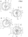
- the valve element 7 comprises a first ring 6, which functions as a support as well as partially occluding the first radial chamber 9 against the flow of gas in that it affords a solid sector measuring approximately 90° (fig 4a), also a second ring 10 (fig b) disposed parallel to the first ring 6, connected rigidly to the drive means 8 and rotatable thus about its own vertical axis Y through a plurality of angularly distinct intermediate positions between two limit positions, separated by the angle ⁇ aforementioned, in which the flow passage L is completely occluded and open, respectively.
- a first radial chamber 9 (fig 1) affording passage to the gas and housing the valve element 7, disposed with its axis of rotation normal to the axis X of the
- first ring 6 occupies a fixed position within the assembled valve, retained by a reference pin denoted 6p in figs 1 and 4a, whilst the second ring 10 is rigidly associated with a spindle 13, keyed to a sleeve of square profile 10q (discernible also in fig 4b) made secure by means of a further pin 13p, and coupled thus to the drive means 8 (see fig 1).
- the valve comprises a third ring 11, interposed between the first and second rings 6 and 10 and serving in effect to create a second valve element of radial depth denoted S, also proportioned to the preferred angle ⁇ (fig 4c), which is rotatable independently of the second ring 10 through the agency of second drive means, denoted 8s, between a limit position of non-interference in the radial direction, and a limit position of radial interference in which the second valve element is displaced, likewise through the same angle ⁇ and within the compass of the flow passage L defined by the first valve element 7, in such a way as to determine a different rate of flow between the pipelines 3 and 4.
- the operating section of the valve disclosed is duplicated by incorporating a second radial chamber 12 into the half-casings 1 and 2, matched symmetrically to the first radial chamber 9 and fitted with a corresponding set of first, second and third rings denoted 6', 10' and 11' respectively, identical to those of the first radial chamber 9; the duplicate second ring 10' is coupled to the drive means 8 in the manner already described, i.e. by way of the spindle 13, which extends vertically through the half-casings 1 and 2 to interconnect the two sets of rings.
- the drive means denoted 8 might consist, by way of example, in an electric actuator 14 (conventional in embodiment and therefore indicated only in part) secured to the top of the assembled half-casings 1 and 2 by way of a mounting bracket 15 and coupled thus to the spindle 13, which occupies a central position within the half-casings 1 and 2, rotatable about its own vertical axis and carrying the keyed second rings 10 and 10'.
- an electric actuator 14 (conventional in embodiment and therefore indicated only in part) secured to the top of the assembled half-casings 1 and 2 by way of a mounting bracket 15 and coupled thus to the spindle 13, which occupies a central position within the half-casings 1 and 2, rotatable about its own vertical axis and carrying the keyed second rings 10 and 10'.
- Figs 2 and 3 afford a more detailed illustration of the second drive means 8s, which are composed of a housing 16 associated laterally with one of the two half-casings 1 or 2, disposed at right angles to the axis of the pipelines 3 and 4, also a vertical pivot 17 positioned internally of the housing 16, able to rotate about its own axis, and two serrated wheels 18 and 19 keyed one to each end of the pivot and in mesh with corresponding serrations afforded by the two respective third rings 11 and 11'; the vertical pivot 17 presents a shank 21 of reduced diameter 21 that projects from the housing 16 and is connected to a manual adjustment lever 22 by means of which to select the position of the third rings 11 and 11'.
- the angular positions assumed by the second rings 10 and 10' can be many in number (as discernible from fig 4d), according to the required flow rate.
- the range of adjustment within which the flow F of gas is regulated can be changed (for example, where a valve may be required to service differing flow demands) by means of the third ring 11 (11'), which impinges radially on the flow passage L afforded by the adjacent second ring 10 (10'). More precisely, the effect of repositioning the third ring 11 (11') by operating the lever 22 (arrow F2, fig 4), which induces rotation between its two limit positions, is that the flow of gas allowed through the radial chamber 9 (12) can be proportioned to the area of the passage afforded by the second ring 10 (10'), minus the solid portion of the third ring 11 (11') occupying the passage (i.e. L - S, as discernible from fig 4).
- valve according to the present invention is remarkably versatile in operation and readily adaptable to different requirements in application; in effect, the valve can be assembled with one only or with two sets of rings 6, 10 and 11, and moreover, the third ring 11 is easily rotated back and forth to the end of altering the adjustment range, without stripping down the valve and replacing the rings.
- the rate of flow is therefore changed by metering in two different directions (angular and radial, in relation to the flow passage), thereby affording a simpler type of control, with clear benefits over comparable prior art solutions in terms of improved consumption, efficiency and reliability.
- the rings of the valve element 7 thus far described and illustrated exhibit a regular geometry which determines a proportional relationship between the angular displacement of the spindle 13 and the area of the flow passage L; this geometry might also be modified and adapted, according to requirements, in that the shape of the solid portions exhibited by the rings 6, 10 and 11 could be different from that illustrated in bold lines, for example stepped or non-linear (phantom lines 10t and llt in figs 4b and 4c), in such a way as to occasion variations of the flow passage that are not exactly proportional (as with the modified profile denoted Pr in fig 4).
- This added measure of control achievable simply by changing the rings of the valve element, confirms the validity of the solution disclosed.
- Fig 5 illustrates a simplified embodiment of the valve which comprises only the first and second rings 6 and 10; in this instance ordinary distance rings D1 and D2 are added to restore the original dimensional values, with respect to the remaining components of the valve.
Landscapes
- Engineering & Computer Science (AREA)
- General Engineering & Computer Science (AREA)
- Mechanical Engineering (AREA)
- Taps Or Cocks (AREA)
- Safety Valves (AREA)
- Lift Valve (AREA)
- Multiple-Way Valves (AREA)
- Mechanically-Actuated Valves (AREA)
- Sampling And Sample Adjustment (AREA)
- Feeding And Controlling Fuel (AREA)
- Sliding Valves (AREA)
Abstract
Description
- The present invention relates to a gas flow control valve, in particular for industrial burners.
- The term industrial burner generically describes those appliances used to generate heat in a variety of industrial applications, for example the firing of paints or bricks in infrared tunnel kilns, or in special equipment for the manufacture of components fashioned in glass (vials, bottles, electric light bulbs, etc.).
- Certain of these burners utilize a mixture of air (serving to assist combustion, which is delivered forcibly either by suction or by blowing, according to the type of engineering solution adopted in the burner) and natural gas (the fuel), supplied by respective nozzles with interconnected regulating levers. Most gas burners encountered in domestic applications are used typically to heat a fluid of which the temperature does not need to be held at a constant value, so that the gas can be supplied to the appliance by means of a simple on/off control, whereas burners of the industrial type in question are designed for a type of space heating in which constant temperatures are fundamentally important, and achieved by monitoring and direct regulation of the fuel mixture, or at least the gas, supplied to the kiln.
- To this end, use is made of variable flow on/off valves installed on the gas inlet pipeline. The valve most widely adopted is a rotary "disc" type driven by a stepping motor or similar actuator, designed for installation on a straight gas inlet pipeline, which comprises at least one annular sealing element interposed between two sections of the pipeline and occupying a position outside their circumference, with which the regulating disc is paired in flush contact; the disc is keyed at the centre in such a way as to rotate about its own axis (vertically disposed in most instances) when activated from externally of the valve, thereby widening or narrowing the passage afforded by the annular element and thus varying the flow of gas to the burner during operation.
- The architecture of the disc valve thus outlined, as exhibited hitherto (the present specification is not concerned with the many control valves having pneumatically or hydraulically controlled elements and driven vertically with axis disposed normal to the axis of the pipeline, since these belong to a decidedly superior class of application), does not allow for a proportional type of control, inasmuch as the dimensional values of the flow passages are such that a steady angular variation of the control means will not always give place to a proportional (or rather controllable) change in the rate of flow at which fluid is admitted; moreover, the margin for error increases as different setting ranges are selected for the valve.
- In short, significant problems are experienced in adapting a given valve assembly to the different demands of a burner, even when utilizing electronic control equipment with a simple rotary control and linear output.
- Accordingly, the object of the present invention is to overcome such drawbacks by providing a gas flow control valve featuring simplicity in construction, and economy, and affording a flow passage of which the regulation will be both finer than obtainable hitherto and effectively proportional to the input applied by the external control, thereby responding more exactly to given operating requirements.
- The stated object is realized in a control valve as characterized in the appended claims.
- The invention will now be described in detail, by way of example, with the aid of the accompanying drawings, in which:
- fig 1 shows a gas flow control valve according to the invention, viewed in vertical section;
- fig 2 shows a detail of the valve of fig 1, viewed in vertical section;
- fig 3 shows the detail of fig 2, viewed in plan from above;
- figs 4a, 4b, 4c and 4d are schematic plan views of the valve elements in a valve as in fig 1, showing possible compositions and combinations of the rings which determine the dimensions of the flow passage afforded to the gas;
- fig 5 shows a detail of the valve of fig 1 in an alternative embodiment.
- Referring to the accompanying drawings, the valve according to the present invention is designed for application to a gas pipeline incorporating a first half-
casing 1 and a second half-casing 2 each with a centre hole, which are matched, mutually opposed and connected one to the other axially by way ofrespective flanges - The half-
casings first pipeline 3, through which gas flows at a given inlet pressure, and to asecond pipeline 4 through which the gas flows at an outlet pressure determined by the pressure drop registering across the valve; the valve itself is positioned between the two matched half-casings seat 5 supporting a first valve element of disc type, denoted 7 in its entirety, rotatable through a given angle α (preferably a right angle, as in the particular example illustrated) about its own vertical axis through the agency of external drive means 8 and creating a flow passage L by which the gas is allowed to pass at a given rate of flow from thefirst pipeline 3 to thesecond pipeline 4. - The half-
casings valve element 7, disposed with its axis of rotation normal to the axis X of the connectedpipelines valve element 7 comprises afirst ring 6, which functions as a support as well as partially occluding the firstradial chamber 9 against the flow of gas in that it affords a solid sector measuring approximately 90° (fig 4a), also a second ring 10 (fig b) disposed parallel to thefirst ring 6, connected rigidly to the drive means 8 and rotatable thus about its own vertical axis Y through a plurality of angularly distinct intermediate positions between two limit positions, separated by the angle α aforementioned, in which the flow passage L is completely occluded and open, respectively. - More exactly, the
first ring 6 occupies a fixed position within the assembled valve, retained by a reference pin denoted 6p in figs 1 and 4a, whilst thesecond ring 10 is rigidly associated with aspindle 13, keyed to a sleeve of square profile 10q (discernible also in fig 4b) made secure by means of afurther pin 13p, and coupled thus to the drive means 8 (see fig 1). - In the preferred embodiment of fig 1, the valve comprises a
third ring 11, interposed between the first andsecond rings second ring 10 through the agency of second drive means, denoted 8s, between a limit position of non-interference in the radial direction, and a limit position of radial interference in which the second valve element is displaced, likewise through the same angle α and within the compass of the flow passage L defined by thefirst valve element 7, in such a way as to determine a different rate of flow between thepipelines - As discernible in fig 1, the operating section of the valve disclosed is duplicated by incorporating a second
radial chamber 12 into the half-casings radial chamber 9 and fitted with a corresponding set of first, second and third rings denoted 6', 10' and 11' respectively, identical to those of the firstradial chamber 9; the duplicate second ring 10' is coupled to the drive means 8 in the manner already described, i.e. by way of thespindle 13, which extends vertically through the half-casings - The drive means denoted 8 might consist, by way of example, in an electric actuator 14 (conventional in embodiment and therefore indicated only in part) secured to the top of the assembled half-
casings mounting bracket 15 and coupled thus to thespindle 13, which occupies a central position within the half-casings second rings 10 and 10'. - Figs 2 and 3 afford a more detailed illustration of the second drive means 8s, which are composed of a
housing 16 associated laterally with one of the two half-casings pipelines vertical pivot 17 positioned internally of thehousing 16, able to rotate about its own axis, and twoserrated wheels third rings vertical pivot 17 presents ashank 21 of reduceddiameter 21 that projects from thehousing 16 and is connected to amanual adjustment lever 22 by means of which to select the position of thethird rings - The operation of a valve thus embodied will now be described.
- Gas flowing in the direction indicated by the arrow denoted F in fig 1 passes from the
inlet pipeline 3 into the relative half-casing 1, through the flow passage L afforded by thesecond rings 10 and 10' and into the tworadial chambers casing 2 and away from the valve by way of theoutlet pipeline 4. - To vary the rate at which gas flows through the valve, it suffices to enlarge or restrict the flow passage L created by each
second ring 10 and 10' in combination with the open portion of the relativefirst ring 6 and 6'; this is effected by rotating the spindle 13 (arrow F1 in figs 1 and 4) in such a way that thesecond rings 10 and 10' are displaced in relation to thefirst rings 6 and 6', assuming a different angular position with each movement and widening or narrowing the opening in consequence. - Evidently, the angular positions assumed by the
second rings 10 and 10' can be many in number (as discernible from fig 4d), according to the required flow rate. - The range of adjustment within which the flow F of gas is regulated can be changed (for example, where a valve may be required to service differing flow demands) by means of the third ring 11 (11'), which impinges radially on the flow passage L afforded by the adjacent second ring 10 (10'). More precisely, the effect of repositioning the third ring 11 (11') by operating the lever 22 (arrow F2, fig 4), which induces rotation between its two limit positions, is that the flow of gas allowed through the radial chamber 9 (12) can be proportioned to the area of the passage afforded by the second ring 10 (10'), minus the solid portion of the third ring 11 (11') occupying the passage (i.e. L - S, as discernible from fig 4).
- It will be clear from the foregoing that the valve according to the present invention is remarkably versatile in operation and readily adaptable to different requirements in application; in effect, the valve can be assembled with one only or with two sets of
rings third ring 11 is easily rotated back and forth to the end of altering the adjustment range, without stripping down the valve and replacing the rings. - The rate of flow is therefore changed by metering in two different directions (angular and radial, in relation to the flow passage), thereby affording a simpler type of control, with clear benefits over comparable prior art solutions in terms of improved consumption, efficiency and reliability.
- The rings of the
valve element 7 thus far described and illustrated exhibit a regular geometry which determines a proportional relationship between the angular displacement of thespindle 13 and the area of the flow passage L; this geometry might also be modified and adapted, according to requirements, in that the shape of the solid portions exhibited by therings phantom lines 10t and llt in figs 4b and 4c), in such a way as to occasion variations of the flow passage that are not exactly proportional (as with the modified profile denoted Pr in fig 4). This added measure of control, achievable simply by changing the rings of the valve element, confirms the validity of the solution disclosed. - Fig 5 illustrates a simplified embodiment of the valve which comprises only the first and
second rings - The further option exists of positioning the rings of fig 4 differently, that is, not with the solid portions disposed asymmetrically in relation to the flow of gas, denoted FG, but rather symmetrically in such a manner as to limit or at all events to ensure a uniform distribution of pressure losses attributable to friction.
Claims (7)
characterized
Applications Claiming Priority (2)
| Application Number | Priority Date | Filing Date | Title |
|---|---|---|---|
| ITBO930069 | 1993-02-26 | ||
| IT93BO000069A IT1266275B1 (en) | 1993-02-26 | 1993-02-26 | GAS FLOW REGULATION VALVE. |
Publications (2)
| Publication Number | Publication Date |
|---|---|
| EP0612941A1 true EP0612941A1 (en) | 1994-08-31 |
| EP0612941B1 EP0612941B1 (en) | 1998-07-08 |
Family
ID=11338746
Family Applications (1)
| Application Number | Title | Priority Date | Filing Date |
|---|---|---|---|
| EP94830084A Expired - Lifetime EP0612941B1 (en) | 1993-02-26 | 1994-02-24 | Gas flow control valve arrangement |
Country Status (5)
| Country | Link |
|---|---|
| EP (1) | EP0612941B1 (en) |
| AT (1) | ATE168176T1 (en) |
| DE (1) | DE69411416T2 (en) |
| ES (1) | ES2119134T3 (en) |
| IT (1) | IT1266275B1 (en) |
Cited By (1)
| Publication number | Priority date | Publication date | Assignee | Title |
|---|---|---|---|---|
| EP1744086A1 (en) | 2005-07-15 | 2007-01-17 | Immergas S.p.A. | A device for regulating the flow rate of a liquid circulating in a boiler |
Citations (3)
| Publication number | Priority date | Publication date | Assignee | Title |
|---|---|---|---|---|
| DE70617C (en) * | G. gröndal in Pitkäranta, Finnland | Rotary shut-off valve with flat mirror and crossbars in the valve and seat body | ||
| FR992678A (en) * | 1944-08-01 | 1951-10-22 | Stop valve, especially for sprayer lance | |
| EP0097315A2 (en) * | 1982-06-21 | 1984-01-04 | Progress-Werk Oberkirch Ag | Oil burner arrangement for field ranges |
-
1993
- 1993-02-26 IT IT93BO000069A patent/IT1266275B1/en active IP Right Grant
-
1994
- 1994-02-24 DE DE69411416T patent/DE69411416T2/en not_active Expired - Lifetime
- 1994-02-24 ES ES94830084T patent/ES2119134T3/en not_active Expired - Lifetime
- 1994-02-24 EP EP94830084A patent/EP0612941B1/en not_active Expired - Lifetime
- 1994-02-24 AT AT94830084T patent/ATE168176T1/en active
Patent Citations (3)
| Publication number | Priority date | Publication date | Assignee | Title |
|---|---|---|---|---|
| DE70617C (en) * | G. gröndal in Pitkäranta, Finnland | Rotary shut-off valve with flat mirror and crossbars in the valve and seat body | ||
| FR992678A (en) * | 1944-08-01 | 1951-10-22 | Stop valve, especially for sprayer lance | |
| EP0097315A2 (en) * | 1982-06-21 | 1984-01-04 | Progress-Werk Oberkirch Ag | Oil burner arrangement for field ranges |
Cited By (1)
| Publication number | Priority date | Publication date | Assignee | Title |
|---|---|---|---|---|
| EP1744086A1 (en) | 2005-07-15 | 2007-01-17 | Immergas S.p.A. | A device for regulating the flow rate of a liquid circulating in a boiler |
Also Published As
| Publication number | Publication date |
|---|---|
| DE69411416T2 (en) | 1998-11-05 |
| IT1266275B1 (en) | 1996-12-27 |
| ITBO930069A1 (en) | 1994-08-27 |
| ATE168176T1 (en) | 1998-07-15 |
| ITBO930069A0 (en) | 1993-02-26 |
| DE69411416D1 (en) | 1998-08-13 |
| ES2119134T3 (en) | 1998-10-01 |
| EP0612941B1 (en) | 1998-07-08 |
Similar Documents
| Publication | Publication Date | Title |
|---|---|---|
| AU2008355012B2 (en) | Valve combination for regulating the flow rate or differential pressure | |
| US5238398A (en) | Variable orifice gas modulating valve | |
| EP1629335B1 (en) | Convertible control device capable of regulating fluid pressure for multiple fluid types and associated method of use | |
| US3882897A (en) | Mixing valve | |
| US7337804B2 (en) | Mixing valves | |
| US4793798A (en) | Burner apparatus | |
| US4972877A (en) | Bypass valve | |
| KR20090125034A (en) | Heating system | |
| EP1024332A2 (en) | Servocontrolled valve for air-conditioning systems known as four pipes systems | |
| CA1306402C (en) | Three-way valve | |
| US3371699A (en) | Gas burner with proportional mixer | |
| EP0612941B1 (en) | Gas flow control valve arrangement | |
| US4653524A (en) | Control valve assembly | |
| US3146794A (en) | Gas valves | |
| US3200842A (en) | Stop valve and inclined port valve with common operator | |
| CN114526353B (en) | Gas distribution chamber assembly of gas valve and gas valve | |
| CN105509058A (en) | high modulation range mixer and premix system comprising thereof | |
| TWM619812U (en) | Wide heating value gas stove | |
| RU1814001C (en) | Cutting-off and controlling arrangement for heating system | |
| CN114526354B (en) | Gas valve | |
| US3138037A (en) | Differential rotation mechanism | |
| US3469780A (en) | Automatic temperature control | |
| KR0165589B1 (en) | Hot water temperature control valve | |
| US3341120A (en) | Control device and parts therefor or the like | |
| JPH025241Y2 (en) |
Legal Events
| Date | Code | Title | Description |
|---|---|---|---|
| PUAI | Public reference made under article 153(3) epc to a published international application that has entered the european phase |
Free format text: ORIGINAL CODE: 0009012 |
|
| AK | Designated contracting states |
Kind code of ref document: A1 Designated state(s): AT BE CH DE ES FR GB IT LI LU NL |
|
| 17P | Request for examination filed |
Effective date: 19941025 |
|
| 17Q | First examination report despatched |
Effective date: 19960523 |
|
| GRAG | Despatch of communication of intention to grant |
Free format text: ORIGINAL CODE: EPIDOS AGRA |
|
| GRAG | Despatch of communication of intention to grant |
Free format text: ORIGINAL CODE: EPIDOS AGRA |
|
| GRAH | Despatch of communication of intention to grant a patent |
Free format text: ORIGINAL CODE: EPIDOS IGRA |
|
| GRAH | Despatch of communication of intention to grant a patent |
Free format text: ORIGINAL CODE: EPIDOS IGRA |
|
| GRAA | (expected) grant |
Free format text: ORIGINAL CODE: 0009210 |
|
| AK | Designated contracting states |
Kind code of ref document: B1 Designated state(s): AT BE CH DE ES FR GB IT LI LU NL |
|
| PG25 | Lapsed in a contracting state [announced via postgrant information from national office to epo] |
Ref country code: NL Free format text: LAPSE BECAUSE OF FAILURE TO SUBMIT A TRANSLATION OF THE DESCRIPTION OR TO PAY THE FEE WITHIN THE PRESCRIBED TIME-LIMIT Effective date: 19980708 Ref country code: FR Free format text: LAPSE BECAUSE OF FAILURE TO SUBMIT A TRANSLATION OF THE DESCRIPTION OR TO PAY THE FEE WITHIN THE PRESCRIBED TIME-LIMIT Effective date: 19980708 Ref country code: BE Free format text: LAPSE BECAUSE OF FAILURE TO SUBMIT A TRANSLATION OF THE DESCRIPTION OR TO PAY THE FEE WITHIN THE PRESCRIBED TIME-LIMIT Effective date: 19980708 Ref country code: AT Free format text: LAPSE BECAUSE OF FAILURE TO SUBMIT A TRANSLATION OF THE DESCRIPTION OR TO PAY THE FEE WITHIN THE PRESCRIBED TIME-LIMIT Effective date: 19980708 |
|
| REF | Corresponds to: |
Ref document number: 168176 Country of ref document: AT Date of ref document: 19980715 Kind code of ref document: T |
|
| ITF | It: translation for a ep patent filed | ||
| REG | Reference to a national code |
Ref country code: CH Ref legal event code: NV Representative=s name: BUGNION S.A. Ref country code: CH Ref legal event code: EP |
|
| REF | Corresponds to: |
Ref document number: 69411416 Country of ref document: DE Date of ref document: 19980813 |
|
| REG | Reference to a national code |
Ref country code: ES Ref legal event code: FG2A Ref document number: 2119134 Country of ref document: ES Kind code of ref document: T3 |
|
| NLV1 | Nl: lapsed or annulled due to failure to fulfill the requirements of art. 29p and 29m of the patents act | ||
| EN | Fr: translation not filed | ||
| PLBE | No opposition filed within time limit |
Free format text: ORIGINAL CODE: 0009261 |
|
| STAA | Information on the status of an ep patent application or granted ep patent |
Free format text: STATUS: NO OPPOSITION FILED WITHIN TIME LIMIT |
|
| 26N | No opposition filed | ||
| REG | Reference to a national code |
Ref country code: GB Ref legal event code: IF02 |
|
| PGFP | Annual fee paid to national office [announced via postgrant information from national office to epo] |
Ref country code: LU Payment date: 20100303 Year of fee payment: 17 Ref country code: ES Payment date: 20100309 Year of fee payment: 17 Ref country code: CH Payment date: 20100226 Year of fee payment: 17 |
|
| PGFP | Annual fee paid to national office [announced via postgrant information from national office to epo] |
Ref country code: GB Payment date: 20100224 Year of fee payment: 17 Ref country code: DE Payment date: 20100303 Year of fee payment: 17 |
|
| REG | Reference to a national code |
Ref country code: CH Ref legal event code: PL |
|
| GBPC | Gb: european patent ceased through non-payment of renewal fee |
Effective date: 20110224 |
|
| PG25 | Lapsed in a contracting state [announced via postgrant information from national office to epo] |
Ref country code: CH Free format text: LAPSE BECAUSE OF NON-PAYMENT OF DUE FEES Effective date: 20110228 Ref country code: LI Free format text: LAPSE BECAUSE OF NON-PAYMENT OF DUE FEES Effective date: 20110228 |
|
| REG | Reference to a national code |
Ref country code: DE Ref legal event code: R119 Ref document number: 69411416 Country of ref document: DE Effective date: 20110901 |
|
| PG25 | Lapsed in a contracting state [announced via postgrant information from national office to epo] |
Ref country code: GB Free format text: LAPSE BECAUSE OF NON-PAYMENT OF DUE FEES Effective date: 20110224 |
|
| REG | Reference to a national code |
Ref country code: ES Ref legal event code: FD2A Effective date: 20120411 |
|
| PG25 | Lapsed in a contracting state [announced via postgrant information from national office to epo] |
Ref country code: ES Free format text: LAPSE BECAUSE OF NON-PAYMENT OF DUE FEES Effective date: 20110225 |
|
| PGFP | Annual fee paid to national office [announced via postgrant information from national office to epo] |
Ref country code: IT Payment date: 20120229 Year of fee payment: 19 |
|
| PG25 | Lapsed in a contracting state [announced via postgrant information from national office to epo] |
Ref country code: LU Free format text: LAPSE BECAUSE OF NON-PAYMENT OF DUE FEES Effective date: 20110224 |
|
| PG25 | Lapsed in a contracting state [announced via postgrant information from national office to epo] |
Ref country code: DE Free format text: LAPSE BECAUSE OF NON-PAYMENT OF DUE FEES Effective date: 20110901 |
|
| PG25 | Lapsed in a contracting state [announced via postgrant information from national office to epo] |
Ref country code: IT Free format text: LAPSE BECAUSE OF NON-PAYMENT OF DUE FEES Effective date: 20130224 |