EP0612928A1 - Magnetic bearing device - Google Patents
Magnetic bearing device Download PDFInfo
- Publication number
- EP0612928A1 EP0612928A1 EP94102590A EP94102590A EP0612928A1 EP 0612928 A1 EP0612928 A1 EP 0612928A1 EP 94102590 A EP94102590 A EP 94102590A EP 94102590 A EP94102590 A EP 94102590A EP 0612928 A1 EP0612928 A1 EP 0612928A1
- Authority
- EP
- European Patent Office
- Prior art keywords
- rotary body
- radial
- center
- gravity
- electromagnet
- Prior art date
- Legal status (The legal status is an assumption and is not a legal conclusion. Google has not performed a legal analysis and makes no representation as to the accuracy of the status listed.)
- Granted
Links
Images


Classifications
-
- F—MECHANICAL ENGINEERING; LIGHTING; HEATING; WEAPONS; BLASTING
- F16—ENGINEERING ELEMENTS AND UNITS; GENERAL MEASURES FOR PRODUCING AND MAINTAINING EFFECTIVE FUNCTIONING OF MACHINES OR INSTALLATIONS; THERMAL INSULATION IN GENERAL
- F16C—SHAFTS; FLEXIBLE SHAFTS; ELEMENTS OR CRANKSHAFT MECHANISMS; ROTARY BODIES OTHER THAN GEARING ELEMENTS; BEARINGS
- F16C32/00—Bearings not otherwise provided for
- F16C32/04—Bearings not otherwise provided for using magnetic or electric supporting means
- F16C32/0406—Magnetic bearings
- F16C32/044—Active magnetic bearings
- F16C32/0444—Details of devices to control the actuation of the electromagnets
- F16C32/0451—Details of controllers, i.e. the units determining the power to be supplied, e.g. comparing elements, feedback arrangements with P.I.D. control
-
- F—MECHANICAL ENGINEERING; LIGHTING; HEATING; WEAPONS; BLASTING
- F16—ENGINEERING ELEMENTS AND UNITS; GENERAL MEASURES FOR PRODUCING AND MAINTAINING EFFECTIVE FUNCTIONING OF MACHINES OR INSTALLATIONS; THERMAL INSULATION IN GENERAL
- F16C—SHAFTS; FLEXIBLE SHAFTS; ELEMENTS OR CRANKSHAFT MECHANISMS; ROTARY BODIES OTHER THAN GEARING ELEMENTS; BEARINGS
- F16C32/00—Bearings not otherwise provided for
- F16C32/04—Bearings not otherwise provided for using magnetic or electric supporting means
- F16C32/0406—Magnetic bearings
- F16C32/044—Active magnetic bearings
- F16C32/0474—Active magnetic bearings for rotary movement
- F16C32/0489—Active magnetic bearings for rotary movement with active support of five degrees of freedom, e.g. two radial magnetic bearings combined with an axial bearing
- F16C32/0491—Active magnetic bearings for rotary movement with active support of five degrees of freedom, e.g. two radial magnetic bearings combined with an axial bearing with electromagnets acting in axial and radial direction, e.g. with conical magnets
Definitions
- the present invention relates to magnetic bearing devices of the positive type (control type) for contactlessly supporting a rotary body by a plurality of magnetic bearings each comprising a plurality of electromagnets.
- the axial magnetic bearing comprises a pair of (two) electromagnets arranged as opposed to each other axially of the rotary body, and each of the radial magnetic bearings comprises two pairs of (four) electromagnets arranged at equal spacings (90 deg) circumferentially of the rotary body.
- the axial magnetic nearing comprises two electromagnets in total
- the radial magnetic bearings are composed of eight electromagnets in total
- the entire bearing device comprises ten electromagnets in total.
- the conventional magnetic bearing devices of the positive type therefore have a large number of electromagnets, which are responsible chiefly for the extremely high cost of the device.
- the fact that the device has a large number of electromagnets further poses a problem in the reliability of the device.
- the main object of the present invention is to provide a magnetic bearing device which is reduced in cost and improved in reliability by decreasing the number of component electromagnets.
- a magnetic bearing device comprising a rotary body having two bearing faces spaced apart axially thereof and tapered in directions opposite to each other axially thereof, two axial-radial magnetic bearings for contactlessly supporting the rotary body at the respective portions of the two bearing faces with respect to the axial and radial directions by a plurality of electromagnets, and a control unit for controlling the electromagnets of the two magnetic bearings based on the axial displacement of the center of gravity of the rotary body, the radial displacement of the center of gravity of the rotary body and the amount of inclination of the rotary body about the center of gravity thereof, the magnetic bearing device being characterized in that each of the magnetic bearings comprises three electromagnets arranged around the bearing face at a predetermined spacing circumferentially thereof, the control unit comprising motion separating control means for individually separately effecting axial translation control to reduce the axial displacement of the center of gravity of the rotary body to zero, radial translation control to reduce the
- a magnetic bearing device comprising a rotary body having two straight bearing faces spaced apart axially thereof, two radial magnetic bearings for contactlessly supporting the rotary body at the respective portions of the two bearing faces with respect to the radial direction by a plurality of electromagnets, and a radial control unit for controlling the electromagnets of the two radial magnetic bearings based on the radial displacement of the center of gravity of the rotary body and the amount of inclination of the rotary body about the center of gravity thereof, the magnetic bearing device being characterized in that each of the radial magnetic bearings comprises three electromagnets arranged around the bearing face at a predetermined spacing circumferentially thereof, the radial control unit comprising motion separating control means for individually separately effecting radial translation control to reduce the radial displacement of the center of gravity of the rotary body to zero and inclination motion control to reduce, the amount of inclination of the rotary body about the center of gravity thereof to zero
- each of the magnetic bearings comprises a first electromagnet disposed in a plane through the central axis of the rotary body, and a second electromagnet and a third electromagnet which are arranged symmetrically with each other with respect to the plane on the opposite side of the first electromagnet with respect to the central axis of the rotary body.
- the overall device can be composed of six electromagnets.
- the number of electromagnets needed is smaller by four than in the prior-art magnetic bearing device comprising ten electromagnets.
- the control unit is adapted to effect axial translation control for reducing the axial displacement of the center of gravity of the rotary body to zero, radial translation control for reducing the radial displacement of the center of gravity of the rotary body to zero and inclination motion control for reducing the amount of inclination of the rotary body about the center of gravity thereof to zero, these control operations being conducted separately from one another, so that there is no interference between these control operations.
- the two radial magnetic bearings can be composed of six electromagnets in total.
- the number of electromagnets required is therefore smaller by two than is the case with the conventional magnetic bearing device wherein the radial magnetic bearings are composed of eight electromagnets in total.
- the radial control unit is adapted to effect radial translation control for reducing the radial displacement of the center of gravity of the rotary body to zero and inclination motion control for reducing the amount of inclination of the rotary body about its center of gravity to zero. These control operations are conducted separately from each other and can therefore be executed without interference therebetween.
- the magnetic bearing device of the present invention can be smaller in the number of electromagnets required and are accordingly available at a reduced cost and operable with improved reliability.
- FIGS. 1 to 3 show a first embodiment.
- FIG. 1 shows an example of mechanical construction of the main part of a magnetic bearing device of the positive type
- FIG. 2 shows an example of electrical construction thereof.
- the upper and lower sides of FIG. 1 will be referred to as “upper” and “lower,” respectively, the left-hand side of FIG. 1 as “front” and the right-hand side thereof as “rear.” Further the terms “right” and “left” are used as the device is viewed from the front toward the rear. Thus, the front side of the plane of FIG.
- the magnetic bearing device comprises a rotary body 1 extending in the x-axis direction, front and rear two axial-radial magnetic bearings 2, 3 for contactlessly supporting the rotary body 1 with respect to the axial direction (x-axis direction) and the radial direction, and a control unit 4 for controlling the current through electromagnets of these magnetic bearings 2, 3.
- the front axial-radial magnetic bearing 2 will be referred to as the "front magnetic bearing,” and the rear axial-radial magnetic bearing 3 as the "rear magnetic bearing.”
- the rotary body 1 is rotatable at a high speed, for example, by a high-frequency motor of the incorporated type (not shown).
- the rotary body 1 has bearing faces 5, 6 formed respectively at front and rear two portions spaced apart axially of the body and tapered in directions opposite to each other axially of the body.
- the front bearing face 5 is tapered outward toward the front, and the rear bearing face 6 is tapered outward toward the rear.
- the front magnetic bearing 2 comprises a front first electromagnet 7a disposed under and opposed to the front bearing face 5, a front second electromagnet 7b disposed diagonally to the upper right of the front bearing face 5 and opposed thereto, and a front third electromagnet 7c disposed diagonally to the upper left of the front bearing face 5 and opposed thereto.
- the rear magnetic bearing 3 comprises a rear first electromagnet 8a, rear second electromagnet 8b and rear third electromagnet 8c.
- the first electromagnet 7a (8a) of the magnetic bearing 2 (3) is disposed on Z-axis, and the second electromagnet 7b (8b) and the third electromagnet 7c (8c) are arranged symmetrically with respect to z-axis so as to be spaced apart from z-axis in opposite directions by the same angle.
- the first electromagnet 7a (8a) is disposed in x-z plane, and the second electromagnet 7b (8b) and the third electromagnet 7c (8c) are arranged symmetrically with each other with respect to x-z plane on the opposite side of the first electromagnet 7a (8a) with respect to x-axis.
- a pair of upper and lower sensors i.e., front z-axis direction position sensors 10a, 10b for detecting the displacement of the rotary body front portion in the z-axis direction
- a pair of right and left sensors i.e., front y-axis direction position sensors 11 a, 11 for detecting the displacement of the rotary body front portion in the y-axis direction.
- a pair of upper and lower sensors i.e., rear z-axis direction position sensors 12a, 12b for detecting the displacement of the rotary body rear portion in the z-axis direction
- a pair of right and left sensors i.e., rear y-axis direction position sensors 13a, 13b for detecting the displacement of the rotary body rear portion in the y-axis direction
- a pair of front and rear x-axis direction position sensors 14b, 14a are disposed respectively at the front and rear ends of the rotary body 1 for detecting the displacement of the rotary body 1 in the x-axis direction.
- the z-axis direction displacement z 1 of the front portion of the rotary body 1 is determined from the outputs of the pair of front z-axis direction position sensors 10a, 10b by a subtracter 15.
- the z-axis direction displacement z 2 of the rear portion of the rotary body 1 is determined from the outputs of the pair of rear z-axis direction position sensors 12a, 12b by a subtracter 16.
- the z-axis direction displacement z of the center of gravity G of the rotary body 1 is determined from Z 1 and z 2 by an adder 17.
- z is input to a z-axis direction translation control circuit 18, which feeds to a motion separating control circuit 19 a z-axis direction translation control signal u z to reduce z to 0.
- the amount of inclination z R of the rotary body 1 about the center of gravity G in x-Z plane is determined from z 1 and z 2 by a subtracter 20 ( ZR : amount of inclination in x-z plane).
- z R is input to an x-z plane inclination motion control circuit 21, which feeds to the motion separating control circuit 19 an x-z plane inclination motion control signal UzR for reducing z R to 0.
- the y-axis direction displacement y 1 of the front portion of the rotary body 1 is determined from the outputs of the pair of front y-axis direction position sensors 11 a, 11 by a subtracter 22.
- the y-axis direction displacement y 2 of the rear portion of the rotary body 1 is determined from the outputs of the pair of rear y-axis direction position sensors 13a, 13b by a subtracter 23.
- the y-axis direction displacement y of the center of gravity G of the rotary body 1 is determined from y 1 and y 2 by an adder 24.
- y is input to a y-axis direction translation control circuit 25, which feeds to the motion separating control circuit 19 a y-axis direction translation control signal U y for reducing y to 0.
- the amount of inclination y R of the rotary body 1 about the center of gravity G in x-y plane is determined from y 1 and y 2 by a subtracter 26 (y R : amount of inclination in x-y plane).
- y R is input to an x-y plane inclination motion control circuit 27, which feeds to the motion separating control circuit 19 an x-y plane inclination motion control signal uy R for reducing y R to 0.
- the x-axis direction displacement x of the center of gravity G of the rotary body 1 is determined from the outputs of the pair of x-axis direction position sensors 14a, 14b by a subtracter 28. x is fed to an x-axis direction translation control circuit 29, which feeds to the motion separating control circuit 19 an x-axis direction translation control signal u x for reducing x to 0.
- known PID control circuits and the like are usable as the motion control circuits 18, 21, 25, 27 and 29.
- FIG. 3 shows an example of construction of the motion separating control circuit 19.
- the signals Uz , UzR , u y , U y R and u x serve as control inputs to the motion separating control circuit 19. Based on these signals, this circuit 19 produces a front first electromagnet control signal e 11 , front second electromagnet control signal e 12 , front third electromagnet control signal e 13 , rear first electromagnet control signal e 21 , rear second electromagnet control signal e 22 and rear third electromagnet control signal e 23 so as to separate the x-axis direction translation, y-axis direction translation, x-y plane inclination motion, z-axis direction translation and x-z plane inclination motion of the rotary body 1 from one another.
- the singal e 1 is input to a power amplifier 30 for driving the front first electromagnet 7a, e 12 to a power amplifier 31 for driving the front second electromagnet 7b, e13 to a power amplifier 32 for driving the front third electromagnet 7c, e 2 , to a power amplifier 33 for driving the rear first electromagnet 8a, e 22 to a power amplifier 34 for driving the rear second electromagnet 8b and e 23 to a power amplifier 35 for driving the rear third electromagnet 8c.
- the control unit 4 comprises the five motion control circuits 18, 21, 25, 27, 29 and the motion separating control circuit 19.
- control unit 4 individually separately effects axial translation control to reduce the axial displacement of the center of gravity G of the rotary body 1 to zero, radial translation control to reduce the radial displacement of the center of gravity G of the rotary body 1 to zero and inclination motion control to reduce the amount or inclination of the rotary body 1 about its center of gravity G to zero. This eliminates inteference between these motions.
- the motion separating control circuit 19 will be described next with reference to FIGS. 4 to 7, based on the premise that the electromagnetic systems are all equal in dynamic characteristics. First, a linearized dynamic characteristics model of the bearing system is analytically derived. Next, the effects of control inputs are separated to discuss how to approximately realize a non-interference control system, and a relatively simple method of constructing the system will be described.
- FIG. 4 shows the coordinate system to be used for describing motions.
- the center of gravity in the steady state is taken as the origin, the central axis as x-axis, and radial lines perpendicular to each other and to x-axis as y-axis and, z-axis.
- an angle of rotation about y-axis negative direction is 0, and an angle of rotation about the direction of z'-axis in which z-axis is then oriented is ⁇ .
- the drawing shows angular velocity of rotation, angular momentum and the variation with time in the angular momentum due to the rotation.
- FIG. 5 shows electromagnetic forces acting on the rotary shaft.
- one of the three electromagnetic stators has its center line positioned in coincidence with z-axis.
- the first subscripts are used for distinguishing the bearing portions, and the second subscripts for distinguishing the three electromagnets as illustrated.
- the latter subscripts are 1 for the magnet on z-axis, 2 for the magnet on the positive side of y-axis and 3 for the one on the negative side of y-axis. Equations of motion of the rotary shaft are determined based on the following assumptions.
- D x , Dy and D z are external forces other than electromagnetic forces, and My and M z are moments resulting from these forces.
- these displacements represent those of the bearing portion due to a variation in position.
- Such replacement makes it easy to recognize the state or the rotor as displaced and ensure ease of handling, for example, in that the displacement detected need not be converted to an angle when to be fed back.
- Equation (23) the subscript "0" attached to a value indicates that the value is a steady-state value.
- the term of coefficient given by the equation is due to an alteration in the direction of bias force resulting from a variation in the position of the rotary shaft.
- the angle between the direction of center line of the two stator poles and the directions of poles which are symmetric with respect to the direction is considered.
- the average of ⁇ l 3 is then approximately expressed by cos times the above relationship as given below.
- y 1 , y 2 and the like are displacements at the respective stator portions. Strictly speaking, these displacements involve differences since the inclination of the rotor is related thereto, whereas the differences resulting from consideration to the inclination are very small, so that the displacements are representatively expressed by dispalcements y' and z' at the stator center line portion.
- the distance between the stator 3 and the magnetic polar face of the rotor at the left bearing portion is approximately expressed by the following equation which is obtained by substituting the above equation in Equation (31) and adding a variation in the gap length due to displacement x of the rotor in the axial direction.
- the directional angle ⁇ i is considered in P il for ⁇ l 1 and ⁇ l 21 .
- Equation (19) is expressed by: wherein qy is then given by the following equation.
- control input variables are given by: wherein
- Equations (46) and (51) the equations of motion can be expressed in separate forms using apparent input variables as described above.
- the control forces are influenced by the variation of gap length as will be apparent, for example, from Equations (46) and (51), and therefore interfere with each other through displacement.
- the interference is more complex than is the case with the arrangement of four electromagnets on one side.
- control input variables are six in number, while the rotor motion is of a system of five degrees of freedom, so that one of them can be selected optionally.
- control system can be handled generally as a multi-variable system, it is difficult to obtain useful standards for effectively utilizing excessive inputs.
- the optional selectivity is herein utilized in determining the proportions of the function of a thrust bearing to be performed by the respective two bearing portions.
- Equations (58) and (59) four actual input variables are expressed by: wherein ey 1 and ey 2 are given by the following equations obtained from Equations (56). ey z1 and ey z2 will be defined later. Further from Equations (57), e11 and e 21 are expressed by: wherein
- Equation (55) The following relationship is obtained by substituting the relationships of Equations (67), (68) and (70) in Equation (55) of the x-axis direction control input variable.
- e yz1 ' and ey z2 ' are to be replaced by the following expressions so as to establish the relationship of the above equation independently of the z-axis direction control inputs e z1 and e z2 '.
- Equations (68) to (71) the inputs to the respective electromagnets are given by Equations (68) to (71) through the relationships of Equations (62a), (65a), (66), (67) and (73) as described above. These relationships are shown in the diagram of FIG. 3, in which u is used in place of e for the control input variables like u x in place of e x .
- the construction of this control system has the same features as in the case where eight electromagnets are used but is considerably more complex.
- the coefficient terms of the coefficients k 11 , k21, ki2, k 22 are necessary so that the axial control input will not be influenced by the z-axis direction control input.
- the former two and the latter two are in pairs, showing the ratio in which z-axis direction control is dividedly effected by the two bearing portions.
- the coefficients k x1 and k x2 indicate the proportions in which axial control is dividedly effected by the two bearing portions. Optional selection of one of these is the optional selection of one mentioned first in this chapter. Selection of one coefficient which is zero means that the function of an axial bearing is to be performed by one bearing portion. This means that the smallest possible actuator is used for controlling five degrees of freedom. It is relatively easy to determine the proportions of the functions of this axial bearing to be dividedly performed, with the operating conditions taken into consideration.
- FIGS. 8 to 10 show a second embodiment.
- FIG. 8 shows an example of mechanical construction of the main part of a magnetic bearing device of the positive type
- FIG. 9 shows an example of electrical construction thereof.
- the terms front, rear, right, left, upper, lower, x-axis, y-axis and z-axis are defined with reference to FIG. 8 and have the same meanings as in the case of the first embodiment.
- the magnetic bearing device comprises a rotary body 1 extending in the direction of x-axis, front and rear two radial magnetic bearings 36, 37 for contactlessly supporting the rotary body 1 with respect to the radial direction, an axial magnetic bearing 38 for contactlessly supporting the rotary body 1 with respect to the axial direction, a radial control unit 39 for controlling the radial magnetic bearings 36, 37, an axial control unit 40 for controlling the axial magnetic bearing 38, and displacement sensors for control.
- the rotary body 1 has straight (cylindrical) bearing faces 41, 42 formed respectively at front and rear two portions spaced apart axially of the body. At a suitable portion, e.g., front portion, the rotary body 1 has an outer flange 43 for the axial bearing.
- the front radial magnetic bearing 36 comprises a front radial first electromagnet 44a disposed under and opposed to the front bearing face 41, a front radial second electromagnet 44b disposed diagonally to the upper right of the bearing face 41 and opposed thereto, and a front radial third electromagnet 44c disposed diagonally to the upper left of the bearing face 41 and opposed thereto.
- the rear magnetic bearing 37 comprises a rear radial first electromagnet 45a, rear radial second electromagnet 45b and rear radial third electromagnet 45c. These electromagnets 44a to 44c and 45a to 45c are in the same arrangement as in the first embodiment.
- the axial magnetic bearing 38 comprises an axial first electromagnet 46a and an axial second electromagnet 46b opposed to each other and arranged respectively on the rear and front sides of the flange 43 of the rotary body 1.
- the radial control unit 39 comprises a z-axis direction translation control circuit 18, x-z plane inclination motion control circuit 21, y-axis direction translation control circuit 25, x-y plane inclination motion control circuit 27 and motion separating control circuit 47.
- FIG. 10 shows an example of construction of the motion separating control circuit 47.
- radial control inputs Uz , UzR , U y and uy R serve as control inputs to the circuit 47.
- the motion separating control circuit 47 produces electromagnet control signals e " , e 12 , el 3, e21 , e22, e23 like those in the first embodiment so as to separate the y-axis direction translation, x-y plane inclination motion, z-axis direction translation and x-z plane inclination motion of the rotary body 1 from one another.
- This circuit 47 corresponds to the motion separating control circuit 19 of the first embodiment as separated from Ux .
- the circuit is made usable also for the radial magnetic bearings 36, 37.
- the axial control unit 40 produces an axial first electromagnet control signal e 31 and an axial second electromagnet control signal e 32 based on the x-axis displacement x of the center of gravity G of the rotary body 1.
- the signal e 31 is fed to a power amplifier 48 for driving the axial first electromagnet 46a, and the signal e 32 to a power amplifier 49 for driving the axial second electromagnet 46b.
- the second embodiment is the same as the first embodiment with the exception of the above features.
- like parts are designated by like reference numerals or explanations.
- the radial magnetic bearings 36, 37 are provided separately from the axial magnetic bearing 28, so that no interference occurs between the radial motion and the axial motion.
- the radial control unit 39 effects radial translation control for reducing the radial displacement of the center of gravity G of the rotary body 1 to zero, and inclination motion control for reducing the amount of inclination of the rotary body 1 about its center of gravity G to zero. Since these control operations are conducted separately from each other, the interference between radial motions can be eliminated.
- the components of the magnetic bearing devices are not limited to those of the above embodiments in construction but can be suitably modified.
- the axial bearing of the second embodiment is a magnetic bearing of the positive type wherein electromagnets are used
- the axial bearing may comprise a magnetic bearing of the passive type wherein permanent magnets are used, or a mechanical bearing (such as roller bearing or slide bearing).
Landscapes
- Engineering & Computer Science (AREA)
- General Engineering & Computer Science (AREA)
- Physics & Mathematics (AREA)
- Electromagnetism (AREA)
- Mechanical Engineering (AREA)
- Magnetic Bearings And Hydrostatic Bearings (AREA)
Abstract
Description
- The present invention relates to magnetic bearing devices of the positive type (control type) for contactlessly supporting a rotary body by a plurality of magnetic bearings each comprising a plurality of electromagnets.
- Already known as such magnetic bearing devies are those of the five-axis control type which comprising an axial magnetic bearing and two radial magnetic bearings.
- With the magnetic bearing device of the five-axis control type, the axial magnetic bearing comprises a pair of (two) electromagnets arranged as opposed to each other axially of the rotary body, and each of the radial magnetic bearings comprises two pairs of (four) electromagnets arranged at equal spacings (90 deg) circumferentially of the rotary body. Thus, the axial magnetic nearing comprises two electromagnets in total, the radial magnetic bearings are composed of eight electromagnets in total, and the entire bearing device comprises ten electromagnets in total.
- The conventional magnetic bearing devices of the positive type therefore have a large number of electromagnets, which are responsible chiefly for the extremely high cost of the device. In view of the likelihood of the electromagnetic system malfunctioning, the fact that the device has a large number of electromagnets further poses a problem in the reliability of the device.
- The main object of the present invention is to provide a magnetic bearing device which is reduced in cost and improved in reliability by decreasing the number of component electromagnets.
- In a first mode of practicing the present invention, there is provided a magnetic bearing device comprising a rotary body having two bearing faces spaced apart axially thereof and tapered in directions opposite to each other axially thereof, two axial-radial magnetic bearings for contactlessly supporting the rotary body at the respective portions of the two bearing faces with respect to the axial and radial directions by a plurality of electromagnets, and a control unit for controlling the electromagnets of the two magnetic bearings based on the axial displacement of the center of gravity of the rotary body, the radial displacement of the center of gravity of the rotary body and the amount of inclination of the rotary body about the center of gravity thereof, the magnetic bearing device being characterized in that each of the magnetic bearings comprises three electromagnets arranged around the bearing face at a predetermined spacing circumferentially thereof, the control unit comprising motion separating control means for individually separately effecting axial translation control to reduce the axial displacement of the center of gravity of the rotary body to zero, radial translation control to reduce the radial displacement of the center of gravity of the rotary body to zero and inclination motion control to reduce the amount of inclination of the rotary body about the center of gravity thereof to zero.
- In a second mode of practicing the present invention, there is provided a magnetic bearing device comprising a rotary body having two straight bearing faces spaced apart axially thereof, two radial magnetic bearings for contactlessly supporting the rotary body at the respective portions of the two bearing faces with respect to the radial direction by a plurality of electromagnets, and a radial control unit for controlling the electromagnets of the two radial magnetic bearings based on the radial displacement of the center of gravity of the rotary body and the amount of inclination of the rotary body about the center of gravity thereof, the magnetic bearing device being characterized in that each of the radial magnetic bearings comprises three electromagnets arranged around the bearing face at a predetermined spacing circumferentially thereof, the radial control unit comprising motion separating control means for individually separately effecting radial translation control to reduce the radial displacement of the center of gravity of the rotary body to zero and inclination motion control to reduce, the amount of inclination of the rotary body about the center of gravity thereof to zero.
- Preferably each of the magnetic bearings comprises a first electromagnet disposed in a plane through the central axis of the rotary body, and a second electromagnet and a third electromagnet which are arranged symmetrically with each other with respect to the plane on the opposite side of the first electromagnet with respect to the central axis of the rotary body.
- In the case of the magnetic bearing device described first, the overall device can be composed of six electromagnets. The number of electromagnets needed is smaller by four than in the prior-art magnetic bearing device comprising ten electromagnets. Further the control unit is adapted to effect axial translation control for reducing the axial displacement of the center of gravity of the rotary body to zero, radial translation control for reducing the radial displacement of the center of gravity of the rotary body to zero and inclination motion control for reducing the amount of inclination of the rotary body about the center of gravity thereof to zero, these control operations being conducted separately from one another, so that there is no interference between these control operations.
- In the case of the second magnetic bearing device, the two radial magnetic bearings can be composed of six electromagnets in total. The number of electromagnets required is therefore smaller by two than is the case with the conventional magnetic bearing device wherein the radial magnetic bearings are composed of eight electromagnets in total. The radial control unit is adapted to effect radial translation control for reducing the radial displacement of the center of gravity of the rotary body to zero and inclination motion control for reducing the amount of inclination of the rotary body about its center of gravity to zero. These control operations are conducted separately from each other and can therefore be executed without interference therebetween.
- The magnetic bearing device of the present invention can be smaller in the number of electromagnets required and are accordingly available at a reduced cost and operable with improved reliability.
-
- FIG. 1 is a perspective view showing the main part of a magnetic bearing device as a first embodiment of the invention;
- FIG. 2 is a block diagram showing the electrical construction of the main part of the magnetic bearing device;
- FIG. 3 is a block diagram showing the construction of a motion separating control circuit of the device;
- FIG. 4 is a diagram for illustrating the motion separating control circuit;
- FIG. 5 is another diagram for illustrating the motion separating control circuit;
- FIG. 6 is another diagram for illustrating the motion separating control circuit;
- FIG. 7 is another diagram for illustrating the motion separating control circuit;
- FIG. 8 is a perspective view showing the main part of another magnetic bearing device as a second embodiment of the invention;
- FIG. 9 is a block diagram showing the electrical construction of the main part of the second embodiment; and
- FIG. 10 is a block diagram showing the construction of a motion separating control circuit of the second embodiment.
- Embodiments of the invention will be described below with reference to the accompanying drawings.
- FIGS. 1 to 3 show a first embodiment.
- FIG. 1 shows an example of mechanical construction of the main part of a magnetic bearing device of the positive type, and FIG. 2 shows an example of electrical construction thereof. In the following description of the first embodiment, the upper and lower sides of FIG. 1 will be referred to as "upper" and "lower," respectively, the left-hand side of FIG. 1 as "front" and the right-hand side thereof as "rear." Further the terms "right" and "left" are used as the device is viewed from the front toward the rear. Thus, the front side of the plane of FIG. 1 will be referred to as "right," and the rear side of the same as "left." Furthermore, the front-rear direction will be referred to as "x-axis direction," the right-left direction as "y-axis direction," and up-down direction as "z-axis direction."
- The magnetic bearing device comprises a
rotary body 1 extending in the x-axis direction, front and rear two axial-radialmagnetic bearings rotary body 1 with respect to the axial direction (x-axis direction) and the radial direction, and acontrol unit 4 for controlling the current through electromagnets of thesemagnetic bearings magnetic bearing 2 will be referred to as the "front magnetic bearing," and the rear axial-radialmagnetic bearing 3 as the "rear magnetic bearing." - The
rotary body 1 is rotatable at a high speed, for example, by a high-frequency motor of the incorporated type (not shown). Therotary body 1 has bearingfaces face 5 is tapered outward toward the front, and the rear bearingface 6 is tapered outward toward the rear. - The front
magnetic bearing 2 comprises a frontfirst electromagnet 7a disposed under and opposed to the front bearingface 5, a frontsecond electromagnet 7b disposed diagonally to the upper right of the front bearingface 5 and opposed thereto, and a front third electromagnet 7c disposed diagonally to the upper left of the front bearingface 5 and opposed thereto. Similarly, the rearmagnetic bearing 3 comprises a rearfirst electromagnet 8a, rearsecond electromagnet 8b and rearthird electromagnet 8c. In a cross section parallel to y-z plane, thefirst electromagnet 7a (8a) of the magnetic bearing 2 (3) is disposed on Z-axis, and thesecond electromagnet 7b (8b) and the third electromagnet 7c (8c) are arranged symmetrically with respect to z-axis so as to be spaced apart from z-axis in opposite directions by the same angle. Thus, in the magnetic bearing 2 (3), thefirst electromagnet 7a (8a) is disposed in x-z plane, and thesecond electromagnet 7b (8b) and the third electromagnet 7c (8c) are arranged symmetrically with each other with respect to x-z plane on the opposite side of thefirst electromagnet 7a (8a) with respect to x-axis. - Arranged in the vicinity of the front bearing
face 5 of therotary body 1 are a pair of upper and lower sensors, i.e., front z-axisdirection position sensors direction position sensors face 6 of therotary body 1 are a pair of upper and lower sensors, i.e., rear z-axisdirection position sensors direction position sensors direction position sensors rotary body 1 for detecting the displacement of therotary body 1 in the x-axis direction. - The z-axis direction displacement z1 of the front portion of the
rotary body 1 is determined from the outputs of the pair of front z-axisdirection position sensors rotary body 1 is determined from the outputs of the pair of rear z-axisdirection position sensors subtracter 16. The z-axis direction displacement z of the center of gravity G of therotary body 1 is determined from Z1 and z2 by anadder 17. z is input to a z-axis directiontranslation control circuit 18, which feeds to a motion separating control circuit 19 a z-axis direction translation control signal uz to reduce z to 0. The amount of inclination zR of therotary body 1 about the center of gravity G in x-Z plane is determined from z1 and z2 by a subtracter 20 (ZR: amount of inclination in x-z plane). zR is input to an x-z plane inclinationmotion control circuit 21, which feeds to the motion separatingcontrol circuit 19 an x-z plane inclination motion control signal UzR for reducing zR to 0. - The y-axis direction displacement y1 of the front portion of the
rotary body 1 is determined from the outputs of the pair of front y-axisdirection position sensors subtracter 22. The y-axis direction displacement y2 of the rear portion of therotary body 1 is determined from the outputs of the pair of rear y-axisdirection position sensors subtracter 23. The y-axis direction displacement y of the center of gravity G of therotary body 1 is determined from y1 and y2 by anadder 24. y is input to a y-axis directiontranslation control circuit 25, which feeds to the motion separating control circuit 19 a y-axis direction translation control signal Uy for reducing y to 0. The amount of inclination yR of therotary body 1 about the center of gravity G in x-y plane is determined from y1 and y2 by a subtracter 26 (yR: amount of inclination in x-y plane). yR is input to an x-y plane inclinationmotion control circuit 27, which feeds to the motion separatingcontrol circuit 19 an x-y plane inclination motion control signal uyR for reducing yR to 0. - The x-axis direction displacement x of the center of gravity G of the
rotary body 1 is determined from the outputs of the pair of x-axisdirection position sensors subtracter 28. x is fed to an x-axis directiontranslation control circuit 29, which feeds to the motion separatingcontrol circuit 19 an x-axis direction translation control signal ux for reducing x to 0. - For example, known PID control circuits and the like are usable as the
motion control circuits - FIG. 3 shows an example of construction of the motion separating
control circuit 19. The signals Uz, UzR, uy, UyR and ux serve as control inputs to the motion separatingcontrol circuit 19. Based on these signals, thiscircuit 19 produces a front first electromagnet control signal e11, front second electromagnet control signal e12, front third electromagnet control signal e13, rear first electromagnet control signal e21, rear second electromagnet control signal e22 and rear third electromagnet control signal e23 so as to separate the x-axis direction translation, y-axis direction translation, x-y plane inclination motion, z-axis direction translation and x-z plane inclination motion of therotary body 1 from one another. The singal e1 is input to apower amplifier 30 for driving the frontfirst electromagnet 7a, e12 to apower amplifier 31 for driving the frontsecond electromagnet 7b, e13 to apower amplifier 32 for driving the front third electromagnet 7c, e2, to a power amplifier 33 for driving the rearfirst electromagnet 8a, e22 to apower amplifier 34 for driving the rearsecond electromagnet 8b and e23 to a power amplifier 35 for driving the rearthird electromagnet 8c. - The
control unit 4 comprises the fivemotion control circuits control circuit 19. - With the magnetic bearing device described above, the
control unit 4 individually separately effects axial translation control to reduce the axial displacement of the center of gravity G of therotary body 1 to zero, radial translation control to reduce the radial displacement of the center of gravity G of therotary body 1 to zero and inclination motion control to reduce the amount or inclination of therotary body 1 about its center of gravity G to zero. This eliminates inteference between these motions. - The motion
separating control circuit 19 will be described next with reference to FIGS. 4 to 7, based on the premise that the electromagnetic systems are all equal in dynamic characteristics. First, a linearized dynamic characteristics model of the bearing system is analytically derived. Next, the effects of control inputs are separated to discuss how to approximately realize a non-interference control system, and a relatively simple method of constructing the system will be described. - In Collection of Japan Society of Mechanical Engineers, C-58-551 (1992-7), pp. 75-82, the present inventor has made public a paper entiled "Linearized Dynamic Characteristics Model of Conical Magnetic Bearing System and Method of Constructing Control System." The modeling and method of constructing a control system to be described below are methodologically similar to those of the paper wherein eight electromagnets are used.
- For the ease of handling, the construction of the bearings is hereinafter determined as follows.
- (S1) The two bearings are identical in the arrangement of electromagnetic stators. The directions (θa, 0 < 0a < 90°) in which the two stators are installed are symmetric with respect to the direction of central axis of the other stator (see FIG. 5).
- (S2) In each bearing portion, the stator cores are equal in directional angle βi and gap length ℓ0i in the steady state (see FIG. 6).
- (S3) The electromagnetic rotor portion is made slightly longer in the axial direction than the stator portion, and it is assumed that the magnetic polar face of the rotor remains unchanged in shape relative to allowable displacements and variations in posture.
- (S4) All electromagnetic systems are equal in dynamic characteristics.
- Although (S4) among the above conditions generally involves difficulties, the systems can be equalized in characteristics for example by phase compensation, and it is thought that the condition can be satisfied to a considerable extent in many cases for actual use.
- The symbols and variables to be used in the following description are collectively given below. Data m: mass of rotary shaft
- mR: equivalent mass of rotational (inclination) motion = J/L2
- mp: equivalent mass of rotational (inclination) motion = Jp/L2
- J: moment of inertia of rotary shaft about a radial axis
- Jp: moment of inertial of pole of rotary shaft
- ω: angular velocity of rotation of shaft
- Li: distance between the center of gravity of rotary shaft and the center of bearing
- L: = (Li + L2)/2
- Di: diameter of rotor in the center or bearing portion
- ℓ0si: gap length involving consideration of magnetic resistance of core
- α conical angle of rotor
- directional angle of stator core
- θa: directional angle of stator as installed
- µ0: magnetic permeability of air = 4 x 10⁻⁷H/m
- Aij: area of magnetic pole
- Nij: number of turns of electromagnetic coil
- bij: input-output coefficient of electromagnetic system
- KFij: incremental coefficient of attraction of one electromagnet
- Ti: time constant of electromagnetic system
- Iij0: bias current variable of electromagnetic coil
- x: axial displacement of center of gravity of rotary shaft
- y: radial horizontal displacement of the same
- z: radial vertical displacement of the same
- yR: inclination displacement of radial-horizontal plane (x-y plane) = Le, 0 being angle of inclination
- ZR: inclination displacement of radial-vertical plane = Lφ, φ being angle of inclination
- eij: control input to electromagnetic system j of bearing portion i
- qij: variable having unit of current and equivalent to magnetic flux variation
- d; (dx, dy or the like): variation in external force other than electromagnetic force
- FIG. 4 shows the coordinate system to be used for describing motions. The center of gravity in the steady state is taken as the origin, the central axis as x-axis, and radial lines perpendicular to each other and to x-axis as y-axis and, z-axis. Suppose an angle of rotation about y-axis negative direction is 0, and an angle of rotation about the direction of z'-axis in which z-axis is then oriented is φ. The drawing shows angular velocity of rotation, angular momentum and the variation with time in the angular momentum due to the rotation.
- FIG. 5 shows electromagnetic forces acting on the rotary shaft. For the sake of simplicity, one of the three electromagnetic stators has its center line positioned in coincidence with z-axis. In expressing variables and data as to the individual electromagnet portions, the first subscripts are used for distinguishing the bearing portions, and the second subscripts for distinguishing the three electromagnets as illustrated. The latter subscripts are 1 for the magnet on z-axis, 2 for the magnet on the positive side of y-axis and 3 for the one on the negative side of y-axis. Equations of motion of the rotary shaft are determined based on the following assumptions.
- (A1) The displacement of the rotary shaft and the angle of variation in the position thereof are sufficiently small.
- (A2) The attraction of the electromagnet acts on the center of plane of orthogonal projection on the rotor surface, pependicular to the plane, when the stator is at rest in steady state.
- At this time, the following equations are obtained as to the rigid-body motion of the rotary shaft.


wherein


- Dx, Dy and Dz are external forces other than electromagnetic forces, and My and Mz are moments resulting from these forces.
- To ensure simplicity, angles of variations in position will hereinafter be replaced by the replacements defined by the following equations.

- In the case of symmetric rotary shafts, these displacements represent those of the bearing portion due to a variation in position. Such replacement makes it easy to recognize the state or the rotor as displaced and ensure ease of handling, for example, in that the displacement detected need not be converted to an angle when to be fed back.
- In the case where the stator core is C-shaped in the circumferential direction (see FIG. 6), the directional angle βi of the core should be taken into consideration to ensure greater accuracy with respect to the above term of electromagnetic force. When the direction of increment fi of attraction is taken as perpendicular to the magnetic pole face of the rotor as above, this correction can be made by replacing cos αi by cos αi cos βi. Equations of motion as to the variation are then determined as follows.


wherein


However, as to i = 1, 2,

- In Equation (23), the subscript "0" attached to a value indicates that the value is a steady-state value. The term of coefficient given by the equation is due to an alteration in the direction of bias force resulting from a variation in the position of the rotary shaft.
- It is assumed that the magnetic flux is not saturated and that the influence of hysteresis is small. When the influence of eddy currents of cores including cores of the solid type is considered up to the linear term, the linear increment of attraction of each electromagnet is expressed as follows.

- wherein gi(D) and g2(D) are differential operation expressions as defined below with use of a diffential operator D.
-


- wherein Fijo is bias attraction.
- Suppose the rotor has shifted by y' and z' from the center of the bearing along y-axis and z-axis on the plane of center of the bearing as shown in FIG. 7. However, it is assumed that these displacements are sufficiently small. At this time, the central point C of the rotor magnetic pole opposed to the third stator shifts to point C1, but it is thought that the center of the rotor pole face as shifted is positioned approximately at point C'. The lines of magnetic force become perpendicular to the rotor face, and extreme difficulties are encountered in determining the average distance between the poles in this state, so that the distance between point C and point C2 is herein used as a simple approximation for the distance change. At this time, the changes in the distances to the three stators are approximately expressed as follows. The subscripts are the stator numbers.

- In the case where the stator core is C-shaped along the circumferential direction, the angle between the direction of center line of the two stator poles and the directions of poles which are symmetric with respect to the direction is considered. The average of Δℓ3, for example, is then approximately expressed by cos times the above relationship as given below.

wherein y1, y2 and the like are displacements at the respective stator portions. Strictly speaking, these displacements involve differences since the inclination of the rotor is related thereto, whereas the differences resulting from consideration to the inclination are very small, so that the displacements are representatively expressed by dispalcements y' and z' at the stator center line portion. - Now, a case is considered wherein the rotor has been displaced by y and z along y-axis and z-axis, respectively, to incline by -0 and φ respectively about y- and z-axes. At this time, the variation in the gap length relative to the
stator 3 at the left bearing portion is expressed by the following approximation under the structural condition (S3) and the condition (A1) in the same manner as in the foregoing paper.
wherein the coefficients are as follows.
- The distance between the
stator 3 and the magnetic polar face of the rotor at the left bearing portion is approximately expressed by the following equation which is obtained by substituting the above equation in Equation (31) and adding a variation in the gap length due to displacement x of the rotor in the axial direction.
- Similarlly, the variation Δℓij in the gap length relating to the jth stator of the bearing i is expressed by the following approximation.

- The directional angle βi is considered in Pil for Δℓ1 and Δℓ21.
- The above results give an overall dynamic characteristics model when used for indicating expressions of control forces. The symbols to be used are collectively given below.
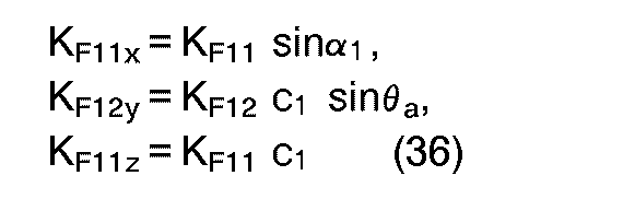


- With CFijkla defined by Equation (38), CFijika (i = 1, 2) of the same bearing portion shows a bias attraction ratio in veiw of Equation (29) and the condition (S2).
- Using the relationship of Equation (26), Equation (19), for example, is expressed by:

wherein
qy is then given by the following equation.
However,

- When indicating expressions of control forces are determined similarly, the overall linearized dynamic characteristics are summarized as given below.




- It is noted that:


- The control input variables are given by:


wherein

- In the case where the electromagnetic systems are equal in dynamic characteristics, the equations of motion can be expressed in separate forms using apparent input variables as described above. However, the control forces are influenced by the variation of gap length as will be apparent, for example, from Equations (46) and (51), and therefore interfere with each other through displacement. The interference is more complex than is the case with the arrangement of four electromagnets on one side.
- The systems of equations of motion determined above interfere with one another through displacement, whereas a single group of feedback systems, even when constructed neglecting the interference, will not encounter serious problems in actual use if a sufficiently great value can be selected as the gain of displacement. If the interference is not negligible, feedback of the displacement giving the interference can be added to the rule of control so as to diminish the interference. It therefore follows that use of the above apparent input variables makes it possible to approximately separate the design of the control system. How to determine the control inputs eij to the individual electromagnetic systems will be discussed below with reference to the rules of control for the motion systems given by the foregoing model.
- The actual control input variables are six in number, while the rotor motion is of a system of five degrees of freedom, so that one of them can be selected optionally. Although the control system can be handled generally as a multi-variable system, it is difficult to obtain useful standards for effectively utilizing excessive inputs. As in the foregoing paper, the optional selectivity is herein utilized in determining the proportions of the function of a thrust bearing to be performed by the respective two bearing portions.
- From the relationships of Equations (58) and (59), four actual input variables are expressed by:


wherein ey1 and ey2 are given by the following equations obtained from Equations (56).

eyz1 and eyz2 will be defined later. Further from Equations (57), e11 and e21 are expressed by: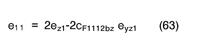

wherein

- The following variables are hereinafter used to summarize calculations of coefficients of the actual control inputs and for a better understanding of the features thereof.


- Equations (63), (60), (64) and (61) are then expressed by:


wherein the relationship of cF121b = 1/cF1112b is used. - The following relationship is obtained by substituting the relationships of Equations (67), (68) and (70) in Equation (55) of the x-axis direction control input variable.

eyz1' and eyz2' are to be replaced by the following expressions so as to establish the relationship of the above equation independently of the z-axis direction control inputs ez1 and ez2'. -




- When the control inputs ex, ey, eyR and ezR are determined, the inputs to the respective electromagnets are given by Equations (68) to (71) through the relationships of Equations (62a), (65a), (66), (67) and (73) as described above. These relationships are shown in the diagram of FIG. 3, in which u is used in place of e for the control input variables like ux in place of ex. The construction of this control system has the same features as in the case where eight electromagnets are used but is considerably more complex.
- As will be apparent from the above development, the coefficient terms of the coefficients k11, k21, ki2, k22 are necessary so that the axial control input will not be influenced by the z-axis direction control input. The former two and the latter two are in pairs, showing the ratio in which z-axis direction control is dividedly effected by the two bearing portions. Insofar as the foregoing relationships are satisfied, whatever coefficients selected theoretically produce no difference within the range of linearity, whereas in actual use, several standards are thought useful for the selection. For example, to make the control system simple in construction, k12 = k21 = 0 will be selected. Further it is possible to determine the distribution of control inputs with consideration given to the capacity of each electromagnet. When the bearing system is symmetric (cp12 = s12 = c12 =1), selection of k12 = k11, and k22 = k21 removes participation of ez from Equations (73), whereby the construction of the control system can be simplified to some extent. In this case, however, z-axis direction translation is to be controlled only by the two electromagnets to which e11 and e21 are input. This imposes limitations on the characteristics of the control system; for example, linearity is then liable to collapse because the transitional load on the electromagnets correspondingly increases. Incidentally, it is impossible to make Equations (73) free of participation of the z-axis direction rotation control input ezR because the rotor position angle is controlled by the moments of two control forces.
- The coefficients kx1 and kx2 indicate the proportions in which axial control is dividedly effected by the two bearing portions. Optional selection of one of these is the optional selection of one mentioned first in this chapter. Selection of one coefficient which is zero means that the function of an axial bearing is to be performed by one bearing portion. This means that the smallest possible actuator is used for controlling five degrees of freedom. It is relatively easy to determine the proportions of the functions of this axial bearing to be dividedly performed, with the operating conditions taken into consideration.
- Although the foregoing premise that all electromagnetic systems are equal in dynamic characteristics is not always satisfied generally, there appear fairly many cases where this proposition is fulfilled. Even if otherwise, phase compensation of the inputs to the electromagnetic systems will make it possible to render their characteristics approximate to a great extent. To ensure noninterference in this way is not a method wherein the characteristics peculiar to hardware are effectively utilized, but the interference-free system is easy to design with the load conditions taken into consideration, facilitates adjustment of parameters and therefore have great advantages.
- FIGS. 8 to 10 show a second embodiment. FIG. 8 shows an example of mechanical construction of the main part of a magnetic bearing device of the positive type, and FIG. 9 shows an example of electrical construction thereof. In the following description of the second embodiment, the terms front, rear, right, left, upper, lower, x-axis, y-axis and z-axis are defined with reference to FIG. 8 and have the same meanings as in the case of the first embodiment.
- The magnetic bearing device comprises a
rotary body 1 extending in the direction of x-axis, front and rear two radialmagnetic bearings rotary body 1 with respect to the radial direction, an axialmagnetic bearing 38 for contactlessly supporting therotary body 1 with respect to the axial direction, aradial control unit 39 for controlling the radialmagnetic bearings magnetic bearing 38, and displacement sensors for control. - The
rotary body 1 has straight (cylindrical) bearing faces 41, 42 formed respectively at front and rear two portions spaced apart axially of the body. At a suitable portion, e.g., front portion, therotary body 1 has anouter flange 43 for the axial bearing. - The front radial
magnetic bearing 36 comprises a front radial first electromagnet 44a disposed under and opposed to thefront bearing face 41, a front radialsecond electromagnet 44b disposed diagonally to the upper right of the bearingface 41 and opposed thereto, and a front radial third electromagnet 44c disposed diagonally to the upper left of the bearingface 41 and opposed thereto. Similarly, the rearmagnetic bearing 37 comprises a rear radialfirst electromagnet 45a, rear radialsecond electromagnet 45b and rear radialthird electromagnet 45c. These electromagnets 44a to 44c and 45a to 45c are in the same arrangement as in the first embodiment. - The axial
magnetic bearing 38 comprises an axialfirst electromagnet 46a and an axialsecond electromagnet 46b opposed to each other and arranged respectively on the rear and front sides of theflange 43 of therotary body 1. - The
radial control unit 39 comprises a z-axis directiontranslation control circuit 18, x-z plane inclinationmotion control circuit 21, y-axis directiontranslation control circuit 25, x-y plane inclinationmotion control circuit 27 and motion separatingcontrol circuit 47. - These
motion control circuits - FIG. 10 shows an example of construction of the motion separating
control circuit 47. In this case, radial control inputs Uz, UzR, Uy and uyR serve as control inputs to thecircuit 47. Based on these signals, the motion separatingcontrol circuit 47 produces electromagnet control signals e" , e12,el 3, e21 , e22, e23 like those in the first embodiment so as to separate the y-axis direction translation, x-y plane inclination motion, z-axis direction translation and x-z plane inclination motion of therotary body 1 from one another. Thiscircuit 47 corresponds to the motion separatingcontrol circuit 19 of the first embodiment as separated from Ux. Merely when thus modified, the circuit is made usable also for the radialmagnetic bearings - The axial control unit 40 produces an axial first electromagnet control signal e31 and an axial second electromagnet control signal e32 based on the x-axis displacement x of the center of gravity G of the
rotary body 1. The signal e31 is fed to a power amplifier 48 for driving the axialfirst electromagnet 46a, and the signal e32 to a power amplifier 49 for driving the axialsecond electromagnet 46b. - The second embodiment is the same as the first embodiment with the exception of the above features. Throughout the drawings showing the two embodiments, like parts are designated by like reference numerals or simbols.
- With the bearing device described, the radial
magnetic bearings magnetic bearing 28, so that no interference occurs between the radial motion and the axial motion. Theradial control unit 39 effects radial translation control for reducing the radial displacement of the center of gravity G of therotary body 1 to zero, and inclination motion control for reducing the amount of inclination of therotary body 1 about its center of gravity G to zero. Since these control operations are conducted separately from each other, the interference between radial motions can be eliminated. - The components of the magnetic bearing devices, such as means for determining the z-axis direction displacement z, amount of x-z plane inclination ZR, y-axis direction displacement y, amount of x-y plane inclination yR and x-axis direction displacement, are not limited to those of the above embodiments in construction but can be suitably modified.
- Although the axial bearing of the second embodiment is a magnetic bearing of the positive type wherein electromagnets are used, the axial bearing may comprise a magnetic bearing of the passive type wherein permanent magnets are used, or a mechanical bearing (such as roller bearing or slide bearing).
Claims (4)
Applications Claiming Priority (3)
| Application Number | Priority Date | Filing Date | Title |
|---|---|---|---|
| JP05032030A JP3131671B2 (en) | 1993-02-22 | 1993-02-22 | Magnetic bearing device |
| JP3203093 | 1993-02-22 | ||
| JP32030/93 | 1993-02-22 |
Publications (2)
| Publication Number | Publication Date |
|---|---|
| EP0612928A1 true EP0612928A1 (en) | 1994-08-31 |
| EP0612928B1 EP0612928B1 (en) | 2001-05-09 |
Family
ID=12347476
Family Applications (1)
| Application Number | Title | Priority Date | Filing Date |
|---|---|---|---|
| EP94102590A Expired - Lifetime EP0612928B1 (en) | 1993-02-22 | 1994-02-21 | Magnetic bearing device |
Country Status (3)
| Country | Link |
|---|---|
| EP (1) | EP0612928B1 (en) |
| JP (1) | JP3131671B2 (en) |
| DE (1) | DE69427171T2 (en) |
Cited By (13)
| Publication number | Priority date | Publication date | Assignee | Title |
|---|---|---|---|---|
| WO1997007340A1 (en) * | 1995-08-18 | 1997-02-27 | Sulzer Electronics Ag | Magnetic bearing and process for operating it |
| WO1997008477A3 (en) * | 1995-08-31 | 1997-08-14 | Clouth Gummiwerke Ag | System for actively reducing radial vibrations in a rotating shaft, and method of operating the system to achieve this |
| US6138629A (en) * | 1995-08-31 | 2000-10-31 | Isad Electronic Systems Gmbh & Co. Kg | System for actively reducing radial vibrations in a rotating shaft, and method of operating the system to achieve this |
| US6149544A (en) * | 1995-08-31 | 2000-11-21 | Isad Electronic Systems Gmbh & Co. Kg | Drive system for a motor vehicle with a drive unit and electric machine, and method of operating the system |
| US6148784A (en) * | 1995-08-31 | 2000-11-21 | Isad Electronic Systems Gmbh & Co. Kg | Drive systems, especially for a motor vehicle, and method of operating same |
| US6158405A (en) * | 1995-08-31 | 2000-12-12 | Isad Electronic Systems | System for actively reducing rotational nonuniformity of a shaft, in particular, the drive shaft of an internal combustion engine, and method of operating the system |
| US6487998B1 (en) | 1995-08-31 | 2002-12-03 | Isad Electronic Systems Gmbh & Co., Kg | Drive system, particularly for a motor vehicle, and process for operating it |
| EP0845084B1 (en) * | 1995-08-18 | 2004-03-03 | LUST ANTRIEBSTECHNIK GmbH | Radial active magnetic bearing device and process for operating it |
| EP3046249A4 (en) * | 2013-09-12 | 2017-05-31 | National Engineering Research Center Of Green Refrigeration Equipment | Shaft control method and device for magnetic suspension system |
| CN107327487A (en) * | 2017-08-29 | 2017-11-07 | 南京磁谷科技有限公司 | A kind of U-shaped field structure of sloping magnetic poles magnetic bearing |
| CN114810825A (en) * | 2022-03-30 | 2022-07-29 | 清华大学 | Magnetic bearing, control method and device |
| CN115182928A (en) * | 2022-03-28 | 2022-10-14 | 北方工业大学 | A dynamic friction reduction method for composite shaft boresight stabilization equipment |
| CN117739013A (en) * | 2024-02-21 | 2024-03-22 | 中国人民解放军海军工程大学 | A shielded magnetic bearing system for marine fluid machinery |
Families Citing this family (2)
| Publication number | Priority date | Publication date | Assignee | Title |
|---|---|---|---|---|
| DE19532129A1 (en) | 1995-08-31 | 1997-03-06 | Clouth Gummiwerke Ag | System for actively reducing rotational irregularities of a shaft, in particular the drive shaft of an internal combustion engine, and method therefor |
| CN105092424B (en) * | 2015-07-22 | 2018-01-12 | 中国环境科学研究院 | Asphalt concrete pavement rain penetration analogue means |
Citations (2)
| Publication number | Priority date | Publication date | Assignee | Title |
|---|---|---|---|---|
| US3155437A (en) * | 1953-05-21 | 1964-11-03 | North American Aviation Inc | Electromagnetic bearing |
| JPS6152411A (en) * | 1984-08-22 | 1986-03-15 | Yaskawa Electric Mfg Co Ltd | Control device for magnetic bearing device |
Family Cites Families (1)
| Publication number | Priority date | Publication date | Assignee | Title |
|---|---|---|---|---|
| JPH0297714A (en) * | 1988-10-04 | 1990-04-10 | Seiko Seiki Co Ltd | Control device for magnetic floating body |
-
1993
- 1993-02-22 JP JP05032030A patent/JP3131671B2/en not_active Expired - Fee Related
-
1994
- 1994-02-21 EP EP94102590A patent/EP0612928B1/en not_active Expired - Lifetime
- 1994-02-21 DE DE1994627171 patent/DE69427171T2/en not_active Expired - Lifetime
Patent Citations (2)
| Publication number | Priority date | Publication date | Assignee | Title |
|---|---|---|---|---|
| US3155437A (en) * | 1953-05-21 | 1964-11-03 | North American Aviation Inc | Electromagnetic bearing |
| JPS6152411A (en) * | 1984-08-22 | 1986-03-15 | Yaskawa Electric Mfg Co Ltd | Control device for magnetic bearing device |
Non-Patent Citations (2)
| Title |
|---|
| A. M. MOHAMED AND F.P. EMAD: "Conical magnetic bearings with radial and thrust control", PROCEEDINGS OF THE 28TH IEEE CONFERENCE ON DECISION AND CONTROL, vol. 1, 13 December 1989 (1989-12-13), TAMPA , US, pages 554 - 561 * |
| PATENT ABSTRACTS OF JAPAN vol. 10, no. 211 (M - 501)<2267> 24 July 1986 (1986-07-24) * |
Cited By (17)
| Publication number | Priority date | Publication date | Assignee | Title |
|---|---|---|---|---|
| WO1997007340A1 (en) * | 1995-08-18 | 1997-02-27 | Sulzer Electronics Ag | Magnetic bearing and process for operating it |
| EP0845084B1 (en) * | 1995-08-18 | 2004-03-03 | LUST ANTRIEBSTECHNIK GmbH | Radial active magnetic bearing device and process for operating it |
| US6130494A (en) * | 1995-08-18 | 2000-10-10 | Sulzer Electroncis Ag | Magnetic bearing apparatus and a method for operating the same |
| US6149544A (en) * | 1995-08-31 | 2000-11-21 | Isad Electronic Systems Gmbh & Co. Kg | Drive system for a motor vehicle with a drive unit and electric machine, and method of operating the system |
| US6148784A (en) * | 1995-08-31 | 2000-11-21 | Isad Electronic Systems Gmbh & Co. Kg | Drive systems, especially for a motor vehicle, and method of operating same |
| US6158405A (en) * | 1995-08-31 | 2000-12-12 | Isad Electronic Systems | System for actively reducing rotational nonuniformity of a shaft, in particular, the drive shaft of an internal combustion engine, and method of operating the system |
| US6487998B1 (en) | 1995-08-31 | 2002-12-03 | Isad Electronic Systems Gmbh & Co., Kg | Drive system, particularly for a motor vehicle, and process for operating it |
| WO1997008477A3 (en) * | 1995-08-31 | 1997-08-14 | Clouth Gummiwerke Ag | System for actively reducing radial vibrations in a rotating shaft, and method of operating the system to achieve this |
| US6138629A (en) * | 1995-08-31 | 2000-10-31 | Isad Electronic Systems Gmbh & Co. Kg | System for actively reducing radial vibrations in a rotating shaft, and method of operating the system to achieve this |
| US10253809B2 (en) | 2013-09-12 | 2019-04-09 | Green Refrigeration Equipment Engineering Research Center Of Zhuhai Gree Co., Ltd. | Shaft control method and device for magnetic suspension system |
| EP3046249A4 (en) * | 2013-09-12 | 2017-05-31 | National Engineering Research Center Of Green Refrigeration Equipment | Shaft control method and device for magnetic suspension system |
| CN107327487A (en) * | 2017-08-29 | 2017-11-07 | 南京磁谷科技有限公司 | A kind of U-shaped field structure of sloping magnetic poles magnetic bearing |
| CN115182928A (en) * | 2022-03-28 | 2022-10-14 | 北方工业大学 | A dynamic friction reduction method for composite shaft boresight stabilization equipment |
| CN115182928B (en) * | 2022-03-28 | 2023-08-11 | 北方工业大学 | A Dynamic Friction Reduction Method for Composite Axis Stabilization Equipment |
| CN114810825A (en) * | 2022-03-30 | 2022-07-29 | 清华大学 | Magnetic bearing, control method and device |
| CN117739013A (en) * | 2024-02-21 | 2024-03-22 | 中国人民解放军海军工程大学 | A shielded magnetic bearing system for marine fluid machinery |
| CN117739013B (en) * | 2024-02-21 | 2024-05-17 | 中国人民解放军海军工程大学 | A shielded magnetic bearing system for marine fluid machinery |
Also Published As
| Publication number | Publication date |
|---|---|
| DE69427171D1 (en) | 2001-06-13 |
| DE69427171T2 (en) | 2001-11-15 |
| JP3131671B2 (en) | 2001-02-05 |
| EP0612928B1 (en) | 2001-05-09 |
| JPH06249238A (en) | 1994-09-06 |
Similar Documents
| Publication | Publication Date | Title |
|---|---|---|
| EP0612928B1 (en) | Magnetic bearing device | |
| EP0620376B1 (en) | Magnetic bearing apparatus | |
| EP0087628B1 (en) | Magnetic bearing wheel for an artificial satellite | |
| US4882837A (en) | Precision automatic assembly apparatus including face to face magnets and an air core coil therebetween | |
| Hsu et al. | Nonlinear control of a 3-pole active magnetic bearing system | |
| EP0253615A2 (en) | Magnetic isolating and pointing gimbal apparatus | |
| Sabnis et al. | A magnetically suspended large momentum wheel | |
| CN113280042B (en) | Control device and method of magnetic suspension bearing and magnetic suspension system | |
| WO2007026270A1 (en) | Ironless magnetic linear motors having levitating and transversal force capacities | |
| EP0023958B1 (en) | Free rotor gas-bearing gyroscope having electro-magnetic rotor restraint and acceleration output signal and method of operating a gyroscope | |
| Zhou et al. | One-axis hysteresis motor driven magnetically suspended reaction sphere | |
| Wen et al. | The airborne inertially stabilized platform suspend by an axial-radial integrated active magnetic actuator system | |
| US5763972A (en) | Magnetic bearing with alternating actuators and sensors | |
| Yao et al. | A dual-loop control approach of active magnetic bearing system for rotor tracking control | |
| Tang et al. | Rotor׳ s Suspension for Vernier-gimballing magnetically suspended flywheel with conical magnetic bearing | |
| JPH07238928A (en) | Magnetic bearing device | |
| WO1990001122A1 (en) | Electromagnetic bearings | |
| Geng et al. | Sliding mode control based on linear quadratic regulator for an active magnetic bearing flexible rotor virtual collocated system | |
| US20150145363A1 (en) | Magnetic wheel bearing | |
| Liebfrieda et al. | Performance of Flux Density Based Control Approaches for Active Magnetic Bearings–an Overview | |
| Vitner et al. | Experimental verification of the hybrid magnetic bearing operation | |
| EP1701050A1 (en) | Power amplification device and magnetic bearing | |
| US20260005557A1 (en) | Electromagnetic rotary machinery | |
| KR100355390B1 (en) | Non-Colocation Compensation Method and Compensation Circuit of Magnetic Bearing System | |
| Behrens et al. | Dynamic and robust control of a 5-DoF active magnetic Lorentz-force bearing for space applications |
Legal Events
| Date | Code | Title | Description |
|---|---|---|---|
| PUAI | Public reference made under article 153(3) epc to a published international application that has entered the european phase |
Free format text: ORIGINAL CODE: 0009012 |
|
| AK | Designated contracting states |
Kind code of ref document: A1 Designated state(s): CH DE FR GB LI |
|
| 17P | Request for examination filed |
Effective date: 19950207 |
|
| 17Q | First examination report despatched |
Effective date: 19970611 |
|
| GRAG | Despatch of communication of intention to grant |
Free format text: ORIGINAL CODE: EPIDOS AGRA |
|
| GRAG | Despatch of communication of intention to grant |
Free format text: ORIGINAL CODE: EPIDOS AGRA |
|
| GRAH | Despatch of communication of intention to grant a patent |
Free format text: ORIGINAL CODE: EPIDOS IGRA |
|
| GRAH | Despatch of communication of intention to grant a patent |
Free format text: ORIGINAL CODE: EPIDOS IGRA |
|
| GRAH | Despatch of communication of intention to grant a patent |
Free format text: ORIGINAL CODE: EPIDOS IGRA |
|
| GRAH | Despatch of communication of intention to grant a patent |
Free format text: ORIGINAL CODE: EPIDOS IGRA |
|
| GRAA | (expected) grant |
Free format text: ORIGINAL CODE: 0009210 |
|
| AK | Designated contracting states |
Kind code of ref document: B1 Designated state(s): CH DE FR GB LI |
|
| REG | Reference to a national code |
Ref country code: CH Ref legal event code: NV Representative=s name: PATENTANWALTSBUERO JEAN HUNZIKER Ref country code: CH Ref legal event code: EP |
|
| REF | Corresponds to: |
Ref document number: 69427171 Country of ref document: DE Date of ref document: 20010613 |
|
| ET | Fr: translation filed | ||
| REG | Reference to a national code |
Ref country code: GB Ref legal event code: IF02 |
|
| PLBE | No opposition filed within time limit |
Free format text: ORIGINAL CODE: 0009261 |
|
| STAA | Information on the status of an ep patent application or granted ep patent |
Free format text: STATUS: NO OPPOSITION FILED WITHIN TIME LIMIT |
|
| 26N | No opposition filed | ||
| PGFP | Annual fee paid to national office [announced via postgrant information from national office to epo] |
Ref country code: GB Payment date: 20080220 Year of fee payment: 15 |
|
| GBPC | Gb: european patent ceased through non-payment of renewal fee |
Effective date: 20090221 |
|
| PG25 | Lapsed in a contracting state [announced via postgrant information from national office to epo] |
Ref country code: GB Free format text: LAPSE BECAUSE OF NON-PAYMENT OF DUE FEES Effective date: 20090221 |
|
| PGFP | Annual fee paid to national office [announced via postgrant information from national office to epo] |
Ref country code: CH Payment date: 20120214 Year of fee payment: 19 Ref country code: FR Payment date: 20120221 Year of fee payment: 19 |
|
| PGFP | Annual fee paid to national office [announced via postgrant information from national office to epo] |
Ref country code: DE Payment date: 20120215 Year of fee payment: 19 |
|
| REG | Reference to a national code |
Ref country code: CH Ref legal event code: PL |
|
| PG25 | Lapsed in a contracting state [announced via postgrant information from national office to epo] |
Ref country code: LI Free format text: LAPSE BECAUSE OF NON-PAYMENT OF DUE FEES Effective date: 20130228 Ref country code: CH Free format text: LAPSE BECAUSE OF NON-PAYMENT OF DUE FEES Effective date: 20130228 |
|
| REG | Reference to a national code |
Ref country code: FR Ref legal event code: ST Effective date: 20131031 |
|
| REG | Reference to a national code |
Ref country code: DE Ref legal event code: R119 Ref document number: 69427171 Country of ref document: DE Effective date: 20130903 |
|
| PG25 | Lapsed in a contracting state [announced via postgrant information from national office to epo] |
Ref country code: FR Free format text: LAPSE BECAUSE OF NON-PAYMENT OF DUE FEES Effective date: 20130228 Ref country code: DE Free format text: LAPSE BECAUSE OF NON-PAYMENT OF DUE FEES Effective date: 20130903 |