EP0612427B1 - A device for holding strip-like information carriers - Google Patents
A device for holding strip-like information carriers Download PDFInfo
- Publication number
- EP0612427B1 EP0612427B1 EP92924074A EP92924074A EP0612427B1 EP 0612427 B1 EP0612427 B1 EP 0612427B1 EP 92924074 A EP92924074 A EP 92924074A EP 92924074 A EP92924074 A EP 92924074A EP 0612427 B1 EP0612427 B1 EP 0612427B1
- Authority
- EP
- European Patent Office
- Prior art keywords
- holder
- channel
- information
- pin
- Prior art date
- Legal status (The legal status is an assumption and is not a legal conclusion. Google has not performed a legal analysis and makes no representation as to the accuracy of the status listed.)
- Expired - Lifetime
Links
- 239000000969 carrier Substances 0.000 title claims abstract description 7
- 239000000463 material Substances 0.000 claims description 5
- 230000005484 gravity Effects 0.000 claims description 4
- 229920003023 plastic Polymers 0.000 claims description 3
- 229920002457 flexible plastic Polymers 0.000 claims description 2
- 238000000465 moulding Methods 0.000 claims description 2
- 230000008901 benefit Effects 0.000 description 3
- 230000009286 beneficial effect Effects 0.000 description 2
- 230000008859 change Effects 0.000 description 1
- 238000004519 manufacturing process Methods 0.000 description 1
- 230000007246 mechanism Effects 0.000 description 1
- 230000004048 modification Effects 0.000 description 1
- 238000012986 modification Methods 0.000 description 1
Images
Classifications
-
- A—HUMAN NECESSITIES
- A47—FURNITURE; DOMESTIC ARTICLES OR APPLIANCES; COFFEE MILLS; SPICE MILLS; SUCTION CLEANERS IN GENERAL
- A47F—SPECIAL FURNITURE, FITTINGS, OR ACCESSORIES FOR SHOPS, STOREHOUSES, BARS, RESTAURANTS OR THE LIKE; PAYING COUNTERS
- A47F5/00—Show stands, hangers, or shelves characterised by their constructional features
- A47F5/08—Show stands, hangers, or shelves characterised by their constructional features secured to the wall, ceiling, or the like; Wall-bracket display devices
- A47F5/0807—Display panels, grids or rods used for suspending merchandise or cards supporting articles; Movable brackets therefor
- A47F5/0869—Accessories for article-supporting brackets, e.g. price- indicating means, not covered by a single one of groups A47F5/08
Definitions
- the present invention relates to a holder for strip-like information carriers intended for use in self-service stores, shops and like establishments for use in conjunction with goods displaced on a pronged rack and comprising a holder part which is intended to be fitted to the rack and an information-carrier receiving part which is connected to the first mentioned holder part.
- Effective and efficient holders are known which can be fitted to the front edge surfaces of shelving, wire cages or baskets and the like in shops and stores, and which carry information strips relating to the goods displayed.
- the information should be presented on labels of normal size placed on the forward ends of the prongs as, for example, is shown in US-A-4 540 093 . It is also beneficial to store personnel when one and the same label size can be used in all instances.
- One problem resides in the provision of a holder for labels of this kind which will not obstruct removal of packaged articles or other goods from the prongs. This is particularly difficult to achieve when the labels are placed forwardly of the ends of the prongs. Labels which are fitted above the prongs encroach on expensive display space.
- the main object of the present invention is to provide a holder for strip-like information carriers which is intended for use with pronged racks and which eliminates the aforesaid drawbacks, among other things.
- the holder part which is intended to receive an information carrier is mounted forwardly of the front ends of the prong and can be swung-up when removing articles from the prong or prongs of the rack structure.
- a holder is provided which is defined in the independent claim 1.
- a holder of this kind has the advantage of enabling standard-sized labels to be used and placed in a position in which the information thereon can be read easily by the customer. Another advantage is that no additional space is required for the holder. Furthermore, the pocket can be opened very easily, which greatly facilitates the exchange of labels.
- a preferred embodiment of an inventive holder is characterized in that the pocket is transparent; in that at least a portion of the upper part of the rear wall of the pocket is folded rearwardly to form a downwardly open cylindrical channel; and in that the forward end of the cantilever arm is provided with a transversal pivot-pin which coacts with said channel.
- the channel opening is somewhat narrower than the pivot-pin, so as to enable the pin to be pressed into the channel while flexing the channel wall outwards to some extent, so as to hold the pin in the channel when the channel wall returns to its original position.
- the pocket can only be swung to a limited extent, so that the pocket will always return to its normal, downwardly swung position under the influence of gravity.
- the angle through which the pocket can be swung is limited to about 90°.
- Figure 1 is a perspective view of an inventive holder.
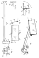
- Figures 2 and 3 are respectively a front view and a side view of the part of the holder intended to receive an information carrier.
- Figure 4 is a side view of the holder and the cantilever arm, and Figure 4A is a view from above of the forward end of the arm.
- Figure 5 is a front view of the arm shown in Figure 4.
- Figure 6 illustrates the pocket-raising function of the inventive holder.
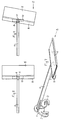
- Figure 7 is a view from above showing the pocket in a raised position.
- Figures 8 and 9 are views of the holder from below and show the holder pocket in a normal position and in a latched position respectively.
- the holder shown in Figure 1 includes a mounting part 1 which is intended to be fitted onto two mutually parallel prongs (not shown), said prongs being accommodated in a respective one of two slotted grooves 2 and 3.
- the grooves are configured so as to enable the mounting part to be fixed to prongs of varying diameters.
- the invention can be applied with other types of mounts, for instance mounts which are intended to be fitted solely to one prong or to a prong of non-round cross-section.
- the illustrated holder also includes a cantilever arm 4 which extends out from the mounting part 1 and which has mounted on its forward end a part 5 which is intended to receive a strip-like information carrier.
- the holder part 5 has the form of a pocket which is made of flexible, transparent plastic material and which is open along the upper edge thereof.
- the bottom edge of the front wall of the pocket 5 is bent out to form a longitudinally extending ledge 6 along which an electronic reading device can be guided.
- the upper edge of the front wall of the pocket 5 is protected beneath a projection 7 that extends from the rear wall of the pocket.
- a folded arcuate part 8 which has an essentially cylindrical inner surface.
- the part 8 forms a downwardly open channel along the upper edge of said pocket. Punched in the part 8 is a slot 9 whose function will be described below.
- the front end of the arm 4 carries a transverse, cylindrical pivot-pin 10, which in the case of the illustrated embodiment is an integral part of the arm 4 and thus fixed in relation thereto.
- the arm is also provided with a downwardly projecting part 11 which functions to support the rear wall of the pocket 5.
- the supporting part 11 does not extend down to the bottom edge of the pocket 5, but terminates approximately in the centre of the pocket.
- Figure 5 is a front view of the arm 4, the pivot-pin 10 and the holder 1 shown in Figure 4.
- the pocket 5 is fitted to the pin 10 by pressing the pocket downwards so as to force that part of the pocket structure which forms the channel onto the pin 10 while flexing the channel wall outwards.
- the pocket is pivotally locked to the pin 10. If the pocket should become damaged, the pocket 5 can be readily replaced correspondingly.
- the mounting part 1 is fitted onto the inwardly lying parts of two prongs projecting from a rack, said prongs being received in the slots 2 and 3.
- the pocket 5 intended to receive information-carrying labels relating to the articles displayed on the prongs is therewith located forwardly of the prong ends, so as to enable the labels to be easily read and clearly disclosing to which goods the label refers.
- This upward swinging of the pocket 5 is made possible by means of the aforementioned slot 9 provided in the holder part 8 and receiving the cantilever arm 4.
- the extent to which the pocket is able to swing upwards can be limited by commensurate limitation of the depth of the slot 9.
- This upward movement of the pocket is suitably limited to an angle of about 90°.
- slot 9 Another important advantage provided by the slot 9 is that it functions automatically to centre the pocket 5 and hold said pocket in its correct position on the pivot-pin 4, the pocket being prevented from moving sideways as a result of the coaction between the slot 9 and the arm 4.
- the illustrated hinge mechanism which is extremely simple and cheap to manufacture, also provides a very simple stop means which prevents over-rotation of the pocket as the pocket is raised, and also a simple and effective means for locking the pocket against sideways movement.
- the support part 11 of the arm 4 which supports against the rear wall of the pocket 5 also enables the pocket to be readily opened in order to change respective information-carrying labels.
- the store personnel need only press on the front wall of the pocket 5, in the direction of the arrow A in Figure 6, this pressure causing the upper edge of the pocket to open due to the coaction with the rearwardly-lying supporting part 11, as will readily be understood.
- the pocket 5 can easily be held in an upwardly swung position, which is highly beneficial to the store personnel concerned, for instance when hanging further packaged articles or goods on the prongs of the rack. All that is necessary in this regard is to press the pocket in the direction of the arrow B in Figure 7 in the upwardly swung position of said pocket.
- the pivot-pin 10 is therewith partially pressed out from the channel formed by the part 8, therewith preventing the pocket from swinging down to a vertical position until the pivot-pin has again been pressed into the channel.
- a holder of the aforedescribed kind can be produced very easily, since the pocket 5 and the pivot-pin receiving channel 8 may consist of one part of a long, extruded profiled strip produced from a flexible plastic material, whereas the cantilever arm 4, the mounting part 1 and the fixed pivot-pin 10 may be produced as a one-piece structure, by pressure-moulding a rigid plastic material.
- the inventive holder can be easily assembled by the purchaser, therewith reducing both the requisite transporting space and storage space.
- the channel which extends along the rear pocket wall may be replaced with one or more shorter, channel-shaped parts which coact with a pivot pin 10 of desired length.
- the forward end of the arm 4 may be provided with more than one pocket supporting part 11, if so desired.
Landscapes
- Supports Or Holders For Household Use (AREA)
- Vehicle Step Arrangements And Article Storage (AREA)
- Packaging For Recording Disks (AREA)
- Magnetic Record Carriers (AREA)
- Package Frames And Binding Bands (AREA)
- Radar Systems Or Details Thereof (AREA)
- Credit Cards Or The Like (AREA)
- Transition And Organic Metals Composition Catalysts For Addition Polymerization (AREA)
- Diaphragms For Electromechanical Transducers (AREA)
- Purses, Travelling Bags, Baskets, Or Suitcases (AREA)
Abstract
Description
- The present invention relates to a holder for strip-like information carriers intended for use in self-service stores, shops and like establishments for use in conjunction with goods displaced on a pronged rack and comprising a holder part which is intended to be fitted to the rack and an information-carrier receiving part which is connected to the first mentioned holder part.
- Effective and efficient holders are known which can be fitted to the front edge surfaces of shelving, wire cages or baskets and the like in shops and stores, and which carry information strips relating to the goods displayed.
- On the other hand, it has been more difficult to produce inexpensive and effective holder means for information carriers which disclose information concerning goods and articles that are displayed for sale on pronged racks, for instance packaged articles displayed on long, substantially horizontal prongs.
- In order to enable customers to read the information disclosed, the information should be presented on labels of normal size placed on the forward ends of the prongs as, for example, is shown in US-A-4 540 093 . It is also beneficial to store personnel when one and the same label size can be used in all instances. One problem, however, resides in the provision of a holder for labels of this kind which will not obstruct removal of packaged articles or other goods from the prongs. This is particularly difficult to achieve when the labels are placed forwardly of the ends of the prongs. Labels which are fitted above the prongs encroach on expensive display space. Furthermore, it is desirable to eliminate the need to use separate, empty prongs solely as label or tag carriers.
The main object of the present invention is to provide a holder for strip-like information carriers which is intended for use with pronged racks and which eliminates the aforesaid drawbacks, among other things. - This object is achieved in accordance with the present invention in that the holder part, which is intended to receive an information carrier is mounted forwardly of the front ends of the prong and can be swung-up when removing articles from the prong or prongs of the rack structure.
- According to the present invention, a holder is provided which is defined in the independent claim 1.
- A holder of this kind has the advantage of enabling standard-sized labels to be used and placed in a position in which the information thereon can be read easily by the customer. Another advantage is that no additional space is required for the holder. Furthermore, the pocket can be opened very easily, which greatly facilitates the exchange of labels.
- A preferred embodiment of an inventive holder is characterized in that the pocket is transparent; in that at least a portion of the upper part of the rear wall of the pocket is folded rearwardly to form a downwardly open cylindrical channel; and in that the forward end of the cantilever arm is provided with a transversal pivot-pin which coacts with said channel. The channel opening is somewhat narrower than the pivot-pin, so as to enable the pin to be pressed into the channel while flexing the channel wall outwards to some extent, so as to hold the pin in the channel when the channel wall returns to its original position.
- It is preferred that the pocket can only be swung to a limited extent, so that the pocket will always return to its normal, downwardly swung position under the influence of gravity. To this end, there is conveniently formed in the channel wall a slot which receives the cantilever arm when the pocket is swung upwardly, the depth of the slot being adapted to limit the extent to which said part can be swung up. Preferably, the angle through which the pocket can be swung is limited to about 90°.
- The invention will now be described in more detail with reference to an exemplifying embodiment thereof and also with reference to the accompanying drawings.
- Figure 1 is a perspective view of an inventive holder.
- Figures 2 and 3 are respectively a front view and a side view of the part of the holder intended to receive an information carrier.
- Figure 4 is a side view of the holder and the cantilever arm, and Figure 4A is a view from above of the forward end of the arm.
- Figure 5 is a front view of the arm shown in Figure 4.
- Figure 6 illustrates the pocket-raising function of the inventive holder.
- Figure 7 is a view from above showing the pocket in a raised position.
- Figures 8 and 9 are views of the holder from below and show the holder pocket in a normal position and in a latched position respectively.
- The holder shown in Figure 1 includes a mounting part 1 which is intended to be fitted onto two mutually parallel prongs (not shown), said prongs being accommodated in a respective one of two slotted
grooves - The illustrated holder also includes a
cantilever arm 4 which extends out from the mounting part 1 and which has mounted on its forward end apart 5 which is intended to receive a strip-like information carrier. - As will be seen also from Figures 2 and 3, the
holder part 5 has the form of a pocket which is made of flexible, transparent plastic material and which is open along the upper edge thereof. The bottom edge of the front wall of thepocket 5 is bent out to form a longitudinally extendingledge 6 along which an electronic reading device can be guided. The upper edge of the front wall of thepocket 5 is protected beneath aprojection 7 that extends from the rear wall of the pocket. - Extending along the upper edge of the rear pocket wall is a folded
arcuate part 8 which has an essentially cylindrical inner surface. Thepart 8 forms a downwardly open channel along the upper edge of said pocket. Punched in thepart 8 is aslot 9 whose function will be described below. - As will be seen from Figures 4 and 4A, the front end of the
arm 4 carries a transverse, cylindrical pivot-pin 10, which in the case of the illustrated embodiment is an integral part of thearm 4 and thus fixed in relation thereto. The arm is also provided with a downwardly projectingpart 11 which functions to support the rear wall of thepocket 5. The supportingpart 11 does not extend down to the bottom edge of thepocket 5, but terminates approximately in the centre of the pocket. - Figure 5 is a front view of the
arm 4, the pivot-pin 10 and the holder 1 shown in Figure 4. - The
pocket 5 is fitted to thepin 10 by pressing the pocket downwards so as to force that part of the pocket structure which forms the channel onto thepin 10 while flexing the channel wall outwards. When the channel wall returns to its normal position, the pocket is pivotally locked to thepin 10. If the pocket should become damaged, thepocket 5 can be readily replaced correspondingly. - Thus, when using the illustrated device, the mounting part 1 is fitted onto the inwardly lying parts of two prongs projecting from a rack, said prongs being received in the
slots pocket 5 intended to receive information-carrying labels relating to the articles displayed on the prongs is therewith located forwardly of the prong ends, so as to enable the labels to be easily read and clearly disclosing to which goods the label refers. When a packaged article, which may be threaded onto the prongs, is removed from the prongs, thepocket 5 will swing upwards from the position shown in full lines in Figure 6 to the position shown in broken lines, thereby enabling the packaged article to be removed without being obstructed by the pocket. See also Figure 7. Upon removal of the packaged article, the pocket will automatically swing down under the force of gravity. - This upward swinging of the
pocket 5 is made possible by means of theaforementioned slot 9 provided in theholder part 8 and receiving thecantilever arm 4. The extent to which the pocket is able to swing upwards can be limited by commensurate limitation of the depth of theslot 9. This upward movement of the pocket is suitably limited to an angle of about 90°. - Another important advantage provided by the
slot 9 is that it functions automatically to centre thepocket 5 and hold said pocket in its correct position on the pivot-pin 4, the pocket being prevented from moving sideways as a result of the coaction between theslot 9 and thearm 4. - Thus, the illustrated hinge mechanism, which is extremely simple and cheap to manufacture, also provides a very simple stop means which prevents over-rotation of the pocket as the pocket is raised, and also a simple and effective means for locking the pocket against sideways movement.
- The
support part 11 of thearm 4 which supports against the rear wall of thepocket 5 also enables the pocket to be readily opened in order to change respective information-carrying labels. Thus, the store personnel need only press on the front wall of thepocket 5, in the direction of the arrow A in Figure 6, this pressure causing the upper edge of the pocket to open due to the coaction with the rearwardly-lying supportingpart 11, as will readily be understood. - Further, the
pocket 5 can easily be held in an upwardly swung position, which is highly beneficial to the store personnel concerned, for instance when hanging further packaged articles or goods on the prongs of the rack. All that is necessary in this regard is to press the pocket in the direction of the arrow B in Figure 7 in the upwardly swung position of said pocket. As will be seen when comparing Figure 8 with Figure 9, the pivot-pin 10 is therewith partially pressed out from the channel formed by thepart 8, therewith preventing the pocket from swinging down to a vertical position until the pivot-pin has again been pressed into the channel. - A holder of the aforedescribed kind can be produced very easily, since the
pocket 5 and the pivot-pin receivingchannel 8 may consist of one part of a long, extruded profiled strip produced from a flexible plastic material, whereas thecantilever arm 4, the mounting part 1 and the fixed pivot-pin 10 may be produced as a one-piece structure, by pressure-moulding a rigid plastic material. The inventive holder can be easily assembled by the purchaser, therewith reducing both the requisite transporting space and storage space. - Although the inventive holder has been described with reference to a preferred exemplifying embodiment thereof, it will be understood that modifications and changes can be made within the scope of the following Claims. For instance, the channel which extends along the rear pocket wall may be replaced with one or more shorter, channel-shaped parts which coact with a
pivot pin 10 of desired length. Furthermore, the forward end of thearm 4 may be provided with more than onepocket supporting part 11, if so desired.
Claims (8)
- A holder for strip-like information carriers intended for use in shops, stores and like establishments in conjunction with goods and articles that are displayed on pronged racks, said holder comprising a mounting part (1) which is intended to be fitted to elongated prongs and a part (5) which is connected to the mounting part (1) and which is intended to accommodate said information carrier, wherein the mounting part (1) is intended to be secured to the inner part of at least one prong and is provided with a cantilever arm (4) which extends above and essentially parallel with said prong; in that the information-carrier receiving part of the holder has the form of a pocket (5) which is open along the upper edge thereof; in that the pocket is so mounted on the forward end of the cantilever arm (4) as to enable the pocket to swing upwardly as an article is removed from the prong; and in that the forward end of the arm (4) has at least one supporting part (11) which bears against the rear wall of the pocket (5) so that when said pocket is in a downwardly swung position, the pocket can be opened by pressing against the lower part of the front wall of the pocket.
- A holder according to Claim 1, characterized in that the upward swinging movement of the information-carrier receiving pocket (5) is limited, so that it is always able to return to its normal, downwardly swung position under the influence of gravity.
- A holder according to Claim 1 or 2, characterized in that the pocket (5) is transparent; in that at least one part (8) of the upper part of the rear pocket wall is folded rearwardly to form a downwardly open, cylindrical channel; and in that the forward end of the cantilever arm (4) has a transversely extending pivot-pin (10) which coacts with the channel.
- A holder according to Claim 3, characterized in that the cross-dimension of the channel opening is somewhat smaller than the cross-dimension of the pivot-pin (10); and in that the pin can be pressed into the channel while flexing the channel wall slightly outwards, so that the pivot pin will be held securely in the channel as the wall returns to its original position.
- A holder according to Claim 3 or 4, characterized in that the channel wall (8) is provided with a slot (9) which receives the cantilever arm (4) when the information-carrier receiving pocket (5) is swung up; and in that the depth of the slot (9) is adapted to limit upward swinging of the pocket (5) such as to allow said pocket to return to a downwardly-depending position under the influence of gravity.
- A holder according to Claim 5, characterized in the depth of the slot (9) is chosen so that the pocket (5) can be swung up through an angle of about 90°.
- A holder according to any one of Claims 1-6, characterized in that the pocket (5) is an integral part of an extruded profiled section of flexible plastic material.
- A holder according to any one of Claims 1-7, characterized in that the mounting part (1), the cantilever arm (4) and the pivot-pin (10) fixedly joined to the arm (4) form a one-piece structure produced preferably by pressure-moulding a rigid plastic material.
Applications Claiming Priority (3)
| Application Number | Priority Date | Filing Date | Title |
|---|---|---|---|
| SE9103326A SE469201B (en) | 1991-11-12 | 1991-11-12 | TELLER FOR CORRESPONDING INFORMATION BEARERS |
| SE9103326 | 1991-11-12 | ||
| PCT/SE1992/000776 WO1993010516A1 (en) | 1991-11-12 | 1992-11-11 | A device for holding strip-like information carriers |
Publications (2)
| Publication Number | Publication Date |
|---|---|
| EP0612427A1 EP0612427A1 (en) | 1994-08-31 |
| EP0612427B1 true EP0612427B1 (en) | 1997-04-23 |
Family
ID=20384295
Family Applications (1)
| Application Number | Title | Priority Date | Filing Date |
|---|---|---|---|
| EP92924074A Expired - Lifetime EP0612427B1 (en) | 1991-11-12 | 1992-11-11 | A device for holding strip-like information carriers |
Country Status (10)
| Country | Link |
|---|---|
| US (1) | US5442872A (en) |
| EP (1) | EP0612427B1 (en) |
| JP (1) | JPH07501157A (en) |
| AT (1) | ATE152276T1 (en) |
| CA (1) | CA2119868A1 (en) |
| DE (1) | DE69219353T2 (en) |
| FI (1) | FI102326B (en) |
| NO (1) | NO304205B1 (en) |
| SE (1) | SE469201B (en) |
| WO (1) | WO1993010516A1 (en) |
Families Citing this family (32)
| Publication number | Priority date | Publication date | Assignee | Title |
|---|---|---|---|---|
| US5456034A (en) * | 1994-03-16 | 1995-10-10 | Femc Ltd. | Clip-on scanner hook label holder |
| US5775017A (en) * | 1996-02-13 | 1998-07-07 | Gage In-Store Marketing | Product display |
| US5860239A (en) * | 1996-04-30 | 1999-01-19 | Trion Industries, Inc. | Merchandise display hook with pivoting label holder |
| US5901487A (en) * | 1996-04-30 | 1999-05-11 | Trion Industries, Inc. | Merchandise display hook with integral support for pivoting label holder |
| US5645175A (en) * | 1996-07-11 | 1997-07-08 | Wood; James Michael | Information tag for butterfly hook |
| US5702008A (en) * | 1996-07-22 | 1997-12-30 | Trion Industries Inc. | Merchandise display hook with positioning support for pivoting label holder |
| WO1998003957A1 (en) * | 1996-07-22 | 1998-01-29 | Trion Industries, Inc. | Pivoting label holder for merchandise display hook |
| US5722625A (en) * | 1996-10-30 | 1998-03-03 | Kenney; Richard E. H. | Shelf bracket |
| WO1998022927A1 (en) * | 1996-11-20 | 1998-05-28 | Trion Industries, Inc. | Retrofit wire spacer for merchandise display loop hooks |
| US6141894A (en) * | 1997-06-09 | 2000-11-07 | Trion Industries, Inc. | Merchandise display hook with pivoting label holder |
| US5815970A (en) * | 1997-06-09 | 1998-10-06 | Trion Industries, Inc. | Merchandise display hook with viewing angle adjustment for pivoting label holder |
| US5887731A (en) * | 1997-07-10 | 1999-03-30 | Trion Industries, Inc. | All-plastic merchandise display hook with label holder |
| US6026603A (en) * | 1997-07-17 | 2000-02-22 | Fasteners For Retail, Inc. | Label holder with rearward extending dust flange |
| US5941003A (en) * | 1997-07-29 | 1999-08-24 | Trion Industries, Inc. | Flip-up label holder with improved mounting feature |
| US5979674A (en) * | 1997-11-10 | 1999-11-09 | Trion Industries, Inc. | Adapter with cross bar for mounting pivoting label holders |
| US6279256B1 (en) * | 1997-12-02 | 2001-08-28 | Jonas Norolof | Label holder |
| USD424121S (en) * | 1999-01-22 | 2000-05-02 | Fasteners For Retail, Inc. | Shelf top sign holder |
| USD425134S (en) * | 1999-01-29 | 2000-05-16 | Fasteners For Retail, Inc. | Shelf top sign holder |
| US6269571B1 (en) | 1998-07-24 | 2001-08-07 | Trion Industries, Inc. | Dual purpose label holder adapted for mounting on a cross bar or mounting plate of a merchandise display hook |
| SE513109C2 (en) * | 1998-11-06 | 2000-07-10 | Hl Display Ab | Angle adjustable label holder for product exposure stands |
| US6430857B1 (en) | 2000-08-11 | 2002-08-13 | Trion Industries, Inc. | Extruded label holder |
| US7089695B2 (en) * | 2003-10-15 | 2006-08-15 | Fast Industries, Ltd. | Hinged label holder |
| USD521363S1 (en) * | 2004-03-12 | 2006-05-23 | Copen Frank H | End assembly for a merchandise display hook |
| ES1058966Y (en) * | 2004-10-29 | 2005-06-16 | Arteaga Manuel Ortega | SUPPORT FOR ART WORK IDENTIFICATION CARDS. |
| US20060157431A1 (en) * | 2005-01-14 | 2006-07-20 | Alpha Security Products, Inc. | Display rod lock mechanism |
| USD573657S1 (en) * | 2007-07-30 | 2008-07-22 | Fasteners For Retail, Inc. | Sign holder |
| US20090184215A1 (en) * | 2008-01-21 | 2009-07-23 | Brad Markoff | Lug-mount system for free standing display stand arm |
| US20100127136A1 (en) * | 2008-01-21 | 2010-05-27 | Brad Markoff | Lug-mount system for free standing display stand arm |
| GB2458543A (en) * | 2008-03-29 | 2009-09-30 | Simon Rowland | Price Ticket Displaying Device for Different Size Display Arms |
| US8336241B2 (en) | 2010-03-10 | 2012-12-25 | Display Mode Limited | Device for displaying a graphic holder |
| US9326604B1 (en) | 2014-06-05 | 2016-05-03 | Logiquip, Llc | Inventory system for wire shelves |
| US10687637B2 (en) | 2016-01-08 | 2020-06-23 | Erd Easy B.V. | Promotion device |
Family Cites Families (10)
| Publication number | Priority date | Publication date | Assignee | Title |
|---|---|---|---|---|
| CH223182A (en) * | 1941-09-16 | 1942-08-31 | Bonny Philippe | Removable indicator plate. |
| US4394909A (en) * | 1980-10-16 | 1983-07-26 | Southern Imperial, Inc. | Guard for a hanger assembly |
| US4540093A (en) * | 1983-06-23 | 1985-09-10 | Merl Milton J | Display hook apparatus |
| US4583308A (en) * | 1984-01-03 | 1986-04-22 | Taub Family Trust U/A | Display flag for price label and inventory control |
| US4821437A (en) * | 1985-04-04 | 1989-04-18 | Abramson Patrick B | Merchandise information system |
| FR2585549B1 (en) * | 1985-07-30 | 1989-02-03 | Black & Decker Inc | LABEL HOLDER FOR HOOK OR POINT OF SALE PRESENTATION PIN |
| GB8713196D0 (en) * | 1987-06-05 | 1987-07-08 | Sign & Display Ind Ltd | Elongate display prong |
| US4801116A (en) * | 1987-07-30 | 1989-01-31 | Peerless Chain Company | Merchandise hanger assembly |
| US5235766A (en) * | 1991-09-17 | 1993-08-17 | Fast Industries, Inc. | Product indentification tag for flat bar hook |
| US5325616A (en) * | 1993-03-18 | 1994-07-05 | Southern Imperial, Inc. | Label holder for display hangers |
-
1991
- 1991-11-12 SE SE9103326A patent/SE469201B/en not_active IP Right Cessation
-
1992
- 1992-11-11 WO PCT/SE1992/000776 patent/WO1993010516A1/en not_active Ceased
- 1992-11-11 DE DE69219353T patent/DE69219353T2/en not_active Expired - Fee Related
- 1992-11-11 JP JP5509197A patent/JPH07501157A/en active Pending
- 1992-11-11 AT AT92924074T patent/ATE152276T1/en not_active IP Right Cessation
- 1992-11-11 CA CA002119868A patent/CA2119868A1/en not_active Abandoned
- 1992-11-11 EP EP92924074A patent/EP0612427B1/en not_active Expired - Lifetime
-
1994
- 1994-03-16 US US08/211,012 patent/US5442872A/en not_active Expired - Fee Related
- 1994-04-18 NO NO941398A patent/NO304205B1/en unknown
- 1994-05-11 FI FI942189A patent/FI102326B/en not_active IP Right Cessation
Also Published As
| Publication number | Publication date |
|---|---|
| SE469201B (en) | 1993-05-24 |
| WO1993010516A1 (en) | 1993-05-27 |
| EP0612427A1 (en) | 1994-08-31 |
| NO941398D0 (en) | 1994-04-18 |
| ATE152276T1 (en) | 1997-05-15 |
| CA2119868A1 (en) | 1993-05-27 |
| US5442872A (en) | 1995-08-22 |
| FI102326B1 (en) | 1998-11-13 |
| FI942189A0 (en) | 1994-05-11 |
| JPH07501157A (en) | 1995-02-02 |
| FI102326B (en) | 1998-11-13 |
| NO304205B1 (en) | 1998-11-09 |
| FI942189L (en) | 1994-05-11 |
| DE69219353T2 (en) | 1997-10-23 |
| DE69219353D1 (en) | 1997-05-28 |
| NO941398L (en) | 1994-04-18 |
| SE9103326D0 (en) | 1991-11-12 |
Similar Documents
| Publication | Publication Date | Title |
|---|---|---|
| US5442872A (en) | Device for holding strip-like information carriers | |
| US5263269A (en) | Holder for sheet or strip shaped information carriers | |
| US5449076A (en) | Facing device | |
| US6568112B2 (en) | Label and sign holder | |
| US5027957A (en) | Display device | |
| US4540093A (en) | Display hook apparatus | |
| US5161702A (en) | Display device | |
| US4351440A (en) | Merchandise hook | |
| US5984118A (en) | Pinch-actuated product distribution system | |
| US6269571B1 (en) | Dual purpose label holder adapted for mounting on a cross bar or mounting plate of a merchandise display hook | |
| CA2299230A1 (en) | Shelf assembly | |
| US7089695B2 (en) | Hinged label holder | |
| US4511040A (en) | Display case | |
| US5941003A (en) | Flip-up label holder with improved mounting feature | |
| WO1991005324A1 (en) | A device for holding strip-like information carriers | |
| US5402897A (en) | Tag molding support | |
| JP4582601B2 (en) | Pop paper holding device | |
| EP0606828A1 (en) | Pivotal price-card holder for shop shelves | |
| EP0800156A1 (en) | Labelholder for the presentation of informations relating to objects stocked in the shelves of a warehouse | |
| JPH09265256A (en) | Indication card holder for exhibited merchandise | |
| CA1051828A (en) | Display rack | |
| US20050167375A1 (en) | Peg board spring for merchandise display | |
| US20030014893A1 (en) | Label and sign holder | |
| WO1998003957A1 (en) | Pivoting label holder for merchandise display hook | |
| JPH11196985A (en) | Commodity forwarding tool |
Legal Events
| Date | Code | Title | Description |
|---|---|---|---|
| PUAI | Public reference made under article 153(3) epc to a published international application that has entered the european phase |
Free format text: ORIGINAL CODE: 0009012 |
|
| 17P | Request for examination filed |
Effective date: 19940307 |
|
| AK | Designated contracting states |
Kind code of ref document: A1 Designated state(s): AT BE CH DE DK ES FR GB GR IE IT LI NL |
|
| 17Q | First examination report despatched |
Effective date: 19951006 |
|
| GRAH | Despatch of communication of intention to grant a patent |
Free format text: ORIGINAL CODE: EPIDOS IGRA |
|
| GRAH | Despatch of communication of intention to grant a patent |
Free format text: ORIGINAL CODE: EPIDOS IGRA |
|
| GRAA | (expected) grant |
Free format text: ORIGINAL CODE: 0009210 |
|
| AK | Designated contracting states |
Kind code of ref document: B1 Designated state(s): AT BE CH DE DK ES FR GB GR IT LI NL |
|
| PG25 | Lapsed in a contracting state [announced via postgrant information from national office to epo] |
Ref country code: NL Effective date: 19970423 Ref country code: LI Effective date: 19970423 Ref country code: IT Free format text: LAPSE BECAUSE OF FAILURE TO SUBMIT A TRANSLATION OF THE DESCRIPTION OR TO PAY THE FEE WITHIN THE PRE;WARNING: LAPSES OF ITALIAN PATENTS WITH EFFECTIVE DATE BEFORE 2007 MAY HAVE OCCURRED AT ANY TIME BEFORE 2007. THE CORRECT EFFECTIVE DATE MAY BE DIFFERENT FROM THE ONE RECORDED.SCRIBED TIME-LIMIT Effective date: 19970423 Ref country code: GR Free format text: LAPSE BECAUSE OF FAILURE TO SUBMIT A TRANSLATION OF THE DESCRIPTION OR TO PAY THE FEE WITHIN THE PRESCRIBED TIME-LIMIT Effective date: 19970423 Ref country code: ES Free format text: THE PATENT HAS BEEN ANNULLED BY A DECISION OF A NATIONAL AUTHORITY Effective date: 19970423 Ref country code: DK Effective date: 19970423 Ref country code: CH Effective date: 19970423 Ref country code: BE Effective date: 19970423 Ref country code: AT Effective date: 19970423 |
|
| REF | Corresponds to: |
Ref document number: 152276 Country of ref document: AT Date of ref document: 19970515 Kind code of ref document: T |
|
| REG | Reference to a national code |
Ref country code: CH Ref legal event code: EP |
|
| REF | Corresponds to: |
Ref document number: 69219353 Country of ref document: DE Date of ref document: 19970528 |
|
| ET | Fr: translation filed | ||
| NLV1 | Nl: lapsed or annulled due to failure to fulfill the requirements of art. 29p and 29m of the patents act | ||
| REG | Reference to a national code |
Ref country code: CH Ref legal event code: PL |
|
| PLBE | No opposition filed within time limit |
Free format text: ORIGINAL CODE: 0009261 |
|
| STAA | Information on the status of an ep patent application or granted ep patent |
Free format text: STATUS: NO OPPOSITION FILED WITHIN TIME LIMIT |
|
| 26N | No opposition filed | ||
| REG | Reference to a national code |
Ref country code: GB Ref legal event code: IF02 |
|
| PGFP | Annual fee paid to national office [announced via postgrant information from national office to epo] |
Ref country code: GB Payment date: 20051026 Year of fee payment: 14 |
|
| PGFP | Annual fee paid to national office [announced via postgrant information from national office to epo] |
Ref country code: FR Payment date: 20051028 Year of fee payment: 14 |
|
| PGFP | Annual fee paid to national office [announced via postgrant information from national office to epo] |
Ref country code: DE Payment date: 20051125 Year of fee payment: 14 |
|
| PG25 | Lapsed in a contracting state [announced via postgrant information from national office to epo] |
Ref country code: DE Free format text: LAPSE BECAUSE OF NON-PAYMENT OF DUE FEES Effective date: 20070601 |
|
| GBPC | Gb: european patent ceased through non-payment of renewal fee |
Effective date: 20061111 |
|
| REG | Reference to a national code |
Ref country code: FR Ref legal event code: ST Effective date: 20070731 |
|
| PG25 | Lapsed in a contracting state [announced via postgrant information from national office to epo] |
Ref country code: GB Free format text: LAPSE BECAUSE OF NON-PAYMENT OF DUE FEES Effective date: 20061111 |
|
| PG25 | Lapsed in a contracting state [announced via postgrant information from national office to epo] |
Ref country code: FR Free format text: LAPSE BECAUSE OF NON-PAYMENT OF DUE FEES Effective date: 20061130 |