EP0611358B1 - Sharps collector - Google Patents
Sharps collector Download PDFInfo
- Publication number
- EP0611358B1 EP0611358B1 EP92925076A EP92925076A EP0611358B1 EP 0611358 B1 EP0611358 B1 EP 0611358B1 EP 92925076 A EP92925076 A EP 92925076A EP 92925076 A EP92925076 A EP 92925076A EP 0611358 B1 EP0611358 B1 EP 0611358B1
- Authority
- EP
- European Patent Office
- Prior art keywords
- receptacle
- cover
- syringes
- shuttle
- disposable
- Prior art date
- Legal status (The legal status is an assumption and is not a legal conclusion. Google has not performed a legal analysis and makes no representation as to the accuracy of the status listed.)
- Expired - Lifetime
Links
- 238000002347 injection Methods 0.000 claims description 5
- 239000007924 injection Substances 0.000 claims description 5
- 238000000034 method Methods 0.000 claims description 4
- 238000003860 storage Methods 0.000 claims description 4
- 239000004743 Polypropylene Substances 0.000 claims description 3
- -1 polypropylene Polymers 0.000 claims description 3
- 229920001155 polypropylene Polymers 0.000 claims description 3
- 239000000126 substance Substances 0.000 claims description 3
- 230000000717 retained effect Effects 0.000 claims description 2
- NOESYZHRGYRDHS-UHFFFAOYSA-N insulin Chemical compound N1C(=O)C(NC(=O)C(CCC(N)=O)NC(=O)C(CCC(O)=O)NC(=O)C(C(C)C)NC(=O)C(NC(=O)CN)C(C)CC)CSSCC(C(NC(CO)C(=O)NC(CC(C)C)C(=O)NC(CC=2C=CC(O)=CC=2)C(=O)NC(CCC(N)=O)C(=O)NC(CC(C)C)C(=O)NC(CCC(O)=O)C(=O)NC(CC(N)=O)C(=O)NC(CC=2C=CC(O)=CC=2)C(=O)NC(CSSCC(NC(=O)C(C(C)C)NC(=O)C(CC(C)C)NC(=O)C(CC=2C=CC(O)=CC=2)NC(=O)C(CC(C)C)NC(=O)C(C)NC(=O)C(CCC(O)=O)NC(=O)C(C(C)C)NC(=O)C(CC(C)C)NC(=O)C(CC=2NC=NC=2)NC(=O)C(CO)NC(=O)CNC2=O)C(=O)NCC(=O)NC(CCC(O)=O)C(=O)NC(CCCNC(N)=N)C(=O)NCC(=O)NC(CC=3C=CC=CC=3)C(=O)NC(CC=3C=CC=CC=3)C(=O)NC(CC=3C=CC(O)=CC=3)C(=O)NC(C(C)O)C(=O)N3C(CCC3)C(=O)NC(CCCCN)C(=O)NC(C)C(O)=O)C(=O)NC(CC(N)=O)C(O)=O)=O)NC(=O)C(C(C)CC)NC(=O)C(CO)NC(=O)C(C(C)O)NC(=O)C1CSSCC2NC(=O)C(CC(C)C)NC(=O)C(NC(=O)C(CCC(N)=O)NC(=O)C(CC(N)=O)NC(=O)C(NC(=O)C(N)CC=1C=CC=CC=1)C(C)C)CC1=CN=CN1 NOESYZHRGYRDHS-UHFFFAOYSA-N 0.000 description 8
- 102000004877 Insulin Human genes 0.000 description 4
- 108090001061 Insulin Proteins 0.000 description 4
- 229940125396 insulin Drugs 0.000 description 4
- PPBRXRYQALVLMV-UHFFFAOYSA-N Styrene Chemical compound C=CC1=CC=CC=C1 PPBRXRYQALVLMV-UHFFFAOYSA-N 0.000 description 2
- 238000009826 distribution Methods 0.000 description 2
- 239000000463 material Substances 0.000 description 2
- 238000003825 pressing Methods 0.000 description 2
- 239000003351 stiffener Substances 0.000 description 2
- 208000030507 AIDS Diseases 0.000 description 1
- KXXYMPMRNXONOU-UHFFFAOYSA-N C(C1)[O]1(CC1)C2C1C(C1)C1C2 Chemical compound C(C1)[O]1(CC1)C2C1C(C1)C1C2 KXXYMPMRNXONOU-UHFFFAOYSA-N 0.000 description 1
- 229920004943 Delrin® Polymers 0.000 description 1
- 201000010099 disease Diseases 0.000 description 1
- 208000037265 diseases, disorders, signs and symptoms Diseases 0.000 description 1
- 230000001815 facial effect Effects 0.000 description 1
- 208000006454 hepatitis Diseases 0.000 description 1
- 231100000283 hepatitis Toxicity 0.000 description 1
- 239000007788 liquid Substances 0.000 description 1
- 238000004519 manufacturing process Methods 0.000 description 1
- 238000012986 modification Methods 0.000 description 1
- 230000004048 modification Effects 0.000 description 1
- 231100000252 nontoxic Toxicity 0.000 description 1
- 230000003000 nontoxic effect Effects 0.000 description 1
- 239000004033 plastic Substances 0.000 description 1
- 238000002360 preparation method Methods 0.000 description 1
Images








Classifications
-
- B—PERFORMING OPERATIONS; TRANSPORTING
- B65—CONVEYING; PACKING; STORING; HANDLING THIN OR FILAMENTARY MATERIAL
- B65F—GATHERING OR REMOVAL OF DOMESTIC OR LIKE REFUSE
- B65F1/00—Refuse receptacles; Accessories therefor
- B65F1/14—Other constructional features; Accessories
- B65F1/16—Lids or covers
- B65F1/1607—Lids or covers with filling openings
-
- A—HUMAN NECESSITIES
- A61—MEDICAL OR VETERINARY SCIENCE; HYGIENE
- A61B—DIAGNOSIS; SURGERY; IDENTIFICATION
- A61B50/00—Containers, covers, furniture or holders specially adapted for surgical or diagnostic appliances or instruments, e.g. sterile covers
- A61B50/30—Containers specially adapted for packaging, protecting, dispensing, collecting or disposing of surgical or diagnostic appliances or instruments
- A61B50/36—Containers specially adapted for packaging, protecting, dispensing, collecting or disposing of surgical or diagnostic appliances or instruments for collecting or disposing of used articles
- A61B50/362—Containers specially adapted for packaging, protecting, dispensing, collecting or disposing of surgical or diagnostic appliances or instruments for collecting or disposing of used articles for sharps
-
- Y—GENERAL TAGGING OF NEW TECHNOLOGICAL DEVELOPMENTS; GENERAL TAGGING OF CROSS-SECTIONAL TECHNOLOGIES SPANNING OVER SEVERAL SECTIONS OF THE IPC; TECHNICAL SUBJECTS COVERED BY FORMER USPC CROSS-REFERENCE ART COLLECTIONS [XRACs] AND DIGESTS
- Y10—TECHNICAL SUBJECTS COVERED BY FORMER USPC
- Y10S—TECHNICAL SUBJECTS COVERED BY FORMER USPC CROSS-REFERENCE ART COLLECTIONS [XRACs] AND DIGESTS
- Y10S220/00—Receptacles
- Y10S220/12—Molded
-
- Y—GENERAL TAGGING OF NEW TECHNOLOGICAL DEVELOPMENTS; GENERAL TAGGING OF CROSS-SECTIONAL TECHNOLOGIES SPANNING OVER SEVERAL SECTIONS OF THE IPC; TECHNICAL SUBJECTS COVERED BY FORMER USPC CROSS-REFERENCE ART COLLECTIONS [XRACs] AND DIGESTS
- Y10—TECHNICAL SUBJECTS COVERED BY FORMER USPC
- Y10S—TECHNICAL SUBJECTS COVERED BY FORMER USPC CROSS-REFERENCE ART COLLECTIONS [XRACs] AND DIGESTS
- Y10S220/00—Receptacles
- Y10S220/14—Plastic
Definitions
- the present invention relates to collector devices, and more particularly to a "sharps" collector for devices such as syringes.
- the container itself In addition to the problem of providing a receptacle for receiving used syringes, the container itself must be disposable, hold a reasonable number of syringes, insure that the syringes are stacked or packed in some suitable way, be safe to use without a deposited syringe sticking out or reemerging from the receptacle, be secure so that a child or animal cannot reach in and injure themselves on the discarded syringes contained therein, be closeable for disposal, and be puncture resistant, leak resistant, break resistant, as well as be tamper resistant after being closed and tamper evident if opened.
- the use of non-toxic materials and incineratable materials is important because some receptacles are incinerated and/or disposed of at disposal sites. Also, for use in doctor's offices the receptacles may need to be autoclavable.
- US Patent Specification No 5,014,874 discloses a base having a disposable receptacle and a reusable cover resembling a box with an open bottom.
- the resuable cover has a shuttle which conceals access to the receptacle but which allows an item to be disposed of, to be transferred into the receptacle.
- an apparatus for holding and disposing of syringes comprising a disposable receptacle, a reusable cover generally resembling a box with an open bottom, said cover being configured to fit over, attach to, and cover said disposable receptacle and be detachable therefrom and a shuttle attached to the reusable cover to be located in an opening therein, said shuttle providing means by which syringes are discarded into the disposable receptacle when said cover is in place on the receptacle, said receptacle being characterised by an upper receptacle body generally resembling an elongate box having a plurality of substantially parallel elongate apertures therein, each of said apertures providing access to a respective chute mounted to the upper receptacle body and extending into the disposable receptacle, said apertures and chutes being adapted to pass syringes, and a lower receptacle closure adapted to engage said upper recept
- a method of containing and storing used syringes for disposal wherein the syringes are received into a receptacle and distributed into the receptacle in a substantially even manner, the method comprising the steps of (a) dropping a syringe in a horizontal orientation into an opening in a movable shuttle, (b) moving the shuttle in a predetermined manner to cause the syringe to drop substantially horizontally through an aperture and chute into a receptacle, characterised by (c) repeating steps (a) and (b) with a second syringe to cause the second syringe to be passed substantially horizontally through a second aperture and chute both spaced from said first aperture and first chute into the receptacle, and (d) repeating the foregoing steps (a) - (c) for additional syringes.
- the receptacle is a box-like structure which as hereinafter described includes a pair of apertures which act as access ports and have specially designed chutes for permitting different sized syringes to fall into the receptacle and be prevented from reemerging.
- the receptacle also has a pair of aperture covers which provide locking doors and may be flipped over the respective apertures and chutes, and snapped securely closed to make the receptacle tamper resistant once it is full and ready for final disposal.
- the chute design allows different sizes of syringes, with or without attached needles, to reliably fall into the receptacle in an organized and reasonable manner.
- the design shown and described herein is for 0.3, 0.5 and 1.0 ml insulin syringes.
- the cover has a shuttle for directing syringes to the apertures and chutes.
- the chute and shuttle designs cause the syringes to align with the longitudinal axis of the chute and to fall evenly into the receptacle. Thus, the syringes can fall into the receptacle in a manner which ensures efficient use of space.
- This "stacking" scheme enables the syringes to be inserted in a horizontal orientation and fall horizontally ("horizontal drop") into the receptacle and ensures that the receptacle will hold a reasonable number of syringes while enabling a relatively low profile container to be provided.
- the chute design prevents any syringes from protruding out of the receptacle and from being easily reached and removed.
- the reusable cover is provided to fit over the disposable receptacle.
- the disposable receptacle can be used with or without the cover.
- the cover also has the shuttle, termed a double shuttle, which serves to push the used syringes toward a particular aperture and chute, and cause each syringe to descend into the receptacle.
- the cover and shuttle allow the syringes to be alternately discarded into the receptacle through one, and then the other, of the chutes. Using the chutes alternately helps ensure an even distribution and nesting of the syringes within the receptacle and, thus, the efficient use of space within the receptacle.
- the cover preferably is designed such that it can be snapped onto, and locked with, the underlying receptacle but be quickly and simply unlocked for reuse when the disposable receptacle is discarded.
- This locking arrangement renders the collector child resistant and tamper resistant.
- the cover and shuttle design provides the further benefit of completely concealing from view the aperture and chute features of the disposable receptacle.
- the chute design, along with the cover and shuttle designs, render beyond reach the syringes which are enclosed in the receptacle.
- FIG. 1 shows a perspective view of the preferred embodiment of the present invention in the form of a sharps collector 10 having a reusable decorative cover 14.
- the sharps collector 10 includes an inner disposable receptacle 12 which can be covered by the outer reusable cover 14.
- This sharps collector 10, for receiving insulin syringes as noted earlier, is about the size of a facial tissue box.
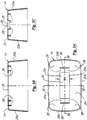
- the receptacle 12 comprising a top section 52 and bottom closure 56, along with the cover 14 and packages of syringes 11 (e.g., 100) can be nested together and shipped and sold in a suitable box 17 as seen in FIG. 2A. These are removed from the box 17 and the collector 10 assembled.
- the collector 10 is assembled by snapping the bottom closure 56 and top section 52 together to form the receptacle 12. This is usually accomplished by laying the top section 52 upside down on a table and snapping the bottom closure 56 firmly on the section 52. Then, the cover 14 is snapped onto the disposable receptacle 12 as shown in FIG. 2B and locked together in a manner which will be further explained later.
- the sharps collector 10 is used by placing a syringe 15 into a slot 36a which is exposed on the top of the collector 10 as shown in FIG. 1.
- a double shuttle 16 is then shifted from a first position as seen in FIG. 1 to a second position which causes the syringe 15 to be pushed to an aperture 40a (shown in FIG. 2B) in the top of the disposable receptacle 12.
- the syringe then falls through the aperture 40a, down a chute which will be described in detail later, and finally rests within the receptacle 12.
- the chute design is shown in FIGS. 7A-7G. Shifting or sliding the shuttle from the first position as seen in FIG. 1 to a second position exposes or opens a second like slot at the other side in the top of the collector 10.
- the double shuttle 16 remains in its second position until another syringe is ready for disposal. At that time, the syringe is placed in the now open second slot (36b) in the top of the collector 10. The double shuttle 16 is then moved back into its first position which causes the second syringe to be pushed to a second aperture 40b (FIG. 2B) in the top of the disposable receptacle 12. This second syringe then falls through the second aperture 40b, down a second chute, and finally rests within of the disposable receptacle 12. This action also causes the first slot 36a to be again exposed in the top of the collector to receive the next syringe.
- the design of the double shuttle 16 permits the sharps collector 10 to remain in a ready-to-use state because either slot 36a or slot 36b can always be exposed and ready to use.
- the design of the double shuttle 16 encourages the user to alternate between the two slots 36a and 36b for each use. By alternating between the slots 36a and 36b used, and therefore, the apertures 40a and 40b and associated chutes used, the syringes become distributed in the disposable receptacle 12 more evenly.
- the disposable receptacle 12 can be detached from the reusable cover 14 by pushing down on release tabs 32 (shown in FIGS. 1 and 2B). Then aperture covers 68a and 68b (shown in FIGS. 2B and 6) may be snapped closed over the respective apertures 40a and 40b thereby making the receptacle 12 tamper resistant. The receptacle 12 may then be discarded and the cover 14 may be reused to cover another receptacle 12.
- FIGS. 3A-3C show the reusable cover 14 in detail.
- the reusable cover 14 includes two end walls 20a and 20b, two side walls 22a and 22b, and a top wall 24.
- the end walls 20a and 20b, and the side walls 22a and 22b all taper inwardly toward the top wall 24 (note FIGS. 3B and 3C) so covers can be stacked and nested for ease of shipment and storage.
- the top wall 24 includes an aperture 26 for the movement of the double shuttle 16, the dimensions of which are important and which will be described in detail later.
- the inside of top wall 24 also includes eight depending posts 28 for the permanent attachment of guides (which will be described in detail later), and two slots 30 for release tabs 32 (which will be described in detail later) which are used to enable the cover 14 to be readily detached from the disposable receptacle 12.
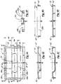
- the double shuttle design is shown in FIGS. 4A-4F.
- the guide design, including the release tabs, is shown in FIGS. 5A-5H.
- the double shuttle 16 includes a centrally disposed handle 34 to facilitate moving it back and forth in the aperture 26 in the cover 14.
- the double shuttle also includes two slots 36a and 36b (shown in FIGS. 4A and 4F) for receiving used syringes, and inner walls 38a and 38b (shown in FIGS. 4A, 4D, and 4F) which define the slots 36a and 36b and serve to push the used syringes to the respective apertures 40a and 40b (shown in FIGS. 2B and 6A) of the disposable receptacle 12.
- the double shuttle 16 also includes two elongated flanges 42. The flanges 42 enable the double shuttle 16 to be held onto the reusable cover 14 via the guides (described in detail below) while still allowing the shuttle 16 to move along the guides via the flanges 42.
- FIGS. 5A-5H show one of a pair of guides 18.
- Two guides 18 are used, one to engage each side of the double shuttle 16 and to attach the double shuttle 16 to the reusable cover 14.
- the guides 18 engage the flanges 42 of the double shuttle 16 to allow the shuttle 16 to move back and forth with respect to the aperture 26 in the top wall 24 of the receptacle 14.
- the guides 18 are preferably made from injection molded Delrin plastic.
- each guide 18 includes a release tab 32 which fits into slots 30 (shown in FIGS. 3A and 3B) on the reusable cover 14. The tabs 32 are used to enable the cover 14 to be detached from the disposable receptacle 12. As shown in FIGS. 5A and 5D, each guide 18 also includes holes 44 which fit onto the posts 28 (shown in FIG. 3A) for permanently attaching the guides 18 to the reusable cover 14. Additionally, as shown in FIGS. 5A, 5B, and 5D-5F, each guide 18 has a ledge 46 which fits over a corresponding flange 42 (shown in FIGS. 4A-4E) on the double shuttle 16.
- Ledge 46 and flange 42 fit in such a way that the double shuttle 16 is permanently attached to the cover 14, yet the flanges 42 of the double shuttle 16 are allowed to freely slide along the ledges 46 of the guides 18, limited in the mount by the walls 38a and 38b of the upstanding handle 34 engaging the edges 26a and 26b of the aperture 26 in the top 24 of the section 14. See FIG. 3A.
- the dimensions of the aperture or opening 26 in the top 24 of the top section 14 of the disposable receptacle 12, along with certain dimensions of the double shuttle 16, are important in the design of the present sharps collector 10.
- the length "L" (note Fig. 4D) of slots 36a and 36b of the double shuttle 16 is determined by the largest syringe size to be used.
- the width W2 and W3 (note Fig. 4A) of these slots 36a and 36b is the same and is a function on the width of the largest syringe.
- the length L and width W2, W3 are a function of the "footprint" of the largest syringe to be deposited in the collector.
- the amount of travel of the shuttle 16 back and forth within the slot 26, as will be apparent, is a function of the width W1 of slot 26 (FIG 3A).
- the widths W2 and W3 of the respective slots 36a and 36b, along with the amount of travel of the shuttle determine the spacings of the apertures 40a, 40b and associated chutes 54 (shown below).
- the width W4 of the handle 34 is approximately the same as W2, W3.
- the drawings in the present application are substantially to scale.
- the length L of slots 36 equals 121,9 mm (4.8 inches)
- the width W1 of the slot 26 equals 45,7 mm (1.8 inches)
- the width W2, W3 of the slots 38a, 38b of the double shuttle 16 are each 21,1 mm (0.83 inch)
- the width W4 of the handle 34 is 24,1 mm (0.95 inch).
- the depth of the slots 36a and 36b is whatever depth is required to allow the syringe 15 to lie within the slot and slide under the cover 14 to an aperture 40, and in an exemplary embodiment is 10,2 mm (0.40 inch). If the slots 36a and 36b are too wide, then the edge of an aperture 40 and chute will be exposed through opening 26, and if the slots 36a, 36b are too narrow, the syringe will tend to bind within the slot 36.
- each guide 18 also includes downward extending hooks 48 which form part of the locking and release arrangement between the cover and receptacle.
- the hooks 48 fit into attachment slots 50 (described later) of the disposable receptacle 12 and hold and essentially lock the cover 14 onto the receptacle 12.
- the hooks 48 can be disengaged from the attachment slots 50 by pressing down on the release tabs 32.
- the cover 14 can be released from the receptacle 12 by pressing down on the tabs 32 which cause the lower ends of the tabs 32 to push down on the top surface of the receptacle 12 and, therefore, cause the hooks 48 to pull away and release from the attachment slots 50.
- the attachment slots 50 of the receptacle 12 are shown in FIG. 6A.
- FIGS. 6A-6L, 7A-7G, and 8A-8E show the components of the disposable receptacle 12.
- the receptacle 12 is the container which holds the syringes to be discarded and is disposed of along with any syringes it contains.
- the receptacle 12 is preferably made from injection molded polypropylene.
- the receptacle 12 includes a top section 52 (shown in FIGS. 6A-6L), a pair of like chutes (one of which is shown in FIGS. 7A-7G), and a bottom closure 56 (shown in FIGS. 8A-8E).
- the receptacle 12 is assembled by snapping the chutes into the top section and the top section onto the bottom closure.
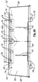
- FIGS. 6A-6L show a top section 52 of the disposable receptacle 12.
- the top section 52 of the receptacle 12 includes two end walls 58, a front wall 60, a back wall 62, and a top wall 64.
- the end walls 58, the front wall 60, and the back wall 62 all taper inwardly toward the top wall 64 to enable the receptacle 12 to be stacked and nested with like receptacles 12 compactly for ease of shipment and storage.
- the top wall 64 of the top section 52 as seen in FIG. 6A includes two apertures 40a and 40b for receiving syringes into the disposable receptacle 12.
- Two aperture covers 68a and 68b are used to seal off the apertures 40a and 40b when the disposable receptacle is filled and ready for disposal, and two finger indents 70a and 70b are provided to permit the aperture covers 68a and 68b to be easily flipped from their open position to their closed and locked position. Finger indent 70a also permits the handle 66 to be flipped open.
- each aperture cover 68 is attached to the disposable receptacle 12 by a living hinge 72.
- the living hinges 72 make it possible to easily pivot the aperture covers 68a and 68b from their open positions.
- the covers 68a and 68b are normally held in their open positions as seen in FIG. 2B because of the relationship of the covers 68, angled walls 71 (note FIGS. 6I and 6J) and ridges 73.
- FIG. 6I and 6J angled walls 71
- FIG. 9 see FIG. 9.
- the top wall 64 of the top section 52 also includes four attachment slots 50 (FIGS. 6A and 6H) used to affix the reusable cover 14 to the disposable receptacle 12. These attachment slots 50 receive the hooks 48 (shown in FIGS. 5B, 5C, and 5E-5H) of the guides 18 which fasten the cover 14 to the receptacle 12.
- a pull-out handle 66 may be attached to the front wall 60 which may be used to carry the receptacle 12 when the reusable cover 14 is removed.
- Lower ends 66a and 66b of the handle 66 are attached to the wall 60 and have living hinges 94 to allow the handle to pivot outwardly from the wall 60 as best seen in FIGS. 6A and 6E.
- the front wall 60 includes a pair of retainer ribs 92. The ribs 92 are provided to hold the pull-out handle 66 against the front wall 60.
- the underside of the top wall 64 of the top section 52 includes several ridges 74 as shown in FIGS. 6B-6F, and 6H-6J which create dams and help prevent liquid substances from leaking out of the receptacle 12 should the sharps collector 10 fall over or be turned over.
- the ridges 74 also include hooks 76 around the apertures 40 to attach the two chutes (one of which is shown in FIGS. 7A-7G) to the disposable receptacle 12 under the apertures 40.
- the bottom edge of the top section 52 includes four offset tabs 78, two extending from each wall 60 and 62, which allow the top section 52 to be snapped onto the bottom closure which will be described in detail below.
- the offset spacing of the tabs 78 is provided to prevent inadvertent assembly upside down of the top section 52 and the bottom closure.
- the bottom closure is shown in FIGS. 8A-8E and discussed in more detail later.
- FIGS. 7A-7G show details of each of the pair of chutes.
- One chute is disposed in each of the apertures 40a and 40b in the top of the disposable receptacle 12.
- Each chute 54 is positioned to receive syringes and allow them to fall into the receptacle 12.
- the chutes are preferably made from injection molded styrene and are designed to obstruct syringes which are contained in the receptacle 12 from protruding or reemerging from the receptacle 12. See also FIG. 9.
- Each chute as shown in FIG. 7A includes a top outer flange 108 which frames an opening 114, and has inner edges 120a and 120b and outer edges 122a and 122b.
- the opening 114 is defined by a depending arcuate wall 80 and a flat angled wall 82 which extend downward from the inner edges 120a and 120b respectively.
- the walls 80 and 82 have inner surfaces 110 and 112, respectively, which further define the opening 114 through which a deposited syringe must fall to enter the disposable receptacle 12.
- the depending arcuate wall 80 as shown in FIG. 7D extends perpendicular to and downward from the flange 108 at the inner edge 120a and then arcs inwardly towards the flat angled wall 82.
- the flat angled wall 82 extends downward from the flange 108 at the inner edge 120b and angles inward towards the arcuate wall 80.
- the walls 80 and 82 are formed integrally with the flange 108.
- the walls 80 and 82 are designed such that they define the opening 114 so the opening 114 can accommodate several different sizes of syringes as noted earlier, with or without needles, and prevent deposited syringes from exiting the disposable receptacle 12.
- the walls 80 and 82 of the chutes also have outer surfaces 116 and 118 respectively.
- the outer surfaces 116 and 118 include stiffening ribs 96, 98, and 100 which run along the outer surfaces 116 and 118 of the walls 80 and 82 and help maintain the rigidity and straightness of the opening 114 of each chute 54.
- each chute includes two integrally formed attachment ledges 84 and 86. These ledges 84 and 86 allow the chutes to be snapped onto the hooks 76 on the underside of the top wall 64 of the top section 52 (shown in FIGS. 6B, 6I, and 6J). Thus, by this ledge and hook arrangement each chute is attached to the disposable receptacle 12. Ribs or guards 102 are molded into the chute as seen in FIGS. 7A-7D.
- each chute The dimensions, angles, and slopes of each chute are important as an example which is workable for the preferred embodiment.
- the tolerance of the opening 114 of each chute can be tested by a cylinder and ball test.
- the opening 114 of each chute should be of a size that allows a cylinder of a particular size to pass through, but does not allow a ball of a particular, slightly larger size to pass through.
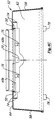
- FIGS. 8A-8E show a bottom closure 56 for the disposable receptacle 12.
- the bottom closure 56 includes a groove 88 all around its outer edge, along with attachment slots 90.
- the groove 88 is designed such that when the top section 52 and the bottom closure 56 are attached there is a good seal between them which is leak-resistant.
- the attachment slots 90 are designed to receive the tabs 78 on the bottom edge of the top section 52 (shown in FIGS. 6B-6E, and 6G) and provide a tamper-resistant connection.
- the slots 90 are spaced such that they will accept the tabs 78 only if the top section 52 and the bottom closure 56 are properly aligned (not upside down).
- the outer edge 89 adjacent the openings 90 be clear or translucent (or that the closure 56 be clear or translucent), and that the tabs 78 of the top section 52 be of a color (e.g., red) so that the tabs 78 will be visible through the edge 89. This provides a ready indicator to show whether or not the top section 52 and bottom closure 56 are properly attached together.
- a sharps collector has been shown and described herein for use with several sizes of insulin syringes as discussed earlier, it is to be understood that the collector design can be modified for other sizes and types of syringes, as well as for other sharps type devices.
- a receptacle 12 having a pair of apertures 40 has been shown as a preferred embodiment for distribution of syringes, a single aperture receptacle could be used along with a chute to reduce the chances of syringes reemerging. Even so, some form of shuttle arrangement, although not necessary, still may be desirable for ease of use.
- cover 14 and double shuttle arrangement 16 can be used on other forms of receptacles, even conventional forms of receptacles, for facilitating deposit of syringes and other sharps.
- the shuttle can be provided with a spring return.
- each of the chutes of said upper receptacle body is configured to form an opening defined by a flange which frames the opening and has inner edges which define the opening, and which has outer edges,
- each chute advantageously have inner and outer surfaces and ribs are formed integrally with said outer surfaces, said ribs extending along the outer surfaces to increase the rigidity thereof for maintaining the straightness of said opening in the chute.
- each chute may include integrally formed attachment ledges, said ledges providing a means for attaching the chutes to the upper receptacle body of the disposable receptacle.
- a number of said receptacle bodies may be stacked one inside another for storage.
- receptacle ridges are advantageously formed integrally with the inner surface of the top wall of said upper receptacle body, said ridges forming dams surrounding the apertures of said upper receptacle body to help prevent leaks of substances from inside the receptacle body through said apertures.
- the ridges may include hooks which allow for the attachment of the chutes onto the inner surface of the top wall of the upper receptacle body.
- the aperture covers are advantageously integrally formed with the outer surface of the top wall of the upper receptacle body, said aperture covers normally being retained open to expose said apertures but which for disposal of the receptacle fit over and cover the apertures of said upper receptacle body and help prevent syringes in the receptacle from re-emerging.
- Each of said covers may be connected to the upper receptacle body by a living hinge.
- the four side walls of said upper receptacle body may comprise two side walls, a back wall, and a front wall, with a pull-out handle integrally formed on the outer surface of said front wall, said handle providing a means for carrying said disposable receptacle.
- the handle may be connected to the front wall of the upper receptacle body by a living hinge.
- the receptacle is preferably made of injection molded polypropylene.
- the top wall of the upper receptacle body may have attachment slots, said slots providing a means for a cover to attach to and detach from said disposable receptacle.
- the receptacle may include a reusable decorative cover which may be attached to and detached from said disposable receptacle, and a pair of attachment guides attached to the reusable cover and have downward extending hooks for attaching the guides and, thus, the reusable cover to the disposable receptacle by engaging attachment slots formed in the disposable receptacle.
- the receptacle may have a reusable decorative cover which may be attached to and detached from said disposable receptacle, said reusable cover generally resembling an elongated box comprising four side walls and a top wall having inner and outer surfaces, said top wall having an elongated opening located therein, said opening permitting manipulation of a double shuttle, and
- the reusable cover preferably has a pair of attachment guides having holes which fit onto posts located on the inner surface of the top wall of the reusable cover and attach the guides to the reusable cover.
- the inner surface of the top wall of said cover advantageously has attachment posts, said posts providing a means for attaching the attachment guides to the reusable cover.
- the double shuttle preferably has a handle member between the parallel slots, said handle member extending slightly taller than the remainder of said double shuttle and protruding out of, but narrower than, the elongated opening in the reusable cover, said handle providing a means for moving said double shuttle back and forth in said opening and limiting such movement to the width of said elongated opening of the reusable cover.
- the double shuttle has two attachment flanges, said flanges providing a means for movably attaching said double shuttle to the reusable cover.
- one of either the upper receptacle body or the lower closure has a plurality of colored locking tabs and the other is formed to allow the tabs to be viewed to visibly indicate to the user whether or not the upper receptacle body and the lower closure are locked together.
- the upper receptacle body has a plurality of colored locking tabs and the lower closure is formed to allow the tabs to be viewed to visibly indicate to the user whether or not the upper receptacle body and the lower closure are locked together.
- the described apparatus may include a decorative cover adapted to fit over and cover the receptacle, the cover having an elongated opening through which syringes can pass to the shuttle, the shuttle underlying the cover and being adapted to move back and forth with respect to said opening to allow syringes to be distributed first to one elongated aperture and then to the other.
- the elongate apertures in the receptacle and the elongate opening in the shuttle are configured for receiving syringes therein in a horizontal orientation to allow syringes to be deposited in the shuttle horizontally and to drop horizontally through the apertures into the receptacle.
Landscapes
- Health & Medical Sciences (AREA)
- Surgery (AREA)
- Engineering & Computer Science (AREA)
- Life Sciences & Earth Sciences (AREA)
- Animal Behavior & Ethology (AREA)
- Veterinary Medicine (AREA)
- Biomedical Technology (AREA)
- Heart & Thoracic Surgery (AREA)
- Medical Informatics (AREA)
- Molecular Biology (AREA)
- Mechanical Engineering (AREA)
- General Health & Medical Sciences (AREA)
- Public Health (AREA)
- Nuclear Medicine, Radiotherapy & Molecular Imaging (AREA)
- Accommodation For Nursing Or Treatment Tables (AREA)
- Infusion, Injection, And Reservoir Apparatuses (AREA)
- Diaphragms For Electromechanical Transducers (AREA)
- Electrotherapy Devices (AREA)
- Measuring And Recording Apparatus For Diagnosis (AREA)
- Bipolar Transistors (AREA)
- Absorbent Articles And Supports Therefor (AREA)
Abstract
Description
- The present invention relates to collector devices, and more particularly to a "sharps" collector for devices such as syringes.
- The term "sharps" applies to any sharp device used in medical applications, such as hypodermic needles, lances, and the like. The dangers of disposing of these devices after use have become more prevalent with expanding diseases such as AIDS and hepatitis. Before disposal, the used devices must be contained such that exposure to others is minimized. These disposal problems are present in hospitals and doctor's offices, and are also present in home settings. Diabetics, for example, and others must dispose of numerous used needles and syringes. There are presently over two million diabetics in the United States, each of whom use an average of one and one-half syringes per day.
- In addition to the problem of providing a receptacle for receiving used syringes, the container itself must be disposable, hold a reasonable number of syringes, insure that the syringes are stacked or packed in some suitable way, be safe to use without a deposited syringe sticking out or reemerging from the receptacle, be secure so that a child or animal cannot reach in and injure themselves on the discarded syringes contained therein, be closeable for disposal, and be puncture resistant, leak resistant, break resistant, as well as be tamper resistant after being closed and tamper evident if opened. The use of non-toxic materials and incineratable materials is important because some receptacles are incinerated and/or disposed of at disposal sites. Also, for use in doctor's offices the receptacles may need to be autoclavable.
- US Patent Specification No 5,014,874 discloses a base having a disposable receptacle and a reusable cover resembling a box with an open bottom. The resuable cover has a shuttle which conceals access to the receptacle but which allows an item to be disposed of, to be transferred into the receptacle.
- The problem with this arrangement is that removal of the cover provides open access to the contents of the receptacle which is undesirable where used syringes are concerned. Furthermore, there is only a single access path to the receptacle from the cover.
- It is an object of the invention to provide an improved apparatus for holding and disposing of syringes.
- According to the present invention there is provided an apparatus for holding and disposing of syringes, comprising a disposable receptacle, a reusable cover generally resembling a box with an open bottom, said cover being configured to fit over, attach to, and cover said disposable receptacle and be detachable therefrom and a shuttle attached to the reusable cover to be located in an opening therein, said shuttle providing means by which syringes are discarded into the disposable receptacle when said cover is in place on the receptacle, said receptacle being characterised by an upper receptacle body generally resembling an elongate box having a plurality of substantially parallel elongate apertures therein, each of said apertures providing access to a respective chute mounted to the upper receptacle body and extending into the disposable receptacle, said apertures and chutes being adapted to pass syringes, and a lower receptacle closure adapted to engage said upper receptacle body and attach thereto, the cover being arranged to conceal said apertures and said shuttle being selectively operable to feed a syringe to a selected one of said apertures.
- According to the present invention there is further provided a method of containing and storing used syringes for disposal wherein the syringes are received into a receptacle and distributed into the receptacle in a substantially even manner, the method comprising the steps of (a) dropping a syringe in a horizontal orientation into an opening in a movable shuttle, (b) moving the shuttle in a predetermined manner to cause the syringe to drop substantially horizontally through an aperture and chute into a receptacle, characterised by (c) repeating steps (a) and (b) with a second syringe to cause the second syringe to be passed substantially horizontally through a second aperture and chute both spaced from said first aperture and first chute into the receptacle, and (d) repeating the foregoing steps (a) - (c) for additional syringes.
- The receptacle is a box-like structure which as hereinafter described includes a pair of apertures which act as access ports and have specially designed chutes for permitting different sized syringes to fall into the receptacle and be prevented from reemerging. The receptacle also has a pair of aperture covers which provide locking doors and may be flipped over the respective apertures and chutes, and snapped securely closed to make the receptacle tamper resistant once it is full and ready for final disposal.
- The chute design allows different sizes of syringes, with or without attached needles, to reliably fall into the receptacle in an organized and reasonable manner. The design shown and described herein is for 0.3, 0.5 and 1.0 ml insulin syringes. The cover has a shuttle for directing syringes to the apertures and chutes. The chute and shuttle designs cause the syringes to align with the longitudinal axis of the chute and to fall evenly into the receptacle. Thus, the syringes can fall into the receptacle in a manner which ensures efficient use of space. This "stacking" scheme enables the syringes to be inserted in a horizontal orientation and fall horizontally ("horizontal drop") into the receptacle and ensures that the receptacle will hold a reasonable number of syringes while enabling a relatively low profile container to be provided. In addition, the chute design prevents any syringes from protruding out of the receptacle and from being easily reached and removed.
- The reusable cover is provided to fit over the disposable receptacle. However, the disposable receptacle can be used with or without the cover. The cover also has the shuttle, termed a double shuttle, which serves to push the used syringes toward a particular aperture and chute, and cause each syringe to descend into the receptacle. The cover and shuttle allow the syringes to be alternately discarded into the receptacle through one, and then the other, of the chutes. Using the chutes alternately helps ensure an even distribution and nesting of the syringes within the receptacle and, thus, the efficient use of space within the receptacle.
- The cover preferably is designed such that it can be snapped onto, and locked with, the underlying receptacle but be quickly and simply unlocked for reuse when the disposable receptacle is discarded. This locking arrangement renders the collector child resistant and tamper resistant. The cover and shuttle design provides the further benefit of completely concealing from view the aperture and chute features of the disposable receptacle. The chute design, along with the cover and shuttle designs, render beyond reach the syringes which are enclosed in the receptacle.
- Apparatus for holding and disposing of syringes will now be described, by way of example, with reference to the accompanying diagrammatic drawings, in which:
- FIG. 1 is a perspective view of a complete sharps collector of the present invention as it is used;
- FIG. 2A is a perspective view of the disposable receptacle of FIG. 2B as packaged syringes are removed therefrom in preparation for use.
- FIG. 2B is a perspective view of a disposable receptacle of FIG. 1 as a decorative cover of FIG. 1 is being attached.
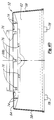
- FIG. 3A is a bottom view of a decorative cover of the collector.
- FIG. 3B is a cross-sectional view of the cover taken
along
line 3B-3B in FIG. 3A. - FIG. 3C is a cross-sectional view of the cover taken
along
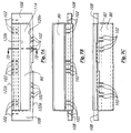
line 3C-3C in FIG. 3A. - FIG. 4A is a top view of a double shuttle for use with the cover of the present invention.
- FIG. 4B is a side view of the double shuttle.
- FIG. 4C is a cross-sectional view of the double
shuttle taken along
line 4C-4C in FIG. 4A. - FIG. 4D is a cross-sectional view of the double
shuttle taken along
line 4D-4D in FIG. 4A. - FIG. 4E is a cross-sectional view of the double
shuttle taken along
line 4E-4E in FIG. 4A. - FIG. 4F is a cross-sectional view of the double
shuttle taken along
line 4F-4F in FIG. 4A. - FIG. 5A is a top view of one of a pair of guides for the double shuttle of the present invention.
- FIG. 5B is a front view of the guide.
- FIG. 5C is a side view of the guide.
- FIG. 5D is a fragmentary view of the bottom side of the guide.
- FIG. 5E is a cross-sectional view of the guide taken
along
line 5E-5E in FIG. 5A. - FIG. 5F is a cross-sectional view of the guide taken
along
line 5F-5F in FIG. 5A. - FIG. 5G is a cross-sectional view of the guide taken
along
line 5G-5G in FIG. 5A. - FIG. 5H is a detailed enlargement of an attachment
hook of the guide taken from
circle 5H in FIG. 5G. - FIG. 6A is a top view of a top section of a disposable receptacle of the present invention.
- FIG. 6B is a front view of the top section.
- FIG. 6C is a cross-sectional view of the top section
taken along
line 6C-6C in FIG. 6A. - FIG. 6D is a cross-sectional view of the top section
taken along
line 6D-6D in FIG. 6A. - FIG. 6E is a cross-sectional view of the top section
with aperture covers in an open position taken along
line 6E-6E in FIG. 6A. - FIG. 6F is an enlarged partial bottom view of the top section.
- FIG. 6G is a detailed enlargement of a tab part of an
attachment mechanism of the disposable receptacle taken
from
circle 6G in FIG. 6E. - FIG. 6H is an enlarged cross-sectional view of an
attachment slot of the disposable receptacle taken along
line 6H-6H in FIG. 6A. - FIG. 6I is an enlarged cross-sectional view of an aperture and aperture cover of the disposable receptacle with the aperture cover in an open position taken along line 6I-6I in FIG. 6A.
- FIG. 6J is an enlarged view of an aperture cover in
an open position taken from
ellipse 6J in FIG. 6I. - FIG. 6K is an enlarged view of a rib used to hold a
handle of the disposable receptacle taken from
circle 6K in FIG. 6I. - FIG. 6L is a detailed enlargement of a living hinge
of an aperture cover taken from
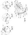
circle 6L in FIG. 6I. - FIG. 7A is a top or plan view of one of a pair of chutes used on the receptacle of the present invention.
- FIG. 7B is a first or front side view of the chute.
- FIG. 7C is a second or back side view of the chute.
- FIG. 7D is a cross-sectional view of the chute taken
along
line 7D-7D of FIG. 7A. - FIG. 7E is an enlarged view of a stiffener rib of the
chute taken from
circle 7E in FIG. 7D. - FIG. 7F is an enlarged view of a stiffener rib of the
chute taken from
circle 7F in FIG. 7D. - FIG. 7G is an enlarged view of an attachment ledge of
the chute taken from
circle 7G in FIG. 7D. - FIG. 7H-1 is an end view and FIG. 7H-2 is a side view of a sharp in the form of a hypodermic needle.
- FIG. 7I is a cross-sectional view of a chute.
- FIG. 7J is a cross-sectional view of a chute showing a path a hypodermic needle takes as it falls through the chute.
- FIG. 8A is a top view of a bottom closure of the disposable receptacle of the present invention.
- FIG. 8B is a side or elevational view of the bottom closure.
- FIG. 8C is a cross-sectional view of the bottom
closure taken along
line 8C-8C in FIG. 8A. - FIG. 8D is an enlarged cross-sectional view of a portion of the bottom closure taken from circle 8D in FIG. 8C.
- FIG. 8E is an enlarged cross-sectional view of a tab
receiving slot part of an attachment mechanism of the
bottom closure taken from
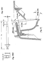
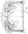
circle 8E in FIG. 8C. - FIG. 9 is a cross-sectional view of the assembled sharps collector illustrating how syringes fall through a chute and cannot readily come back out of a chute.
-
- Turning now to the drawings, and first to FIGS. 1 and 2, FIG. 1 shows a perspective view of the preferred embodiment of the present invention in the form of a
sharps collector 10 having a reusabledecorative cover 14. As shown in Fig. 2B, thesharps collector 10 includes an innerdisposable receptacle 12 which can be covered by the outerreusable cover 14. Thissharps collector 10, for receiving insulin syringes as noted earlier, is about the size of a facial tissue box. - The
receptacle 12 comprising atop section 52 andbottom closure 56, along with thecover 14 and packages of syringes 11 (e.g., 100) can be nested together and shipped and sold in asuitable box 17 as seen in FIG. 2A. These are removed from thebox 17 and thecollector 10 assembled. Thecollector 10 is assembled by snapping thebottom closure 56 andtop section 52 together to form thereceptacle 12. This is usually accomplished by laying thetop section 52 upside down on a table and snapping thebottom closure 56 firmly on thesection 52. Then, thecover 14 is snapped onto thedisposable receptacle 12 as shown in FIG. 2B and locked together in a manner which will be further explained later. - The
sharps collector 10 is used by placing asyringe 15 into aslot 36a which is exposed on the top of thecollector 10 as shown in FIG. 1. Adouble shuttle 16 is then shifted from a first position as seen in FIG. 1 to a second position which causes thesyringe 15 to be pushed to anaperture 40a (shown in FIG. 2B) in the top of thedisposable receptacle 12. The syringe then falls through theaperture 40a, down a chute which will be described in detail later, and finally rests within thereceptacle 12. The chute design is shown in FIGS. 7A-7G. Shifting or sliding the shuttle from the first position as seen in FIG. 1 to a second position exposes or opens a second like slot at the other side in the top of thecollector 10. - The
double shuttle 16 remains in its second position until another syringe is ready for disposal. At that time, the syringe is placed in the now open second slot (36b) in the top of thecollector 10. Thedouble shuttle 16 is then moved back into its first position which causes the second syringe to be pushed to asecond aperture 40b (FIG. 2B) in the top of thedisposable receptacle 12. This second syringe then falls through thesecond aperture 40b, down a second chute, and finally rests within of thedisposable receptacle 12. This action also causes thefirst slot 36a to be again exposed in the top of the collector to receive the next syringe. - The design of the
double shuttle 16 permits thesharps collector 10 to remain in a ready-to-use state because eitherslot 36a orslot 36b can always be exposed and ready to use. In addition, the design of thedouble shuttle 16 encourages the user to alternate between the twoslots slots apertures disposable receptacle 12 more evenly. - Once the
disposable receptacle 12 is full, it can be detached from thereusable cover 14 by pushing down on release tabs 32 (shown in FIGS. 1 and 2B). Then aperture covers 68a and 68b (shown in FIGS. 2B and 6) may be snapped closed over therespective apertures receptacle 12 tamper resistant. Thereceptacle 12 may then be discarded and thecover 14 may be reused to cover anotherreceptacle 12. - Each of the components of the collector will now be described in detail starting with the decorative cover and its associated double shuttle and its guides, and cover release mechanism.
- FIGS. 3A-3C show the
reusable cover 14 in detail. As shown in FIGS. 3A-3C, thereusable cover 14 includes twoend walls side walls top wall 24. Theend walls side walls - As shown in FIG. 3A, the
top wall 24 includes anaperture 26 for the movement of thedouble shuttle 16, the dimensions of which are important and which will be described in detail later. The inside oftop wall 24 also includes eight dependingposts 28 for the permanent attachment of guides (which will be described in detail later), and twoslots 30 for release tabs 32 (which will be described in detail later) which are used to enable thecover 14 to be readily detached from thedisposable receptacle 12. The double shuttle design is shown in FIGS. 4A-4F. The guide design, including the release tabs, is shown in FIGS. 5A-5H. - As shown in FIGS. 4A, 4C, and 4F, the
double shuttle 16 includes a centrally disposed handle 34 to facilitate moving it back and forth in theaperture 26 in thecover 14. The double shuttle also includes twoslots inner walls slots respective apertures disposable receptacle 12. As shown in FIGS. 4A-4E, thedouble shuttle 16 also includes twoelongated flanges 42. Theflanges 42 enable thedouble shuttle 16 to be held onto thereusable cover 14 via the guides (described in detail below) while still allowing theshuttle 16 to move along the guides via theflanges 42. - FIGS. 5A-5H show one of a pair of
guides 18. Two guides 18 are used, one to engage each side of thedouble shuttle 16 and to attach thedouble shuttle 16 to thereusable cover 14. Theguides 18 engage theflanges 42 of thedouble shuttle 16 to allow theshuttle 16 to move back and forth with respect to theaperture 26 in thetop wall 24 of thereceptacle 14. Theguides 18 are preferably made from injection molded Delrin plastic. - As shown in FIGS. 5A-5C, each
guide 18 includes arelease tab 32 which fits into slots 30 (shown in FIGS. 3A and 3B) on thereusable cover 14. Thetabs 32 are used to enable thecover 14 to be detached from thedisposable receptacle 12. As shown in FIGS. 5A and 5D, each guide 18 also includesholes 44 which fit onto the posts 28 (shown in FIG. 3A) for permanently attaching theguides 18 to thereusable cover 14. Additionally, as shown in FIGS. 5A, 5B, and 5D-5F, eachguide 18 has aledge 46 which fits over a corresponding flange 42 (shown in FIGS. 4A-4E) on thedouble shuttle 16.Ledge 46 andflange 42 fit in such a way that thedouble shuttle 16 is permanently attached to thecover 14, yet theflanges 42 of thedouble shuttle 16 are allowed to freely slide along theledges 46 of theguides 18, limited in the mount by thewalls upstanding handle 34 engaging theedges 26a and 26b of theaperture 26 in the top 24 of thesection 14. See FIG. 3A. - As noted earlier the dimensions of the aperture or
opening 26 in the top 24 of thetop section 14 of thedisposable receptacle 12, along with certain dimensions of thedouble shuttle 16, are important in the design of thepresent sharps collector 10. The length "L" (note Fig. 4D) ofslots double shuttle 16 is determined by the largest syringe size to be used. The width W2 and W3 (note Fig. 4A) of theseslots shuttle 16 back and forth within theslot 26, as will be apparent, is a function of the width W1 of slot 26 (FIG 3A). The widths W2 and W3 of therespective slots apertures handle 34 is approximately the same as W2, W3. - The drawings in the present application are substantially to scale. In an exemplary embodiment for use with insulin syringes of 0.3, 0.5 and 1.0 ml., the foregoing dimensions are, the length L of slots 36 equals 121,9 mm (4.8 inches), the width W1 of the
slot 26 equals 45,7 mm (1.8 inches), the width W2, W3 of theslots double shuttle 16 are each 21,1 mm (0.83 inch) the width W4 of thehandle 34 is 24,1 mm (0.95 inch). The depth of theslots syringe 15 to lie within the slot and slide under thecover 14 to anaperture 40, and in an exemplary embodiment is 10,2 mm (0.40 inch). If theslots aperture 40 and chute will be exposed throughopening 26, and if theslots - As shown in FIGS. 5B, 5C, and 5E-5H, each guide 18 also includes downward extending
hooks 48 which form part of the locking and release arrangement between the cover and receptacle. Thehooks 48 fit into attachment slots 50 (described later) of thedisposable receptacle 12 and hold and essentially lock thecover 14 onto thereceptacle 12. Thehooks 48 can be disengaged from theattachment slots 50 by pressing down on therelease tabs 32. Thus, thecover 14 can be released from thereceptacle 12 by pressing down on thetabs 32 which cause the lower ends of thetabs 32 to push down on the top surface of thereceptacle 12 and, therefore, cause thehooks 48 to pull away and release from theattachment slots 50. Theattachment slots 50 of thereceptacle 12 are shown in FIG. 6A. - FIGS. 6A-6L, 7A-7G, and 8A-8E show the components of the
disposable receptacle 12. As discussed earlier, thereceptacle 12 is the container which holds the syringes to be discarded and is disposed of along with any syringes it contains. Thereceptacle 12 is preferably made from injection molded polypropylene. Thereceptacle 12 includes a top section 52 (shown in FIGS. 6A-6L), a pair of like chutes (one of which is shown in FIGS. 7A-7G), and a bottom closure 56 (shown in FIGS. 8A-8E). Thereceptacle 12 is assembled by snapping the chutes into the top section and the top section onto the bottom closure. - FIGS. 6A-6L show a
top section 52 of thedisposable receptacle 12. As shown in FIGS. 6A-6E thetop section 52 of thereceptacle 12 includes twoend walls 58, afront wall 60, aback wall 62, and atop wall 64. Theend walls 58, thefront wall 60, and theback wall 62 all taper inwardly toward thetop wall 64 to enable thereceptacle 12 to be stacked and nested withlike receptacles 12 compactly for ease of shipment and storage. - The
top wall 64 of thetop section 52 as seen in FIG. 6A includes twoapertures disposable receptacle 12. Two aperture covers 68a and 68b are used to seal off theapertures finger indents Finger indent 70a also permits thehandle 66 to be flipped open. As shown in FIGS. 6E, 6I, 6J, and 6L, each aperture cover 68 is attached to thedisposable receptacle 12 by a livinghinge 72. The living hinges 72 make it possible to easily pivot the aperture covers 68a and 68b from their open positions. Thecovers aperture cover 68a is rotated fully counterclockwise as seen in FIG. 6I and 6J it is held in the fully open position substantially against thewall 71a by the outer end of thecover 68a engaging the inner surface of theridge 73a. Also see FIG. 9. - The
top wall 64 of thetop section 52 also includes four attachment slots 50 (FIGS. 6A and 6H) used to affix thereusable cover 14 to thedisposable receptacle 12. Theseattachment slots 50 receive the hooks 48 (shown in FIGS. 5B, 5C, and 5E-5H) of theguides 18 which fasten thecover 14 to thereceptacle 12. - As shown in FIGS. 6A, 6E, and 6F, a pull-
out handle 66 may be attached to thefront wall 60 which may be used to carry thereceptacle 12 when thereusable cover 14 is removed. Lower ends 66a and 66b of thehandle 66 are attached to thewall 60 and have living hinges 94 to allow the handle to pivot outwardly from thewall 60 as best seen in FIGS. 6A and 6E. As shown in FIGS. 6B, 6E, 6I and 6K, thefront wall 60 includes a pair ofretainer ribs 92. Theribs 92 are provided to hold the pull-out handle 66 against thefront wall 60. - The underside of the
top wall 64 of thetop section 52 includesseveral ridges 74 as shown in FIGS. 6B-6F, and 6H-6J which create dams and help prevent liquid substances from leaking out of thereceptacle 12 should thesharps collector 10 fall over or be turned over. Theridges 74 also includehooks 76 around theapertures 40 to attach the two chutes (one of which is shown in FIGS. 7A-7G) to thedisposable receptacle 12 under theapertures 40. - As shown in FIGS. 6B-6E, and 6G, the bottom edge of the
top section 52 includes four offsettabs 78, two extending from eachwall top section 52 to be snapped onto the bottom closure which will be described in detail below. The offset spacing of thetabs 78 is provided to prevent inadvertent assembly upside down of thetop section 52 and the bottom closure. The bottom closure is shown in FIGS. 8A-8E and discussed in more detail later. - FIGS. 7A-7G show details of each of the pair of chutes. One chute is disposed in each of the
apertures disposable receptacle 12. Each chute 54 is positioned to receive syringes and allow them to fall into thereceptacle 12. The chutes are preferably made from injection molded styrene and are designed to obstruct syringes which are contained in thereceptacle 12 from protruding or reemerging from thereceptacle 12. See also FIG. 9. - Each chute as shown in FIG. 7A includes a top
outer flange 108 which frames anopening 114, and hasinner edges outer edges opening 114 is defined by a dependingarcuate wall 80 and a flatangled wall 82 which extend downward from theinner edges walls inner surfaces opening 114 through which a deposited syringe must fall to enter thedisposable receptacle 12. - The design of the chute opening (which includes parts of the "inner box" and the "chute") for a particular syringe with dimensions and shape similar to FIG. 7H is dictated by the following rules.
- 1. The width of the line-of-sight gap (FIG. 7I) to be less than 1/2 of the syringe body diameter (i.e., 50Ds max.).
- 2. The depth of the line-of-sight gap (FIG. 7I) from where the syringe body hits the chute to the outside surface to be greater the needle length (i.e., Ln min.).
- 3. The minimum width of the chute (FIG. 7I) at all points to be greater than 1.1 times the maximum width of the syringe (i.e., 1.1X min.).
- 4. No surface (FIG. 7I) to be less than 20 degrees from the horizontal.
- 5. The minimum envelope of the chute (FIG. 7J) to be a locus of points that allow the maximum syringe profile to pass through without violating rules 1 - 4.
- 6. Additional space may be allowed for manufacturing, assembly, etc., that do not violate rules 1 - 5.
-
- The depending
arcuate wall 80 as shown in FIG. 7D extends perpendicular to and downward from theflange 108 at theinner edge 120a and then arcs inwardly towards the flatangled wall 82. The flatangled wall 82 extends downward from theflange 108 at theinner edge 120b and angles inward towards thearcuate wall 80. Thewalls flange 108. Thewalls opening 114 so theopening 114 can accommodate several different sizes of syringes as noted earlier, with or without needles, and prevent deposited syringes from exiting thedisposable receptacle 12. - As shown in FIGS. 7D-7F the
walls outer surfaces outer surfaces ribs outer surfaces walls opening 114 of each chute 54. - The
outer edges flange 108 of each chute include two integrally formedattachment ledges ledges hooks 76 on the underside of thetop wall 64 of the top section 52 (shown in FIGS. 6B, 6I, and 6J). Thus, by this ledge and hook arrangement each chute is attached to thedisposable receptacle 12. Ribs orguards 102 are molded into the chute as seen in FIGS. 7A-7D. These are provided to prevent a needle of a syringe which is in the receptacle from sticking out of the openings or cracks between the edges of the chute and body of thetop section 52 of thereceptacle 12 where the chute attaches at theaperture 40. - The dimensions, angles, and slopes of each chute are important as an example which is workable for the preferred embodiment. The tolerance of the
opening 114 of each chute can be tested by a cylinder and ball test. Theopening 114 of each chute should be of a size that allows a cylinder of a particular size to pass through, but does not allow a ball of a particular, slightly larger size to pass through. - FIGS. 8A-8E show a
bottom closure 56 for thedisposable receptacle 12. As shown in FIGS. 8A-8E, thebottom closure 56 includes agroove 88 all around its outer edge, along withattachment slots 90. Thegroove 88 is designed such that when thetop section 52 and thebottom closure 56 are attached there is a good seal between them which is leak-resistant. Theattachment slots 90 are designed to receive thetabs 78 on the bottom edge of the top section 52 (shown in FIGS. 6B-6E, and 6G) and provide a tamper-resistant connection. Theslots 90 are spaced such that they will accept thetabs 78 only if thetop section 52 and thebottom closure 56 are properly aligned (not upside down). It is preferable that theouter edge 89 adjacent theopenings 90 be clear or translucent (or that theclosure 56 be clear or translucent), and that thetabs 78 of thetop section 52 be of a color (e.g., red) so that thetabs 78 will be visible through theedge 89. This provides a ready indicator to show whether or not thetop section 52 andbottom closure 56 are properly attached together. - Although a particular and preferred embodiment of a sharps collector has been shown and described herein for use with several sizes of insulin syringes as discussed earlier, it is to be understood that the collector design can be modified for other sizes and types of syringes, as well as for other sharps type devices. Although a
receptacle 12 having a pair ofapertures 40 has been shown as a preferred embodiment for distribution of syringes, a single aperture receptacle could be used along with a chute to reduce the chances of syringes reemerging. Even so, some form of shuttle arrangement, although not necessary, still may be desirable for ease of use. Furthermore, thecover 14 anddouble shuttle arrangement 16 can be used on other forms of receptacles, even conventional forms of receptacles, for facilitating deposit of syringes and other sharps. Also, particularly in the case of a single aperture receptacle, the shuttle can be provided with a spring return. - While an embodiment of the present invention has been shown and described, various modifications may be made without departing from the scope of the present invention, as defined in the claims
- Preferably each of the chutes of said upper receptacle body is configured to form an opening defined by a flange which frames the opening and has inner edges which define the opening, and which has outer edges,
- a depending arcuate wall which initially extends perpendicular to and downward from the flange at the inner edge of the flange, and then arcs inward towards a flat angled wall, and
- a flat angled wall which extends downward from the flange at the inner edge of the flange and angles inward towards the arcuate wall, and
- said chutes are mounted directly below and in alignment with the apertures of the top wall of the upper receptacle body, said chutes providing a means through which syringes fall as syringes are dropped through the apertures and become enclosed in and obstructed from protruding or re-emerging from said disposable receptacle.
-
- In the receptacle described the depending arcuate wall and the flat angled wall of each chute advantageously have inner and outer surfaces and ribs are formed integrally with said outer surfaces, said ribs extending along the outer surfaces to increase the rigidity thereof for maintaining the straightness of said opening in the chute.
- As will be appreciated the outer edges of the flange of each chute may include integrally formed attachment ledges, said ledges providing a means for attaching the chutes to the upper receptacle body of the disposable receptacle.
- Because the side walls of said upper receptacle body are tapered inward towards the top, a number of said receptacle bodies may be stacked one inside another for storage.
- In the receptacle ridges are advantageously formed integrally with the inner surface of the top wall of said upper receptacle body, said ridges forming dams surrounding the apertures of said upper receptacle body to help prevent leaks of substances from inside the receptacle body through said apertures.
- The ridges may include hooks which allow for the attachment of the chutes onto the inner surface of the top wall of the upper receptacle body.
- The aperture covers are advantageously integrally formed with the outer surface of the top wall of the upper receptacle body, said aperture covers normally being retained open to expose said apertures but which for disposal of the receptacle fit over and cover the apertures of said upper receptacle body and help prevent syringes in the receptacle from re-emerging.
- Each of said covers may be connected to the upper receptacle body by a living hinge.
- The four side walls of said upper receptacle body may comprise two side walls, a back wall, and a front wall, with a pull-out handle integrally formed on the outer surface of said front wall, said handle providing a means for carrying said disposable receptacle.
- The handle may be connected to the front wall of the upper receptacle body by a living hinge.
- The receptacle is preferably made of injection molded polypropylene.
- The top wall of the upper receptacle body may have attachment slots, said slots providing a means for a cover to attach to and detach from said disposable receptacle.
- The receptacle may include a reusable decorative cover which may be attached to and detached from said disposable receptacle, and a pair of attachment guides attached to the reusable cover and have downward extending hooks for attaching the guides and, thus, the reusable cover to the disposable receptacle by engaging attachment slots formed in the disposable receptacle.
- Instead the receptacle may have a reusable decorative cover which may be attached to and detached from said disposable receptacle, said reusable cover generally resembling an elongated box comprising four side walls and a top wall having inner and outer surfaces, said top wall having an elongated opening located therein, said opening permitting manipulation of a double shuttle, and
- a generally rectangular double shuttle movably attached to the inner surface of the top wall of said reusable cover, and said double shuttle having walls defining parallel elongated slots for receiving syringes, said walls providing a means for pushing syringes toward the apertures of said disposable receptacle.
-
- The reusable cover preferably has a pair of attachment guides having holes which fit onto posts located on the inner surface of the top wall of the reusable cover and attach the guides to the reusable cover.
- The inner surface of the top wall of said cover advantageously has attachment posts, said posts providing a means for attaching the attachment guides to the reusable cover.
- The double shuttle preferably has a handle member between the parallel slots, said handle member extending slightly taller than the remainder of said double shuttle and protruding out of, but narrower than, the elongated opening in the reusable cover, said handle providing a means for moving said double shuttle back and forth in said opening and limiting such movement to the width of said elongated opening of the reusable cover.
- Instead the double shuttle has two attachment flanges, said flanges providing a means for movably attaching said double shuttle to the reusable cover.
- Preferably one of either the upper receptacle body or the lower closure has a plurality of colored locking tabs and the other is formed to allow the tabs to be viewed to visibly indicate to the user whether or not the upper receptacle body and the lower closure are locked together.
- Alternately the upper receptacle body has a plurality of colored locking tabs and the lower closure is formed to allow the tabs to be viewed to visibly indicate to the user whether or not the upper receptacle body and the lower closure are locked together.
- The described apparatus may include a decorative cover adapted to fit over and cover the receptacle, the cover having an elongated opening through which syringes can pass to the shuttle, the shuttle underlying the cover and being adapted to move back and forth with respect to said opening to allow syringes to be distributed first to one elongated aperture and then to the other.
- Preferably the elongate apertures in the receptacle and the elongate opening in the shuttle are configured for receiving syringes therein in a horizontal orientation to allow syringes to be deposited in the shuttle horizontally and to drop horizontally through the apertures into the receptacle.
Claims (29)
- An apparatus for holding and disposing of syringes, comprising a disposable receptacle (12), a reusable cover (14) generally resembling a box with an open bottom, said cover (14) being configured to fit over, attach to, and cover said disposable receptacle (12) and be detachable therefrom and a shuttle (16) attached to the reusable cover (14) to be located in an opening (26) therein, said shuttle (16) providing means by which syringes are discarded into the disposable receptacle (12) when said cover (14) is in place on the receptacle, said receptacle being characterised by an upper receptacle body (52) generally resembling an elongate box having a plurality of substantially parallel elongate apertures (40a,40b) therein, each of said apertures (40a,40b) providing access to a respective chute mounted to the upper receptacle body (52) and extending into the disposable receptacle (12), said apertures (40a,40b) and chutes being adapted to pass syringes, and a lower receptacle closure (56) adapted to engage said upper receptacle body (52) and attach thereto, the cover (14) being arranged to conceal said apertures (40a,40b) and said shuttle (15) being selectively operable to feed a syringe to a selected one of said apertures (40a,40b).
- Apparatus according to Claim 1, characterised in that the lower receptacle closure (56) and the upper receptacle body (52) form a leak resistant seal therebetween.
- Apparatus according to Claim 1 or to Claim 2, characterised in that said disposable receptacle has two parallel elongate apertures (40a,40b) providing access to respective ones of a pair of chutes, the pair of chutes being configured to guide and introduce syringes into said disposable receptacle (12) and to obstruct contained syringes from protruding or re-emerging from said disposable receptacle (12), and in that the shuttle (16) comprises a double shuttle attached to the reusable cover (14), said double shuttle (16) providing means by which syringes are discarded into the disposable receptacle, through the apertures (40a,40b) and chutes of said disposable receptacle (12) when said cover (14) is in place on the receptacle (12).
- Apparatus according to any one of Claims 1 to 3, characterised in that the upper receptacle body (52) has a top wall (64) with inner and outer surfaces, four side walls (58,60,62); and an open bottom, and fasteners (78) formed thereon, and in that the lower receptacle closure (56) has a groove (88) and fasteners (90) formed thereon which corresponds to and connect with the four side walls (58,60,62) and the fasteners (78) of said upper receptacle body (52) for thereby holding said lower receptacle closure (56) onto said upper receptacle body (52) and closing said open bottom of the upper receptacle body (52) to form said disposable receptacle (12).
- Apparatus according to Claim 4, characterised in that said disposable receptacle (12) has attachment slots (50), said slots (50) enable the cover (14) to attach to and detach from said disposable receptacle (12), in that said cover (14) has attachment posts enabling attaching of attachment guides (18) to the reusable cover, said cover (14) having openings providing a means for release tabs (32) to protrude through the cover (14), and a pair of attachment guides having holes which fit onto posts located on the reusable cover (14) and attach the guides to the reusable cover (14), downward extending hooks (48) for attaching the reusable cover (14) to the disposable receptacle by engaging attachment slots (50) formed in the disposable receptacle (12), upward extending release tabs (32) which fit through openings formed in the reusable cover (12) and, when pressed down, cause the reusable cover (14) to be release from the disposable receptacle by disengaging said attachment hooks (48) from said attachment slots (50), and attachment ledges for attaching the double shuttle (16) to the reusable cover (14) while allowing manipulation of said double shuttle (16).
- Apparatus according to any preceding claim, characterised in that each chute of said upper receptacle body (52) is configured to form an opening (114) defined by a flange (108) which frames the opening (114) and has inner edges which define the opening (114), and which has outer edges, a depending arcuate wall (80) which initially extends perpendicular to and downward from the flange (108) at the inner edge of the flange (108) and then arcs inward towards a flat angled wall, the flat angled wall (82) extending downwardly from the flange (108) at the inner edge of the flange (108) and angles inward towards the arcuate wall (80), and wherein said chutes are mounted directly below and in alignment with the apertures (40a,40b) of the upper receptacle body (52), said chutes providing a means through which syringes fall as syringes are dropped through the apertures (40a,40b) and become enclosed in and obstructed from protruding or re-emerging from said disposable receptacle (12).
- Apparatus according to Claim 5, characterised in that the depending arcuate wall (80) and the flat angled wall (82) of each chute have inner and outer surfaces (116,118) and ribs (96,98,100) are formed integrally with said outer surfaces (116,118) said ribs (96,98,100) extending along the outer surfaces to increase the rigidity thereof for maintaining the straightness of said openings (114) in the chute.
- Apparatus according to Claim 5, characterised in that the outer edges (122a,122b) of the flange (108) of each chute includes integrally formed attachment ledges (84,86), said ledges (84,86) providing a means for attaching the chutes to the upper receptacle body (52) of the disposable receptacle (12).
- Apparatus according to Claim 1, characterised in that the sides of said upper receptacle body (52) are tapered inward towards a top so that a number of said receptacle bodies (52) may be stacked one inside another for storage.
- Apparatus according to Claim 1, characterised in that ridges (74) are formed integrally with inner surfaces of said upper receptacle body (52), said ridges (74) form dams surrounding the apertures of said upper receptacle body and help prevent leaks of substances from inside the receptacle body (52) through said apertures.
- Apparatus according to Claim 1, characterised in that said ridges (74) include hooks (76) which allow for the attachment of the chutes onto the inner surface of the upper receptacle body (52).
- Apparatus according to Claim 1, characterised by aperture covers (68a,68b) are integrally formed with an outer surface of the upper receptacle body (52), said aperture covers (68a,68b) normally being retained open to expose said apertures (40a,40b) and which for disposal of the receptacle fit over and cover the apertures of said upper receptacle body (52) and help prevent syringes in the receptacle from reemerging.
- Apparatus according to Claim 11, characterised in that each of said covers (68a,68b) is connected to the upper receptacle body by a living hinge (72).
- Apparatus according to Claim 1, characterised in that the upper receptacle body (52) comprises a pull-out handle (66) integrally formed thereon, said handle (66) providing a means for carrying said disposable receptacle (12).
- Apparatus according to Claim 14, characterised in that said handle (66) is connected to the upper receptacle body (54) by a living hinge (94).
- Apparatus according to any preceding claim, characterised in that said receptacle (12) is made of injection molded polypropylene.
- Apparatus according to Claim 1, characterised in that the upper receptacle body (52) has attachment slots, said slots enabling a cover (14) to attach to and detach from said disposable receptacle (12), and further comprising a reusable decorative cover (14) which may be attached to and detached from said disposable receptacle (12), and a pair of attachment guides attached to the reusable cover (14) and have downward extending hooks for attaching the guides and, thus, the reusable cover (14) to the disposable receptacle by engaging attachment slots formed in the disposable receptacle (12).
- Apparatus according to Claim 1, characterised by a reusable decorative cover (14) which may be attached to and detached from said disposable receptacle (12), said reusable cover (14) generally resembling an elongate box comprising four side walls (20a,20b,22a,22b) and a top wall (24) having inner and outer surfaces, said top wall (24) having an elongate opening (26) located therein, said opening (26) permitting manipulation of a double shuttle (16), the shuttle (16) being movably attached to the inner surface of the top wall (24) of said reusable cover (14), and said double shuttle (16) having walls defining parallel elongate slots (36a,36b) for receiving syringes, said walls providing a means for pushing syringes toward the apertures (40a,40b) of said disposable receptacle (12).
- Apparatus according to Claim 17, characterised in that the reusable cover (14) has a pair of attachment guides (18) having holes (44) which fit onto posts (28) located on the inner surface of the reusable cover and attach the guides to the reusable cover, downward extending hooks (48) for attaching the guides (18) and, thus, the reusable cover (14) to the disposable receptacle by engaging attachment slots (50) formed in the disposable receptacle, upward extending release tabs (32) which fit through slots (30) formed in the reusable cover (14) and which, when pressed down, cause the reusable cover (14) to be released from the disposable receptacle (12) by disengaging said attachment hooks from said attachment slots, and attachment ledges for attaching the double shuttle (16) to the reusable cover (14) while allowing sliding movement of said double shuttle (16).
- Apparatus according to Claim 18, characterised in that the top wall of said cover has attachment posts (28), said posts (28) enabling attaching the attachment guides to the reusable cover (14).
- Apparatus according to Claim 17, characterised in that the double shuttle (16) has a handle member (34) between the parallel slots (36a,36b), said handle member (34) extending slightly taller than the remainder of said double shuttle (16) and protruding out of, but narrower than, the elongate opening (26) in the reusable cover (14), said handle (34) providing a means for moving said double shuttle (16) back and forth in said opening and limiting such movement to the width of said elongate opening of the reusable cover (14).
- Apparatus according to Claim 18, characterised in that the double shuttle (16) has two attachment flanges (43), said flanges (42) enabling movably attaching said double shuttle (16) to the reusable cover (14).
- Apparatus according to Claim 1, characterised in that one of either the upper receptacle body (52) or the lower closure (56) has a plurality of coloured locking tabs and the other is formed to allow the tabs to be viewed to visibly indicate whether or not the upper receptacle body (52) and the lower closure (56) are locked together.
- Apparatus according to Claim 1, characterised in that the upper receptacle body (52) has a plurality of coloured locking tabs (78) and the lower closure (56) is formed to allow the tabs (78) to be viewed to visibly indicate whether or not the upper receptacle body (52) and the lower closure (56) are locked together.
- Apparatus according to Claim 1, characterised in that each chute defines an opening (114) having inner and outer edges, a depending arcuate wall (80) which initially extends perpendicular to and downward from the chute at the inner edge of the opening (114), and then arcs inward towards a flat angled wall (82), the flat angled wall (82) extending downward from the chute at the inner edge of the opening (114) and angles inward towards the arcuate wall (80), and said chutes enabling syringes to fall therethrough as syringes are dropped through the apertures and said chutes obstructing syringes from protruding or re-emerging from said disposable receptacle.
- Apparatus according to Claim 1, characterised by a shuttle assembly (16) having at least one elongate opening (36) for initially receiving each syringe and being movable with respect to the top of the receptacle body (52) for pushing a syringe substantially horizontally into respective apertures (40a,40b) of the receptacle body (52), and wherein the chutes are disposed with respect to the apertures (40a,40b) in the receptacle body (52) to allow syringes to fall through an aperture (40a,40b) into the receptacle body (52), and the chutes being configured to substantially prevent reemergence of a syringe from the receptacle body (52).
- Apparatus according to Claim 25, characterised by a decorative cover (14) adapted to fit over and cover the receptacle (12), the cover (14) having an elongate opening (36) through which syringes can pass to the shuttle (16), the shuttle (16) underlying the cover (14) and being adapted to move back and forth with respect to said opening to allow syringes to be distributed first to one elongate aperture (40a,40b) and then to another.
- Apparatus according to Claim 27, characterised in that the elongate apertures (40a,40b) in the receptacle (12) and the elongate opening (36) in the shuttle are configured for receiving syringes therein in a horizontal orientation to allow syringes to be deposited in the shuttle (16) horizontally and to drop horizontally through the apertures into the receptacle.
- A method of containing and storing used syringes for disposal wherein the syringes are received into a receptacle and distributed into the receptacle in a substantially even manner, the method comprising the steps of(a) dropping a syringe in a horizontal orientation into an opening in a movable shuttle,(b) moving the shuttle in a predetermined manner to cause the syringe to drop substantially horizontally through an aperture and chute into a receptacle, characterised by(c) repeating steps (a) and (b) with a second syringe to cause the second syringe to be passed substantially horizontally through a second aperture and chute both spaced from said first aperture and first chute into the receptacle, and(d) repeating the foregoing steps (a) - (c) for additional syringes.
Applications Claiming Priority (3)
| Application Number | Priority Date | Filing Date | Title |
|---|---|---|---|
| US07/789,739 US5184720A (en) | 1991-11-08 | 1991-11-08 | Sharps collector |
| US789739 | 1991-11-08 | ||
| PCT/US1992/009490 WO1993009039A1 (en) | 1991-11-08 | 1992-11-04 | Sharps collector |
Publications (3)
| Publication Number | Publication Date |
|---|---|
| EP0611358A1 EP0611358A1 (en) | 1994-08-24 |
| EP0611358A4 EP0611358A4 (en) | 1995-01-11 |
| EP0611358B1 true EP0611358B1 (en) | 1999-02-24 |
Family
ID=25148546
Family Applications (2)
| Application Number | Title | Priority Date | Filing Date |
|---|---|---|---|
| EP19920310073 Withdrawn EP0541339A3 (en) | 1991-11-08 | 1992-11-03 | Sharps collector |
| EP92925076A Expired - Lifetime EP0611358B1 (en) | 1991-11-08 | 1992-11-04 | Sharps collector |
Family Applications Before (1)
| Application Number | Title | Priority Date | Filing Date |
|---|---|---|---|
| EP19920310073 Withdrawn EP0541339A3 (en) | 1991-11-08 | 1992-11-03 | Sharps collector |
Country Status (11)
| Country | Link |
|---|---|
| US (1) | US5184720A (en) |
| EP (2) | EP0541339A3 (en) |
| JP (1) | JPH07500753A (en) |
| AT (1) | ATE176856T1 (en) |
| AU (1) | AU3126793A (en) |
| CA (1) | CA2122444A1 (en) |
| DE (1) | DE69228484T2 (en) |
| MX (1) | MX9206390A (en) |
| NO (1) | NO941657L (en) |
| WO (1) | WO1993009039A1 (en) |
| ZA (1) | ZA928464B (en) |
Cited By (2)
| Publication number | Priority date | Publication date | Assignee | Title |
|---|---|---|---|---|
| US10321968B2 (en) | 2015-10-23 | 2019-06-18 | Medline Industries, Inc. | Sharps container |
| GB2631250A (en) * | 2023-06-21 | 2025-01-01 | Pineapple Contracts Unlimited | Anti-ligature bin |
Families Citing this family (34)
| Publication number | Priority date | Publication date | Assignee | Title |
|---|---|---|---|---|
| WO1994024021A1 (en) * | 1993-04-12 | 1994-10-27 | Specialized Health Products, Inc. | Container for transport and disposal of medical instruments |
| US5570783A (en) * | 1994-03-07 | 1996-11-05 | Specialized Health Products, Inc. | Apparatus and methods for transporting and discarding medical materials |
| US5474180A (en) * | 1994-03-07 | 1995-12-12 | Specialized Health Products, Inc. | Container assembly for transport and disposal of medical materials |
| US5630506A (en) * | 1994-03-07 | 1997-05-20 | Specialized Health Products, Inc. | Apparatus and method for transporting and discarding medical materials |
| USD362502S (en) | 1994-03-23 | 1995-09-19 | Carol A. Jackson | Waste disposal unit |
| US6524230B1 (en) * | 1994-07-22 | 2003-02-25 | Ranpak Corp. | Packing material product and method and apparatus for making, monitoring and controlling the same |
| US5573132A (en) * | 1994-11-25 | 1996-11-12 | Kanfer; Joseph S. | Dispensing container |
| US5494158A (en) * | 1994-12-29 | 1996-02-27 | Mmct Holdings, Llc | Syringe sales and disposal box |
| US5848692A (en) * | 1997-06-18 | 1998-12-15 | Specialized Health Products, Inc. | Unimold container for discarding medical material |
| US6283909B1 (en) * | 1999-01-22 | 2001-09-04 | Fraser R. Sharp | Container for supplying medical products and disposal of medical waste material |
| USD431079S (en) * | 1999-02-17 | 2000-09-19 | Stik Stoppers Inc. | Medical needle container |
| US6876991B1 (en) | 1999-11-08 | 2005-04-05 | Collaborative Decision Platforms, Llc. | System, method and computer program product for a collaborative decision platform |
| US6591989B2 (en) * | 2000-02-10 | 2003-07-15 | Mcneill Allen R. | Display sleeve enclosure for a dispensing container |
| US7159714B2 (en) * | 2003-02-21 | 2007-01-09 | Becton, Dickinson And Company | Sharps transport and disposal system |
| US6811679B2 (en) | 2003-03-28 | 2004-11-02 | Council Of Scientific & Industrial Research | Process for electrochemical oxidation of bromide to bromine |
| US7562025B2 (en) * | 2003-09-19 | 2009-07-14 | Vesta Medical, Llc | Waste sorting system with query function, and method thereof |
| WO2005029286A2 (en) * | 2003-09-19 | 2005-03-31 | Vesta Medical, Llc | System and method for sorting medical waste for disposal |
| US7660724B2 (en) * | 2003-09-19 | 2010-02-09 | Vesta Medical, Llc | Waste sorting system utilizing removable liners |
| US7275645B2 (en) * | 2003-09-19 | 2007-10-02 | Vesta Medical, Llc | Handheld medical waste sorting device |
| US8195328B2 (en) * | 2003-09-19 | 2012-06-05 | Vesta Medical, Llc | Combination disposal and dispensing apparatus and method |
| US7311207B2 (en) * | 2003-09-19 | 2007-12-25 | Vesta Medical, Llc | System for sorting discarded and spent pharmaceutical items |
| US7318529B2 (en) * | 2003-09-19 | 2008-01-15 | Vest Medical, Llc | Method for sorting discarded and spent pharmaceutical items |
| US7303081B2 (en) * | 2003-09-19 | 2007-12-04 | Vesta Medical, Llc | Handheld medical waste sorting method |
| US7644834B2 (en) * | 2004-05-27 | 2010-01-12 | Navilyst Medical, Inc. | Splash minimizing lid for liquid waste receptacle |
| US20060219718A1 (en) | 2005-04-05 | 2006-10-05 | Sherwood Services, Ag | Integral tortuous path receptacle cover |
| US20080254170A1 (en) * | 2007-04-12 | 2008-10-16 | Neil Edward Darin | multi-compartment produce container with controlled gas permeation |
| US20090204078A1 (en) * | 2008-02-13 | 2009-08-13 | Boston Scientific Scimed, Inc. | Manifold and Valve Seal for Use with a Medical Device |
| US20090236347A1 (en) | 2008-03-19 | 2009-09-24 | Ultimed Inc. | Sharps container |
| US9144642B2 (en) * | 2009-09-18 | 2015-09-29 | Becton, Dickinson And Company | Shipping container integrating a sharps disposal container with a new product storage container |
| US8998031B2 (en) | 2011-08-26 | 2015-04-07 | Stericycle, Inc. | Waste container assembly |
| US8672490B2 (en) | 2011-11-30 | 2014-03-18 | Izi Medical Products | High reflectivity retro-reflective marker |
| US8661573B2 (en) | 2012-02-29 | 2014-03-04 | Izi Medical Products | Protective cover for medical device having adhesive mechanism |
| CN108853634B (en) * | 2018-04-02 | 2024-04-09 | 宁波卫生职业技术学院 | Injection disk with sharp instrument box |
| US11753240B2 (en) * | 2020-06-16 | 2023-09-12 | Impact Plastics Corporation | Document destruction lid |
Family Cites Families (17)
| Publication number | Priority date | Publication date | Assignee | Title |
|---|---|---|---|---|
| US3285462A (en) * | 1963-08-26 | 1966-11-15 | Carl W Blackley | Sanitary disposable container |
| US3226007A (en) * | 1964-04-03 | 1965-12-28 | Herbert A Post Inc | Cartons |
| US4488643A (en) * | 1983-10-28 | 1984-12-18 | Bemis Manufacturing Company | Syringe and needle disposal system |
| US4842138A (en) * | 1986-03-10 | 1989-06-27 | Devon Industries, Inc. | Rigid disposable container for holding and dispensing of used medical sharps and other medical-surgical materials |
| US4874103A (en) * | 1986-10-01 | 1989-10-17 | Winfield Corporation | Receptacle for receiving infectious waste material |
| US4715498A (en) * | 1986-11-24 | 1987-12-29 | Sage Products, Inc. | Sharps disposal system |
| US4869366A (en) * | 1987-09-22 | 1989-09-26 | John Bruno | Receptacle assembly for storage and disposal of potentially injurious implements such as used scalpel blades, hypodermic needles and the like |
| US4890733A (en) * | 1988-03-01 | 1990-01-02 | Anderson Robert S | Disposal receptacle for used, sharp, medical instruments or other biohazards |
| US4809850A (en) * | 1988-03-28 | 1989-03-07 | Custom Medical Plastics, Inc. | Self-closing sharps container with hand protection |
| US4828107A (en) * | 1988-07-25 | 1989-05-09 | Treesa Spencer | Disposable container for syringes |
| DE68921154T2 (en) * | 1988-11-15 | 1995-09-28 | Bruno Germain | Single-walled multi-purpose device for dismantling and sealed storage of medical and surgical instruments. |
| US4927076A (en) * | 1989-01-24 | 1990-05-22 | Hemox, Inc. | Medical appliance disposal container |
| US4930631A (en) * | 1989-04-27 | 1990-06-05 | John Bruno | Receptacle for storage and disposal of potentially injurious implements such as used scalpel blades, hypodermic needles and the like |
| US5046614A (en) * | 1989-05-31 | 1991-09-10 | Torres Jonathan K | Needle disposal container |
| US5080251A (en) * | 1989-07-28 | 1992-01-14 | Devon Industries, Inc. | Tortuous path in-patient room medical waste disposal container |
| US5014874A (en) * | 1989-09-29 | 1991-05-14 | George G. Kitsos | Refuse container |
| US5031767A (en) * | 1989-10-19 | 1991-07-16 | John Bruno | Needle removal/containment and transport apparatus for safe storage and disposal of hypodermic needles/syringe assemblies |
-
1991
- 1991-11-08 US US07/789,739 patent/US5184720A/en not_active Expired - Fee Related
-
1992
- 1992-11-03 EP EP19920310073 patent/EP0541339A3/en not_active Withdrawn
- 1992-11-03 ZA ZA928464A patent/ZA928464B/en unknown
- 1992-11-04 WO PCT/US1992/009490 patent/WO1993009039A1/en not_active Ceased
- 1992-11-04 JP JP5508705A patent/JPH07500753A/en active Pending
- 1992-11-04 EP EP92925076A patent/EP0611358B1/en not_active Expired - Lifetime
- 1992-11-04 DE DE69228484T patent/DE69228484T2/en not_active Expired - Fee Related
- 1992-11-04 CA CA002122444A patent/CA2122444A1/en not_active Abandoned
- 1992-11-04 AT AT92925076T patent/ATE176856T1/en not_active IP Right Cessation
- 1992-11-04 AU AU31267/93A patent/AU3126793A/en not_active Abandoned
- 1992-11-06 MX MX9206390A patent/MX9206390A/en unknown
-
1994
- 1994-05-05 NO NO941657A patent/NO941657L/en unknown
Cited By (3)
| Publication number | Priority date | Publication date | Assignee | Title |
|---|---|---|---|---|
| US10321968B2 (en) | 2015-10-23 | 2019-06-18 | Medline Industries, Inc. | Sharps container |
| US11559369B2 (en) | 2015-10-23 | 2023-01-24 | Medline Industries, Lp | Sharps container |
| GB2631250A (en) * | 2023-06-21 | 2025-01-01 | Pineapple Contracts Unlimited | Anti-ligature bin |
Also Published As
| Publication number | Publication date |
|---|---|
| NO941657L (en) | 1994-07-08 |
| DE69228484T2 (en) | 1999-07-15 |
| AU3126793A (en) | 1993-06-07 |
| JPH07500753A (en) | 1995-01-26 |
| EP0611358A4 (en) | 1995-01-11 |
| WO1993009039A1 (en) | 1993-05-13 |
| US5184720A (en) | 1993-02-09 |
| EP0541339A2 (en) | 1993-05-12 |
| EP0611358A1 (en) | 1994-08-24 |
| DE69228484D1 (en) | 1999-04-01 |
| CA2122444A1 (en) | 1993-05-13 |
| ZA928464B (en) | 1993-05-05 |
| MX9206390A (en) | 1993-08-01 |
| EP0541339A3 (en) | 1993-06-09 |
| ATE176856T1 (en) | 1999-03-15 |
| NO941657D0 (en) | 1994-05-05 |
Similar Documents
| Publication | Publication Date | Title |
|---|---|---|
| US5184720A (en) | Sharps collector | |
| US4869366A (en) | Receptacle assembly for storage and disposal of potentially injurious implements such as used scalpel blades, hypodermic needles and the like | |
| US5080251A (en) | Tortuous path in-patient room medical waste disposal container | |
| US5570783A (en) | Apparatus and methods for transporting and discarding medical materials | |
| US4955477A (en) | Receptacle for storage and disposal of potentially injurious implements such as used scalpel blades, hypodermic needles and the like | |
| US5107990A (en) | Rigid closure lid to a disposable container for holding and disposing of used medical sharps and other medical-surgical materials | |
| US4842138A (en) | Rigid disposable container for holding and dispensing of used medical sharps and other medical-surgical materials | |
| US4453648A (en) | Disposal bin | |
| US5630506A (en) | Apparatus and method for transporting and discarding medical materials | |
| US5076429A (en) | Sharps container | |
| AU642974B2 (en) | Disposable sharp instrument container | |
| US5181609A (en) | Disposable receptor for surgical sharps | |
| US5395008A (en) | Sharps disposal container | |
| US4874103A (en) | Receptacle for receiving infectious waste material | |
| US6062001A (en) | Sharps disposal container | |
| US5056658A (en) | One piece channel suture packages | |
| US7445116B2 (en) | Sharps disposal container | |
| EP0441885A4 (en) | Disposable sharps retaining and disposal device | |
| WO1995026210A1 (en) | A sharps container | |
| US4930631A (en) | Receptacle for storage and disposal of potentially injurious implements such as used scalpel blades, hypodermic needles and the like | |
| GB2087360A (en) | Disposal Bin | |
| GB2198410A (en) | Container for disposal of surgical waste | |
| CA1299548C (en) | Receptacle for storage and disposal of potentially injurious implements such as used scalpel blades hypodermic needles and the like | |
| AU683369B2 (en) | A sharps container | |
| CA2626077A1 (en) | Medical instrument holder |
Legal Events
| Date | Code | Title | Description |
|---|---|---|---|
| PUAI | Public reference made under article 153(3) epc to a published international application that has entered the european phase |
Free format text: ORIGINAL CODE: 0009012 |
|
| 17P | Request for examination filed |
Effective date: 19940503 |
|
| AK | Designated contracting states |
Kind code of ref document: A1 Designated state(s): AT BE CH DE DK ES FR GB GR IE IT LI LU MC NL SE |
|
| RHK1 | Main classification (correction) |
Ipc: A61B 19/02 |
|
| A4 | Supplementary search report drawn up and despatched |
Effective date: 19941128 |
|
| AK | Designated contracting states |
Kind code of ref document: A4 Designated state(s): AT BE CH DE DK ES FR GB GR IE IT LI LU MC NL SE |
|
| 17Q | First examination report despatched |
Effective date: 19960710 |
|
| GRAG | Despatch of communication of intention to grant |
Free format text: ORIGINAL CODE: EPIDOS AGRA |
|
| GRAG | Despatch of communication of intention to grant |
Free format text: ORIGINAL CODE: EPIDOS AGRA |
|
| GRAH | Despatch of communication of intention to grant a patent |
Free format text: ORIGINAL CODE: EPIDOS IGRA |
|
| GRAH | Despatch of communication of intention to grant a patent |
Free format text: ORIGINAL CODE: EPIDOS IGRA |
|
| GRAA | (expected) grant |
Free format text: ORIGINAL CODE: 0009210 |
|
| AK | Designated contracting states |
Kind code of ref document: B1 Designated state(s): AT BE CH DE DK ES FR GB GR IE IT LI LU MC NL SE |
|
| PG25 | Lapsed in a contracting state [announced via postgrant information from national office to epo] |
Ref country code: SE Free format text: THE PATENT HAS BEEN ANNULLED BY A DECISION OF A NATIONAL AUTHORITY Effective date: 19990224 Ref country code: NL Free format text: LAPSE BECAUSE OF FAILURE TO SUBMIT A TRANSLATION OF THE DESCRIPTION OR TO PAY THE FEE WITHIN THE PRESCRIBED TIME-LIMIT Effective date: 19990224 Ref country code: LI Free format text: LAPSE BECAUSE OF FAILURE TO SUBMIT A TRANSLATION OF THE DESCRIPTION OR TO PAY THE FEE WITHIN THE PRESCRIBED TIME-LIMIT Effective date: 19990224 Ref country code: IT Free format text: LAPSE BECAUSE OF FAILURE TO SUBMIT A TRANSLATION OF THE DESCRIPTION OR TO PAY THE FEE WITHIN THE PRE;WARNING: LAPSES OF ITALIAN PATENTS WITH EFFECTIVE DATE BEFORE 2007 MAY HAVE OCCURRED AT ANY TIME BEFORE 2007. THE CORRECT EFFECTIVE DATE MAY BE DIFFERENT FROM THE ONE RECORDED.SCRIBED TIME-LIMIT Effective date: 19990224 Ref country code: GR Free format text: LAPSE BECAUSE OF NON-PAYMENT OF DUE FEES Effective date: 19990224 Ref country code: ES Free format text: THE PATENT HAS BEEN ANNULLED BY A DECISION OF A NATIONAL AUTHORITY Effective date: 19990224 Ref country code: CH Free format text: LAPSE BECAUSE OF FAILURE TO SUBMIT A TRANSLATION OF THE DESCRIPTION OR TO PAY THE FEE WITHIN THE PRESCRIBED TIME-LIMIT Effective date: 19990224 Ref country code: BE Free format text: LAPSE BECAUSE OF FAILURE TO SUBMIT A TRANSLATION OF THE DESCRIPTION OR TO PAY THE FEE WITHIN THE PRESCRIBED TIME-LIMIT Effective date: 19990224 Ref country code: AT Free format text: LAPSE BECAUSE OF FAILURE TO SUBMIT A TRANSLATION OF THE DESCRIPTION OR TO PAY THE FEE WITHIN THE PRESCRIBED TIME-LIMIT Effective date: 19990224 |
|
| REF | Corresponds to: |
Ref document number: 176856 Country of ref document: AT Date of ref document: 19990315 Kind code of ref document: T |
|
| REG | Reference to a national code |
Ref country code: CH Ref legal event code: EP |
|
| REG | Reference to a national code |
Ref country code: IE Ref legal event code: FG4D |
|
| REF | Corresponds to: |
Ref document number: 69228484 Country of ref document: DE Date of ref document: 19990401 |
|
| PG25 | Lapsed in a contracting state [announced via postgrant information from national office to epo] |
Ref country code: DK Free format text: LAPSE BECAUSE OF FAILURE TO SUBMIT A TRANSLATION OF THE DESCRIPTION OR TO PAY THE FEE WITHIN THE PRESCRIBED TIME-LIMIT Effective date: 19990524 |
|
| ET | Fr: translation filed | ||
| NLV1 | Nl: lapsed or annulled due to failure to fulfill the requirements of art. 29p and 29m of the patents act | ||
| REG | Reference to a national code |
Ref country code: CH Ref legal event code: PL |
|
| PG25 | Lapsed in a contracting state [announced via postgrant information from national office to epo] |
Ref country code: LU Free format text: LAPSE BECAUSE OF NON-PAYMENT OF DUE FEES Effective date: 19991104 Ref country code: IE Free format text: LAPSE BECAUSE OF NON-PAYMENT OF DUE FEES Effective date: 19991104 Ref country code: GB Free format text: LAPSE BECAUSE OF NON-PAYMENT OF DUE FEES Effective date: 19991104 |
|
| PLBE | No opposition filed within time limit |
Free format text: ORIGINAL CODE: 0009261 |
|
| STAA | Information on the status of an ep patent application or granted ep patent |
Free format text: STATUS: NO OPPOSITION FILED WITHIN TIME LIMIT |
|
| 26N | No opposition filed | ||
| PG25 | Lapsed in a contracting state [announced via postgrant information from national office to epo] |
Ref country code: MC Free format text: LAPSE BECAUSE OF NON-PAYMENT OF DUE FEES Effective date: 20000531 |
|
| GBPC | Gb: european patent ceased through non-payment of renewal fee |
Effective date: 19991104 |
|
| PG25 | Lapsed in a contracting state [announced via postgrant information from national office to epo] |
Ref country code: FR Free format text: LAPSE BECAUSE OF NON-PAYMENT OF DUE FEES Effective date: 20000731 |
|
| PG25 | Lapsed in a contracting state [announced via postgrant information from national office to epo] |
Ref country code: DE Free format text: LAPSE BECAUSE OF NON-PAYMENT OF DUE FEES Effective date: 20000901 |
|
| REG | Reference to a national code |
Ref country code: FR Ref legal event code: ST |
|
| REG | Reference to a national code |
Ref country code: IE Ref legal event code: MM4A |