EP0611127B1 - Mounting arrangement for a lid or door lock - Google Patents
Mounting arrangement for a lid or door lock Download PDFInfo
- Publication number
- EP0611127B1 EP0611127B1 EP19940300895 EP94300895A EP0611127B1 EP 0611127 B1 EP0611127 B1 EP 0611127B1 EP 19940300895 EP19940300895 EP 19940300895 EP 94300895 A EP94300895 A EP 94300895A EP 0611127 B1 EP0611127 B1 EP 0611127B1
- Authority
- EP
- European Patent Office
- Prior art keywords
- cylinder
- plate
- arrangement
- bracket
- lock
- Prior art date
- Legal status (The legal status is an assumption and is not a legal conclusion. Google has not performed a legal analysis and makes no representation as to the accuracy of the status listed.)
- Expired - Lifetime
Links
Images


Classifications
-
- E—FIXED CONSTRUCTIONS
- E05—LOCKS; KEYS; WINDOW OR DOOR FITTINGS; SAFES
- E05B—LOCKS; ACCESSORIES THEREFOR; HANDCUFFS
- E05B77/00—Vehicle locks characterised by special functions or purposes
- E05B77/44—Burglar prevention, e.g. protecting against opening by unauthorised tools
-
- E—FIXED CONSTRUCTIONS
- E05—LOCKS; KEYS; WINDOW OR DOOR FITTINGS; SAFES
- E05B—LOCKS; ACCESSORIES THEREFOR; HANDCUFFS
- E05B83/00—Vehicle locks specially adapted for particular types of wing or vehicle
- E05B83/36—Locks for passenger or like doors
Definitions
- This invention relates to a mounting arrangement for a lid or door lock and particularly but not exclusively to a mounting arrangement for the lock of a luggage compartment door or tailgate of a motor vehicle.
- Common methods employed for breaking into such compartments include forcible removal of the cylinder of the lock to gain access to the door release mechanism. This may be done by applying high torque to the lock cylinder to wrench it out of its supporting surfaces (sometimes referred to as “torquing out”). Alternatively, high pulling forces may be applied to pull out the cylinder (sometimes referred to generally as “pulling out”). Further, by applying high leverage forces to the cylinder the supporting surfaces may be bent or distorted to permit cylinder removal or to otherwise gain access to the release mechanism (sometimes referred to generally as “bending out”).
- a mounting arrangement for mounting a lock to a vehicle skin panel, the arrangement comprising a lock cylinder, a hole in the skin panel for receiving the lock cylinder and a bracket which has a foot portion fixed to the skin panel at a distance from the inner surface of the portion of said skin panel on which said hole is provided and an upstanding portion, characterised in that the arrangement includes a plate mounted on the cylinder and fixed against rotation relative to the cylinder, the plate locating behind the bracket so that engagement of the plate against the bracket resists pull-out forces exerted on the cylinder, and wherein the upstanding portion of the bracket is provided with spaced holes and the plate has corresponding spigots which fit in the holes to resist twisting forces exerted on the cylinder.
- a luggage compartment lid including such a mounting arrangement.
- bracket, plate and lock barrel are preferably made of metal, other materials having satisfactory strength may alternatively or additionally be employed.
- the bracket can be firmly welded or otherwise fixed to the material of the skin of the enclosure. Accordingly, when the enclosure comprises a compartment of a motor vehicle and having a skin of metal, a metal bracket may be easily welded to the inner surface of the skin, by spot-welding for example, during the process of vehicle manufacture. To this extent, subsequent finishing processes applied to the skin may be applied also to the bracket.
- the bracket is shaped to permit it to be bonded to the inner surface of the skin while presenting an upstanding portion spaced from the inner skin and on which the plate of the mounting is directly or indirectly locatable.
- the bracket has a substantially planar foot portion that is bonded to the skin and an upstanding substantially planar portion at right angles thereto.
- the plate has a non-circular hole
- the cylinder has a corresponding non-circular part which fits through the hole so that the plate cannot rotate relative to the cylinder.
- the arrangement preferably also includes a retaining clip adapted to fit into a groove on the end of the cylinder to retain the plate on the cylinder.
- the retaining clip can occupies the groove around at least 120° of arc, preferably substantially 180° of arc.
- the cylinder can have a radially extending flange at its key-receiving end, and a tubular spacer sleeve can be fitted around the cylinder to space the plate from the flange.
- the plate is provided with locating spigots to closely locate into the holes in the bracket with the plate in position and attached to the cylinder to thereby locate the plate on the bracket. It will be seen that in such an arrangement, if a high torque is applied to the cylinder and plate this will be resisted by the spigots.
- the thickness and strength of the plate and bracket can readily be tailored to levels necessary to prevent or at least impair pulling out of the cylinder and, as may be desired, torquing out and bending out also. Bending out is clearly resisted by the support given to the cylinder, at a distance spaced from the skin panel by the plate and bracket for example via located spigots and through any direct contact made between the cylinder and the upper edge of the bracket.
- the spacing of at least two of the spigots is preferably such that lines drawn from the centre lines of the spigots to the longitudinal axis of the cylinder and perpendicular thereto form an obtuse angle between one another.
- the end flange on the cylinder may be backed by a resilient seal.
- a resilient seal enables the atmospheric elements to be excluded from around the bezel or flange, provides protection for surrounding paintwork and some resilience to allow for functional tolerances.
- the spigots which may be provided on the plate are preferably of the same material type as the plate and are preferably studs welded on or through the plate but alternatively they may be for example threaded studs or bolts screwed through the plate.
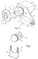
- Figures 2 to 5 show a bracket 1 provided with strengthening ribs 2 which is spot welded along the length of its substantially planar foot portion 3 to the inside of a vehicle door skin 4.
- An upstanding substantially planar portion 5 of the bracket 1 is at right angles to the foot portion 3.
- the upstanding portion is provided with two spaced holes 6 and 7.
- the upstanding portion 5 is further provided with a recess 19 in its upper edge.
- a lock cylinder 9 has a flange 17 at its key-receiving end. The cylinder is inserted through an opening in the door skin 4 and is accommodated in the recess 19.
- a plate 8 is attached to the lock cylinder 9 by a spring clip 10 which enters a peripheral groove 20 situated near the cylinder end (shown in Figure 4 which is in part section for this purpose and also shown in Figure 6).
- the groove 20 extends completely around the cylinder 9, and the clip 10 occupies about 180° of arc when fitted in the groove 20.
- the plate is positioned relative to the flange 17 and to the skin panel 4 with the aid of a tubular spacer sleeve 11.
- the plate 8 is illustrated having an extension 12 and a side plate 13 which serve to brace the plate 8 and also provide a convenient housing for an electrical switch (not shown).
- the plate 8 is provided with two spigots 14 and 15 welded to the plate 8. The spigots are of such length and diameter as to fit and extend through the holes 6 and 7 to thereby locate the plate 8 on the bracket 1.
- the plate 8 is provided with a hole 16 having a shaped, non-circular edge in conformation with the external non-circular shape of the lock cylinder 9. A similar hole is provided through the vehicle door skin 4.
- a flange 17 is provided on the outward end of the lock cylinder and a rubber seal 18 is shown in Figure 3 inserted between the flange and the door skin.
- the spring clip 10 With light pressure being applied in opposing directions to the bezel end of the cylinder and to the plate 8, the spring clip 10 is inserted in the groove 20 to thus attach the plate 8 to the cylinder 9.
- the spring tangs 21 of the clip 10 press against an inner surface of the groove 20 to retain the clip 10 in position and the fingers 22 of the clip 10 extend beyond the groove 20 and the lateral edges of the hole in the plate 8 to prevent the cylinder 9 from being removed from the plate 8.
- the mounting illustrated will also resist pulling out of the cylinder of the lock because the plate 8 is locked to the cylinder by the clip 10, and axial movement of the plate is blocked by the bracket 1.
Landscapes
- Lock And Its Accessories (AREA)
Description
- This invention relates to a mounting arrangement for a lid or door lock and particularly but not exclusively to a mounting arrangement for the lock of a luggage compartment door or tailgate of a motor vehicle.
- Accordingly the present invention will be described below with reference to motor vehicles but it should be appreciated that the invention may be employed for a lock on any lid or door which lock may be susceptible to being forcibly removed particularly by pulling it out to gain access to an opening mechanism.
- While the protection against theft of personal valuables carried in a motor vehicle may often be improved by locking such items in the luggage or rear compartment of the vehicle, such compartments are vulnerable to being broken into.
- Common methods employed for breaking into such compartments include forcible removal of the cylinder of the lock to gain access to the door release mechanism. This may be done by applying high torque to the lock cylinder to wrench it out of its supporting surfaces (sometimes referred to as "torquing out"). Alternatively, high pulling forces may be applied to pull out the cylinder (sometimes referred to generally as "pulling out"). Further, by applying high leverage forces to the cylinder the supporting surfaces may be bent or distorted to permit cylinder removal or to otherwise gain access to the release mechanism (sometimes referred to generally as "bending out").
- While it has been proposed, for example, in US
Patent Specification 4 041 741, to apply a protective plate to the outside of the door to prevent the lock from being pulled out, this is an aesthetically unattractive solution proposal. Further, the proposal of this USPatent 4 041 741 requires additional holes to be produced through the door skin, which adds to potential corrosion sites. - It is also known from US Patent Specification 3 868 836 to provide a bracket within the door to support an inner end of a lock barrel. In this construction, a limited resistance to twisting of the lock mechanism in the panel is achieved by engagement of flats on the barrel with opposite legs of a spring clip.
- According to the present invention, there is provided a mounting arrangement for mounting a lock to a vehicle skin panel, the arrangement comprising a lock cylinder, a hole in the skin panel for receiving the lock cylinder and a bracket which has a foot portion fixed to the skin panel at a distance from the inner surface of the portion of said skin panel on which said hole is provided and an upstanding portion, characterised in that the arrangement includes a plate mounted on the cylinder and fixed against rotation relative to the cylinder, the plate locating behind the bracket so that engagement of the plate against the bracket resists pull-out forces exerted on the cylinder, and wherein the upstanding portion of the bracket is provided with spaced holes and the plate has corresponding spigots which fit in the holes to resist twisting forces exerted on the cylinder.
- According to the present invention, there is also provided a luggage compartment lid including such a mounting arrangement.
- While the bracket, plate and lock barrel are preferably made of metal, other materials having satisfactory strength may alternatively or additionally be employed.
- In this latter context it is important that the bracket can be firmly welded or otherwise fixed to the material of the skin of the enclosure. Accordingly, when the enclosure comprises a compartment of a motor vehicle and having a skin of metal, a metal bracket may be easily welded to the inner surface of the skin, by spot-welding for example, during the process of vehicle manufacture. To this extent, subsequent finishing processes applied to the skin may be applied also to the bracket. The bracket is shaped to permit it to be bonded to the inner surface of the skin while presenting an upstanding portion spaced from the inner skin and on which the plate of the mounting is directly or indirectly locatable. Preferably, the bracket has a substantially planar foot portion that is bonded to the skin and an upstanding substantially planar portion at right angles thereto.
- It is preferred that the plate has a non-circular hole, and the cylinder has a corresponding non-circular part which fits through the hole so that the plate cannot rotate relative to the cylinder. The arrangement preferably also includes a retaining clip adapted to fit into a groove on the end of the cylinder to retain the plate on the cylinder.
- The retaining clip can occupies the groove around at least 120° of arc, preferably substantially 180° of arc.
- The cylinder can have a radially extending flange at its key-receiving end, and a tubular spacer sleeve can be fitted around the cylinder to space the plate from the flange.
- The plate is provided with locating spigots to closely locate into the holes in the bracket with the plate in position and attached to the cylinder to thereby locate the plate on the bracket. It will be seen that in such an arrangement, if a high torque is applied to the cylinder and plate this will be resisted by the spigots.
- It will be appreciated that the thickness and strength of the plate and bracket can readily be tailored to levels necessary to prevent or at least impair pulling out of the cylinder and, as may be desired, torquing out and bending out also. Bending out is clearly resisted by the support given to the cylinder, at a distance spaced from the skin panel by the plate and bracket for example via located spigots and through any direct contact made between the cylinder and the upper edge of the bracket.
- In a preferred embodiment the spacing of at least two of the spigots is preferably such that lines drawn from the centre lines of the spigots to the longitudinal axis of the cylinder and perpendicular thereto form an obtuse angle between one another.
- It will be appreciated that in mounting the lock to for example, a motor vehicle luggage compartment door or tailgate, the end flange on the cylinder may be backed by a resilient seal. Such a seal enables the atmospheric elements to be excluded from around the bezel or flange, provides protection for surrounding paintwork and some resilience to allow for functional tolerances.
- The spigots which may be provided on the plate are preferably of the same material type as the plate and are preferably studs welded on or through the plate but alternatively they may be for example threaded studs or bolts screwed through the plate.
- The present invention will now be further described by way of example, with reference to the accompanying drawings in which:
- Figure 1 is a schematic view of the rear end of a motor vehicle indicating the position of a lock mounting arrangement in accordance with the invention;
- Figure 2 is a forward looking elevation of a mounting arrangement according to the invention;
- Figure 3 illustrates in side elevation and in part section the mounting shown in Figure 1 assembled with a lock cylinder inserted through a vehicle door skin;
- Figure 4 illustrates in part section the manner of attachment of the plate to the cylinder shown in Figure 2;
- Figure 5 is a perspective view of part of the mounting; and
- Figure 6 is an exploded view of a cylinder and spring clip.
- In Figure 1, the position of a lock mounting arrangement according to this invention is indicated by the dotted outline signified by X.
- Figures 2 to 5 show a
bracket 1 provided with strengtheningribs 2 which is spot welded along the length of its substantiallyplanar foot portion 3 to the inside of avehicle door skin 4. An upstanding substantiallyplanar portion 5 of thebracket 1 is at right angles to thefoot portion 3. The upstanding portion is provided with two spacedholes - The
upstanding portion 5 is further provided with arecess 19 in its upper edge. Alock cylinder 9 has aflange 17 at its key-receiving end. The cylinder is inserted through an opening in thedoor skin 4 and is accommodated in therecess 19. - A
plate 8 is attached to thelock cylinder 9 by aspring clip 10 which enters aperipheral groove 20 situated near the cylinder end (shown in Figure 4 which is in part section for this purpose and also shown in Figure 6). thegroove 20 extends completely around thecylinder 9, and theclip 10 occupies about 180° of arc when fitted in thegroove 20. The plate is positioned relative to theflange 17 and to theskin panel 4 with the aid of atubular spacer sleeve 11. Theplate 8 is illustrated having anextension 12 and aside plate 13 which serve to brace theplate 8 and also provide a convenient housing for an electrical switch (not shown). Theplate 8 is provided with twospigots plate 8. The spigots are of such length and diameter as to fit and extend through theholes plate 8 on thebracket 1. - The
plate 8 is provided with ahole 16 having a shaped, non-circular edge in conformation with the external non-circular shape of thelock cylinder 9. A similar hole is provided through thevehicle door skin 4. Aflange 17 is provided on the outward end of the lock cylinder and arubber seal 18 is shown in Figure 3 inserted between the flange and the door skin. - In mounting the
lock cylinder 9 within thedoor skin 4; with thebracket 1 welded to theskin 4, the end of the lock cylinder is passed through the hole provided in theskin 4 until theseal 18 provided under theflange 17 contacts theskin 4. Thetubular spacer sleeve 11 of suitable length is placed over the cylinder and the end of the cylinder remote from theflange 17 is passed through the shaped hole in theplate 8. The plate is pushed onto the cylinder until it contacts the end of thespacer 11 and thespigots holes bracket 1 to thereby establish location of theplate 8 on thebracket 1. With light pressure being applied in opposing directions to the bezel end of the cylinder and to theplate 8, thespring clip 10 is inserted in thegroove 20 to thus attach theplate 8 to thecylinder 9. The spring tangs 21 of theclip 10 press against an inner surface of thegroove 20 to retain theclip 10 in position and thefingers 22 of theclip 10 extend beyond thegroove 20 and the lateral edges of the hole in theplate 8 to prevent thecylinder 9 from being removed from theplate 8. - It will be seen that rotation of the
cylinder 9 relative to thedoor skin 4 will be resisted not only by the non-circular shape of the hole in thedoor skin 4 but more importantly by the shape of the hole in theplate 8 which is itself supported against rotation by thespigots holes bracket 1 through thespigots plate 8; direct support from thebracket 1 is also available in the event of direct contact between thecylinder 9 and therecess 19 at the edge of theupstanding portion 5 of thebracket 1. - The mounting illustrated will also resist pulling out of the cylinder of the lock because the
plate 8 is locked to the cylinder by theclip 10, and axial movement of the plate is blocked by thebracket 1.
Claims (5)
- A mounting arrangement for mounting a lock to a vehicle skin panel, the arrangement comprising a lock cylinder (9), a hole in the skin panel (4) for receiving the lock cylinder and a bracket (1) which has a foot portion (3) fixed to the skin panel (4) at a distance from the inner surface of the portion of said skin panel on which said hole is provided, and an upstanding portion (5), characterised in that the arrangement includes a plate (8) mounted on the cylinder (9) and fixed against rotation relative to the cylinder, the plate locating behind the bracket (1) so that engagement of the plate against the bracket resists pull-out forces exerted on the cylinder, and wherein the upstanding portion (5) of the bracket (1) is provided with spaced holes (6,7) and the plate (8) has corresponding spigots (14,15) which fit in the holes to resist twisting forces exerted on the cylinder (9).
- An arrangement as claimed in Claim 1, characterised in that the plate (8) has a non-circular hole (16), and the cylinder (9) has a corresponding non-circular part which fits through the hole so that the plate cannot rotate relative to the cylinder, the arrangement also including a retaining clip (10) adapted to fit into a groove (20) on the end of the cylinder to retain the plate on the cylinder.
- An arrangement as claimed in Claim 2, characterised in that the retaining clip occupies the groove around at least 120° of arc.
- An arrangement as claimed in any preceding claim, characterised in that the cylinder (9) has a radially extending flange (17) at its key-receiving end, and a tubular spacer sleeve (11) is fitted around the cylinder to space the plate (8) from the flange.
- A luggage compartment lid including a mounting arrangement as claimed in any preceding claim.
Applications Claiming Priority (2)
| Application Number | Priority Date | Filing Date | Title |
|---|---|---|---|
| GB9302513A GB2274873A (en) | 1993-02-09 | 1993-02-09 | Mounting arrangement for lid or door lock |
| GB9302513 | 1993-02-09 |
Publications (2)
| Publication Number | Publication Date |
|---|---|
| EP0611127A1 EP0611127A1 (en) | 1994-08-17 |
| EP0611127B1 true EP0611127B1 (en) | 1997-04-23 |
Family
ID=10730089
Family Applications (1)
| Application Number | Title | Priority Date | Filing Date |
|---|---|---|---|
| EP19940300895 Expired - Lifetime EP0611127B1 (en) | 1993-02-09 | 1994-02-07 | Mounting arrangement for a lid or door lock |
Country Status (3)
| Country | Link |
|---|---|
| EP (1) | EP0611127B1 (en) |
| DE (1) | DE69402734T2 (en) |
| GB (1) | GB2274873A (en) |
Families Citing this family (2)
| Publication number | Priority date | Publication date | Assignee | Title |
|---|---|---|---|---|
| DE29723463U1 (en) * | 1997-02-08 | 1998-10-29 | Kiekert AG, 42579 Heiligenhaus | Motor vehicle door lock |
| US6014876A (en) * | 1999-01-04 | 2000-01-18 | Ford Global Technologies, Inc. | Adjustable locking for hood latch |
Family Cites Families (7)
| Publication number | Priority date | Publication date | Assignee | Title |
|---|---|---|---|---|
| US3868836A (en) * | 1974-03-01 | 1975-03-04 | Ford Motor Co | Deck lid latch and lock assembly |
| CA1019366A (en) * | 1974-08-02 | 1977-10-18 | Ronald J. Mimier | Hardware assembly with attaching clamp |
| US4041741A (en) * | 1975-12-31 | 1977-08-16 | Cintron Carlos U | Automobile trunk guard |
| US4212176A (en) * | 1978-05-30 | 1980-07-15 | Hegedus Charles C | Automobile trunk lock security device |
| JPS5854169A (en) * | 1981-09-25 | 1983-03-31 | 日産自動車株式会社 | Attachment structure of key lock |
| GB2134585B (en) * | 1982-12-13 | 1985-10-23 | Abingdon Classic Car Company L | Improvements in or relating to vehicle door locks |
| GB2203790A (en) * | 1987-04-25 | 1988-10-26 | Harry Cadman | Mounting for lock barrel |
-
1993
- 1993-02-09 GB GB9302513A patent/GB2274873A/en not_active Withdrawn
-
1994
- 1994-02-07 DE DE1994602734 patent/DE69402734T2/en not_active Expired - Fee Related
- 1994-02-07 EP EP19940300895 patent/EP0611127B1/en not_active Expired - Lifetime
Also Published As
| Publication number | Publication date |
|---|---|
| EP0611127A1 (en) | 1994-08-17 |
| DE69402734T2 (en) | 1997-07-31 |
| DE69402734D1 (en) | 1997-05-28 |
| GB2274873A (en) | 1994-08-10 |
| GB9302513D0 (en) | 1993-03-24 |
Similar Documents
| Publication | Publication Date | Title |
|---|---|---|
| US5623842A (en) | Mountable device for securing portable items | |
| US5275030A (en) | Steering wheel mounted anti-theft device for vehicles | |
| JP3992095B2 (en) | Assist grip | |
| JPS5931633B2 (en) | Automotive door handle device | |
| US5062608A (en) | Visor mount | |
| EP0743461B1 (en) | Mounting device | |
| US8925361B2 (en) | Anti-theft device for an access door | |
| US8826768B2 (en) | Steering column assembly | |
| US4511129A (en) | Quarter-window structure for vehicle | |
| US4492101A (en) | Lock cylinder attaching device for vehicle movable closure locks | |
| US5551268A (en) | Retainer assembly for a lock cylinder | |
| US2107015A (en) | Tire cover and lock therefor | |
| EP0611127A1 (en) | Mounting arrangement for a lid or door lock | |
| EP1277900B1 (en) | Vehicle door handle | |
| US4170324A (en) | Bracket mount for lock box | |
| US5768923A (en) | Protective plate for an automobile locking mechanism | |
| KR20020013867A (en) | Automobile and airbag anti-theft device | |
| US5477712A (en) | Automobile anit-theft guard plate | |
| US5689983A (en) | Ignition rack and sector gear for a steering column | |
| US5765414A (en) | Steering wheel lock | |
| GB2310454A (en) | Reinforcing security plate arrangement for locks | |
| KR20060105292A (en) | Car garnish mounting structure | |
| US20020104344A1 (en) | Lock mechanism for deterring access | |
| US8632116B2 (en) | Anti-theft device for an access door | |
| US7805966B1 (en) | Hand brake lock |
Legal Events
| Date | Code | Title | Description |
|---|---|---|---|
| PUAI | Public reference made under article 153(3) epc to a published international application that has entered the european phase |
Free format text: ORIGINAL CODE: 0009012 |
|
| AK | Designated contracting states |
Kind code of ref document: A1 Designated state(s): DE FR GB |
|
| 17P | Request for examination filed |
Effective date: 19950113 |
|
| GRAG | Despatch of communication of intention to grant |
Free format text: ORIGINAL CODE: EPIDOS AGRA |
|
| 17Q | First examination report despatched |
Effective date: 19960711 |
|
| GRAH | Despatch of communication of intention to grant a patent |
Free format text: ORIGINAL CODE: EPIDOS IGRA |
|
| GRAH | Despatch of communication of intention to grant a patent |
Free format text: ORIGINAL CODE: EPIDOS IGRA |
|
| GRAA | (expected) grant |
Free format text: ORIGINAL CODE: 0009210 |
|
| AK | Designated contracting states |
Kind code of ref document: B1 Designated state(s): DE FR GB |
|
| ET | Fr: translation filed | ||
| REF | Corresponds to: |
Ref document number: 69402734 Country of ref document: DE Date of ref document: 19970528 |
|
| PLBE | No opposition filed within time limit |
Free format text: ORIGINAL CODE: 0009261 |
|
| STAA | Information on the status of an ep patent application or granted ep patent |
Free format text: STATUS: NO OPPOSITION FILED WITHIN TIME LIMIT |
|
| 26N | No opposition filed | ||
| PGFP | Annual fee paid to national office [announced via postgrant information from national office to epo] |
Ref country code: GB Payment date: 19990129 Year of fee payment: 6 |
|
| PGFP | Annual fee paid to national office [announced via postgrant information from national office to epo] |
Ref country code: FR Payment date: 19990210 Year of fee payment: 6 |
|
| PGFP | Annual fee paid to national office [announced via postgrant information from national office to epo] |
Ref country code: DE Payment date: 20000122 Year of fee payment: 7 |
|
| PG25 | Lapsed in a contracting state [announced via postgrant information from national office to epo] |
Ref country code: GB Free format text: LAPSE BECAUSE OF NON-PAYMENT OF DUE FEES Effective date: 20000207 |
|
| GBPC | Gb: european patent ceased through non-payment of renewal fee |
Effective date: 20000207 |
|
| PG25 | Lapsed in a contracting state [announced via postgrant information from national office to epo] |
Ref country code: FR Free format text: LAPSE BECAUSE OF NON-PAYMENT OF DUE FEES Effective date: 20001031 |
|
| REG | Reference to a national code |
Ref country code: FR Ref legal event code: ST |
|
| PG25 | Lapsed in a contracting state [announced via postgrant information from national office to epo] |
Ref country code: DE Free format text: LAPSE BECAUSE OF NON-PAYMENT OF DUE FEES Effective date: 20011201 |