EP0611111A1 - Headphone - Google Patents
Headphone Download PDFInfo
- Publication number
- EP0611111A1 EP0611111A1 EP94300836A EP94300836A EP0611111A1 EP 0611111 A1 EP0611111 A1 EP 0611111A1 EP 94300836 A EP94300836 A EP 94300836A EP 94300836 A EP94300836 A EP 94300836A EP 0611111 A1 EP0611111 A1 EP 0611111A1
- Authority
- EP
- European Patent Office
- Prior art keywords
- housing
- opening
- openings
- headphone
- diaphragm
- Prior art date
- Legal status (The legal status is an assumption and is not a legal conclusion. Google has not performed a legal analysis and makes no representation as to the accuracy of the status listed.)
- Granted
Links
Images
Classifications
-
- H—ELECTRICITY
- H04—ELECTRIC COMMUNICATION TECHNIQUE
- H04R—LOUDSPEAKERS, MICROPHONES, GRAMOPHONE PICK-UPS OR LIKE ACOUSTIC ELECTROMECHANICAL TRANSDUCERS; DEAF-AID SETS; PUBLIC ADDRESS SYSTEMS
- H04R1/00—Details of transducers, loudspeakers or microphones
- H04R1/10—Earpieces; Attachments therefor ; Earphones; Monophonic headphones
- H04R1/1016—Earpieces of the intra-aural type
-
- H—ELECTRICITY
- H04—ELECTRIC COMMUNICATION TECHNIQUE
- H04R—LOUDSPEAKERS, MICROPHONES, GRAMOPHONE PICK-UPS OR LIKE ACOUSTIC ELECTROMECHANICAL TRANSDUCERS; DEAF-AID SETS; PUBLIC ADDRESS SYSTEMS
- H04R1/00—Details of transducers, loudspeakers or microphones
- H04R1/10—Earpieces; Attachments therefor ; Earphones; Monophonic headphones
- H04R1/1058—Manufacture or assembly
Definitions
- the present invention relates to headphones. More particularly, the present invention relates to a headphone of an auricle insertion system (so-called inner ear-type headphone) so that a housing thereof is inserted into an auricle and secured therein when the headphone is in use.
- auricle insertion system so that a housing thereof is inserted into an auricle and secured therein when the headphone is in use.
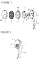
- FIGURES 1 and 2 are views of such conventional headphone
- FIGURE 2 is a perspective view showing the headphone shown in FIGURE 1 is in its assembled state.
- reference numeral 1 designates a housing.
- the housing 1 incorporates therein a speaker unit 3 to which signal lines 2a, 2b are connected.
- the speaker unit 3 is inserted from an opening portion 1b of the housing 1 and accommodated within the housing 1 so as to expose its diaphragm 4 from the opening portion lb.
- the speaker unit 3 has a small diameter, e.g., ten-odd millimeters sufficient so that it can be inserted into an auricle and secured therein.
- the diaphragm 4 provided in front of the speaker unit 3 is driven by a magnetic flux generated from a magnetic circuit 5 provided at the rear portion of the speaker unit 3. More specifically, the diaphragm 4 is connected with a bobbin around which there is wound a voice coil to which an audio signal is supplied via the signal lines 2a, 2b.
- the bobbin and the diaphragm 4 are vibrated by a cooperation of a magnetic flux generated from a magnet provided within the magnetic circuit 5 disposed near the voice coil and an alternating magnetic flux generated by the voice coil on the basis of the audio signal supplied to the voice coil.
- the two signal lines 2a, 2b are led out from a projecting portion la formed at the rear portion of the housing 1 as a single signal line 2.
- a plug (not shown) that is inserted into a headphone jack serving as an audio signal source.
- FIGURE 1 or 2 shows only one headphone, a stereophonic-type headphone needs a pair of right and left headphones, each of which has the housing 1 thus arranged.
- a protector 6 having a number of apertures 6a of relatively large diameters is disposed so as to wholly cover the front surface of the diaphragm 4.
- This protector 6 is formed of a plate-shaped member having a relatively large strength, such as a stainless steel plate or the like to protect the diaphragm 4 or the like from being damaged when a pressure is applied thereto from the outside.
- a grill 7 is disposed on the front surface of the protector 6.
- the grill 7 is made by forming a metal mesh of metal wires into a curved circular mesh structure by a press work.
- the grill 7 is disposed on the front surface of the protector 6 in order to prevent the speaker unit 3 from being smudged by dusts or the like entered from the outside.
- a rubber ring 8 covers the headphone from the grill 7 to the housing 1.
- the rubber ring 8 has an opening portion 8a bored through its predetermined position so that, when this headphone is assembled as a product, the grill 7 is exposed only from this opening portion 8a. A reproduced sound is output from this opening portion 8a.
- the rubber ring 8 is provided in order to prevent the reproduced sound output from the headphone from being leaked to the outside of an auricle, i.e., to prevent a so-called sound leakage.
- the opening portion 8a is smaller than the opening portion 1b of the housing 1.
- the grill made by treating the metal mesh by the press work is used as the grill 7 attached to the headphone is that the grill 7 thus formed has small meshes and is excellent in dust proof property. As a consequence, the headphone of this auricle insertion type can be reduced in thickness and can satisfactorily be used.
- a headphone which incudes a housing, an electro-acoustic transducer, and first and second members.
- the housing has an opening and a projecting portion. The projecting portion lead out a cord from the inside of the housing to the outside of the housing.
- the electro-acoustic transducer is connected to the cord.
- the electro-acoustic transducer has a diaphragm and is housed in the housing to expose the diaphragm through the opening.
- the first member is provided on the electro-acoustic transducer to cover and protect the diaphragm.
- the first member is formed of a plurality of first openings.
- the second member is provided on the opening so as to cover the first member.
- the second member is formed of a plurality of second openings. The diameters of the second openings are smaller than those of the first openings.
- the grill which is attached to the first member provided so as to cover the diaphragm of the electro-acoustic transducer and which serves as the second member having a plurality of openings is made of a synthetic resin material, a fraction defective of the grill itself can be reduced. Furthermore, the manufacturing cost of the headphone can be reduced.
- FIGURES 3, 4, 5 and FIGURES 6A to 6D A headphone according to an embodiment of the present invention will hereinafter be described with reference to FIGURES 3, 4, 5 and FIGURES 6A to 6D.
- FIGURES 3, 4, 5 and FIGURES 6A, 6B like parts corresponding to those of FIGURES 1 and 2 are marked with the same references and therefore need not be described in detail.
- the headphone according to the present invention is applied to the headphone of the auricle insertion system.
- a grill that is attached to this headphone is made of a synthetic resin instead of the conventional metal mesh. A manufacturing process of this grill will be described with reference to FIGURES 6A through 6D.
- a synthetic resin plate 20 having a thickness of about 0.3 [mm] as shown in FIGURE 6A.
- This synthetic resin plate 20 might be formed of a resin material, such as a hard vinyl chloride, ABS (acrylonitrile butadiene styrene) resin, polyethylene terephthalate resin or the like.
- a plurality of very small apertures are sequentially bored through this synthetic resin plate 20 by the punching process in which apertures are punched by using mold pins.
- apertures having a diameter of 0.5 [mm] are bored through the whole surface of the synthetic resin plate 20 at a pitch of 0.65 [mm] with substantially a uniform interval.
- a plurality of curved projecting portions 21 are formed by molding the synthetic resin plate 20 having the apertures bored therethrough by punching using a predetermined mold, i.e., mold corresponding to the shape of the grill under heating. Then, as shown in FIGURE 6D, grills 10 are formed by cutting the respective projecting portions 21 in a circular fashion.
- the grill 10 thus formed is attached to the headphone as follows.
- the housing 1 incorporates therein the speaker unit 3 as shown in FIGURE 5.
- a protector 6 is attached to the front surface side of the speaker unit 3 in order to protect the diaphragm 4 of the speaker unit 3.
- the protector 6 has a plurality of apertures 6a whose diameters are larger than those of the apertures 11 bored through the grill 10 by punching.
- the grill 10 is fitted into the front surface side of the protector 6.
- the grill 10 is fixed to the frame 3a of the speaker unit 3 by some suitable means, such as an adhesive or the like.
- a rubber ring 8 is attached to the housing 1 so as to cover the whole surface of the grill 10 and the housing 1 at its front surface side in which the opening portion 1b is formed under the condition that the grill 10 is attached to the frame 3a of the speaker unit 3.
- the rubber ring 8 is attached to the housing 1 by engagement between a concave portion 8b formed on the inner peripheral side of the rubber ring 8 and a projecting portion 1c formed on the outer periphery of the housing 1.
- the grill having satisfactory shape can be manufactured by a simple process with a small fraction defective.
- the apertures that are formed by punching are very small in diameter unlike the case that apertures are formed by the injection molding process of a synthetic resin or the like.
- Such apertures that are formed by punching can achieve a dust proof effect similar to that achieved by the metal mesh and can be considerably reduced in thickness. Therefore, the headphone of the auricle insertion type according to the present invention can be prevented from being increased in thickness as compared with the conventional headphone of auricle insertion type.
- the headphone according to the present invention can satisfactorily be used. Moreover, disadvantages in the manufacturing process, such as an frayed edge of the grill formed by the metal mesh, can be removed and the headphone according to the present invention can be manufactured with a simple process with a small fraction defective. The manufacturing cost of the headphone can be reduced by using the grill according to the embodiment of the present invention. With the employment of the grill according to this embodiment, the metal parts can be prevented from being exposed on the sound radiation portion of the headphone. Therefore, the headphone according to this embodiment can satisfactorily be used by users who have an eruption on the skin with metals, i.e., those who are allergic to metals.
- the present invention is not limited thereto and the apertures may be bored therethrough at irregular intervals.
- the apertures 11 may be disposed at irregular intervals in order to obtain satisfactory playback characteristics. In this case, apertures which are different in diameter may be disposed on the grill.
- the present invention is not limited thereto and the following variant also is possible. That is, a plurality of very small apertures may be bored through a thinner resin film having a thickness of about 50 [ ⁇ m] by punching and then this thinner resin film may be molded as a grill of a predetermined shape by a press-treatment.
- the present invention is applied to the headphone in which the rubber ring is attached to the front surface of the grill as described above, the present invention is not limited thereto and may be applied to a headphone of the shape such that the grill is directly exposed without the rubber ring.
Landscapes
- Physics & Mathematics (AREA)
- Engineering & Computer Science (AREA)
- Acoustics & Sound (AREA)
- Signal Processing (AREA)
- Headphones And Earphones (AREA)
- Details Of Audible-Bandwidth Transducers (AREA)
Abstract
Description
- The present invention relates to headphones. More particularly, the present invention relates to a headphone of an auricle insertion system (so-called inner ear-type headphone) so that a housing thereof is inserted into an auricle and secured therein when the headphone is in use.
- Headphones of so-called auricle insertion type have hitherto been proposed as described in U.S. Patent Nos. 4,736,435, 4,429,194 and 4,646,872, for example. The conventional headphone of this auricle insertion type is arranged as shown in FIGURES 1 and 2. FIGURE 1 is an exploded perspective view of such conventional headphone, and FIGURE 2 is a perspective view showing the headphone shown in FIGURE 1 is in its assembled state. In FIGURES 1 and 2,
reference numeral 1 designates a housing. Thehousing 1 incorporates therein aspeaker unit 3 to whichsignal lines speaker unit 3 is inserted from anopening portion 1b of thehousing 1 and accommodated within thehousing 1 so as to expose itsdiaphragm 4 from the opening portion lb. Thespeaker unit 3 has a small diameter, e.g., ten-odd millimeters sufficient so that it can be inserted into an auricle and secured therein. Thediaphragm 4 provided in front of thespeaker unit 3 is driven by a magnetic flux generated from amagnetic circuit 5 provided at the rear portion of thespeaker unit 3. More specifically, thediaphragm 4 is connected with a bobbin around which there is wound a voice coil to which an audio signal is supplied via thesignal lines diaphragm 4 are vibrated by a cooperation of a magnetic flux generated from a magnet provided within themagnetic circuit 5 disposed near the voice coil and an alternating magnetic flux generated by the voice coil on the basis of the audio signal supplied to the voice coil. - The two
signal lines housing 1 as asingle signal line 2. To the end portion of thesignal line 2 is connected a plug (not shown) that is inserted into a headphone jack serving as an audio signal source. Although FIGURE 1 or 2 shows only one headphone, a stereophonic-type headphone needs a pair of right and left headphones, each of which has thehousing 1 thus arranged. - With the above-mentioned structure, a reproduced sound is radiated forwardly on the basis of the vibration of the
diaphragm 4 of thespeaker unit 3. Aprotector 6 having a number of apertures 6a of relatively large diameters is disposed so as to wholly cover the front surface of thediaphragm 4. Thisprotector 6 is formed of a plate-shaped member having a relatively large strength, such as a stainless steel plate or the like to protect thediaphragm 4 or the like from being damaged when a pressure is applied thereto from the outside. - A
grill 7 is disposed on the front surface of theprotector 6. Thegrill 7 is made by forming a metal mesh of metal wires into a curved circular mesh structure by a press work. Thegrill 7 is disposed on the front surface of theprotector 6 in order to prevent thespeaker unit 3 from being smudged by dusts or the like entered from the outside. - A
rubber ring 8 covers the headphone from thegrill 7 to thehousing 1. Therubber ring 8 has anopening portion 8a bored through its predetermined position so that, when this headphone is assembled as a product, thegrill 7 is exposed only from thisopening portion 8a. A reproduced sound is output from thisopening portion 8a. Therubber ring 8 is provided in order to prevent the reproduced sound output from the headphone from being leaked to the outside of an auricle, i.e., to prevent a so-called sound leakage. Theopening portion 8a is smaller than theopening portion 1b of thehousing 1. - The reason that the grill made by treating the metal mesh by the press work is used as the
grill 7 attached to the headphone is that thegrill 7 thus formed has small meshes and is excellent in dust proof property. As a consequence, the headphone of this auricle insertion type can be reduced in thickness and can satisfactorily be used. - However, such grill made by treating the metal mesh by the press work is expensive and needs much time and labor when such grill is processed. More specifically, the expensive metal mesh in which metal wires are formed as a mesh structure is used as a material and much time and labor are required to form this metal mesh material into the curved circular grill by the press work. Particularly, when the metal mesh is cut into a circular grill, it is frequently observed that metal wires around the edge of the curved circular grill become loose. Therefore, it is unavoidable that a fraction defective of the grill is increased.
- According to an aspect of the present invention, there is provided a headphone which incudes a housing, an electro-acoustic transducer, and first and second members. The housing has an opening and a projecting portion. The projecting portion lead out a cord from the inside of the housing to the outside of the housing. The electro-acoustic transducer is connected to the cord. The electro-acoustic transducer has a diaphragm and is housed in the housing to expose the diaphragm through the opening. The first member is provided on the electro-acoustic transducer to cover and protect the diaphragm. The first member is formed of a plurality of first openings. The second member is provided on the opening so as to cover the first member. The second member is formed of a plurality of second openings. The diameters of the second openings are smaller than those of the first openings.
- According to the present invention, since the grill which is attached to the first member provided so as to cover the diaphragm of the electro-acoustic transducer and which serves as the second member having a plurality of openings is made of a synthetic resin material, a fraction defective of the grill itself can be reduced. Furthermore, the manufacturing cost of the headphone can be reduced.
- The present invention will be further described with reference to the following description of exemplary embodiments and the accompanying drawings, in which:
- FIGURE 1 is an exploded perspective view showing a structure of a conventional headphone;
- FIGURE 2 is a perspective view showing the structure of the conventional headphone shown in FIGURE 1;
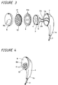
- FIGURE 3 is an exploded perspective view showing a headphone according to an embodiment of the present invention;
- FIGURE 4 is a perspective view showing the headphone according to the embodiment of the present invention;
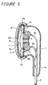
- FIGURE 5 is a cross-sectional view showing the headphone according to the embodiment of the present invention;
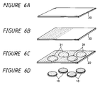
- FIGURES 6A through 6D are respectively diagrams used to explain manufacturing processes of a grill according to the present invention, wherein FIGURE 6A shows a synthetic resin plate which serves as a material for grill, FIGURE 6B shows a synthetic resin plate that was processed by punching, FIGURE 6C shows the synthetic resin plate on which the projecting portions are formed, and FIGURE 6D shows completed grills; and
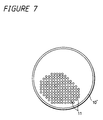
- FIGURE 7 is a diagram showing a modified example of the grill according to the present invention.
- A headphone according to an embodiment of the present invention will hereinafter be described with reference to FIGURES 3, 4, 5 and FIGURES 6A to 6D. In FIGURES 3, 4, 5 and FIGURES 6A, 6B, like parts corresponding to those of FIGURES 1 and 2 are marked with the same references and therefore need not be described in detail.
- In this embodiment, the headphone according to the present invention is applied to the headphone of the auricle insertion system. In this embodiment, a grill that is attached to this headphone is made of a synthetic resin instead of the conventional metal mesh. A manufacturing process of this grill will be described with reference to FIGURES 6A through 6D.
- Initially, there is prepared a
synthetic resin plate 20 having a thickness of about 0.3 [mm] as shown in FIGURE 6A. Thissynthetic resin plate 20 might be formed of a resin material, such as a hard vinyl chloride, ABS (acrylonitrile butadiene styrene) resin, polyethylene terephthalate resin or the like. Then, as shown in FIGURE 6B, a plurality of very small apertures are sequentially bored through thissynthetic resin plate 20 by the punching process in which apertures are punched by using mold pins. In this embodiment, apertures having a diameter of 0.5 [mm], for example, are bored through the whole surface of thesynthetic resin plate 20 at a pitch of 0.65 [mm] with substantially a uniform interval. - As shown in FIGURE 6C, a plurality of curved projecting
portions 21 are formed by molding thesynthetic resin plate 20 having the apertures bored therethrough by punching using a predetermined mold, i.e., mold corresponding to the shape of the grill under heating. Then, as shown in FIGURE 6D,grills 10 are formed by cutting the respective projectingportions 21 in a circular fashion. - The
grill 10 thus formed is attached to the headphone as follows. Thehousing 1 incorporates therein thespeaker unit 3 as shown in FIGURE 5. Aprotector 6 is attached to the front surface side of thespeaker unit 3 in order to protect thediaphragm 4 of thespeaker unit 3. Theprotector 6 has a plurality of apertures 6a whose diameters are larger than those of theapertures 11 bored through thegrill 10 by punching. Thegrill 10 is fitted into the front surface side of theprotector 6. Thegrill 10 is fixed to theframe 3a of thespeaker unit 3 by some suitable means, such as an adhesive or the like. Arubber ring 8 is attached to thehousing 1 so as to cover the whole surface of thegrill 10 and thehousing 1 at its front surface side in which theopening portion 1b is formed under the condition that thegrill 10 is attached to theframe 3a of thespeaker unit 3. Therubber ring 8 is attached to thehousing 1 by engagement between aconcave portion 8b formed on the inner peripheral side of therubber ring 8 and a projectingportion 1c formed on the outer periphery of thehousing 1. When the headphone is assembled, as shown in FIGURE 4, theapertures 11 on thegrill 10 are exposed to the outside from theopening portion 8a of therubber ring 8. - According to the embodiment of the present invention, since the synthetic resin plate having a plurality of very small apertures bored therethrough by punching is molded by the press-treatment and used as the
grill 10, the grill having satisfactory shape can be manufactured by a simple process with a small fraction defective. The apertures that are formed by punching are very small in diameter unlike the case that apertures are formed by the injection molding process of a synthetic resin or the like. Such apertures that are formed by punching can achieve a dust proof effect similar to that achieved by the metal mesh and can be considerably reduced in thickness. Therefore, the headphone of the auricle insertion type according to the present invention can be prevented from being increased in thickness as compared with the conventional headphone of auricle insertion type. Also, the headphone according to the present invention can satisfactorily be used. Moreover, disadvantages in the manufacturing process, such as an frayed edge of the grill formed by the metal mesh, can be removed and the headphone according to the present invention can be manufactured with a simple process with a small fraction defective. The manufacturing cost of the headphone can be reduced by using the grill according to the embodiment of the present invention. With the employment of the grill according to this embodiment, the metal parts can be prevented from being exposed on the sound radiation portion of the headphone. Therefore, the headphone according to this embodiment can satisfactorily be used by users who have an eruption on the skin with metals, i.e., those who are allergic to metals. - While the apertures are bored through the whole surface of the grill at the uniform interval as described above, the present invention is not limited thereto and the apertures may be bored therethrough at irregular intervals. As shown in FIGURE 7, for example, it is possible to form a grill 10' having
apertures 11 concentrated at its portion corresponding to theopening portion 8a of therubber ring 8. Alternatively, considering playback characteristics of the reproduced sound, theapertures 11 may be disposed at irregular intervals in order to obtain satisfactory playback characteristics. In this case, apertures which are different in diameter may be disposed on the grill. - Further, while the thin synthetic resin plate is processed and used as the grill as described above, the present invention is not limited thereto and the following variant also is possible. That is, a plurality of very small apertures may be bored through a thinner resin film having a thickness of about 50 [µm] by punching and then this thinner resin film may be molded as a grill of a predetermined shape by a press-treatment.
- Furthermore, while the present invention is applied to the headphone in which the rubber ring is attached to the front surface of the grill as described above, the present invention is not limited thereto and may be applied to a headphone of the shape such that the grill is directly exposed without the rubber ring.
- Having described a preferred embodiment of the invention with reference to the accompanying drawings, it is to be understood that the invention is not limited to that precise embodiment and that various changes and modifications could be effected therein by one skilled in the art without departing from the scope of the invention as defined in the appended claims.
Claims (7)
- A headphone comprising:
a housing having an opening and a projecting portion, said projecting portion leading out a cord from the inside of said housing to the outside of said housing;
an electro-acoustic transducer connected to said cord, said electro-acoustic transducer having a diaphragm and housed in said housing to expose said diaphragm from said opening;
a first member provided on said electro-acoustic transducer to cover and protect said diaphragm, said first member being formed with a plurality of first openings; and
a second member provided on said opening so as to cover said first member, said second member being formed with a plurality of openings, the diameters of said second openings being smaller than those of said first openings. - A headphone according to claim 1, wherein said second member is made of a synthetic resin.
- A headphone according to claim 1 or 2, wherein said second openings are provided at irregular intervals.
- A headphone according to claim 1, 2 or 3, further comprising a further member provided on said housing so as to cover said opening, said further member being made of an elastic material and having an aperture.
- A headphone comprising:
a housing having an opening and a holding portion, said holding portion holding a cord;
an electro-acoustic transducer connected to said cord, said electro-acoustic transducer having a diaphragm and housed in said housing to expose said diaphragm from said opening;
a protector provided on said opening so as to cover and protect said diaphragm, said protector comprising:
a first member being formed of a plurality of first openings;
a second member provided on said opening so as to cover said first member, said second member being made of a synthetic resin and having a plurality of second openings; and
a third member provided on said housing so as to cover said opening, said third member being made of an elastic material and having an aperture. - A headphone according to claim 5, wherein said second openings are provided at irregular intervals.
- A headphone comprising:
an electro-acoustic transducer having a diaphragm and to which a signal is input through a cord;
an accommodating portion shaped in such a way as to be accommodated in a concave portion of an auricle and in which said electro-acoustic transducer is accommodated;
a housing having a projecting portion connected to said accommodating portion, said projecting portion leading out a cord from the inside of said housing to the outside of said housing, said accommodating portion having a first opening, said diaphragm being exposed through said opening to the outside, and said projecting portion being formed on the rear surface side of said accommodating portion;
a first member being made of a metal material so as to cover the whole surface of said diaphragm and said first opening, said first member having a plurality of first openings;
a second member being provided on said first member so as to cover said first member and made of a synthetic resin material, said second member having a plurality of second openings whose diameters are smaller than those of said first openings formed on said housing; and
a third member being provided on said housing so as to cover said housing having said second member at its portion in which said first opening is formed, said third member having a second opening smaller than said first opening.
Applications Claiming Priority (2)
| Application Number | Priority Date | Filing Date | Title |
|---|---|---|---|
| JP20883/93 | 1993-02-09 | ||
| JP5020883A JPH06237499A (en) | 1993-02-09 | 1993-02-09 | Headphone |
Publications (2)
| Publication Number | Publication Date |
|---|---|
| EP0611111A1 true EP0611111A1 (en) | 1994-08-17 |
| EP0611111B1 EP0611111B1 (en) | 1998-09-09 |
Family
ID=12039601
Family Applications (1)
| Application Number | Title | Priority Date | Filing Date |
|---|---|---|---|
| EP94300836A Expired - Lifetime EP0611111B1 (en) | 1993-02-09 | 1994-02-04 | Headphone |
Country Status (5)
| Country | Link |
|---|---|
| US (1) | US5420935A (en) |
| EP (1) | EP0611111B1 (en) |
| JP (1) | JPH06237499A (en) |
| KR (1) | KR940020862A (en) |
| DE (1) | DE69413087T2 (en) |
Cited By (8)
| Publication number | Priority date | Publication date | Assignee | Title |
|---|---|---|---|---|
| CN102547497A (en) * | 2010-12-14 | 2012-07-04 | 富泰华工业(深圳)有限公司 | Loudspeaker hole dust screen and fixing method thereof, and electronic device using loudspeaker hole dust screen |
| GB2505979A (en) * | 2012-09-14 | 2014-03-19 | Wolfson Microelectronics Plc | Cable inlet structure for an earphone |
| EP2606659A4 (en) * | 2010-08-20 | 2014-03-26 | Skullcandy Inc | AUDIO HEADS WITH EARPHONES AND BUTTONS HAVING A MORE PRECISE CURVATURE |
| CN104066029A (en) * | 2014-06-24 | 2014-09-24 | 中山市天键电声有限公司 | Method for fixing dustproof net on headset surface cover through hot pressing |
| US9055365B2 (en) | 2010-01-06 | 2015-06-09 | Skullcandy, Inc. | Earbuds securable to users' outer ears and related headphone systems and methods |
| US9532126B1 (en) | 2010-01-06 | 2016-12-27 | Skullcandy, Inc. | Audio earbud headphone for improved in-ear retention |
| CN109922183A (en) * | 2019-02-21 | 2019-06-21 | 维沃移动通信有限公司 | A kind of receiver dust cover and terminal device |
| EP4195689A4 (en) * | 2020-08-20 | 2024-01-24 | Huawei Technologies Co., Ltd. | EARPHONE |
Families Citing this family (90)
| Publication number | Priority date | Publication date | Assignee | Title |
|---|---|---|---|---|
| US5533131A (en) * | 1994-05-23 | 1996-07-02 | Kury; C. A. | Anti-eavesdropping device |
| US5988812A (en) * | 1997-10-27 | 1999-11-23 | Sony Corporation | Headphone eyeglasses |
| CN1138447C (en) * | 1998-02-16 | 2004-02-11 | 林仲宇 | Earphone without acoustic hearing loss and impulsive noise |
| US6134336A (en) * | 1998-05-14 | 2000-10-17 | Motorola, Inc. | Integrated speaker assembly of a portable electronic device |
| USD430860S (en) * | 1999-06-22 | 2000-09-12 | Samsung Electro-Mechanics Co., Ltd. | Ear-microphone for cellular phones |
| USD430547S (en) * | 1999-10-14 | 2000-09-05 | Samsung Electro-Mechanics Co., Ltd. | Ear-microphone for cellular phones |
| USD431030S (en) * | 1999-10-14 | 2000-09-19 | Samsung Electro-Mechanics Co., Ltd. | Ear-microphone for cellular phones |
| US6760458B1 (en) * | 2000-11-15 | 2004-07-06 | Gn Netcom, Inc. | Headset and method of manufacturing headsets that utilize a single transceiver form-factor design with a number of different housing styles |
| JP2002199072A (en) * | 2000-12-27 | 2002-07-12 | Seiko Instruments Inc | Arm-mounted type communication unit |
| US7087162B2 (en) * | 2001-09-24 | 2006-08-08 | Peddicord Donald B | Accessible well for brine tank |
| AU2002951326A0 (en) * | 2002-09-11 | 2002-09-26 | Innotech Pty Ltd | Communication apparatus and helmet |
| US6905000B1 (en) * | 2003-01-31 | 2005-06-14 | Plantronics, Inc. | Faceplate cover |
| JP2006279959A (en) * | 2005-03-25 | 2006-10-12 | Shogen Nan | Automatic control earphone system employing electrostatic capacitance sensor |
| USD533868S1 (en) * | 2005-04-22 | 2006-12-19 | Sony Corporation | Earphone |
| USD533867S1 (en) * | 2005-04-22 | 2006-12-19 | Sony Corporation | Earphone |
| US7864974B2 (en) * | 2005-06-29 | 2011-01-04 | Lu-Cheng Chen | Earphone device integrated with microphone |
| JP4690856B2 (en) * | 2005-10-28 | 2011-06-01 | パイオニア株式会社 | Speaker grill and speaker device |
| US7801571B2 (en) * | 2005-11-30 | 2010-09-21 | Motorola Mobility, Inc. | Multi-use acoustic leak path system |
| USD554109S1 (en) * | 2006-08-17 | 2007-10-30 | Microsoft Corporation | Pair of earphones |
| TW200829053A (en) * | 2006-12-21 | 2008-07-01 | Global Target Entpr Inc | Thin-film type sound source output apparatus |
| TW200939853A (en) * | 2008-03-14 | 2009-09-16 | Cotron Corp | Speaker structure capable of adjusting ventilation of a chamber therein |
| US8027501B2 (en) * | 2008-05-19 | 2011-09-27 | Merry Electronics Co., Ltd. | Headphone |
| USD603378S1 (en) * | 2008-06-17 | 2009-11-03 | Motorola, Inc. | Headset for a communication device |
| CA130063S (en) * | 2008-10-07 | 2009-10-23 | Audio Technica Also Known As Audio Technica Corp Kk | Headphones |
| USD619539S1 (en) * | 2008-12-04 | 2010-07-13 | Sony Corporation | Headphone |
| JP4831176B2 (en) * | 2009-01-29 | 2011-12-07 | 日本ビクター株式会社 | headphone |
| CN201393289Y (en) * | 2009-02-18 | 2010-01-27 | 聂浩 | The structure of the earphone |
| USD624057S1 (en) * | 2010-01-06 | 2010-09-21 | Skullcandy, Inc. | Audio ear bud headphone with extended curvature |
| US20120025335A1 (en) * | 2010-07-28 | 2012-02-02 | Avago Technologies Wireless Ip (Singapore) Pte. Ltd. | Microelectromechanical systems (mems) package |
| USD657779S1 (en) * | 2010-11-24 | 2012-04-17 | JVC Kenwood Corporation | Earphone |
| USD652821S1 (en) * | 2011-01-03 | 2012-01-24 | Monster Cable Products, Inc. | Headphone |
| USD652823S1 (en) * | 2011-04-15 | 2012-01-24 | Hon Hai Precision Industry Co., Ltd. | Earphone |
| USD689471S1 (en) | 2011-10-07 | 2013-09-10 | SMS Audio LLC | Pair of earbuds |
| USD666996S1 (en) * | 2011-10-07 | 2012-09-11 | SMS Audio LLC | Earbud head phone |
| USD686597S1 (en) * | 2011-11-09 | 2013-07-23 | Monster, Llc | Headphone |
| US9288591B1 (en) | 2012-03-14 | 2016-03-15 | Google Inc. | Bone-conduction anvil and diaphragm |
| USD688650S1 (en) * | 2012-03-26 | 2013-08-27 | Hon Hai Precision Industry Co., Ltd. | Earphone |
| USD701195S1 (en) * | 2012-06-26 | 2014-03-18 | Sony Corporation | Earphone |
| USD694220S1 (en) * | 2012-08-21 | 2013-11-26 | Monster, Llc | Headphone |
| USD689848S1 (en) * | 2012-08-28 | 2013-09-17 | Monster, Llc | Headphone |
| USD820809S1 (en) | 2012-09-08 | 2018-06-19 | Apple Inc. | Earphone |
| USD681015S1 (en) * | 2012-09-08 | 2013-04-30 | Apple Inc. | Earphone |
| USD1021863S1 (en) * | 2012-09-11 | 2024-04-09 | Apple Inc. | Packaging with earphones |
| USD687418S1 (en) * | 2012-10-24 | 2013-08-06 | Zagg Intellectual Property Holding Co., Inc. | Earbud |
| USD695722S1 (en) * | 2012-11-14 | 2013-12-17 | Aac Acoustic Technologies (Shenzhen) Co., Ltd. | Earphone |
| USD695723S1 (en) * | 2012-11-20 | 2013-12-17 | Panasonic Corporation | Earphone |
| USD698761S1 (en) * | 2013-01-10 | 2014-02-04 | Aac Acoustic Technologies (Shenzhen) Co., Ltd. | Earphone |
| USD741287S1 (en) * | 2013-09-13 | 2015-10-20 | Samsung Electronics Co., Ltd. | Earphone |
| USD716257S1 (en) * | 2013-10-21 | 2014-10-28 | Arlene Sarkoyan | Dual headphone with single connector |
| USD746790S1 (en) * | 2014-03-06 | 2016-01-05 | Headbox Llc | Headphone |
| JP1526035S (en) * | 2014-03-31 | 2015-06-15 | ||
| US9573165B2 (en) | 2014-08-22 | 2017-02-21 | Apple Inc. | Hydrophobic mesh cover |
| USD743948S1 (en) * | 2014-11-10 | 2015-11-24 | Peag, LLC | Pair of earbuds |
| USD755759S1 (en) * | 2014-11-14 | 2016-05-10 | Hejin Cai | In-ear headphone |
| TWD176083S (en) * | 2014-12-29 | 2016-06-01 | 三星電子股份有限公司 | Portion of earphone |
| US9955244B2 (en) * | 2015-05-27 | 2018-04-24 | Apple Inc. | Electronic device with speaker enclosure sensor |
| USD784961S1 (en) * | 2015-06-05 | 2017-04-25 | Logitech Europe, S.A. | Ear cushion |
| JP1568084S (en) * | 2015-12-24 | 2017-01-30 | ||
| JP1558222S (en) * | 2016-02-05 | 2016-09-12 | ||
| JP1566783S (en) * | 2016-02-09 | 2017-01-16 | ||
| JP1567217S (en) * | 2016-02-09 | 2017-01-16 | ||
| USD820808S1 (en) * | 2016-03-02 | 2018-06-19 | Zound Industries International Ab | Headphone headset |
| USD804455S1 (en) * | 2016-03-25 | 2017-12-05 | 1More Inc. | Earphone |
| JP1573559S (en) * | 2016-08-02 | 2017-04-10 | ||
| JP1580450S (en) * | 2016-08-31 | 2017-07-03 | ||
| USD801314S1 (en) | 2016-09-06 | 2017-10-31 | Apple Inc. | Pair of earphones |
| US10595107B2 (en) | 2016-09-20 | 2020-03-17 | Apple Inc. | Speaker module architecture |
| USD828823S1 (en) * | 2016-09-26 | 2018-09-18 | Shenzhen Dacom Electronics Co., Ltd. | Earphone |
| USD810047S1 (en) * | 2016-10-05 | 2018-02-13 | Kingston Digital, Inc. | Earphone tip |
| TWD184087S (en) * | 2016-10-05 | 2017-07-01 | 金士頓數位股份有限公司 | Portion of an earphone |
| USD832824S1 (en) * | 2016-12-26 | 2018-11-06 | Samsung Electronics Co., Ltd. | Earphone |
| USD841616S1 (en) * | 2016-12-30 | 2019-02-26 | Head-Direct (Kunshan) Company Limited | Audio listening system |
| USD841615S1 (en) * | 2016-12-30 | 2019-02-26 | Head-Direct (Kunshan) Company Limited | Audio listening system |
| JP1596449S (en) * | 2017-08-10 | 2018-02-05 | ||
| USD869430S1 (en) * | 2018-01-29 | 2019-12-10 | Amazon Technologies, Inc. | Headphones |
| USD830345S1 (en) * | 2018-04-26 | 2018-10-09 | Hejin Cai | Earphone |
| JP1621749S (en) * | 2018-08-22 | 2019-01-15 | ||
| USD897995S1 (en) | 2018-08-29 | 2020-10-06 | Logitech Europe S.A. | Headphone |
| USD876399S1 (en) | 2018-09-27 | 2020-02-25 | Logitech Europe S.A. | Single piece headphone |
| USD906297S1 (en) | 2019-09-13 | 2020-12-29 | Apple Inc. | Pair of earphones |
| USD909347S1 (en) | 2019-09-20 | 2021-02-02 | Apple Inc. | Earphone |
| USD923658S1 (en) | 2019-10-02 | 2021-06-29 | Apple Inc. | Electronic device with graphical user interface |
| USD930623S1 (en) * | 2020-08-20 | 2021-09-14 | Shenzhen Nearbyexpress Technology Development Company Limited | Earphone and earphone box |
| USD978842S1 (en) | 2020-11-11 | 2023-02-21 | Apple Inc. | Pair of earphones |
| USD934204S1 (en) * | 2021-03-15 | 2021-10-26 | Guangzhou Fairy Tale Electronics Co., Ltd. | Pair of earphones |
| USD1000424S1 (en) * | 2021-03-19 | 2023-10-03 | Oneplus Technology (Shenzhen) Co., Ltd. | Wireless earphone |
| JP1700976S (en) * | 2021-06-16 | 2021-11-29 | ||
| USD999194S1 (en) * | 2021-08-10 | 2023-09-19 | Shenzhen Shengyuan Tech Ltd | Wireless earphone |
| USD1026855S1 (en) * | 2022-07-27 | 2024-05-14 | Cresyn Co., Ltd. | Headset |
| USD1060304S1 (en) * | 2023-03-24 | 2025-02-04 | Logitech Europe S.A. | Headset |
Citations (3)
| Publication number | Priority date | Publication date | Assignee | Title |
|---|---|---|---|---|
| FR2547967A1 (en) * | 1983-06-24 | 1984-12-28 | Horlogerie Photograph Fse | Transmitter or receiver capsule for telephone set provided with a mechanical protection device |
| GB2220819A (en) * | 1988-07-12 | 1990-01-17 | Sony Corp | Electroacoustic transducer |
| EP0373816A2 (en) * | 1988-12-12 | 1990-06-20 | Sony Corporation | Electroacoustic transducer apparatus |
Family Cites Families (7)
| Publication number | Priority date | Publication date | Assignee | Title |
|---|---|---|---|---|
| US2293078A (en) * | 1939-12-05 | 1942-08-18 | B A Proctor Company Inc | Microphone |
| US2346226A (en) * | 1941-09-16 | 1944-04-11 | British Rola Ltd | Protective cover for apertures for loud-speaking instruments, microphones, and otherarticles |
| US2423014A (en) * | 1943-05-10 | 1947-06-24 | Permoflux Corp | Pressure-equalizing housing for transducers |
| US4058688A (en) * | 1975-05-27 | 1977-11-15 | Matsushita Electric Industrial Co., Ltd. | Headphone |
| JPS574880U (en) * | 1980-06-06 | 1982-01-11 | ||
| CA1165248A (en) * | 1980-10-31 | 1984-04-10 | Shingo Watanabe | Electro-acoustic transducer |
| JPH0733508Y2 (en) * | 1984-10-31 | 1995-07-31 | ソニー株式会社 | earphone |
-
1993
- 1993-02-09 JP JP5020883A patent/JPH06237499A/en active Pending
-
1994
- 1994-02-01 US US08/189,711 patent/US5420935A/en not_active Expired - Lifetime
- 1994-02-04 DE DE69413087T patent/DE69413087T2/en not_active Expired - Fee Related
- 1994-02-04 EP EP94300836A patent/EP0611111B1/en not_active Expired - Lifetime
- 1994-02-08 KR KR1019940002429A patent/KR940020862A/en not_active Withdrawn
Patent Citations (3)
| Publication number | Priority date | Publication date | Assignee | Title |
|---|---|---|---|---|
| FR2547967A1 (en) * | 1983-06-24 | 1984-12-28 | Horlogerie Photograph Fse | Transmitter or receiver capsule for telephone set provided with a mechanical protection device |
| GB2220819A (en) * | 1988-07-12 | 1990-01-17 | Sony Corp | Electroacoustic transducer |
| EP0373816A2 (en) * | 1988-12-12 | 1990-06-20 | Sony Corporation | Electroacoustic transducer apparatus |
Cited By (15)
| Publication number | Priority date | Publication date | Assignee | Title |
|---|---|---|---|---|
| US9532126B1 (en) | 2010-01-06 | 2016-12-27 | Skullcandy, Inc. | Audio earbud headphone for improved in-ear retention |
| US9055365B2 (en) | 2010-01-06 | 2015-06-09 | Skullcandy, Inc. | Earbuds securable to users' outer ears and related headphone systems and methods |
| EP2606659A4 (en) * | 2010-08-20 | 2014-03-26 | Skullcandy Inc | AUDIO HEADS WITH EARPHONES AND BUTTONS HAVING A MORE PRECISE CURVATURE |
| CN102547497A (en) * | 2010-12-14 | 2012-07-04 | 富泰华工业(深圳)有限公司 | Loudspeaker hole dust screen and fixing method thereof, and electronic device using loudspeaker hole dust screen |
| US8631558B2 (en) | 2010-12-14 | 2014-01-21 | Fu Tai Hua Industry (Shenzhen) Co., Ltd. | Method for making dust cover, electronic device, and method for fixing dust cover to electronic device housing |
| GB2505979B (en) * | 2012-09-14 | 2015-02-18 | Wolfson Microelectronics Plc | Earphone |
| GB2505919B (en) * | 2012-09-14 | 2015-02-18 | Wolfson Microelectronics Plc | Earphone |
| GB2505919A (en) * | 2012-09-14 | 2014-03-19 | Wolfson Microelectronics Plc | Cable inlet structure for an earphone |
| US9245515B2 (en) | 2012-09-14 | 2016-01-26 | Cirrus Logic International Semiconductor Ltd. | Earphone |
| GB2505979A (en) * | 2012-09-14 | 2014-03-19 | Wolfson Microelectronics Plc | Cable inlet structure for an earphone |
| CN104066029A (en) * | 2014-06-24 | 2014-09-24 | 中山市天键电声有限公司 | Method for fixing dustproof net on headset surface cover through hot pressing |
| CN104066029B (en) * | 2014-06-24 | 2018-07-20 | 中山市天键电声有限公司 | A kind of method that Air Filter is fixed in the hot pressing of earphone cover |
| CN109922183A (en) * | 2019-02-21 | 2019-06-21 | 维沃移动通信有限公司 | A kind of receiver dust cover and terminal device |
| EP4195689A4 (en) * | 2020-08-20 | 2024-01-24 | Huawei Technologies Co., Ltd. | EARPHONE |
| US12368989B2 (en) | 2020-08-20 | 2025-07-22 | Huawei Technologies Co., Ltd. | Headset |
Also Published As
| Publication number | Publication date |
|---|---|
| US5420935A (en) | 1995-05-30 |
| DE69413087D1 (en) | 1998-10-15 |
| DE69413087T2 (en) | 1999-03-11 |
| KR940020862A (en) | 1994-09-16 |
| JPH06237499A (en) | 1994-08-23 |
| EP0611111B1 (en) | 1998-09-09 |
Similar Documents
| Publication | Publication Date | Title |
|---|---|---|
| EP0611111B1 (en) | Headphone | |
| CA1165248A (en) | Electro-acoustic transducer | |
| US4981194A (en) | Electro-acoustic transducer | |
| EP0825796B1 (en) | Earphone | |
| US4965838A (en) | Ear piece transducer | |
| EP0373816B1 (en) | Electroacoustic transducer apparatus | |
| CA1267217A (en) | Earphone | |
| EP0631709B1 (en) | Dual element headphone | |
| GB2147173A (en) | Ear speaker | |
| HK1006908B (en) | Electro-acoustic transducer | |
| HK1007375B (en) | Electroacoustic transducer apparatus | |
| JP3801808B2 (en) | earphone | |
| JP2553514B2 (en) | headphone | |
| JP2884564B2 (en) | Headphone device | |
| JPS644398B2 (en) | ||
| JPS6223299A (en) | Electroacoustic transducer | |
| JPS6379500A (en) | Earphone | |
| JPH0224310Y2 (en) | ||
| KR100566092B1 (en) | earphone | |
| JP2602620Y2 (en) | Equipment with built-in speaker | |
| JPS6260398A (en) | Microphone holder tool for telephone recording | |
| JPH0658694U (en) | Headphone device | |
| JPH0681350B2 (en) | earphone | |
| HK2889A (en) | Electro-acoustic transducers | |
| JPH01117597A (en) | Electroacoustic transducer |
Legal Events
| Date | Code | Title | Description |
|---|---|---|---|
| PUAI | Public reference made under article 153(3) epc to a published international application that has entered the european phase |
Free format text: ORIGINAL CODE: 0009012 |
|
| AK | Designated contracting states |
Kind code of ref document: A1 Designated state(s): DE FR GB |
|
| 17P | Request for examination filed |
Effective date: 19950125 |
|
| 17Q | First examination report despatched |
Effective date: 19970307 |
|
| GRAG | Despatch of communication of intention to grant |
Free format text: ORIGINAL CODE: EPIDOS AGRA |
|
| GRAG | Despatch of communication of intention to grant |
Free format text: ORIGINAL CODE: EPIDOS AGRA |
|
| GRAH | Despatch of communication of intention to grant a patent |
Free format text: ORIGINAL CODE: EPIDOS IGRA |
|
| GRAH | Despatch of communication of intention to grant a patent |
Free format text: ORIGINAL CODE: EPIDOS IGRA |
|
| GRAA | (expected) grant |
Free format text: ORIGINAL CODE: 0009210 |
|
| AK | Designated contracting states |
Kind code of ref document: B1 Designated state(s): DE FR GB |
|
| REF | Corresponds to: |
Ref document number: 69413087 Country of ref document: DE Date of ref document: 19981015 |
|
| ET | Fr: translation filed | ||
| PLBE | No opposition filed within time limit |
Free format text: ORIGINAL CODE: 0009261 |
|
| STAA | Information on the status of an ep patent application or granted ep patent |
Free format text: STATUS: NO OPPOSITION FILED WITHIN TIME LIMIT |
|
| 26N | No opposition filed | ||
| REG | Reference to a national code |
Ref country code: GB Ref legal event code: IF02 |
|
| PGFP | Annual fee paid to national office [announced via postgrant information from national office to epo] |
Ref country code: GB Payment date: 20020206 Year of fee payment: 9 |
|
| PGFP | Annual fee paid to national office [announced via postgrant information from national office to epo] |
Ref country code: FR Payment date: 20020212 Year of fee payment: 9 |
|
| PGFP | Annual fee paid to national office [announced via postgrant information from national office to epo] |
Ref country code: DE Payment date: 20020227 Year of fee payment: 9 |
|
| PG25 | Lapsed in a contracting state [announced via postgrant information from national office to epo] |
Ref country code: GB Free format text: LAPSE BECAUSE OF NON-PAYMENT OF DUE FEES Effective date: 20030204 |
|
| PG25 | Lapsed in a contracting state [announced via postgrant information from national office to epo] |
Ref country code: DE Free format text: LAPSE BECAUSE OF NON-PAYMENT OF DUE FEES Effective date: 20030902 |
|
| GBPC | Gb: european patent ceased through non-payment of renewal fee | ||
| PG25 | Lapsed in a contracting state [announced via postgrant information from national office to epo] |
Ref country code: FR Free format text: LAPSE BECAUSE OF NON-PAYMENT OF DUE FEES Effective date: 20031031 |
|
| REG | Reference to a national code |
Ref country code: FR Ref legal event code: ST |