EP0609609A2 - Hydrogen-absorbing alloy for a negative electrode and manufacturing method therefor - Google Patents
Hydrogen-absorbing alloy for a negative electrode and manufacturing method therefor Download PDFInfo
- Publication number
- EP0609609A2 EP0609609A2 EP93307911A EP93307911A EP0609609A2 EP 0609609 A2 EP0609609 A2 EP 0609609A2 EP 93307911 A EP93307911 A EP 93307911A EP 93307911 A EP93307911 A EP 93307911A EP 0609609 A2 EP0609609 A2 EP 0609609A2
- Authority
- EP
- European Patent Office
- Prior art keywords
- hydrogen
- absorbing alloy
- negative electrode
- crystal structure
- compound phases
- Prior art date
- Legal status (The legal status is an assumption and is not a legal conclusion. Google has not performed a legal analysis and makes no representation as to the accuracy of the status listed.)
- Granted
Links
Images


Classifications
-
- H—ELECTRICITY
- H01—ELECTRIC ELEMENTS
- H01M—PROCESSES OR MEANS, e.g. BATTERIES, FOR THE DIRECT CONVERSION OF CHEMICAL ENERGY INTO ELECTRICAL ENERGY
- H01M4/00—Electrodes
- H01M4/02—Electrodes composed of, or comprising, active material
- H01M4/36—Selection of substances as active materials, active masses, active liquids
- H01M4/38—Selection of substances as active materials, active masses, active liquids of elements or alloys
- H01M4/383—Hydrogen absorbing alloys
-
- Y—GENERAL TAGGING OF NEW TECHNOLOGICAL DEVELOPMENTS; GENERAL TAGGING OF CROSS-SECTIONAL TECHNOLOGIES SPANNING OVER SEVERAL SECTIONS OF THE IPC; TECHNICAL SUBJECTS COVERED BY FORMER USPC CROSS-REFERENCE ART COLLECTIONS [XRACs] AND DIGESTS
- Y02—TECHNOLOGIES OR APPLICATIONS FOR MITIGATION OR ADAPTATION AGAINST CLIMATE CHANGE
- Y02E—REDUCTION OF GREENHOUSE GAS [GHG] EMISSIONS, RELATED TO ENERGY GENERATION, TRANSMISSION OR DISTRIBUTION
- Y02E60/00—Enabling technologies; Technologies with a potential or indirect contribution to GHG emissions mitigation
- Y02E60/10—Energy storage using batteries
-
- Y—GENERAL TAGGING OF NEW TECHNOLOGICAL DEVELOPMENTS; GENERAL TAGGING OF CROSS-SECTIONAL TECHNOLOGIES SPANNING OVER SEVERAL SECTIONS OF THE IPC; TECHNICAL SUBJECTS COVERED BY FORMER USPC CROSS-REFERENCE ART COLLECTIONS [XRACs] AND DIGESTS
- Y10—TECHNICAL SUBJECTS COVERED BY FORMER USPC
- Y10S—TECHNICAL SUBJECTS COVERED BY FORMER USPC CROSS-REFERENCE ART COLLECTIONS [XRACs] AND DIGESTS
- Y10S420/00—Alloys or metallic compositions
- Y10S420/90—Hydrogen storage
Definitions
- This invention relates to a hydrogen-absorbing alloy used for a negative electrode in an alkaline storage battery.
- Alkaline storage batteries such as Ni-Cd batteries, or lead acid batteries
- Ni-Cd batteries or lead acid batteries
- metal hydride storage batteries which utilize a hydrogen-absorbing alloy to reversibly absorb and desorb hydrogen as a negative electrode, are attractive.
- the hydrogen-absorbing alloy for the negative electrode should be able to absorb and desorb reversibly at room temperature.
- An alloy satisfying this requirement is disclosed in the laid-open Japanese patent publication No.60-89066, wherein a hydrogen-absorbing alloy of an Mm-Ni type is described.
- the "Mm”, a “Misch Metal”, is a mixture of rare earth elements, such as lanthanum (La), cerium (Ce), neodymium (Nd) and praseodymium (Pr). These alloys have been used in practice.
- LaNi5 alloy an MmNi5 alloy
- partial replacements of lanthanum (La), "Mm” or nickel (Ni) by other elements improves the discharge capacity, temperature dependency and charge-discharge cycle life characteristics. Accordingly, such replacements are often researched and tested.
- Another method of decreasing the equilibrium-pressure in the hydrogen-absorbing alloy, with a composition MmBx involves the reduction of the stoichiometric ratio "X" by an amount that element "B” is reduced.
- the laid-open Japanese patent publication, No. 60-89066 describes a hydrogen-absorbing alloy, ABmCn, with a value of "m+n” in the range 4.8 to 5.4.
- the laid-open Japanese patent publication No.2-277737 describes a hydrogen-absorbing alloy represented by formula ANiaCobMnc, wherein the value of "a+b+c" ranges from 3.85 to 4.78.
- each component of the alloy is measured and mixed in a fixed ratio, melted in an arc furnace with an inert argon atmosphere, and cooled in order to obtain hydrogen-absorbing alloy bulk.
- the alloys are then held in a vacuum furnace and heat treated at a high temperature (approximately 1000°C) for a fixed period of time.
- This "annealing" heat treatment causes homogenization of the hydrogen-absorbing alloys.
- the laid-open Japanese patent publication No.62-31947 describes an annealing treatment of the hydrogen-absorbing alloys within the temperature range of 950°C to 1250°C.
- the hydrogen-absorbing alloys are mechanically pulverized into granules having an average granule size of approximately 50 ⁇ m or less.
- the granules are then kneaded into a paste with powdered polytetrafluorethylene (PTFE), which acts as a binder and a conductive agent.
- PTFE powdered polytetrafluorethylene
- the paste is coated onto a conductive substrate, such as a current collector, comprising a punched metal plate.
- the primary objective of the present invention is to improve the effects of additives, such as boron (B), in a hydrogen-absorbing alloy for a negative electrode.
- Another objective of the present invention is to provide a hydrogen-absorbing alloy for a negative electrode with increased discharge capacity from the initial charge-discharge cycle.
- a further objective of the present invention is to provide a hydrogen-absorbing alloy for a negative electrode with improved high rate discharge characteristics.
- a hydrogen-absorbing alloy for a negative electrode comprising a main texture of Mm-Ni system with a crystal structure of CaCu5, and a plurality of compound phases with a crystal structure differing from the CaCu5 type.
- Each of the compound phases are segregated in the main texture, wherein the volume of each of these compound phases is less than about 10 ⁇ m3.
- a method of manufacturing a hydrogen-absorbing alloy for a negative electrode comprising the following steps: melting compositions to be used to form a hydrogen-absorbing alloy of Mm-Ni system having a crystal structure of CaCu5 type; and cooling the melted compositions at a rate ranging from about 103°C/sec to about 106°C/sec in order to generate a plurality of compound phases with a crystal structure differing from the CaCu5 type and segregated in the CaCu5 type crystal structure.
- a method of manufacturing a hydrogen-absorbing alloy for a negative electrode comprising the following steps: melting compositions to be used to form a hydrogen-absorbing alloy of an Mm-Ni system having a crystal structure of CaCu5 type, wherein the compositions include cobalt (Co), nickel (Ni), and an element selected from a group of boron (B), carbon (C), tantalum (Ta), niobium (Nb), titanium (Ti), zirconium (Zr), molybdenum (Mo), tungsten (W) and bismuth (Bi); and cooling the melted compositions at a rate ranging from about 103°C/sec in order to about 106°C/sec to generate a plurality of compound phases having a crystal structure differing from a crystal structure of CaCu5 type, segregated the crystal structure of CaCu5 and having a volume of the compound phase less than about 10 ⁇ m3.
- the distance between two adjacent compound phases should be less than about 100 ⁇ m.
- each of the compound phases should include an element selected from a group of boron (B), carbon (C), tantalum (Ta), niobium (Nb), titanium (Ti), zirconium (Zr), molybdenum (Mo), tungsten (W) and bismuth (Bi).
- each of the compound phases may have a component selected from a group of Mm(Ni-Co)4B, Mm(Ni-Co)C2, Nb5Ni, Ti2(Ni-Co), Ti3(Ni-Co)4, Ti(Ni-Co), V(Ni-Co)2, ⁇ -Mo-Ni-Co, W, W(Ni-Co)3 and Mm2(Ni-X)7, wherein "X” is an element selected from a member of cobalt (Co), iron (Fe), copper (Cu), silver (Ag), manganese (Mn) and aluminum (Al).
- X is an element selected from a member of cobalt (Co), iron (Fe), copper (Cu), silver (Ag), manganese (Mn) and aluminum (Al).
- the hydrogen-absorbing alloy for a negative electrode comprising a main texture of Mm-Ni system having a crystal structure of CaCu5 type for an alkaline storage battery
- hydrogen is desorbed and absorbed in the hydrogen-absorbing alloy caused by discharging and charging of the electrode, subsequently generating stress in the hydrogen-absorbing alloy granule.
- cracks generate between the compound phases and the main texture having a CaCu5 type crystal structure.
- the new surface, generated by the cracks easily contacts to an alkaline electrolyte and thereby improves the electrode characteristics.
- the new surface is gathered in small portions and the compound phases is not dispersed, the advantage created by the additives is not fully realized.
- the inventor succeeded in increasing the dispersion degree for a plurality of the compound phases, where the maximum volume of each of the compound phases is set less than 10 ⁇ m3. Further, the distance between two adjacent compound phases, is suitably set at less than about 100 ⁇ m.
- each of the compound phases includes an element selected from a group of boron (B), carbon (C), tantalum (Ta), niobium (Nb), titanium (Ti), zirconium (Zr), molybdenum (Mo), tungsten (W) and bismuth (Bi).
- each of the compound phases has a component selected from a group of Mm(Ni-Co)4B, Mm(Ni-Co)C2, Nb5Ni, Ti2(Ni-Co), Ti3(Ni-Co)4, Ti(Ni-Co), V(Ni-Co)2, ⁇ -Mo-Ni-Co, W, W(Ni-Co)3 and Mm2(Ni-X)7, wherein "X” is an element selected from a member of cobalt (Co), iron (Fe), copper (Cu), silver (Ag), manganese (Mn) and aluminum (Al).
- the hydrogen-absorbing alloys used for the first embodiment primarily have a crystal structure of the CaCu5 type and are represented by formulas of MmNi 3.2 CoAl 0.2 Mn 0.6 X 0.1 and MmNi 3.2 CoAl 0.2 Mn 0.6 .
- MmNi 3.2 CoAl 0.2 Mn 0.6 X 0.1 a plurality of the compound phases having a crystal structure differing from a CaCu5 type crystal structure is observed.
- X represents the element selected from the group of boron (B), carbon (C), titanium (Ti), vanadium (V), zirconium (Zr), niobium (Nb), molybdenum (Mo), tantalum (Ta) and tungsten (W).
- Figure 1 depicts the results of this test.
- the maximum volume of the compound phase is calculated as explained below. Observing a cross section of the hydrogen-absorbing alloy by EPMA (see FIG. 2), a maximum area, "S", of the compound phase in the cross section is measured. As a result, the volume of the compound phase is represented by the value of "S 3/2 ".
- Figure 2 depicts a cross-section of the hydrogen-absorbing alloy granule represented by MmNi 3.2 CoAl 0.2 Mn 0.6 B 0.1 ".
- the small ovals, with hatched potions, contained within the larger circular structure represent a plurality of the compound phase of a formula of "MmNi2CO2B", which is distinguished from the main texture having a crystal structure of CaCu5 type.
- the larger circular structure with hatched portions represents the main texture having the crystal structure of CaCu5 type as a main phase in the hydrogen-absorbing alloy.
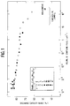
- Figure 1 shows the relationship between the volume of the compound phase (maximum volume) and the high rate discharge characteristics of the batteries.
- the abscissa represents the volume of the compound phase (maximum volume) and the vertical line represents the discharge capacity ratio at 4c discharge of the batteries compared to the discharge capacity at 0.2 C discharge.
- the hydrogen-absorbing alloys must be classified.
- the granules must be kneaded into a paste with a nickel powder, a conductive agent, and a powdered polytetrafluoroethylene (PTFE), a binder.
- PTFE powdered polytetrafluoroethylene
- a weight ratio of "hydrogen-absorbing alloy”:"conductive agent”:”binder” is set at 5:4:1.
- These mixtures are measured to obtain 5.0 grams of the hydrogen-absorbing alloy, and then wrapped by nickel mesh, a conductive substrate, whereby the hydrogen-absorbing alloy electrodes are produced.
- the hydrogen-absorbing alloy electrode as a negative electrode is combined with a sintered type nickel electrode to produce a battery with 1000 mAh capacity, and tested. In the batteries, 30% KOH is used as an alkaline electrolyte.
- samples of the hydrogen-absorbing alloys are prepared for the methods listed below.
- “Group A” represents the hydrogen-absorbing alloy produced by a high-frequency melting process after preparing an alloy ingot.
- Group B represents the hydrogen-absorbing alloy produced by an arc melting process after preparing an alloy ingot.
- Group C represents the hydrogen-absorbing alloy produced by an ultra quenching process after preparing an alloy ingot.
- Group D represents the hydrogen-absorbing alloy produced by a gas atomization process.
- Group E represents the hydrogen-absorbing alloy produced by a strip casting process. Conditions on the manufacturing methods of the various groups are shown in Table 1 and Table 2.
- Table 1 Melting Process Amount of produced alloy Group A high frequency melting 5kg Group B arc melting 50g Group C high frequency melting 5kg (on melting) 100g (on cooling) Group D high frequency melting 5kg Group E high frequency melting 5kg Table 2 Cooling Condition Cooling Speed (°C/sec) Group A Casting thickness of 10cm 500 - 2000 Group B Cooling a button shape bulk on a copper plate 500 - 2000 Group C Cooling on a water-cooled copper plate 3000 - 8000 Group D atomizing method 104 - 105 Group E single roll process 105 - 106
- the individual elements such as boron (B), carbon (C), titanium (Ti), vanadium (V), zirconium (Zr), niobium (Nb), molybdenum (Mo), tantalum (Ta) and tungsten (W), are used as additives for the samples as indicated in Table 3.
- Table 3 An element as an additive Manufacturing process Group A Group B Group C Group D Group E Boron (B) X X X X X Carbon (C) X X X X X Titanium (Ti) X X X Vanadium (V) X X X Zirconium (Zr) X X X X Niobium (Nb) X X Molybdenum (Mo) X X X X X Tantalum (Ta) X X Tungsten (W) X X X X Non-additive X
- the relationship between the volume of the compound phase (maximum volume) and the distance between two adjacent compound phases is researched.
- the "distance adjacent two of the compound phases" is decided by actually measuring the shortest distance between the compound phases under a microscope, where the cross sectional shape of the compound phase is approximated to an ellipse.
- Typical results are shown in FIG. 3. According to the results, the region in which the volume of the compound phase is less than 10 ⁇ m3 has the distance of less than the 100 ⁇ m. This territory has excellent high rate discharge characteristics. This result does not depend on the kinds of elements added to the hydrogen-absorbing alloy. The same results are observed in cases using boron (B), carbon (C), titanium (Ti), vanadium (V), zirconium (Zr), niobium (Nb), molybdenum (Mo), tantalum (Ta) and tungsten (W), respectively. Preparation of those alloys are carried out in the same manner as the first embodiment.
- the relationship between the cooling speed of melting compositions used to form the hydrogen-absorbing alloy and the volume of the compound phase (maximum volume) is examined.
- the cooling rate on manufacturing the hydrogen-absorbing alloy is changed according to samples prepared by above mentioned Group A, Group B, Group C, Group D and Group E.
- the ultra quenching process of Group C is completed by preparing a small amount, 10 g - 50 g, of the alloy, and then cooling and rapidly hardening it on a copper plate with a sufficiently large heat content as compared to the alloy.
- These alloys are prepared in the same way as the above mentioned first embodiment.
- the hydrogen-absorbing alloy in the third embodiment is represented by the formula MmNi 3.2 CoAl 0.2 Mn 0.6 X 0.1 .
- an additive "X” is an element selected a group of boron (B), carbon (C), titanium (Ti), vanadium (V), zirconium (Zr), niobium (Nb), molybdenum (Mo), tantalum (Ta) and tungsten (W).
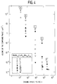
- FIG. 4 Typical results are shown in FIG. 4.
- the abscissa represents the cooling speed (°C/sec) for manufacturing the hydrogen-absorbing alloy and the vertical line represents the volume of the compound phase (maximum volume).
- the volume of the compound phase (maximum volume) largely depends upon the cooling speed. The result indicate that to obtain the volume for a compound phase of less than 10 ⁇ m3, the cooling speed should range from 103°C/sec to 106°C/sec.
- the cooling speed is not measured directly, but rather is inferred from the hardening speed of the composition. Nonetheless, the cooling speed does not differ from the theoretical value.
- the relationship between the concentration of the additive in the hydrogen-absorbing alloy of an element and the volume of the compound phase (maximum volume) is tested.
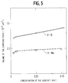
- the hydrogen-absorbing alloy used in the embodiment is represented by the formula MmNi 3.2 CoAl 0.2 Mn 0.6 X, wherein "X" is selected from boron (B) or molybdenum (Mo).
- the cooling speed for producing the alloy is set at 105°C/sec.
- FIG. 5 shows the relationship between the concentration of the additive "X" in the hydrogen-absorbing alloy and the volume of the compound phase (maximum volume). As shown in FIG. 5, there is no substantial change as to the volume of the compound phase ranging from 0.005 mol to 0.10 mol.
- FIG. 6 shows the relationship between the cooling speed for producing the alloy and the discharge capacity ratio.
Landscapes
- Chemical & Material Sciences (AREA)
- Chemical Kinetics & Catalysis (AREA)
- Electrochemistry (AREA)
- General Chemical & Material Sciences (AREA)
- Battery Electrode And Active Subsutance (AREA)
Abstract
Description
- This invention relates to a hydrogen-absorbing alloy used for a negative electrode in an alkaline storage battery.
- Alkaline storage batteries, such as Ni-Cd batteries, or lead acid batteries, are known. Currently, lighter and larger capacity batteries with high energy density are needed. Therefore, metal hydride storage batteries, which utilize a hydrogen-absorbing alloy to reversibly absorb and desorb hydrogen as a negative electrode, are attractive.
- The hydrogen-absorbing alloy for the negative electrode should be able to absorb and desorb reversibly at room temperature. An alloy satisfying this requirement is disclosed in the laid-open Japanese patent publication No.60-89066, wherein a hydrogen-absorbing alloy of an Mm-Ni type is described. The "Mm", a "Misch Metal", is a mixture of rare earth elements, such as lanthanum (La), cerium (Ce), neodymium (Nd) and praseodymium (Pr). These alloys have been used in practice.
- Electrochemical characteristics of the hydrogen-absorbing alloy electrode and the charge characteristics of an alkaline storage battery, that utilizes the hydrogen-absorbing alloy as a negative electrode, depend on various characteristics of the alloy used. Therefore, it is important to research and develop proper hydrogen-absorbing alloys for the electrode.
- For example, in a LaNi₅ alloy, an MmNi₅ alloy, partial replacements of lanthanum (La), "Mm" or nickel (Ni) by other elements improves the discharge capacity, temperature dependency and charge-discharge cycle life characteristics. Accordingly, such replacements are often researched and tested.
- When nickel (Ni) is partially replaced by cobalt (Co), copper (Cu) or another appropriate replacement, a change of volume in the alloy is controlled during charge-discharge cycles. As a result of this control, the alloy is prevented from flaking off of the electrode, and the charge-discharge cycle life of the battery is improved. Similarly, a partial replacement by manganese (Mn), aluminum (Al) or the like decreases the equilibrium-pressure of the hydrogen-absorbing alloy. Consequently, the amount of absorbed hydrogen is increased, as is the discharge capacity of the battery.
- Another method of decreasing the equilibrium-pressure in the hydrogen-absorbing alloy, with a composition MmBx, involves the reduction of the stoichiometric ratio "X" by an amount that element "B" is reduced. For example, the laid-open Japanese patent publication, No. 60-89066, describes a hydrogen-absorbing alloy, ABmCn, with a value of "m+n" in the range 4.8 to 5.4. Further, the laid-open Japanese patent publication No.2-277737 describes a hydrogen-absorbing alloy represented by formula ANiaCobMnc, wherein the value of "a+b+c" ranges from 3.85 to 4.78. These methods increase the amount of the absorbed hydrogen in the hydrogen-absorbing alloy.
- In manufacturing the hydrogen-absorbing alloy, each component of the alloy is measured and mixed in a fixed ratio, melted in an arc furnace with an inert argon atmosphere, and cooled in order to obtain hydrogen-absorbing alloy bulk. The alloys are then held in a vacuum furnace and heat treated at a high temperature (approximately 1000°C) for a fixed period of time. This "annealing" heat treatment causes homogenization of the hydrogen-absorbing alloys. For instance, the laid-open Japanese patent publication No.62-31947 describes an annealing treatment of the hydrogen-absorbing alloys within the temperature range of 950°C to 1250°C.
- To complete the electrode, the hydrogen-absorbing alloys are mechanically pulverized into granules having an average granule size of approximately 50 µm or less. The granules are then kneaded into a paste with powdered polytetrafluorethylene (PTFE), which acts as a binder and a conductive agent. The paste is coated onto a conductive substrate, such as a current collector, comprising a punched metal plate.
- Despite the use of various types of hydrogen-absorbing alloys or manufacturing methods used to prepare the alloys, it is difficult to improve the initial discharge characteristics of batteries employing hydrogen-absorbing electrodes. The laid-open Japanese patents, Nos.3-219036 and 3-280357, describe the use of a hydrogen-absorbing alloy as a negative electrode in an alkaline storage battery in which the alloy's main phase does not include boron (B), while a sub-phase includes boron (B). This method is advantageous in that the addition of boron (B) to the alloy, generates cracks at the first charge-discharge cycle of the battery. The area formed by the cracks is easily contacted with the alkaline electrolyte in the battery. As a result of contacting the electrolyte, the charge-discharge characteristics of the electrode improves relative to the first charge-discharge cycle.
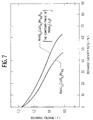
- The discharge characteristics of alkaline batteries, utilizing a hydrogen-absorbing alloy of formula MmNi3.2CoAl0.2Mn0.6B0.1 (referenced in the laid-open Japanese patent No.3-280357) and a hydrogen-absorbing alloy of formula MmNi3.2CoAl0.2Mn0.6 (used as a comparative example) have been tested. Figure 7, a graph of the discharge characteristics of the electrodes used as negative electrodes of the batteries, depicts the results of such testing. In FIG.7, the abscissa represents the discharge capacity ratio at 2 C discharge of the batteries and the vertical line represents the battery voltage. In the alloy MmNi3.2CoAl0.2Mn0.6B0.1, a subphase, with chemical formula MmNi₂CO₂B, is formed and observed. These tests demonstrate that the addition of boron (B) to the hydrogen-absorbing alloy prevents the deterioration of the discharge capacity and discharge voltage characteristics of the battery, even if the discharge current increases. In other words, adding boron (B) to the alloy improves the high rate discharge characteristics. The characteristics improve because adding boron (B) to the hydrogen-absorbing alloy generates cracks that form surfaces which easily contact with electrolytes. The contact with the electrolytes results in the improvement of electrode reactions.
- Nonetheless, this method is not without problems. At times, the degree of dispersion of the boron (B) is small in manufacturing the hydrogen-absorbing alloy and the boron (B) occasionally coheres in the hydrogen-absorbing alloy. Consequently, the results obtained by adding the boron (B) prove insufficient. This inventor has encountered such inferior results.
- The primary objective of the present invention is to improve the effects of additives, such as boron (B), in a hydrogen-absorbing alloy for a negative electrode.
- Another objective of the present invention is to provide a hydrogen-absorbing alloy for a negative electrode with increased discharge capacity from the initial charge-discharge cycle.
- A further objective of the present invention is to provide a hydrogen-absorbing alloy for a negative electrode with improved high rate discharge characteristics.
- The above objectives are fulfilled by a hydrogen-absorbing alloy for a negative electrode comprising a main texture of Mm-Ni system with a crystal structure of CaCu₅, and a plurality of compound phases with a crystal structure differing from the CaCu₅ type. Each of the compound phases are segregated in the main texture, wherein the volume of each of these compound phases is less than about 10 µm³.
- The above objectives may also be fulfilled by a method of manufacturing a hydrogen-absorbing alloy for a negative electrode comprising the following steps: melting compositions to be used to form a hydrogen-absorbing alloy of Mm-Ni system having a crystal structure of CaCu₅ type; and cooling the melted compositions at a rate ranging from about 10³°C/sec to about 10⁶°C/sec in order to generate a plurality of compound phases with a crystal structure differing from the CaCu₅ type and segregated in the CaCu₅ type crystal structure.
- Further, the above objectives may be fulfilled by a method of manufacturing a hydrogen-absorbing alloy for a negative electrode comprising the following steps: melting compositions to be used to form a hydrogen-absorbing alloy of an Mm-Ni system having a crystal structure of CaCu₅ type, wherein the compositions include cobalt (Co), nickel (Ni), and an element selected from a group of boron (B), carbon (C), tantalum (Ta), niobium (Nb), titanium (Ti), zirconium (Zr), molybdenum (Mo), tungsten (W) and bismuth (Bi); and cooling the melted compositions at a rate ranging from about 10³°C/sec in order to about 10⁶°C/sec to generate a plurality of compound phases having a crystal structure differing from a crystal structure of CaCu₅ type, segregated the crystal structure of CaCu₅ and having a volume of the compound phase less than about 10 µm³.
- In the hydrogen-absorbing alloy, the distance between two adjacent compound phases should be less than about 100 µm.
- Additionally, each of the compound phases should include an element selected from a group of boron (B), carbon (C), tantalum (Ta), niobium (Nb), titanium (Ti), zirconium (Zr), molybdenum (Mo), tungsten (W) and bismuth (Bi).
- Further, each of the compound phases may have a component selected from a group of Mm(Ni-Co)₄B, Mm(Ni-Co)C₂, Nb₅Ni, Ti₂(Ni-Co), Ti₃(Ni-Co)₄, Ti(Ni-Co), V(Ni-Co)₂, µ-Mo-Ni-Co, W, W(Ni-Co)₃ and Mm₂(Ni-X)₇, wherein "X" is an element selected from a member of cobalt (Co), iron (Fe), copper (Cu), silver (Ag), manganese (Mn) and aluminum (Al).
- These and other objectives, advantages and features of the invention will become apparent from the following description taken in conjunction with the accompanying drawings that illustrate specific embodiments of the invention. In the drawings:
- FIG. 1 is a graph depicting the relationship between the volume of the compound phase (maximum volume) and the discharge capacity ratio in the hydrogen-absorbing alloy, in accordance with the present invention;
- FIG. 2 is a cross-section of the hydrogen-absorbing alloy granule of the present invention;
- FIG. 3 is a graph depicting the relationship between the volume of the compound phase (maximum volume) and the distance between two adjacent compound phases of the present invention;
- FIG. 4 is a graph showing the relationship between the cooling speed of manufacturing hydrogen-absorbing alloys and the volume of the compound phase (maximum volume), of the present invention;
- FIG. 5 is a graph showing the relationship between the concentration of the additives used to generate the plurality of compound phases in the hydrogen-absorbing alloy and the volume of the compound phase (maximum phase), of the present invention;
- FIG. 6 is a graph showing the relationship between the cooling speed of manufacturing the hydrogen-absorbing alloy and the discharge capacity ratio of the present invention; and
- FIG. 7 is a graph showing the relationship between the discharge capacity and discharge voltage of the battery of a prior art.
- In the hydrogen-absorbing alloy for a negative electrode comprising a main texture of Mm-Ni system having a crystal structure of CaCu₅ type for an alkaline storage battery, it is difficult to maintain a homogeneous hydrogen-absorbing alloy when compound phases, in the main texture, having a crystal structure differing from a CaCu₅ type crystal structure segregate. In this state, hydrogen is desorbed and absorbed in the hydrogen-absorbing alloy caused by discharging and charging of the electrode, subsequently generating stress in the hydrogen-absorbing alloy granule. As a result, cracks generate between the compound phases and the main texture having a CaCu₅ type crystal structure. The new surface, generated by the cracks, easily contacts to an alkaline electrolyte and thereby improves the electrode characteristics. Unfortunately, because the new surface is gathered in small portions and the compound phases is not dispersed, the advantage created by the additives is not fully realized.
- In the present invention, the inventor succeeded in increasing the dispersion degree for a plurality of the compound phases, where the maximum volume of each of the compound phases is set less than 10 µm³. Further, the distance between two adjacent compound phases, is suitably set at less than about 100 µm.
- In this invention, each of the compound phases includes an element selected from a group of boron (B), carbon (C), tantalum (Ta), niobium (Nb), titanium (Ti), zirconium (Zr), molybdenum (Mo), tungsten (W) and bismuth (Bi).
- Further, each of the compound phases has a component selected from a group of Mm(Ni-Co)₄B, Mm(Ni-Co)C₂, Nb₅Ni, Ti₂(Ni-Co), Ti₃(Ni-Co)₄, Ti(Ni-Co), V(Ni-Co)₂, µ-Mo-Ni-Co, W, W(Ni-Co)₃ and Mm₂(Ni-X)₇, wherein "X" is an element selected from a member of cobalt (Co), iron (Fe), copper (Cu), silver (Ag), manganese (Mn) and aluminum (Al).
- In a first embodiment, after hydrogen-absorbing alloys are prepared, relationships between the compound phase in the alloys and high rate discharge characteristics are compared. The hydrogen-absorbing alloys used for the first embodiment primarily have a crystal structure of the CaCu₅ type and are represented by formulas of MmNi3.2CoAl0.2Mn0.6X0.1 and MmNi3.2CoAl0.2Mn0.6. In the former hydrogen-absorbing alloy, MmNi3.2CoAl0.2Mn0.6X0.1, a plurality of the compound phases having a crystal structure differing from a CaCu₅ type crystal structure is observed. In this formula "X" represents the element selected from the group of boron (B), carbon (C), titanium (Ti), vanadium (V), zirconium (Zr), niobium (Nb), molybdenum (Mo), tantalum (Ta) and tungsten (W). Figure 1 depicts the results of this test.
- In the present invention, the maximum volume of the compound phase is calculated as explained below. Observing a cross section of the hydrogen-absorbing alloy by EPMA (see FIG. 2), a maximum area, "S", of the compound phase in the cross section is measured. As a result, the volume of the compound phase is represented by the value of "S3/2". Figure 2 depicts a cross-section of the hydrogen-absorbing alloy granule represented by MmNi3.2CoAl0.2Mn0.6B0.1". In FIG.2, the small ovals, with hatched potions, contained within the larger circular structure represent a plurality of the compound phase of a formula of "MmNi₂CO₂B", which is distinguished from the main texture having a crystal structure of CaCu₅ type. The larger circular structure with hatched portions, represents the main texture having the crystal structure of CaCu₅ type as a main phase in the hydrogen-absorbing alloy.
- Figure 1 shows the relationship between the volume of the compound phase (maximum volume) and the high rate discharge characteristics of the batteries. In FIG. 1, the abscissa represents the volume of the compound phase (maximum volume) and the vertical line represents the discharge capacity ratio at 4c discharge of the batteries compared to the discharge capacity at 0.2 C discharge.
- To determine the relationship depicted in FIG. 1, the following experiment must be performed. First, the hydrogen-absorbing alloys must be classified. Next, the granules must be kneaded into a paste with a nickel powder, a conductive agent, and a powdered polytetrafluoroethylene (PTFE), a binder. In each paste, a weight ratio of "hydrogen-absorbing alloy":"conductive agent":"binder" is set at 5:4:1. These mixtures are measured to obtain 5.0 grams of the hydrogen-absorbing alloy, and then wrapped by nickel mesh, a conductive substrate, whereby the hydrogen-absorbing alloy electrodes are produced. Finally the hydrogen-absorbing alloy electrode as a negative electrode is combined with a sintered type nickel electrode to produce a battery with 1000 mAh capacity, and tested. In the batteries, 30% KOH is used as an alkaline electrolyte.
- As shown in FIG. 1, which depicts the results of these battery tests, when the volume exceeds approximately 10 µm³ of the compound phase, a decrease in the discharge capacity ratio in the batteries is observed. Therefore, when the volume of the compound phase (maximum volume) is less than about 10 µm³ in the hydrogen-absorbing alloy, excellent discharge characteristics of the batteries is obtained.
- In the embodiment, samples of the hydrogen-absorbing alloys are prepared for the methods listed below. "Group A" represents the hydrogen-absorbing alloy produced by a high-frequency melting process after preparing an alloy ingot. "Group B" represents the hydrogen-absorbing alloy produced by an arc melting process after preparing an alloy ingot. "Group C" represents the hydrogen-absorbing alloy produced by an ultra quenching process after preparing an alloy ingot. "Group D" represents the hydrogen-absorbing alloy produced by a gas atomization process. Finally "Group E" represents the hydrogen-absorbing alloy produced by a strip casting process. Conditions on the manufacturing methods of the various groups are shown in Table 1 and Table 2.
Table 1 Melting Process Amount of produced alloy Group A high frequency melting 5kg Group B arc melting 50g Group C high frequency melting 5kg (on melting) 100g (on cooling) Group D high frequency melting 5kg Group E high frequency melting 5kg Table 2 Cooling Condition Cooling Speed (°C/sec) Group A Casting thickness of 10cm 500 - 2000 Group B Cooling a button shape bulk on a copper plate 500 - 2000 Group C Cooling on a water-cooled copper plate 3000 - 8000 Group D atomizing method 10⁴ - 10⁵ Group E single roll process 10⁵ - 10⁶ - The individual elements, such as boron (B), carbon (C), titanium (Ti), vanadium (V), zirconium (Zr), niobium (Nb), molybdenum (Mo), tantalum (Ta) and tungsten (W), are used as additives for the samples as indicated in Table 3.
Table 3 An element as an additive Manufacturing process Group A Group B Group C Group D Group E Boron (B) X X X X X Carbon (C) X X X X Titanium (Ti) X X X Vanadium (V) X X X Zirconium (Zr) X X X X Niobium (Nb) X X Molybdenum (Mo) X X X X Tantalum (Ta) X X Tungsten (W) X X X Non-additive X - In a second embodiment, the relationship between the volume of the compound phase (maximum volume) and the distance between two adjacent compound phases is researched. In the research, the "distance adjacent two of the compound phases" is decided by actually measuring the shortest distance between the compound phases under a microscope, where the cross sectional shape of the compound phase is approximated to an ellipse.
- Typical results are shown in FIG. 3. According to the results, the region in which the volume of the compound phase is less than 10 µm³ has the distance of less than the 100 µm. This territory has excellent high rate discharge characteristics. This result does not depend on the kinds of elements added to the hydrogen-absorbing alloy. The same results are observed in cases using boron (B), carbon (C), titanium (Ti), vanadium (V), zirconium (Zr), niobium (Nb), molybdenum (Mo), tantalum (Ta) and tungsten (W), respectively. Preparation of those alloys are carried out in the same manner as the first embodiment.
- In a third embodiment, the relationship between the cooling speed of melting compositions used to form the hydrogen-absorbing alloy and the volume of the compound phase (maximum volume) is examined. The cooling rate on manufacturing the hydrogen-absorbing alloy is changed according to samples prepared by above mentioned Group A, Group B, Group C, Group D and Group E. The ultra quenching process of Group C is completed by preparing a small amount, 10 g - 50 g, of the alloy, and then cooling and rapidly hardening it on a copper plate with a sufficiently large heat content as compared to the alloy. These alloys are prepared in the same way as the above mentioned first embodiment. The hydrogen-absorbing alloy in the third embodiment is represented by the formula MmNi3.2CoAl0.2Mn0.6X0.1. In this formula an additive "X" is an element selected a group of boron (B), carbon (C), titanium (Ti), vanadium (V), zirconium (Zr), niobium (Nb), molybdenum (Mo), tantalum (Ta) and tungsten (W).
- Typical results are shown in FIG. 4. In FIG. 4, the abscissa represents the cooling speed (°C/sec) for manufacturing the hydrogen-absorbing alloy and the vertical line represents the volume of the compound phase (maximum volume). According to the results, the volume of the compound phase (maximum volume) largely depends upon the cooling speed. The result indicate that to obtain the volume for a compound phase of less than 10 µm³, the cooling speed should range from 10³°C/sec to 10⁶°C/sec.
- In this embodiment, the cooling speed is not measured directly, but rather is inferred from the hardening speed of the composition. Nonetheless, the cooling speed does not differ from the theoretical value.
- In a fourth embodiment, the relationship between the concentration of the additive in the hydrogen-absorbing alloy of an element and the volume of the compound phase (maximum volume) is tested. The hydrogen-absorbing alloy used in the embodiment is represented by the formula MmNi3.2CoAl0.2Mn0.6X, wherein "X" is selected from boron (B) or molybdenum (Mo). The cooling speed for producing the alloy is set at 10⁵°C/sec.
- Typical results are shown in FIG. 5. Figure 5 shows the relationship between the concentration of the additive "X" in the hydrogen-absorbing alloy and the volume of the compound phase (maximum volume). As shown in FIG. 5, there is no substantial change as to the volume of the compound phase ranging from 0.005 mol to 0.10 mol.
- In a fifth embodiment, the relationship between the cooling speed of the alloy and the discharge capacity ratio at 4 C compared to 2 C discharge is researched. In this embodiment, "X" is boron (B) and the amount added to the hydrogen-absorbing alloy is changed. Further, the hydrogen-absorbing alloy is represented by the formula MmNi3.2CoAl0.2Mn0.6By, wherein the "y" value is set at "0.1", "0.005" and "0", respectively.
- Typical results are shown in FIG. 6. Figure 6 shows the relationship between the cooling speed for producing the alloy and the discharge capacity ratio.
- According to FIG. 6, for cooling rates exceeding about 10³°C/sec, an improvement of the discharge characteristics of the electrode is observed, even if the amount of the additive element "X" is set at 0.1 mol or 0.005 mol.
Claims (12)
- A hydrogen-absorbing alloy for a negative electrode comprising:
a main texture of Mm-Ni system having a crystal structure of CaCu₅ type; and
a plurality of compound phases having a crystal structure differing form the crystal structure of CaCu₅ type, where each of the compound phases are segregated in the main texture, and wherein the volume of each of the compound phases is less than about 10 µm³. - A hydrogen-absorbing alloy for a negative electrode according to claim 1, wherein a distance between two adjacent compound phases is less than about 100 µm.
- A hydrogen-absorbing alloy for a negative electrode according to claim 1, wherein each of the compound phases includes an element selected from a group of boron (B), carbon (C), tantalum (Ta), niobium (Nb), titanium (Ti), zirconium (Zr), molybdenum (Mo), tungsten (W) and bismuth (Bi).
- A hydrogen-absorbing alloy for a negative electrode according to claim 1, wherein each of said compound phases has a component selected from a group of Mm(Ni-Co)₄B, Mm(Ni-Co)C₂, Nb₅Ni, Ti₂(Ni-Co), Ti₃(Ni-Co)₄, Ti(Ni-Co), V(Ni-Co)₂, µ-Mo-Ni-Co, W, W(Ni-Co)₃ and Mm₂(Ni-X)₇, wherein "X" is an element selected from a member of cobalt (Co), iron (Fe), copper (Cu), silver (Ag), manganese (Mn) and aluminum (Al).
- A method of manufacturing a hydrogen-absorbing alloy for a negative electrode comprising the steps of:
melting compositions to be used to form a hydrogen-absorbing alloy of an Mm-Ni system having a crystal structure of CaCu₅ type; and
cooling the melted compositions at a cooling speed ranging from about 10³°C/sec to about 10⁶°C/sec in order to generate a plurality of compound phases having a crystal structure other than the crystal structure of CaCu₅ type, and segregated in the crystal structure of CaCu₅ type. - A method of manufacturing hydrogen-absorbing alloy for a negative electrode according to claim 5, wherein a volume of each of said compound phases is less than about 10 µm³.
- A method of manufacturing hydrogen-absorbing alloy for a negative electrode according to claim 5, wherein the distance between two adjacent compound phases is less than about 100 µm.
- A method of manufacturing hydrogen-absorbing alloy for a negative electrode according to claim 5, wherein each of the compound phases includes an element selected from a group of boron (B), carbon (C), tantalum (Ta), niobium (Nb), titanium (Ti), zirconium (Zr), molybdenum (Mo), tungsten (W) and bismuth (Bi).
- A method of manufacturing hydrogen-absorbing alloy for a negative electrode according to claim 5, wherein each of the compound phases has a component selected from a group of Mm(Ni-Co)₄B, Mm(Ni-Co)C₂, Nb₅Ni, Ti₂(Ni-Co), Ti₃(Ni-Co)₄, Ti(Ni-Co), V(Ni-Co)₂, µ-Mo-Ni-Co, W, W(Ni-Co)₃ and Mm₂(Ni-X)₇, wherein "X" is an element selected from a member of cobalt (Co), iron (Fe), copper (Cu), silver (Ag), manganese (Mn) and aluminum (Al).
- A method of manufacturing a hydrogen-absorbing alloy for a negative electrode comprising the steps of:
melting compositions to be used to form a hydrogen-absorbing alloy of Mm-Ni system having a crystal structure of CaCu₅ type, said compositions including cobalt (Co), nickel (Ni) and an element selected from a group of boron (B), carbon (C), tantalum (Ta), niobium (Nb), titanium (Ti), zirconium (Zr), molybdenum (Mo), tungsten (W) and bismuth (Bi); and
cooling said melted compositions at a cooling speed ranging from about 10³°C/sec to about 10⁶°C/sec in order to generate a plurality of compound phases having a crystal structure other than the crystal structure of CaCu₅ type and segregated in the crystal structure of CaCu₅, where the volume of the compound phase is less than about 10 µm³. - A method of manufacturing hydrogen-absorbing alloy for a negative electrode according to claim 10, wherein a distance between two adjacent compound phases is less than about 100 µm.
- A method of manufacturing hydrogen-absorbing alloy for a negative electrode according to claim 10, wherein each of the compound phases has a component selected from a group of Mm(Ni-Co)₄B, Mm(Ni-Co)C₂, Nb₅Ni, Ti₂(Ni-Co), Ti₃(Ni-Co)₄, Ti(Ni-Co), V(Ni-Co)₂, µ-Mo-Ni-Co, W, W(Ni-Co)₃ and Mm₂(Ni-X)₇, wherein "X" is an element selected from a member of cobalt (Co), iron (Fe), copper (Cu), silver (Ag), manganese (Mn) and aluminum (Al).
Applications Claiming Priority (2)
| Application Number | Priority Date | Filing Date | Title |
|---|---|---|---|
| US14382 | 1993-02-05 | ||
| US08/014,382 US5376474A (en) | 1993-02-05 | 1993-02-05 | Hydrogen-absorbing alloy for a negative electrode and manufacturing method therefor |
Publications (3)
| Publication Number | Publication Date |
|---|---|
| EP0609609A2 true EP0609609A2 (en) | 1994-08-10 |
| EP0609609A3 EP0609609A3 (en) | 1994-08-31 |
| EP0609609B1 EP0609609B1 (en) | 1998-03-04 |
Family
ID=21765138
Family Applications (1)
| Application Number | Title | Priority Date | Filing Date |
|---|---|---|---|
| EP93307911A Expired - Lifetime EP0609609B1 (en) | 1993-02-05 | 1993-10-05 | Method for manufacturing a hydrogen-absorbing alloy for a negative electrode |
Country Status (4)
| Country | Link |
|---|---|
| US (1) | US5376474A (en) |
| EP (1) | EP0609609B1 (en) |
| JP (1) | JP3432873B2 (en) |
| DE (1) | DE69317252T2 (en) |
Cited By (6)
| Publication number | Priority date | Publication date | Assignee | Title |
|---|---|---|---|---|
| WO1996028579A1 (en) * | 1995-03-09 | 1996-09-19 | Mitsubishi Materials Corporation | Hydrogen occluding alloy and electrode made of the alloy |
| EP0736918A1 (en) * | 1995-04-04 | 1996-10-09 | Dai Nippon Printing Co., Ltd. | Electrode for secondary battery with nonaqueous electrolyte and process for producing the same |
| EP0756343A1 (en) * | 1995-07-27 | 1997-01-29 | VARTA Batterie Aktiengesellschaft | Alloys for use as active material for the negative electrode of an alkaline,rechargeable, nickel metal-hybride battery and its method of preparation |
| US5885378A (en) * | 1995-07-12 | 1999-03-23 | Mitsubishi Materials Corporation | Hydrogen occluding alloy and electrode made of the alloy |
| US5951945A (en) * | 1995-06-13 | 1999-09-14 | Mitsubishi Materials Corporation | Hydrogen occluding alloy and electrode made of the alloy |
| EP1113513A2 (en) * | 1999-12-24 | 2001-07-04 | Mitsubishi Materials Corporation | Hydrogen occluding alloy for battery cathode |
Families Citing this family (12)
| Publication number | Priority date | Publication date | Assignee | Title |
|---|---|---|---|---|
| EP0560535B1 (en) * | 1992-03-05 | 1999-11-03 | Sanyo Electric Co., Limited. | Hydrogen-absorbing alloy for negative electrode |
| US5547784A (en) * | 1993-01-18 | 1996-08-20 | Matsushita Electric Industrial Co., Ltd. | Alkaline storage battery and method for producing the same |
| JPH0790435A (en) * | 1993-09-20 | 1995-04-04 | Shin Etsu Chem Co Ltd | Hydrogen storage alloy, its manufacture and electrode using this alloy |
| US5512385A (en) * | 1994-02-28 | 1996-04-30 | Matsushita Electric Industrial Co., Ltd. | Hydrogen storage alloy and nickel-metal hydride storage battery using the same |
| DE4426958A1 (en) * | 1994-07-29 | 1996-02-01 | Varta Batterie | Gas-tight sealed metal oxide-metal hydride accumulator |
| US5629000A (en) * | 1994-11-25 | 1997-05-13 | Sanyo Electric Co., Ltd. | Hydrogen-absorbing alloy electrode for metal hydride alkaline batteries and process for producing the same |
| JPH08244295A (en) * | 1995-03-14 | 1996-09-24 | Asahi Optical Co Ltd | Thermal printer and using method therefor |
| JP3214341B2 (en) * | 1996-03-08 | 2001-10-02 | 松下電器産業株式会社 | Manufacturing method of hydrogen storage alloy for batteries |
| US6074783A (en) * | 1996-12-19 | 2000-06-13 | Duracell Inc. | Hydrogen storage alloys for use in rechargeable electrochemical cells, and methods of producing them |
| EP0867957B1 (en) * | 1997-03-28 | 2008-05-14 | Matsushita Electric Industrial Co., Ltd. | Negative electrode for alkaline storage batteries |
| JP2001135311A (en) * | 1999-11-04 | 2001-05-18 | Matsushita Electric Ind Co Ltd | Alkaline storage battery |
| WO2004027901A2 (en) * | 2002-09-17 | 2004-04-01 | Diffusion Science, Inc. | Electrochemical generation, storage and reaction of hydrogen and oxygen using gas permeable catalyst-coated hollow microspheres |
Citations (7)
| Publication number | Priority date | Publication date | Assignee | Title |
|---|---|---|---|---|
| JPH02228434A (en) * | 1989-03-01 | 1990-09-11 | Sanyo Electric Co Ltd | Manufacture of hydrogen storage alloy |
| EP0417802A1 (en) * | 1989-09-13 | 1991-03-20 | Canon Kabushiki Kaisha | Hydrogen storage body |
| JPH0393159A (en) * | 1989-09-05 | 1991-04-18 | Sanyo Electric Co Ltd | Hydrogen storage alloy |
| JPH0393158A (en) * | 1989-09-01 | 1991-04-18 | Sanyo Electric Co Ltd | Hydrogen storage alloy electrode |
| JPH03219036A (en) * | 1990-01-22 | 1991-09-26 | Sanyo Electric Co Ltd | Hydrogen storage alloy electrode for alkaline storage battery |
| JPH03280357A (en) * | 1990-03-28 | 1991-12-11 | Sanyo Electric Co Ltd | Electrode of hydrogen storage alloy for alkaline storage battery |
| US5135589A (en) * | 1990-04-16 | 1992-08-04 | Fetcenko Michael A | Metastable hydrogen storage alloy material |
Family Cites Families (6)
| Publication number | Priority date | Publication date | Assignee | Title |
|---|---|---|---|---|
| US3824131A (en) * | 1970-04-24 | 1974-07-16 | K Beccu | Negative electrode of titanium-nickel alloy hydride phases |
| US4623597A (en) * | 1982-04-28 | 1986-11-18 | Energy Conversion Devices, Inc. | Rechargeable battery and electrode used therein |
| NL8303630A (en) * | 1983-10-21 | 1985-05-17 | Philips Nv | ELECTROCHEMICAL CELL WITH STABLE HYDRIDE-FORMING MATERIALS. |
| JP2926734B2 (en) * | 1989-02-23 | 1999-07-28 | 松下電器産業株式会社 | Alkaline storage battery using hydrogen storage alloy |
| NL8901776A (en) * | 1989-07-11 | 1991-02-01 | Philips Nv | ELECTROCHEMICAL CELL. |
| JP2972919B2 (en) * | 1990-09-18 | 1999-11-08 | 日本電池株式会社 | Method for producing hydrogen storage alloy powder for storage battery and hydrogen storage electrode |
-
1993
- 1993-02-05 US US08/014,382 patent/US5376474A/en not_active Expired - Lifetime
- 1993-10-05 EP EP93307911A patent/EP0609609B1/en not_active Expired - Lifetime
- 1993-10-05 DE DE69317252T patent/DE69317252T2/en not_active Expired - Fee Related
- 1993-12-15 JP JP31519493A patent/JP3432873B2/en not_active Expired - Fee Related
Patent Citations (7)
| Publication number | Priority date | Publication date | Assignee | Title |
|---|---|---|---|---|
| JPH02228434A (en) * | 1989-03-01 | 1990-09-11 | Sanyo Electric Co Ltd | Manufacture of hydrogen storage alloy |
| JPH0393158A (en) * | 1989-09-01 | 1991-04-18 | Sanyo Electric Co Ltd | Hydrogen storage alloy electrode |
| JPH0393159A (en) * | 1989-09-05 | 1991-04-18 | Sanyo Electric Co Ltd | Hydrogen storage alloy |
| EP0417802A1 (en) * | 1989-09-13 | 1991-03-20 | Canon Kabushiki Kaisha | Hydrogen storage body |
| JPH03219036A (en) * | 1990-01-22 | 1991-09-26 | Sanyo Electric Co Ltd | Hydrogen storage alloy electrode for alkaline storage battery |
| JPH03280357A (en) * | 1990-03-28 | 1991-12-11 | Sanyo Electric Co Ltd | Electrode of hydrogen storage alloy for alkaline storage battery |
| US5135589A (en) * | 1990-04-16 | 1992-08-04 | Fetcenko Michael A | Metastable hydrogen storage alloy material |
Non-Patent Citations (5)
| Title |
|---|
| DATABASE WPI 1990 Derwent Publications Ltd., London, GB; AN 318006 & JP-A-2 228 434 (SANYO ELECTRIC K.K.) 11 September 1990 * |
| PATENT ABSTRACTS OF JAPAN vol. 15, no. 273 (E-1088)11 July 1991 & JP-A-03 093 158 (SANYO ELECTRIC CO LTD) 18 April 1991 * |
| PATENT ABSTRACTS OF JAPAN vol. 15, no. 273 (E-1088)11 July 1991 & JP-A-03 093 159 (SANYO ELECTRIC CO LTD) 18 April 1991 * |
| PATENT ABSTRACTS OF JAPAN vol. 15, no. 500 (C-0895)18 December 1991 & JP-A-03 219 036 (SANYO ELECTRIC CO LTD) 26 September 1991 * |
| PATENT ABSTRACTS OF JAPAN vol. 16, no. 101 (E-1177)12 March 1992 & JP-A-03 280 357 (SANYO ELECTRIC CO LTD) 11 December 1991 * |
Cited By (8)
| Publication number | Priority date | Publication date | Assignee | Title |
|---|---|---|---|---|
| WO1996028579A1 (en) * | 1995-03-09 | 1996-09-19 | Mitsubishi Materials Corporation | Hydrogen occluding alloy and electrode made of the alloy |
| EP0736918A1 (en) * | 1995-04-04 | 1996-10-09 | Dai Nippon Printing Co., Ltd. | Electrode for secondary battery with nonaqueous electrolyte and process for producing the same |
| US5951945A (en) * | 1995-06-13 | 1999-09-14 | Mitsubishi Materials Corporation | Hydrogen occluding alloy and electrode made of the alloy |
| US5885378A (en) * | 1995-07-12 | 1999-03-23 | Mitsubishi Materials Corporation | Hydrogen occluding alloy and electrode made of the alloy |
| EP0756343A1 (en) * | 1995-07-27 | 1997-01-29 | VARTA Batterie Aktiengesellschaft | Alloys for use as active material for the negative electrode of an alkaline,rechargeable, nickel metal-hybride battery and its method of preparation |
| US5738958A (en) * | 1995-07-27 | 1998-04-14 | Varta Batterie Aktiengesellschaft | Alloys for use as active material for the negative electrode of an alkaline, rechargeable nickel-metal hydride battery, and process for its production |
| EP1113513A2 (en) * | 1999-12-24 | 2001-07-04 | Mitsubishi Materials Corporation | Hydrogen occluding alloy for battery cathode |
| EP1113513A3 (en) * | 1999-12-24 | 2001-11-28 | Mitsubishi Materials Corporation | Hydrogen occluding alloy for battery cathode |
Also Published As
| Publication number | Publication date |
|---|---|
| DE69317252T2 (en) | 1998-08-27 |
| EP0609609B1 (en) | 1998-03-04 |
| EP0609609A3 (en) | 1994-08-31 |
| JPH06231763A (en) | 1994-08-19 |
| US5376474A (en) | 1994-12-27 |
| DE69317252D1 (en) | 1998-04-09 |
| JP3432873B2 (en) | 2003-08-04 |
Similar Documents
| Publication | Publication Date | Title |
|---|---|---|
| EP0609609B1 (en) | Method for manufacturing a hydrogen-absorbing alloy for a negative electrode | |
| JPH10294112A (en) | Lithium secondary battery | |
| EP0867956B1 (en) | Hydrogen storage alloy electrode | |
| KR100355049B1 (en) | Alkali Metal Oxide / Metal Hydride Batteries | |
| US5753386A (en) | Hydrogen-absorbing alloy for battery and secondary nickel-metal hydride battery | |
| EP1075032B1 (en) | Hydrogen absorbing alloy and nickel-metal hydride rechargeable battery | |
| EP0550153B1 (en) | Hydrogen-absorbing alloy electrode and its manufacturing method | |
| US6472102B2 (en) | Hydridable alloy | |
| JP2983426B2 (en) | Production method and electrode for hydrogen storage alloy | |
| JPH08120364A (en) | Hydrogen storage alloy for battery, its production and nickel-hydrogen secondary battery | |
| JPH0949034A (en) | Production of hydrogen storage alloy | |
| JP3410308B2 (en) | Hydrogen storage alloy and nickel-hydrogen battery electrode using the same | |
| JP3301792B2 (en) | Hydrogen storage alloy electrode | |
| JP2680566B2 (en) | Hydrogen storage electrode | |
| JP3322452B2 (en) | Rare earth hydrogen storage alloy for alkaline storage batteries | |
| JP3470987B2 (en) | Hydrogen storage alloy and hydrogen storage alloy electrode | |
| JP3432866B2 (en) | Hydrogen storage alloy electrodes for alkaline storage batteries | |
| JP2000243388A (en) | Hydrogen storage alloy electrode, manufacture of electrode and alkaline storage battery | |
| JP3258728B2 (en) | Hydrogen storage alloy electrode for metal / hydride secondary batteries | |
| JP3255007B2 (en) | Hydrogen storage alloy for batteries and method for producing the same | |
| JP3816138B6 (en) | Metal oxide-metal hydride alkaline battery and method for producing hydrogen storage alloy negative electrode for the battery | |
| JPH04187735A (en) | Hydrogen storage alloy electrode | |
| JP2983425B2 (en) | Production method and electrode for hydrogen storage alloy | |
| JPH08287908A (en) | Hydrogen storage alloy electrode | |
| JPH08319529A (en) | Hydrogen storage alloy and hydrogen storage alloy electrode |
Legal Events
| Date | Code | Title | Description |
|---|---|---|---|
| PUAI | Public reference made under article 153(3) epc to a published international application that has entered the european phase |
Free format text: ORIGINAL CODE: 0009012 |
|
| PUAL | Search report despatched |
Free format text: ORIGINAL CODE: 0009013 |
|
| AK | Designated contracting states |
Kind code of ref document: A2 Designated state(s): DE FR |
|
| AK | Designated contracting states |
Kind code of ref document: A3 Designated state(s): DE FR |
|
| 17P | Request for examination filed |
Effective date: 19941031 |
|
| 17Q | First examination report despatched |
Effective date: 19950607 |
|
| GRAG | Despatch of communication of intention to grant |
Free format text: ORIGINAL CODE: EPIDOS AGRA |
|
| GRAG | Despatch of communication of intention to grant |
Free format text: ORIGINAL CODE: EPIDOS AGRA |
|
| GRAH | Despatch of communication of intention to grant a patent |
Free format text: ORIGINAL CODE: EPIDOS IGRA |
|
| GRAH | Despatch of communication of intention to grant a patent |
Free format text: ORIGINAL CODE: EPIDOS IGRA |
|
| GRAA | (expected) grant |
Free format text: ORIGINAL CODE: 0009210 |
|
| AK | Designated contracting states |
Kind code of ref document: B1 Designated state(s): DE FR |
|
| REF | Corresponds to: |
Ref document number: 69317252 Country of ref document: DE Date of ref document: 19980409 |
|
| ET | Fr: translation filed | ||
| PLBE | No opposition filed within time limit |
Free format text: ORIGINAL CODE: 0009261 |
|
| STAA | Information on the status of an ep patent application or granted ep patent |
Free format text: STATUS: NO OPPOSITION FILED WITHIN TIME LIMIT |
|
| 26N | No opposition filed | ||
| PGFP | Annual fee paid to national office [announced via postgrant information from national office to epo] |
Ref country code: DE Payment date: 20070927 Year of fee payment: 15 |
|
| PGFP | Annual fee paid to national office [announced via postgrant information from national office to epo] |
Ref country code: FR Payment date: 20071009 Year of fee payment: 15 |
|
| REG | Reference to a national code |
Ref country code: FR Ref legal event code: ST Effective date: 20090630 |
|
| PG25 | Lapsed in a contracting state [announced via postgrant information from national office to epo] |
Ref country code: DE Free format text: LAPSE BECAUSE OF NON-PAYMENT OF DUE FEES Effective date: 20090501 |
|
| PG25 | Lapsed in a contracting state [announced via postgrant information from national office to epo] |
Ref country code: FR Free format text: LAPSE BECAUSE OF NON-PAYMENT OF DUE FEES Effective date: 20081031 |