EP0609262B1 - Actuator and hood for dispensing device - Google Patents
Actuator and hood for dispensing device Download PDFInfo
- Publication number
- EP0609262B1 EP0609262B1 EP92920740A EP92920740A EP0609262B1 EP 0609262 B1 EP0609262 B1 EP 0609262B1 EP 92920740 A EP92920740 A EP 92920740A EP 92920740 A EP92920740 A EP 92920740A EP 0609262 B1 EP0609262 B1 EP 0609262B1
- Authority
- EP
- European Patent Office
- Prior art keywords
- actuator
- hood
- outlet
- opening
- container
- Prior art date
- Legal status (The legal status is an assumption and is not a legal conclusion. Google has not performed a legal analysis and makes no representation as to the accuracy of the status listed.)
- Expired - Lifetime
Links
- 238000005187 foaming Methods 0.000 claims abstract description 10
- 239000000463 material Substances 0.000 claims description 23
- 239000000126 substance Substances 0.000 claims description 12
- 239000006260 foam Substances 0.000 abstract description 8
- 238000001035 drying Methods 0.000 description 5
- 239000006261 foam material Substances 0.000 description 2
- 239000000443 aerosol Substances 0.000 description 1
- 230000015572 biosynthetic process Effects 0.000 description 1
- 230000005484 gravity Effects 0.000 description 1
- 238000004519 manufacturing process Methods 0.000 description 1
- 230000000717 retained effect Effects 0.000 description 1
- 239000007921 spray Substances 0.000 description 1
Images


Classifications
-
- B—PERFORMING OPERATIONS; TRANSPORTING
- B65—CONVEYING; PACKING; STORING; HANDLING THIN OR FILAMENTARY MATERIAL
- B65D—CONTAINERS FOR STORAGE OR TRANSPORT OF ARTICLES OR MATERIALS, e.g. BAGS, BARRELS, BOTTLES, BOXES, CANS, CARTONS, CRATES, DRUMS, JARS, TANKS, HOPPERS, FORWARDING CONTAINERS; ACCESSORIES, CLOSURES, OR FITTINGS THEREFOR; PACKAGING ELEMENTS; PACKAGES
- B65D83/00—Containers or packages with special means for dispensing contents
- B65D83/14—Containers for dispensing liquid or semi-liquid contents by internal gaseous pressure, i.e. aerosol containers comprising propellant
- B65D83/40—Closure caps
-
- B—PERFORMING OPERATIONS; TRANSPORTING
- B05—SPRAYING OR ATOMISING IN GENERAL; APPLYING FLUENT MATERIALS TO SURFACES, IN GENERAL
- B05B—SPRAYING APPARATUS; ATOMISING APPARATUS; NOZZLES
- B05B7/00—Spraying apparatus for discharge of liquids or other fluent materials from two or more sources, e.g. of liquid and air, of powder and gas
- B05B7/0018—Spraying apparatus for discharge of liquids or other fluent materials from two or more sources, e.g. of liquid and air, of powder and gas with devices for making foam
- B05B7/0025—Spraying apparatus for discharge of liquids or other fluent materials from two or more sources, e.g. of liquid and air, of powder and gas with devices for making foam with a compressed gas supply
-
- B—PERFORMING OPERATIONS; TRANSPORTING
- B65—CONVEYING; PACKING; STORING; HANDLING THIN OR FILAMENTARY MATERIAL
- B65D—CONTAINERS FOR STORAGE OR TRANSPORT OF ARTICLES OR MATERIALS, e.g. BAGS, BARRELS, BOTTLES, BOXES, CANS, CARTONS, CRATES, DRUMS, JARS, TANKS, HOPPERS, FORWARDING CONTAINERS; ACCESSORIES, CLOSURES, OR FITTINGS THEREFOR; PACKAGING ELEMENTS; PACKAGES
- B65D83/00—Containers or packages with special means for dispensing contents
- B65D83/14—Containers for dispensing liquid or semi-liquid contents by internal gaseous pressure, i.e. aerosol containers comprising propellant
- B65D83/16—Actuating means
- B65D83/20—Actuator caps
Definitions
- the present invention is directed to apparatus for dispensing a foaming product contained in a pressurized container and more particularly to an actuator and hood for such dispensing device.
- a great many products may be found on the market which provide a shaving foam dispensed from a pressurized container of the type having a valve which includes a valve operating stem extending from the container top the stem having a free end which is moveable downwardly to release pressurized material through an opening in the valve stem.
- these containers are provided with a hand operated actuator and a cap or hood which sealingly engages the top of the container, covering the actuator, when the shaving product is stored and not in use.
- a gel substance as a shaving material, the substance being formed as a gel as it is dispensed, but producing a foam when applied to the skin of the user.
- Prior art reference U.S. Patent 4,978,035 discloses for a container with foamable substance released by moving a valve stem or the top of the container, an apparatus including an actuator having a first portion attachable to the container top and a second portion with a conduit for dispensing the foamed substance from the operating stem.
- the conduit has an outlet at one end thereof and a wall defining an inlet opening for receiving a portion of the operating stem.
- the wall has an inwardly projecting surface for engaging the free end of the valve stem.
- the actuator further includes an elongated nozzle extending outwardly from the center line of the container and terminates in a substantially planar surface in which the outlet is formed.
- GB-A-1057353 discloses a cap for a pressurized aerosol dispensing container.
- the cap includes a closure cap fitted on the top of the container to enclose a dispensing spray valve, a lever with the closure cap for actuating the valve, a first aperture in a side wall of the closure cap through which contents of the container are dispensed, and a second aperture in the side wall diametrically opposite the first aperture to allow access to the lever.
- the foamable material over a period of time generally extends from the nozzle to the inner surface of the cap or hood, at which point it contacts the surface, remains moist, and due to a lack of drying environment, continues to foam and spreads along the inner surface of the hood which is sealingly engaged to the container.
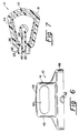
- FIG. 1 there is shown apparatus of the prior art for dispensing a foaming product contained in a pressurized container C of the type alluded to above, having a valve stem extending from the container top terminating in a free end which is interconnected to an actuator A having a nozzle N with an outlet opening through which the material, whether a directly produced foam or gel, is dispensed.
- the dispensing apparatus further comprises a cap or hood H which is sealingly engaged to the container C at its rim R when the product is not being used.
- the dispensing apparatus 10 constructed in accordance with the teaching of the present invention.
- the dispensing apparatus 10 comprises an actuator 12 and a hood 14, the hood being removeable during usage of the dispensing device as shown in Figure 3, and serving to cover the actuator 12 by being sealingly engaged to the structure forming the actuator 12 as shown in Figure 2.
- the dispensing apparatus 10 is mounted on a pressurized container 16 of the type having a valve including a valve operating stem extending from the container top upwardly and having a free end which is moveable downwardly to release pressurized material, which in the present embodiment is in the form of a foaming gel, through an opening in the free end of the valve stem.
- pressurized container 16 of the type having a valve including a valve operating stem extending from the container top upwardly and having a free end which is moveable downwardly to release pressurized material, which in the present embodiment is in the form of a foaming gel, through an opening in the free end of the valve stem.
- Such containers are well known in the art and therefore will
- the actuator 12 comprises a first portion 18 having an outer cylindrical wall 20 and an inner cylindrical wall 22 having a lip 23 and extending downwardly into the opening provided by the outer cylindrical wall 20.
- the actuator portion 18 is constructed such that the inner cylindrical wall 22 may be force fit over a valve crimp 25 formed at the top of the pressurized container 16 with the lip 23 under the valve crimp and the upwardly extending valve 27 engaged in a second actuator portion 24 as will be explained in detail below.
- the actuator portion 18 when assembled to the container 16 is prevented from being forced downwardly to a position which would activate the valve 27 by virtue of four downwardly extending flanges 29 (only two shown) contacting the valve crimp 25.
- the actuator portion 24 is freely moveable relative to the actuator portion 18 by virtue of a resilient hinge 26 formed between the two actuator portions 18 and 24.
- the actuator portion 24 has formed therein a conduit 28 having an outlet opening 30 at one end thereof and wall structure defining an inlet opening 32 for receiving a portion of the valve stem.
- the wall structure has an inwardly projecting surface 34 for engaging the end of the valve stem without forcing the valve stem downwardly when the actuator portion 18 is fixed to the pressurized container 16 as described above.
- the vertical walls 36 of the actuator portion 24 are substantially rigid and the upper surface of the actuator portion has a plurality of laterally extending ribs 38 to provide a surface by which the user may force the actuator portion 24 downwardly, rotating about the hinge 26, to force the valve stem down and release material into the conduit 28.
- the outlet 30 terminates in a nozzle portion 33 of the actuator 12 which has an outwardly extending flange disposed about the outlet.
- the outlet 30 is set inwardly of the edge of the flange 42 and formed in a planar surface 40.
- the surface 40 and flange 42 form the nozzle portion 33 for dispensing the foaming gel material.
- the flange 42 terminates below and to either side of the outlet opening 30 creating a notch 35 which substantially provides a continuation of the surface 40 and allows material forced from the outlet opening 30 to gradually move down the surface without being retained within the nozzle, as best shown in Figure 2.
- the hood 14 is cylindrical in form and shown to comprise a closed top wall 45, side wall 46 and an open bottom formed by a rim 48.
- An elongated opening 50 is formed in the side wall 46 and sized to allow the gas initially entrained in the foam product to vent uninhibited from the hood 14 when the hood is placed over the actuator. It has been found that the opening 50 is best utilized when located adjacent the planar surface 40 containing the outlet opening 30, as explained below, and to insure the proper orientation of the opening 50 the rim 48 has a notch 52 which engages a detent 54 when the hood is so located.
- the combination of actuator 12 and hood 14 described above substantially inhibits the formation of the blob of foam material formed between the actuator and hood in prior art devices by allowing gas initially entrained in the foamed product to vent uninhibited through the hood opening as the product gradually expands outwardly from the outlet during storage of the container 16 after usage.
- the opening 50 also allows for the flow of drying air into the hood 14 which promotes a rapid drying of the material produced at the outlet 30 of the nozzle 33 which tends to minimize the volume of material foamed. Additionally, the location of the opening 50 opposite the outlet 30, should foaming produce a material build-up toward the inner wall of the hood, the material retains a surface area open to drying air by not contacting the hood.
Landscapes
- Chemical & Material Sciences (AREA)
- Dispersion Chemistry (AREA)
- Engineering & Computer Science (AREA)
- Mechanical Engineering (AREA)
- Containers And Packaging Bodies Having A Special Means To Remove Contents (AREA)
- Closures For Containers (AREA)
- Nozzles (AREA)
- Superstructure Of Vehicle (AREA)
- Processing And Handling Of Plastics And Other Materials For Molding In General (AREA)
- Lubricants (AREA)
- Control And Other Processes For Unpacking Of Materials (AREA)
- Perforating, Stamping-Out Or Severing By Means Other Than Cutting (AREA)
Abstract
Description
Claims (5)
- Apparatus (10) for dispensing a foaming substance contained in a pressurized container (16) of the type having a valve including a valve operating stem (27) extending from the container top and having a free end, said valve stem (27) being moveable downwardly to release pressurized material through an opening therein, said apparatus including an actuator (12) having a first portion (18) comprising means (20, 22) for attachment to the container top and a second portion (24) comprising a conduit (28) for dispensing the product from the operating stem (27), said conduit (28) having an outlet (30) at one end thereof and a wall forming an inlet opening (32) for receiving a portion of said valve operating stem (27), said wall having an inwardly projecting surface (34) for engaging the free end of said valve stem (27), said actuator (12) further including an elongated nozzle (33) extending outwardly from the center line of said container (16) and terminating in a substantially planar surface (40) in which said outlet (30) is formed, characterized in that an outwardly extending flange (42) is disposed about the periphery of said outlet (30) and terminates below and to either side of said outlet (30) to form a notch (35) in said flange (42), said notch being substantially co-planar with said planar surface (40) whereby said foamed substance is provided a path to flow downwardly from said planar surface (40) as said foamed substance expands outwardly from said outlet (30).
- An apparatus according to claim 1, characterized in that the second portion (24) of said actuator (12) includes an upwardly facing bearing surface (38) on which a user presses to initiate the dispensing operation.
- An apparatus according to claims 1 or 2, characterized in that the first and second portions (18, 24) of said actuator (12) are interconnected by a resilient hinge member.
- An apparatus according to any of claims 1 to 3, characterized in that it includes a hood comprising a closed top wall (45), open bottom and side wall (46), said open bottom having a rim (48) engageable with the outer surface of said actuator attachment means (18), said side wall (46) having an opening (50) disposed opposite said planar surface (40) of said nozzle (33) and sized to allow the foamed substance to vent uninhibited as said foamed substance gradually expands outwardly from said outlet (30).
- An apparatus according to any one of claims 1 to 4, characterized in that it includes means (54) disposed on said outer surface of said actuator attachment means (18) for engagement with said side wall (46) of said hood (14) to ensure location of said opening (50) of said hood (14) opposite said planar surface (40) of said nozzle (33) with said hood (14) sealingly engaged to said actuator attachment means (18).
Applications Claiming Priority (3)
| Application Number | Priority Date | Filing Date | Title |
|---|---|---|---|
| US07/785,041 US5232127A (en) | 1991-10-30 | 1991-10-30 | Actuator and hood for dispensing device |
| US785041 | 1991-10-30 | ||
| PCT/US1992/008066 WO1993009057A1 (en) | 1991-10-30 | 1992-09-23 | Actuator and hood for dispensing device |
Publications (3)
| Publication Number | Publication Date |
|---|---|
| EP0609262A1 EP0609262A1 (en) | 1994-08-10 |
| EP0609262A4 EP0609262A4 (en) | 1996-04-10 |
| EP0609262B1 true EP0609262B1 (en) | 1998-11-18 |
Family
ID=25134296
Family Applications (1)
| Application Number | Title | Priority Date | Filing Date |
|---|---|---|---|
| EP92920740A Expired - Lifetime EP0609262B1 (en) | 1991-10-30 | 1992-09-23 | Actuator and hood for dispensing device |
Country Status (22)
| Country | Link |
|---|---|
| US (1) | US5232127A (en) |
| EP (1) | EP0609262B1 (en) |
| JP (1) | JPH07500553A (en) |
| CN (1) | CN1032249C (en) |
| AT (1) | ATE173444T1 (en) |
| AU (1) | AU665031B2 (en) |
| BR (1) | BR9206657A (en) |
| CA (1) | CA2119880C (en) |
| CZ (1) | CZ283483B6 (en) |
| DE (1) | DE69227638T2 (en) |
| EG (1) | EG19401A (en) |
| ES (1) | ES2124264T3 (en) |
| HU (1) | HUT68776A (en) |
| MA (1) | MA22693A1 (en) |
| MX (1) | MX9205688A (en) |
| MY (1) | MY108814A (en) |
| NZ (1) | NZ244761A (en) |
| PL (1) | PL169937B1 (en) |
| RU (1) | RU2096294C1 (en) |
| TR (1) | TR26659A (en) |
| WO (1) | WO1993009057A1 (en) |
| ZA (1) | ZA928233B (en) |
Families Citing this family (24)
| Publication number | Priority date | Publication date | Assignee | Title |
|---|---|---|---|---|
| USD349854S (en) | 1991-11-04 | 1994-08-23 | The Gillette Company | Actuator turret for gel dispenser |
| USD349855S (en) | 1991-11-04 | 1994-08-23 | The Gillette Company | Hood for dispenser |
| USD349852S (en) | 1991-11-04 | 1994-08-23 | The Gillette Company | Hood and container |
| USD349853S (en) | 1991-11-04 | 1994-08-23 | The Gillette Company | Actuator turret for foam dispenser |
| USD349846S (en) | 1992-03-17 | 1994-08-23 | The Gillette Company | Combination actuator and hood for dispensing foam material |
| USD349845S (en) | 1992-03-17 | 1994-08-23 | The Gillette Company | Combination actuator and hood for dispensing gel material |
| SE9201718D0 (en) * | 1992-06-03 | 1992-06-03 | Astra Ab | NASAL SPRAY DEVICE |
| US6000580A (en) * | 1992-06-03 | 1999-12-14 | Astra Aktielbolag | Device for dispensing preservative-free nasal sprays and similar preparations |
| US5732855A (en) * | 1995-03-06 | 1998-03-31 | Park Towers International B.V. | Spray head intended for a spray can, and spray can provided with such a spray head |
| USD409087S (en) * | 1998-02-06 | 1999-05-04 | Casiello Nicholas F | Combined cap and razor holder |
| KR100623557B1 (en) * | 1999-01-18 | 2006-09-12 | 아스세이야쿠가부시키가이샤 | Aerosol sprayer |
| US6405898B1 (en) | 2000-11-16 | 2002-06-18 | The Gillette Company | Dispenser for a foaming product |
| US6971557B2 (en) * | 2003-06-19 | 2005-12-06 | S. C. Johnson & Son, Inc. | Actuator for a pressurized material dispenser |
| US7104424B2 (en) * | 2003-12-17 | 2006-09-12 | Precision Valve Corporation | Aerosol valve actuator |
| FR2870215B1 (en) * | 2004-05-17 | 2007-08-10 | Valois Sas | HOOD FOR FLUID PRODUCT DISPENSING HEAD. |
| US9649513B2 (en) * | 2006-03-24 | 2017-05-16 | Colgate—Palmolive Company | Aerosol dispenser |
| USD667730S1 (en) | 2010-11-05 | 2012-09-25 | Colgate-Palmolive Company | Container |
| USD667728S1 (en) | 2010-11-05 | 2012-09-25 | Colgate-Palmolive Company | Container |
| WO2012100014A1 (en) | 2011-01-21 | 2012-07-26 | The Gillette Company | Actuator for a dispensing apparatus |
| US8960504B2 (en) | 2011-01-21 | 2015-02-24 | The Gillette Company | Actuator for a dispensing apparatus |
| US9393336B2 (en) | 2011-07-08 | 2016-07-19 | S. C. Johnson & Son, Inc. | Insert for dispensing a compressed gas product, system with such an insert, and method of dispensing a compressed gas product |
| US8550131B1 (en) | 2013-01-02 | 2013-10-08 | Liquid Squeeze, LLC | Liquid dispensing device, system and method |
| KR101990236B1 (en) | 2015-04-06 | 2019-06-17 | 에스.씨. 존슨 앤 선 인코포레이티드 | Distribution system |
| US11053067B2 (en) | 2017-12-04 | 2021-07-06 | Daizo Corporation | Discharging nozzle for foamable contents, and aerosol product |
Family Cites Families (16)
| Publication number | Priority date | Publication date | Assignee | Title |
|---|---|---|---|---|
| GB868785A (en) * | 1956-10-05 | 1961-05-25 | Sterling Drug Inc | Dispensing heads for aerosol containers |
| US3312723A (en) * | 1964-08-07 | 1967-04-04 | Johnson & Son Inc S C | Actuator cap |
| GB1057353A (en) * | 1965-01-22 | 1967-02-01 | I To I Plastics Ltd | Improvements in and relating to cap constructions for pressurised aerosol dispensing containers |
| US3305179A (en) * | 1965-02-24 | 1967-02-21 | Valve Corp Of America | One-piece molded plastic actuator for dispensing device |
| US3318488A (en) * | 1965-03-18 | 1967-05-09 | Eastern Cap And Closure Compan | Plastic aerosol cap with vent notches in skirt, and aerosol cap assembly |
| US3454200A (en) * | 1966-10-28 | 1969-07-08 | Eiichi Kimura | Cap for aerosol container |
| US3734353A (en) * | 1971-07-13 | 1973-05-22 | Clairol Inc | Actuator overcap |
| GB1489198A (en) * | 1973-11-29 | 1977-10-19 | Johnson & Son Inc S C | Aerosol hair spray delivery device |
| FR2319539A1 (en) * | 1975-07-28 | 1977-02-25 | Oreal | PUSH-BUTTON FOR THE DISTRIBUTION OF A HAIR LACQUER CONTAINING A COPOLYMER OF METHYLVINYLETHER AND OF MALEIC ACID MONOESTER |
| FR2333706A1 (en) * | 1975-12-03 | 1977-07-01 | Aerosol Inventions Dev | Aerosol container assembly system - has protrusion on button working against ramp on cap to give correct alignment |
| FR2391927A2 (en) * | 1975-12-03 | 1978-12-22 | Aerosol Inventions Dev | DISTRIBUTION KIT FOR AEROSOL CONTAINER |
| FR2394466A1 (en) * | 1977-06-16 | 1979-01-12 | Oreal | DISTRIBUTION TIP INTENDED TO BE ASSOCIATED WITH A CONTAINER EQUIPPED WITH AN EJECTION BODY |
| EP0083634B1 (en) * | 1981-07-10 | 1987-03-04 | Minnesota Mining And Manufacturing Company | Aerosol fan sprayhead |
| FR2639259B1 (en) * | 1988-11-21 | 1991-03-29 | Oreal | NOZZLE FOR DISPENSING A PRODUCT, ESPECIALLY A FOAMING PRODUCT |
| US5027982A (en) * | 1990-03-29 | 1991-07-02 | S. C. Johnson & Son, Inc. | Aerosol actuator and overcap assembly |
| US5094364A (en) * | 1990-06-15 | 1992-03-10 | Calmar Inc. | Protective overcap and wiper for dispenser discharge orifice |
-
1991
- 1991-10-30 US US07/785,041 patent/US5232127A/en not_active Expired - Lifetime
-
1992
- 1992-09-23 BR BR9206657A patent/BR9206657A/en not_active IP Right Cessation
- 1992-09-23 PL PL92303196A patent/PL169937B1/en not_active IP Right Cessation
- 1992-09-23 RU RU9294019967A patent/RU2096294C1/en active
- 1992-09-23 CA CA002119880A patent/CA2119880C/en not_active Expired - Fee Related
- 1992-09-23 EP EP92920740A patent/EP0609262B1/en not_active Expired - Lifetime
- 1992-09-23 DE DE69227638T patent/DE69227638T2/en not_active Expired - Fee Related
- 1992-09-23 CZ CZ94874A patent/CZ283483B6/en not_active IP Right Cessation
- 1992-09-23 ES ES92920740T patent/ES2124264T3/en not_active Expired - Lifetime
- 1992-09-23 WO PCT/US1992/008066 patent/WO1993009057A1/en not_active Ceased
- 1992-09-23 AT AT92920740T patent/ATE173444T1/en not_active IP Right Cessation
- 1992-09-23 JP JP5508392A patent/JPH07500553A/en active Pending
- 1992-09-23 HU HU9401165A patent/HUT68776A/en unknown
- 1992-09-23 AU AU26940/92A patent/AU665031B2/en not_active Ceased
- 1992-10-05 MY MYPI92001796A patent/MY108814A/en unknown
- 1992-10-05 MX MX9205688A patent/MX9205688A/en not_active IP Right Cessation
- 1992-10-16 NZ NZ244761A patent/NZ244761A/en unknown
- 1992-10-23 ZA ZA928233A patent/ZA928233B/en unknown
- 1992-10-23 TR TR92/1043A patent/TR26659A/en unknown
- 1992-10-24 CN CN92112428A patent/CN1032249C/en not_active Expired - Fee Related
- 1992-10-25 EG EG64792A patent/EG19401A/en active
- 1992-10-26 MA MA22982A patent/MA22693A1/en unknown
Also Published As
| Publication number | Publication date |
|---|---|
| MY108814A (en) | 1996-11-30 |
| US5232127A (en) | 1993-08-03 |
| AU2694092A (en) | 1993-06-07 |
| CA2119880A1 (en) | 1993-05-13 |
| EP0609262A1 (en) | 1994-08-10 |
| HUT68776A (en) | 1995-07-28 |
| CN1076423A (en) | 1993-09-22 |
| MA22693A1 (en) | 1993-07-01 |
| TR26659A (en) | 1995-03-15 |
| DE69227638D1 (en) | 1998-12-24 |
| RU2096294C1 (en) | 1997-11-20 |
| JPH07500553A (en) | 1995-01-19 |
| CZ87494A3 (en) | 1995-11-15 |
| MX9205688A (en) | 1993-07-01 |
| CA2119880C (en) | 1998-08-18 |
| NZ244761A (en) | 1994-12-22 |
| BR9206657A (en) | 1995-04-25 |
| PL169937B1 (en) | 1996-09-30 |
| CZ283483B6 (en) | 1998-04-15 |
| RU94019967A (en) | 1996-08-10 |
| AU665031B2 (en) | 1995-12-14 |
| ATE173444T1 (en) | 1998-12-15 |
| ES2124264T3 (en) | 1999-02-01 |
| DE69227638T2 (en) | 1999-05-27 |
| WO1993009057A1 (en) | 1993-05-13 |
| EP0609262A4 (en) | 1996-04-10 |
| HU9401165D0 (en) | 1994-07-28 |
| ZA928233B (en) | 1993-04-28 |
| CN1032249C (en) | 1996-07-10 |
| EG19401A (en) | 1995-01-31 |
Similar Documents
| Publication | Publication Date | Title |
|---|---|---|
| US5232127A (en) | Actuator and hood for dispensing device | |
| US5702036A (en) | Aerosol total release actuator having a delay in product emission | |
| US7137536B2 (en) | Inverted aerosol dispenser | |
| US4223812A (en) | Wall mounted receptacle for aerosol cans | |
| US4111338A (en) | Wall mounted actuator for aerosol can | |
| US6491187B2 (en) | Inverted aerosol dispenser | |
| US3888392A (en) | Aerosol package nozzle having means for reducing product retention therein and valve actuator | |
| EP1923139A1 (en) | Aerosol spray dispenser | |
| US4381065A (en) | Continuous discharge aerosol actuator | |
| EP2143661A2 (en) | Aerosol actuator | |
| US20050218164A1 (en) | Actuator cap for aerosol containers | |
| US7246722B2 (en) | Bottom dispensing aerosol device | |
| US2806739A (en) | Valve and removable spray head therefor | |
| US3647121A (en) | Snap action valve for pressurized package | |
| US7882990B1 (en) | Inverted aerosol dispenser | |
| JP3744613B2 (en) | Spray cover for aerosol container | |
| EP1107921B1 (en) | Mousse diffuser for aerosol container | |
| AU715565B2 (en) | Actuator cap for an aerosol dispenser | |
| US20060257201A1 (en) | Device for packaging and applying a product, in particular a cosmetic product | |
| CA1187457A (en) | Continuous discharge aerosol actuator | |
| EP0081022A1 (en) | Aerosol dispensers | |
| JPH0240384B2 (en) | KAATSUEEROZORUBUNYOKYONOSOSASOCHI |
Legal Events
| Date | Code | Title | Description |
|---|---|---|---|
| PUAI | Public reference made under article 153(3) epc to a published international application that has entered the european phase |
Free format text: ORIGINAL CODE: 0009012 |
|
| 17P | Request for examination filed |
Effective date: 19940524 |
|
| AK | Designated contracting states |
Kind code of ref document: A1 Designated state(s): AT BE CH DE DK ES FR GB GR IE IT LI NL SE |
|
| RBV | Designated contracting states (corrected) |
Designated state(s): AT BE CH DE DK ES FR GB GR IE IT LI NL SE |
|
| RHK1 | Main classification (correction) |
Ipc: B65D 83/16 |
|
| A4 | Supplementary search report drawn up and despatched |
Effective date: 19960219 |
|
| AK | Designated contracting states |
Kind code of ref document: A4 Designated state(s): AT BE CH DE DK ES FR GB GR IE IT LI LU MC NL SE |
|
| 17Q | First examination report despatched |
Effective date: 19970425 |
|
| GRAG | Despatch of communication of intention to grant |
Free format text: ORIGINAL CODE: EPIDOS AGRA |
|
| GRAG | Despatch of communication of intention to grant |
Free format text: ORIGINAL CODE: EPIDOS AGRA |
|
| GRAH | Despatch of communication of intention to grant a patent |
Free format text: ORIGINAL CODE: EPIDOS IGRA |
|
| GRAH | Despatch of communication of intention to grant a patent |
Free format text: ORIGINAL CODE: EPIDOS IGRA |
|
| GRAA | (expected) grant |
Free format text: ORIGINAL CODE: 0009210 |
|
| AK | Designated contracting states |
Kind code of ref document: B1 Designated state(s): AT BE CH DE DK ES FR GB GR IE IT LI NL SE |
|
| PG25 | Lapsed in a contracting state [announced via postgrant information from national office to epo] |
Ref country code: SE Free format text: THE PATENT HAS BEEN ANNULLED BY A DECISION OF A NATIONAL AUTHORITY Effective date: 19981118 Ref country code: NL Free format text: LAPSE BECAUSE OF FAILURE TO SUBMIT A TRANSLATION OF THE DESCRIPTION OR TO PAY THE FEE WITHIN THE PRESCRIBED TIME-LIMIT Effective date: 19981118 Ref country code: LI Free format text: LAPSE BECAUSE OF FAILURE TO SUBMIT A TRANSLATION OF THE DESCRIPTION OR TO PAY THE FEE WITHIN THE PRESCRIBED TIME-LIMIT Effective date: 19981118 Ref country code: GR Free format text: LAPSE BECAUSE OF NON-PAYMENT OF DUE FEES Effective date: 19981118 Ref country code: CH Free format text: LAPSE BECAUSE OF FAILURE TO SUBMIT A TRANSLATION OF THE DESCRIPTION OR TO PAY THE FEE WITHIN THE PRESCRIBED TIME-LIMIT Effective date: 19981118 Ref country code: BE Free format text: LAPSE BECAUSE OF FAILURE TO SUBMIT A TRANSLATION OF THE DESCRIPTION OR TO PAY THE FEE WITHIN THE PRESCRIBED TIME-LIMIT Effective date: 19981118 Ref country code: AT Free format text: LAPSE BECAUSE OF FAILURE TO SUBMIT A TRANSLATION OF THE DESCRIPTION OR TO PAY THE FEE WITHIN THE PRESCRIBED TIME-LIMIT Effective date: 19981118 |
|
| REF | Corresponds to: |
Ref document number: 173444 Country of ref document: AT Date of ref document: 19981215 Kind code of ref document: T |
|
| REG | Reference to a national code |
Ref country code: CH Ref legal event code: EP |
|
| REF | Corresponds to: |
Ref document number: 69227638 Country of ref document: DE Date of ref document: 19981224 |
|
| REG | Reference to a national code |
Ref country code: IE Ref legal event code: FG4D |
|
| REG | Reference to a national code |
Ref country code: ES Ref legal event code: FG2A Ref document number: 2124264 Country of ref document: ES Kind code of ref document: T3 |
|
| ITF | It: translation for a ep patent filed | ||
| PG25 | Lapsed in a contracting state [announced via postgrant information from national office to epo] |
Ref country code: DK Free format text: LAPSE BECAUSE OF FAILURE TO SUBMIT A TRANSLATION OF THE DESCRIPTION OR TO PAY THE FEE WITHIN THE PRESCRIBED TIME-LIMIT Effective date: 19990218 |
|
| ET | Fr: translation filed | ||
| NLV1 | Nl: lapsed or annulled due to failure to fulfill the requirements of art. 29p and 29m of the patents act | ||
| REG | Reference to a national code |
Ref country code: CH Ref legal event code: PL |
|
| PG25 | Lapsed in a contracting state [announced via postgrant information from national office to epo] |
Ref country code: IE Free format text: LAPSE BECAUSE OF NON-PAYMENT OF DUE FEES Effective date: 19990923 |
|
| PLBE | No opposition filed within time limit |
Free format text: ORIGINAL CODE: 0009261 |
|
| STAA | Information on the status of an ep patent application or granted ep patent |
Free format text: STATUS: NO OPPOSITION FILED WITHIN TIME LIMIT |
|
| 26N | No opposition filed | ||
| REG | Reference to a national code |
Ref country code: IE Ref legal event code: MM4A |
|
| REG | Reference to a national code |
Ref country code: GB Ref legal event code: IF02 |
|
| PGFP | Annual fee paid to national office [announced via postgrant information from national office to epo] |
Ref country code: IT Payment date: 20070915 Year of fee payment: 16 |
|
| PGFP | Annual fee paid to national office [announced via postgrant information from national office to epo] |
Ref country code: ES Payment date: 20080908 Year of fee payment: 17 |
|
| PGFP | Annual fee paid to national office [announced via postgrant information from national office to epo] |
Ref country code: FR Payment date: 20080904 Year of fee payment: 17 |
|
| PGFP | Annual fee paid to national office [announced via postgrant information from national office to epo] |
Ref country code: GB Payment date: 20080808 Year of fee payment: 17 |
|
| PGFP | Annual fee paid to national office [announced via postgrant information from national office to epo] |
Ref country code: DE Payment date: 20080930 Year of fee payment: 17 |
|
| PG25 | Lapsed in a contracting state [announced via postgrant information from national office to epo] |
Ref country code: IT Free format text: LAPSE BECAUSE OF NON-PAYMENT OF DUE FEES Effective date: 20080923 |
|
| GBPC | Gb: european patent ceased through non-payment of renewal fee |
Effective date: 20090923 |
|
| REG | Reference to a national code |
Ref country code: FR Ref legal event code: ST Effective date: 20100531 |
|
| PG25 | Lapsed in a contracting state [announced via postgrant information from national office to epo] |
Ref country code: FR Free format text: LAPSE BECAUSE OF NON-PAYMENT OF DUE FEES Effective date: 20090930 Ref country code: DE Free format text: LAPSE BECAUSE OF NON-PAYMENT OF DUE FEES Effective date: 20100401 |
|
| PG25 | Lapsed in a contracting state [announced via postgrant information from national office to epo] |
Ref country code: GB Free format text: LAPSE BECAUSE OF NON-PAYMENT OF DUE FEES Effective date: 20090923 |
|
| REG | Reference to a national code |
Ref country code: ES Ref legal event code: FD2A Effective date: 20110715 |
|
| PG25 | Lapsed in a contracting state [announced via postgrant information from national office to epo] |
Ref country code: ES Free format text: LAPSE BECAUSE OF NON-PAYMENT OF DUE FEES Effective date: 20110705 |
|
| PG25 | Lapsed in a contracting state [announced via postgrant information from national office to epo] |
Ref country code: ES Free format text: LAPSE BECAUSE OF NON-PAYMENT OF DUE FEES Effective date: 20090924 |