EP0609129A1 - System and method of soliton transmission - Google Patents
System and method of soliton transmission Download PDFInfo
- Publication number
- EP0609129A1 EP0609129A1 EP94400145A EP94400145A EP0609129A1 EP 0609129 A1 EP0609129 A1 EP 0609129A1 EP 94400145 A EP94400145 A EP 94400145A EP 94400145 A EP94400145 A EP 94400145A EP 0609129 A1 EP0609129 A1 EP 0609129A1
- Authority
- EP
- European Patent Office
- Prior art keywords
- pulses
- fiber
- optical
- compensation
- chromatic dispersion
- Prior art date
- Legal status (The legal status is an assumption and is not a legal conclusion. Google has not performed a legal analysis and makes no representation as to the accuracy of the status listed.)
- Granted
Links
Images

Classifications
-
- H—ELECTRICITY
- H04—ELECTRIC COMMUNICATION TECHNIQUE
- H04B—TRANSMISSION
- H04B10/00—Transmission systems employing electromagnetic waves other than radio-waves, e.g. infrared, visible or ultraviolet light, or employing corpuscular radiation, e.g. quantum communication
- H04B10/25—Arrangements specific to fibre transmission
- H04B10/2507—Arrangements specific to fibre transmission for the reduction or elimination of distortion or dispersion
- H04B10/25077—Arrangements specific to fibre transmission for the reduction or elimination of distortion or dispersion using soliton propagation
Definitions
- the present invention relates to the transmission of information over an optical fiber in the form of optical pulses. It is known that, in such a fiber, the compensation of two types of effects can allow short pulses of suitable shape, called “solitons", to propagate without deformation. One of these types is constituted by a dispersive effect creating a chromatic dispersion which affects the group propagation speeds of these pulses. The other is made up of non-linear Kerr-type optical effects. This compensation phenomenon is sometimes called the "soliton effect".
- This last constant is a linear chromatic dispersion whose product by the length of the fiber constitutes an overall chromatic dispersion thereof, that is to say a chromatic dispersion occurring between the entry and the exit of this fiber.
- these linear and overall chromatic dispersions must be positive, which is obtained if the central wavelength of the pulse is greater than a wavelength which is characteristic of the fiber and which cancels the dispersion there.
- the use of the soliton effect can have significant advantages in high speed transoceanic links (6000 - 9000 km) using binary coding.
- the optical fibers exhibit losses which cause a natural weakening of the pulses
- the long transmission distances can be reached by the propagation of the solitons in fibers whose losses are compensated for by optical amplifiers.
- the latter typically consist of fibers doped with erbium. They are distributed over the length of the link to limit variations in the optical power of the pulses in order to keep them their soliton character.
- This temporal jitter is called Gordon-Haus. It results from the fact that the superimposition of the amplification noise on a soliton is equivalent to a modification of the central wavelength of this soliton. This change in wavelength causes a variation in the speed of propagation in the fiber due to the chromatic dispersion of the latter. The random nature of the noise causes a random variation in the speed of the different solitons and therefore, on reception, a random temporal displacement of the pulses. This displacement, which constitutes said time jitter, is the source of an increase in the rate of transmission errors.
- a first method is known from a document "10 Gb / s soliton data transmission over one million kilometers", NAKAZAWA, YAMADA, KUBOTA, SUZIKI, Elect. Letters, 27 , 1270 (1991). According to this method, the shape of the pulses is reconstituted from place to place in order to maintain both their character of solitons and their mutual temporal spacings.
- the second known method was proposed by a document "Soliton Transmission Control” MECOZZI, MOORES, HAUS, LAI, Optics Letters, 16 , 1841 (1992). It consists in carrying out from place to place a frequency filtering of the pulses to maintain the value of their central wavelength.
- the object of the present invention is in particular to limit in a simple manner the rates of transmission errors affecting a link using solitons, when these errors result at least in part from a Gordon-Haus temporal jitter affecting the pulses received.
- a transmission system with optical solitons comprising a line fiber with positive chromatic dispersion and a noise amplifier means for guiding and maintaining solitons carrying information to be transmitted, this system being characterized by fact that it comprises a compensation member 14 disposed downstream of said amplifier means 3, this compensation member having a negative chromatic dispersion to partially compensate for a jitter imposed on said solitons by said amplifier means 3.
- this compensating member is negative means that the optical pulses received by this member necessarily lose their soliton character there, that is to say that they deform there and, in particular, that 'they widen there. This is true even if this member is constituted by an optical fiber having a Kerr effect analogous to that of the line fiber. However, it is known that such an enlargement tends to increase the rate of transmission errors. It has however been found, according to this invention, that in fact the presence of such a compensating member could reduce this error rate.
- Figure 1 shows a view of a transmission system according to the present invention.
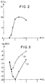
- FIG. 2 carries a diagram representing the variation of an optimal value of a compensation rate, plotted on the ordinate, as a function of the linear chromatic dispersion of a line fiber, plotted on the abscissa.
- FIG. 3 carries two diagrams representing the variations of an error rate plotted on the ordinate, as a function of the linear chromatic dispersion of a line fiber, plotted on the abscissa.
- the time jitter compensation means comprise a compensation member. 14 transmitting the transmission pulses between the output 2B of the line fiber and the receiver 10, and this member has a negative overall chromatic dispersion partially correcting this time jitter.
- a compensation rate TC is defined such that the absolute value of this negative overall chromatic dispersion is equal to the product of this compensation rate by the positive overall chromatic dispersion introduced by the line fiber 2.
- this rate TC is between 1 % and 50% and more preferably between 2% and 20%.
- the reduction in the time jitter is maximum for a compensation rate equal to 50%.
- the compensating member being unable to exhibit the soliton effect, it causes a widening of the pulses, and therefore an increase in the errors resulting from the interference between successive symbols. This is why there is an optimal value for the dispersion of the compensating member, significantly reducing the time jitter, without excessively increasing the interference between symbols.
- This compensation member can simply be constituted by an optical fiber called "compensation" having a negative linear chromatic dispersion being worth for example: - 30 ps / nm.km. An optimal length of this fiber is then 54 km.
- Figures 2 and 3 relate to the previously mentioned case, with the additional assumption that the amplifier means used consists of localized optical amplifiers such as the amplifier 3 and spaced 30 km apart.
- the linear chromatic dispersions DL of the line fiber are expressed on the abscissa in ps / nm.km.
- Diagram 20 corresponds to the absence of any means of compensation for the time jitter.
- Diagram 22 corresponds to the use of a compensation member optimized in accordance with the present invention.
Abstract
Description
La présente invention concerne la transmission d'information sur une fibre optique sous la forme d'impulsions optiques. Il est connu que, dans une telle fibre, la compensation de deux types d'effets peut permettre à des impulsions brèves de forme convenable, appelées "solitons", de se propager sans déformation. L'un de ces types est constitué par un effet dispersif créant une dispersion chromatique qui affecte les vitesses de propagation de groupe de ces impulsions. L'autre est constitué par des effets optiques non linéaires de type Kerr. Ce phénomène de compensation est parfois appelé "effet soliton".The present invention relates to the transmission of information over an optical fiber in the form of optical pulses. It is known that, in such a fiber, the compensation of two types of effects can allow short pulses of suitable shape, called "solitons", to propagate without deformation. One of these types is constituted by a dispersive effect creating a chromatic dispersion which affects the group propagation speeds of these pulses. The other is made up of non-linear Kerr-type optical effects. This compensation phenomenon is sometimes called the "soliton effect".
Pour que cet effet soliton soit obtenu plusieurs conditions doivent être satisfaites simultanément: Tout d'abord les impulsions doivent être brèves: Pour une transmission à 10 Gbit/s, par exemple, elles doivent avoir une durée d'environ 20 ps, à mi intensité. La courbe de variation de leur intensité I en fonction du temps t doit présenter une forme définie selon l'expression![]()
Io étant l'intensité de crête et τ étant une durée proportionnelle à la durée de l'impulsion à mi-hauteur. Elles doivent ensuite être "proches de la limite de Fourier", c'est-à-dire que le produit de leur durée par leur largeur spectrale doit être inférieur à une limite d'environ 0,7 et s'approcher autant que possible d'une limite théorique de 0,32. Enfin leur intensité doit être à peu près maintenue en cours de propagation. En ce qui concerne la fibre un rapport convenable doit être réalisé entre d'une part le produit d'une intensité de crête des impulsions optiques par une constante représentative de l'effet Kerr, d'autre part le produit du carré d'une largeur spectrale de ces impulsions par une constante représentative de l'effet de dispersion chromatique apparaissant dans chaque unité de longueur de cette fibre. Cette dernière constante est une dispersion chromatique linéique dont le produit par la longueur de la fibre constitue une dispersion chromatique globale de celle-ci c'est-à-dire une dispersion chromatique se manifestant entre l'entrée et la sortie de cette fibre. Pour l'obtention de l'effet soliton ces dispersions chromatiques linéique et globale doivent être positives, ce qui est obtenu si la longueur d'onde centrale de l'impulsion est supérieure à une longueur d'onde qui est caractéristique de la fibre et qui y annule la dispersion.For this soliton effect to be obtained several conditions must be satisfied simultaneously: First of all the pulses must be brief: For a transmission at 10 Gbit / s, for example, they must have a duration of approximately 20 ps, at mid intensity . The curve of variation of their intensity I as a function of time t must have a shape defined according to the expression ![]()
I o being the peak intensity and τ being a duration proportional to the duration of the pulse at mid-height. They must then be "close to the Fourier limit", that is to say that the product of their duration by their spectral width must be less than a limit of about 0.7 and approach as much as possible d '' a theoretical limit of 0.32. Finally, their intensity must be more or less maintained during propagation. As regards the fiber, a suitable relationship must be established between on the one hand the product of a peak intensity of the optical pulses by a constant representative of the Kerr effect, on the other hand the product of the square of a width spectral of these pulses by a constant representative of the chromatic dispersion effect appearing in each unit of length of this fiber. This last constant is a linear chromatic dispersion whose product by the length of the fiber constitutes an overall chromatic dispersion thereof, that is to say a chromatic dispersion occurring between the entry and the exit of this fiber. To obtain the soliton effect, these linear and overall chromatic dispersions must be positive, which is obtained if the central wavelength of the pulse is greater than a wavelength which is characteristic of the fiber and which cancels the dispersion there.
L'utilisation de l'effet soliton peut présenter des avantages importants dans les liaisons transocéaniques (6000 - 9000 km) à haut débit utilisant un codage binaire. Compte tenu du fait que les fibres optiques présentent des pertes qui provoquent un affaiblissement naturel des impulsions, les grandes distances de transmission peuvent être atteintes par la propagation des solitons dans des fibres dont les pertes sont compensées par des amplificateurs optiques. Ces derniers sont typiquement constitués par des fibres dopées à l'erbium. Ils sont répartis sur la longueur de la liaison pour limiter les variations de la puissance optique des impulsions afin de leur conserver leur caractère de solitons.The use of the soliton effect can have significant advantages in high speed transoceanic links (6000 - 9000 km) using binary coding. In view of the fact that the optical fibers exhibit losses which cause a natural weakening of the pulses, the long transmission distances can be reached by the propagation of the solitons in fibers whose losses are compensated for by optical amplifiers. The latter typically consist of fibers doped with erbium. They are distributed over the length of the link to limit variations in the optical power of the pulses in order to keep them their soliton character.
Cependant, le bruit inévitablement émis par ces amplificateurs limite les distances et les débits accessibles, ceci parce que ce bruit provoque une dégradation du rapport signal à bruit et l'apparition d'une "gigue temporelle" des impulsions à l'entrée de l'organe de réception.However, the noise inevitably emitted by these amplifiers limits the distances and the flow rates accessible, this because this noise causes a degradation of the signal to noise ratio and the appearance of a "temporal jitter" of the pulses at the input of the receiving agency.
Cette gigue temporelle est dite de Gordon-Haus. Elle résulte du fait que la superposition du bruit d'amplification à un soliton est équivalente à une modification de la longueur d'onde centrale de ce soliton. Ce changement de longueur d'onde provoque une variation de la vitesse de propagation dans la fibre en raison de la dispersion chromatique de cette dernière. La nature aléatoire du bruit provoque une variation aléatoire de la vitesse des différents solitons et donc, en réception, un déplacement temporel aléatoire des impulsions. Ce déplacement, qui constitue ladite gigue temporelle, est à l'origine d'un accroissement du taux des erreurs de transmission.This temporal jitter is called Gordon-Haus. It results from the fact that the superimposition of the amplification noise on a soliton is equivalent to a modification of the central wavelength of this soliton. This change in wavelength causes a variation in the speed of propagation in the fiber due to the chromatic dispersion of the latter. The random nature of the noise causes a random variation in the speed of the different solitons and therefore, on reception, a random temporal displacement of the pulses. This displacement, which constitutes said time jitter, is the source of an increase in the rate of transmission errors.
On peut consulter à ce sujet les deux articles suivants:
- Gordon and Mollenauer, "Effect of fiber nonlinearities and amplifier spacing on ultra-long distance transmission", J.Ligth. Technol., 9, 170 (1991).
- Gordon and Haus, "Random walk of coherently amplified solitons in optical fiber transmission", Optics Lett., 11,665 (1986)
- Gordon and Mollenauer, "Effect of fiber nonlinearities and amplifier spacing on ultra-long distance transmission", J.Ligth. Technol., 9, 170 (1991).
- Gordon and Haus, "Random walk of coherently amplified solitons in optical fiber transmission", Optics Lett., 11,665 (1986)
Pour minimiser le taux d'erreur d'un système de transmission à solitons deux conditions antagonistes doivent être simultanément remplies. Selon une première condition la gigue temporelle doit être limitée ce qui amène à choisir une fibre présentant une dispersion chromatique linéique faible. Selon la deuxième condition le rapport signal à bruit doit être maintenu à une valeur suffisamment élevée. Pour cela il est nécessaire que les impulsions transmises présentent une grande énergie. Cette dernière provoque de forts effets non linéaires. Elle impose donc de choisir une fibre de ligne présentant une forte dispersion chromatique linéique qui est nécessaire pour réaliser la compensation de ces forts effets non linéaires, cette compensation étant elle même nécessaire pour obtenir l'effet soliton.To minimize the error rate of a soliton transmission system, two conflicting conditions must be fulfilled simultaneously. According to a first condition, the time jitter must be limited, which leads to choosing a fiber having a low linear chromatic dispersion. According to the second condition, the signal to noise ratio must be maintained at a sufficiently high value. For this it is necessary that the transmitted pulses have a high energy. The latter causes strong nonlinear effects. It therefore requires choosing a line fiber having a high linear chromatic dispersion which is necessary to compensate for these strong non-linear effects, this compensation being itself necessary for obtaining the soliton effect.
Ces deux conditions amènent à choisir une valeur intermédiaire optimale de la dispersion chromatique linéique pour minimiser le taux global d'erreurs de transmission. Lorsqu'une telle valeur optimale est réalisée, il apparaît que la dégradation du rapport signal à bruit et la gigue temporelle contribuent toute deux d'une manière importante à ce taux global minimisé.These two conditions lead to choosing an optimal intermediate value of the linear chromatic dispersion in order to minimize the overall rate of transmission errors. When such an optimal value is achieved, it appears that the degradation of the signal to noise ratio and the time jitter both contribute significantly to this minimized overall rate.
C'est pourquoi il a été notamment proposé de limiter cette gigue temporelle. Deux méthodes connues ont été proposées pour cela. Elles agissent toutes deux en des points intermédiaires d'une liaison de grande longueur, c'est-à-dire à distance des stations d'émission et de réception.This is why it has been proposed in particular to limit this temporal jitter. Two known methods have been proposed for this. They both act at intermediate points on a very long link, that is to say at a distance from the transmitting and receiving stations.
Une première méthode est connue par un document "10 Gb/s soliton data transmission over one million kilometres", NAKAZAWA, YAMADA, KUBOTA, SUZIKI, Elect. Letters, 27, 1270 (1991). Selon cette méthode on reconstitue de place en place la forme des impulsions pour maintenir à la fois leur caractère de solitons et leurs espacements temporels mutuels.A first method is known from a document "10 Gb / s soliton data transmission over one million kilometers", NAKAZAWA, YAMADA, KUBOTA, SUZIKI, Elect. Letters, 27 , 1270 (1991). According to this method, the shape of the pulses is reconstituted from place to place in order to maintain both their character of solitons and their mutual temporal spacings.
La deuxième méthode connue a été proposée par un document "Soliton Transmission Control" MECOZZI, MOORES, HAUS, LAI, Optics Letters, 16, 1841 (1992). Elle consiste à réaliser de place en place un filtrage fréquentiel des impulsions pour maintenir la valeur de leur longueur d'onde centrale.The second known method was proposed by a document "Soliton Transmission Control" MECOZZI, MOORES, HAUS, LAI, Optics Letters, 16 , 1841 (1992). It consists in carrying out from place to place a frequency filtering of the pulses to maintain the value of their central wavelength.
Ces deux méthodes connues sont coûteuses car elles présentent de grosses difficultés techniques: synchronisation des modulateurs pour la première et asservissement de la longueur d'onde centrale des filtres pour la seconde.These two known methods are costly because they present great technical difficulties: synchronization of the modulators for the first and slaving of the central wavelength of the filters for the second.
La présente invention a notamment pour but de limiter d'une manière simple les taux des erreurs de transmission affectant une liaison utilisant des solitons, lorsque ces erreurs résultent au moins en partie d'une gigue temporelle de Gordon-Haus affectant les impulsions reçues.The object of the present invention is in particular to limit in a simple manner the rates of transmission errors affecting a link using solitons, when these errors result at least in part from a Gordon-Haus temporal jitter affecting the pulses received.
Et dans ce but elle a notamment pour objet un système de de transmission à solitons optiques comportant une fibre de ligne à dispersion chromatique positive et un moyen amplificateur à bruit pour guider et maintenir des solitons portant une information à transmettre, ce système étant caractérisé par le fait qu'il comporte un organe de compensation 14 disposé en aval dudit moyen amplificateur 3, cet organe de compensation présentant une dispersion chromatique négative pour compenser partiellement une gigue temporelle imposée auxdits solitons par ledit moyen amplificateur 3.And for this purpose it has in particular for object a transmission system with optical solitons comprising a line fiber with positive chromatic dispersion and a noise amplifier means for guiding and maintaining solitons carrying information to be transmitted, this system being characterized by fact that it comprises a
Le fait que la dispersion chromatique globale de cet organe de compensation soit négative entraîne que les impulsions optiques reçues par cet organe y perdent nécessairement leur caractère de solitons, c'est-à-dire qu'elles s'y déforment et, notamment, qu'elles s'y élargissent. Ceci est vrai même si cet organe est constitué par une fibre optique présentant un effet Kerr analogue à celui de la fibre de ligne. Or, il est connu qu'un tel élargissement tend à augmenter le taux d'erreurs de transmission. Il a cependant été trouvé, selon cette invention,qu'en fait la présence d'un tel organe de compensation pouvait diminuer ce taux d'erreur.The fact that the overall chromatic dispersion of this compensating member is negative means that the optical pulses received by this member necessarily lose their soliton character there, that is to say that they deform there and, in particular, that 'they widen there. This is true even if this member is constituted by an optical fiber having a Kerr effect analogous to that of the line fiber. However, it is known that such an enlargement tends to increase the rate of transmission errors. It has however been found, according to this invention, that in fact the presence of such a compensating member could reduce this error rate.
A l'aide des figures schématiques ci-jointes, on va décrire plus particulièrement ci-après, à titre d'exemple non limitatif, comment la présente invention peut être mise en oeuvre.Using the attached diagrammatic figures, a more specific description will now be given below, by way of nonlimiting example, how the present invention can be implemented.
La figure 1 représente une vue d'un système de transmission selon la présente invention.Figure 1 shows a view of a transmission system according to the present invention.
La figure 2 porte un diagramme représentant la variation d'une valeur optimale d'un taux de compensation, porté en ordonnées, en fonction de la dispersion chromatique linéique d'une fibre de ligne, portée en abscisses.FIG. 2 carries a diagram representing the variation of an optimal value of a compensation rate, plotted on the ordinate, as a function of the linear chromatic dispersion of a line fiber, plotted on the abscissa.
La figure 3 porte deux diagrammes représentant les variations d'un taux d'erreur porté en ordonnées, en fonction de la dispersion chromatique linéique d'une fibre de ligne, portée en abscisses.FIG. 3 carries two diagrams representing the variations of an error rate plotted on the ordinate, as a function of the linear chromatic dispersion of a line fiber, plotted on the abscissa.
Conformément à la figure 1 un système selon cette invention comporte les éléments suivants qui sont connus quant à leurs fonctions qui vont être indiquées:
- Une fibre de
ligne 2 est constituée par une fibre optique de grande longueur. Cette fibre a uneentrée 2A et unesortie 2B et présente d'une part une dispersion chromatique linéique positive DL, d'autre part un effet Kerr. Cette dispersion et cet effet Kerr se compensent mutuellement pour conserver la forme d'une impulsion optique guidée par cette fibre lorsque cette impulsion présente une intensité, une durée, une forme de variation et une largeur spectrale caractéristiques d'un soliton de cette fibre. Par ailleurs cette fibre applique un affaiblissement naturel progressif aux impulsions optiques qu'elle guide. C'est pourquoi elle est munie sur sa longueur d'unmoyen amplificateur 3 appliquant à ces impulsions une amplification pour compenser au moins partiellement cet affaiblissement naturel. Malheureusement ce moyen amplificateur applique en même temps à ces impulsions un déplacement spectral aléatoire parasite qui, en association avec la dispersion chromatique de cette ligne, entraîne un déplacement temporel aléatoire constituant une gigue temporelle de ces impulsions. - Une source optique 4 fournit sur commande à l'entrée de la fibre de
ligne 2 des impulsions de transmission constituant des solitons de cette fibre. - Un circuit d'entrée de
système 6 reçoit une information à transmettre représentée en 8. Il commande la source optique 4 pour lui faire fournir une succession d'impulsions de transmission. Dans cette succession les intervalles de temps entre les impulsions sont représentatifs de l'information à transmettre. Ces impulsions sont typiquement susceptibles d'être fournies seulement à des instants d'horloge se succèdant régulièrement, l'information étant représentée sous forme binaire par la présence ou l'absence d'impulsions à ces instants. - On prévoit des moyens de compensation de la gigue temporelle.
Enfin un récepteur 10 reçoit les impulsions de transmission à partir de lasortie 2B de la fibre de ligne.
-
Line fiber 2 is made up of a very long optical fiber. This fiber has aninput 2A and anoutput 2B and has on the one hand a positive linear chromatic dispersion DL, on the other hand a Kerr effect. This dispersion and this Kerr effect compensate each other for keep the shape of an optical pulse guided by this fiber when this pulse has an intensity, a duration, a form of variation and a spectral width characteristic of a soliton of this fiber. Furthermore, this fiber applies a progressive natural attenuation to the optical pulses which it guides. This is why it is provided along its length with an amplifier means 3 applying to these pulses an amplification to at least partially compensate for this natural attenuation. Unfortunately, this amplifying means simultaneously applies to these pulses a parasitic random spectral displacement which, in association with the chromatic dispersion of this line, causes a random temporal displacement constituting a temporal jitter of these pulses. - An optical source 4 supplies on command at the input of the
line fiber 2 transmission pulses constituting solitons of this fiber. - A
system input circuit 6 receives information to be transmitted represented at 8. It controls the optical source 4 to cause it to supply a succession of transmission pulses. In this succession the time intervals between the pulses are representative of the information to be transmitted. These pulses are typically capable of being supplied only at regularly occurring clock instants, the information being represented in binary form by the presence or absence of pulses at these instants. - Means of compensation for the time jitter are provided.
- Finally a
receiver 10 receives the transmission pulses from theoutput 2B of the line fiber.
Il traite les intervalles de temps entre ces impulsions pour restituer l'information qui était à transmettre et qui est représentée en 12.It processes the time intervals between these pulses to restore the information which was to be transmitted and which is represented at 12.
Selon la présente invention les moyens de compensation de la gigue temporelle comportent un organe de compensation 14 transmettant les impulsions de transmission entre la sortie 2B de la fibre de ligne et le récepteur 10, et cet organe présente une dispersion chromatique globale négative corrigeant partiellement cette gigue temporelle.According to the present invention, the time jitter compensation means comprise a compensation member. 14 transmitting the transmission pulses between the
On définit un taux de compensation TC tel que la valeur absolue de cette dispersion chromatique globale négative est égale au produit de ce taux de compensation par la dispersion chromatique globale positive introduite par la fibre de ligne 2. De préférence ce taux TC est compris entre 1% et 50% et de préférence encore entre 2% et 20%.A compensation rate TC is defined such that the absolute value of this negative overall chromatic dispersion is equal to the product of this compensation rate by the positive overall chromatic dispersion introduced by the
Plus précisément, la réduction de la gigue temporelle est maximale pour un taux de compensation égal à 50%. Cependant l'organe de compensation ne pouvant pas présenter l'effet soliton, il provoque un élargissement des impulsions, et donc une augmentation des erreurs résultant des interférences entre symboles successifs. C'est pourquoi il existe une valeur optimale de la dispersion de l'organe de compensation, réduisant sensiblement la gigue temporelle, sans augmenter exagérément les interférences entre symboles.More precisely, the reduction in the time jitter is maximum for a compensation rate equal to 50%. However, the compensating member being unable to exhibit the soliton effect, it causes a widening of the pulses, and therefore an increase in the errors resulting from the interference between successive symbols. This is why there is an optimal value for the dispersion of the compensating member, significantly reducing the time jitter, without excessively increasing the interference between symbols.
A titre d'exemple on considérera ci-après le cas d'une liaison à 5 Gb/s sur 9000 km obtenue de manière connue par la transmission de solitons de 40 ps de durée à mi-hauteur (soit 1/5 du temps bit). En l'absence de tout moyen de compensation de la gigue temporelle une dispersion chromatique linéique optimale de la fibre de ligne est positive et vaut: +0.7 ps/nm.km. Une telle liaison présente un taux d'erreur d'environ 10⁻¹⁵. Avec un organe de compensation selon l'invention présentant une dispersion chromatique globale négative valant: - 1620 ps/nm, c'est-à-dire un taux de compensation TC = 18%, la dispersion chromatique linéique optimale de la fibre de ligne devient 1 ps/nm.km et le taux d'erreur atteint 10⁻²⁰ avec l'aide d'un filtre électrique non représenté qui est incorporé dans le récepteur 10 et qui présente une bande passante adaptée telle que 3,2 GHz.As an example, we will consider below the case of a 5 Gb / s connection over 9000 km obtained in a known manner by the transmission of solitons of 40 ps duration at half-height (ie 1/5 of the bit time ). In the absence of any time jitter compensation means, an optimal linear chromatic dispersion of the line fiber is positive and is worth: +0.7 ps / nm.km. Such a link has an error rate of approximately 10⁻¹⁵. With a compensation member according to the invention having a negative overall chromatic dispersion equal to: - 1620 ps / nm, that is to say a compensation rate TC = 18%, the optimal linear chromatic dispersion of the line fiber becomes 1 ps / nm.km and the error rate reaches 10⁻²⁰ with the help of an electrical filter, not shown, which is incorporated in the
Cet organe de compensation peut être simplement constitué par une fibre optique dite "de compensation" présentant une dispersion chromatique linéique négative valant par exemple: - 30 ps/nm.km. Une longueur optimale de cette fibre est alors de 54 km.This compensation member can simply be constituted by an optical fiber called "compensation" having a negative linear chromatic dispersion being worth for example: - 30 ps / nm.km. An optimal length of this fiber is then 54 km.
Les figures 2 et 3 sont relatives au cas précédemment mentionné, avec l'hypothèse complémentaire que le moyen amplificateur utilisé est constitué d'amplificateurs optiques localisés tels que l'amplificateur 3 et espacés de 30 km. Les dispersions chromatiques linéiques DL de la fibre de ligne sont exprimées en abscisses en ps/nm.km.Figures 2 and 3 relate to the previously mentioned case, with the additional assumption that the amplifier means used consists of localized optical amplifiers such as the
Sur la figure 2 le taux de compensation est exprimé en %.In Figure 2 the compensation rate is expressed in%.
Sur la figure 3 les ordonnées représentent le logarithme du taux d'erreur Log (BER). Le diagramme 20 correspond à l'absence de tout moyen de compensation de la gigue temporelle. Le diagramme 22 correspond à l'utilisation d'un organe de compensation optimisé conformément à la présente invention.In Figure 3 the ordinates represent the logarithm of the Log error rate (BER). Diagram 20 corresponds to the absence of any means of compensation for the time jitter. Diagram 22 corresponds to the use of a compensation member optimized in accordance with the present invention.
Claims (6)
Applications Claiming Priority (2)
| Application Number | Priority Date | Filing Date | Title |
|---|---|---|---|
| FR9300856A FR2700901B1 (en) | 1993-01-28 | 1993-01-28 | Soliton transmission system and method. |
| FR9300856 | 1993-01-28 |
Publications (2)
| Publication Number | Publication Date |
|---|---|
| EP0609129A1 true EP0609129A1 (en) | 1994-08-03 |
| EP0609129B1 EP0609129B1 (en) | 1999-04-28 |
Family
ID=9443438
Family Applications (1)
| Application Number | Title | Priority Date | Filing Date |
|---|---|---|---|
| EP94400145A Expired - Lifetime EP0609129B1 (en) | 1993-01-28 | 1994-01-24 | Soliton transmission system |
Country Status (8)
| Country | Link |
|---|---|
| US (1) | US5612808A (en) |
| EP (1) | EP0609129B1 (en) |
| JP (1) | JP3519769B2 (en) |
| AT (1) | ATE179560T1 (en) |
| CA (1) | CA2114369A1 (en) |
| DE (1) | DE69418069T2 (en) |
| ES (1) | ES2131172T3 (en) |
| FR (1) | FR2700901B1 (en) |
Cited By (5)
| Publication number | Priority date | Publication date | Assignee | Title |
|---|---|---|---|---|
| WO1996027956A1 (en) * | 1995-03-04 | 1996-09-12 | Northern Telecom Limited | Method and apparatus for conditioning optical solitons |
| WO1997020403A1 (en) * | 1995-11-27 | 1997-06-05 | British Technology Group Limited | Dispersion management system for soliton optical transmission system |
| GB2277651B (en) * | 1993-04-19 | 1997-12-10 | British Tech Group | Optical communications |
| US6680787B1 (en) | 1995-05-17 | 2004-01-20 | Btg International Limited | Optical communication systems |
| US6738542B1 (en) | 1997-07-30 | 2004-05-18 | Btg International Limited | Optical fibre communication system |
Families Citing this family (12)
| Publication number | Priority date | Publication date | Assignee | Title |
|---|---|---|---|---|
| JP3028906B2 (en) * | 1994-01-27 | 2000-04-04 | ケイディディ株式会社 | Soliton optical communication system and optical transmitting device and optical receiving device thereof |
| JP3522044B2 (en) * | 1996-04-19 | 2004-04-26 | 富士通株式会社 | Optical transmission system |
| JP3748652B2 (en) * | 1997-02-27 | 2006-02-22 | 富士通株式会社 | Optical transmission system using inline amplifier |
| JPH10242909A (en) | 1997-02-27 | 1998-09-11 | Fujitsu Ltd | Optical transmission system |
| US6462849B1 (en) | 1998-09-10 | 2002-10-08 | Northwestern University | Optimizing launch points for dispersion-managed solitons |
| US6151336A (en) | 1998-02-11 | 2000-11-21 | Sorrento Networks, Inc. | Time division multiplexing expansion subsystem |
| US6496300B2 (en) | 1998-02-27 | 2002-12-17 | Fujitsu Limited | Optical amplifier |
| US6441955B1 (en) | 1998-02-27 | 2002-08-27 | Fujitsu Limited | Light wavelength-multiplexing systems |
| US6400478B1 (en) | 1998-04-02 | 2002-06-04 | Sorrento Networks, Inc. | Wavelength-division-multiplexed optical transmission system with expanded bidirectional transmission capacity over a single fiber |
| US6298103B1 (en) | 1998-06-16 | 2001-10-02 | Sorrento Networks Corporation | Flexible clock and data recovery module for a DWDM optical communication system with multiple clock rates |
| US6259542B1 (en) | 1998-08-10 | 2001-07-10 | Pirelli Cavi E Sistemi S.P.A. | Method and apparatus for monitoring dispersive-wave energy to indicate and optimize soliton transmission performance |
| GB0005615D0 (en) * | 2000-03-09 | 2000-05-03 | Univ Southampton | An optical processing device based on fiber grating |
Citations (4)
| Publication number | Priority date | Publication date | Assignee | Title |
|---|---|---|---|---|
| US4261639A (en) * | 1979-11-13 | 1981-04-14 | Bell Telephone Laboratories, Incorporated | Optical pulse equalization in single-mode fibers |
| JPH0296120A (en) * | 1988-10-03 | 1990-04-06 | Nippon Telegr & Teleph Corp <Ntt> | Optical fiber transmission path |
| US4969710A (en) * | 1988-04-08 | 1990-11-13 | Corning Incorporated | Optical fiber transmission path with dispersion compensation |
| JPH04335619A (en) * | 1991-05-13 | 1992-11-24 | Nippon Telegr & Teleph Corp <Ntt> | Optical soliton transmitting method |
Family Cites Families (5)
| Publication number | Priority date | Publication date | Assignee | Title |
|---|---|---|---|---|
| US5035481A (en) * | 1990-08-23 | 1991-07-30 | At&T Bell Laboratories | Long distance soliton lightwave communication system |
| US5140656A (en) * | 1991-08-12 | 1992-08-18 | At&T Bell Laboratories | Soliton optical fiber communication system |
| FR2681202B1 (en) * | 1991-09-06 | 1993-11-12 | Alcatel Cit | OPTICAL COMMUNICATION LINK WITH CORRECTION OF NON-LINEAR EFFECTS, AND METHOD FOR PROCESSING AN OPTICAL SIGNAL. |
| US5361319A (en) * | 1992-02-04 | 1994-11-01 | Corning Incorporated | Dispersion compensating devices and systems |
| US5357364A (en) * | 1992-06-25 | 1994-10-18 | At&T Bell Laboratories | Soliton transmission system having sliding-frequency guiding filters |
-
1993
- 1993-01-28 FR FR9300856A patent/FR2700901B1/en not_active Expired - Fee Related
-
1994
- 1994-01-24 AT AT94400145T patent/ATE179560T1/en not_active IP Right Cessation
- 1994-01-24 DE DE69418069T patent/DE69418069T2/en not_active Expired - Fee Related
- 1994-01-24 EP EP94400145A patent/EP0609129B1/en not_active Expired - Lifetime
- 1994-01-24 ES ES94400145T patent/ES2131172T3/en not_active Expired - Lifetime
- 1994-01-27 CA CA002114369A patent/CA2114369A1/en not_active Abandoned
- 1994-01-28 JP JP00865894A patent/JP3519769B2/en not_active Expired - Fee Related
-
1996
- 1996-02-27 US US08/607,554 patent/US5612808A/en not_active Expired - Fee Related
Patent Citations (4)
| Publication number | Priority date | Publication date | Assignee | Title |
|---|---|---|---|---|
| US4261639A (en) * | 1979-11-13 | 1981-04-14 | Bell Telephone Laboratories, Incorporated | Optical pulse equalization in single-mode fibers |
| US4969710A (en) * | 1988-04-08 | 1990-11-13 | Corning Incorporated | Optical fiber transmission path with dispersion compensation |
| JPH0296120A (en) * | 1988-10-03 | 1990-04-06 | Nippon Telegr & Teleph Corp <Ntt> | Optical fiber transmission path |
| JPH04335619A (en) * | 1991-05-13 | 1992-11-24 | Nippon Telegr & Teleph Corp <Ntt> | Optical soliton transmitting method |
Non-Patent Citations (3)
| Title |
|---|
| PATENT ABSTRACTS OF JAPAN vol. 14, no. 301 (P - 1069) 28 June 1990 (1990-06-28) * |
| PATENT ABSTRACTS OF JAPAN vol. 17, no. 182 (P - 1518) 8 April 1993 (1993-04-08) * |
| S.V.CHERNIKOV ET AL: "70 Gbit/s fibre based source of fundamental solitons at 1550 nm", ELECTRONICS LETTERS., vol. 28, no. 13, 18 June 1992 (1992-06-18), STEVENAGE GB, pages 1210 - 1212 * |
Cited By (10)
| Publication number | Priority date | Publication date | Assignee | Title |
|---|---|---|---|---|
| GB2277651B (en) * | 1993-04-19 | 1997-12-10 | British Tech Group | Optical communications |
| WO1996027956A1 (en) * | 1995-03-04 | 1996-09-12 | Northern Telecom Limited | Method and apparatus for conditioning optical solitons |
| US6680787B1 (en) | 1995-05-17 | 2004-01-20 | Btg International Limited | Optical communication systems |
| WO1997020403A1 (en) * | 1995-11-27 | 1997-06-05 | British Technology Group Limited | Dispersion management system for soliton optical transmission system |
| AU717319B2 (en) * | 1995-11-27 | 2000-03-23 | British Technology Group Limited | Dispersion management system for soliton optical transmission system |
| US6650452B1 (en) | 1995-11-27 | 2003-11-18 | Btg International Limited | Optical communications |
| EP1507345A2 (en) * | 1995-11-27 | 2005-02-16 | Btg International Limited | Optical communications system with dispersion compensation |
| EP1507345A3 (en) * | 1995-11-27 | 2006-04-12 | Btg International Limited | Optical communications system with dispersion compensation |
| US7352970B2 (en) | 1995-11-27 | 2008-04-01 | Btg International Limited | Dispersion management system for soliton optical transmission system |
| US6738542B1 (en) | 1997-07-30 | 2004-05-18 | Btg International Limited | Optical fibre communication system |
Also Published As
| Publication number | Publication date |
|---|---|
| DE69418069T2 (en) | 1999-10-21 |
| JP3519769B2 (en) | 2004-04-19 |
| ES2131172T3 (en) | 1999-07-16 |
| FR2700901A1 (en) | 1994-07-29 |
| DE69418069D1 (en) | 1999-06-02 |
| FR2700901B1 (en) | 1995-02-24 |
| US5612808A (en) | 1997-03-18 |
| CA2114369A1 (en) | 1994-07-29 |
| EP0609129B1 (en) | 1999-04-28 |
| JPH06258675A (en) | 1994-09-16 |
| ATE179560T1 (en) | 1999-05-15 |
Similar Documents
| Publication | Publication Date | Title |
|---|---|---|
| EP0609129B1 (en) | Soliton transmission system | |
| EP0718992B1 (en) | Inline regenerator device of a soliton signal via synchronous solitory modulation using a non-linear optical mirror | |
| EP0862286B1 (en) | Optical regeneration for optical fibre transmission systems with non-soliton signals | |
| FR2685835A1 (en) | VERY LONG DISTANCE TRANSMISSION SYSTEM ON OPTICAL FIBER COMPENSATED FOR DISTORTIONS AT RECEPTION. | |
| FR2781321A1 (en) | QUASI-DISTRIBUTED AMPLIFICATION IN A SOLITON SIGNAL FIBER OPTIC TRANSMISSION SYSTEM | |
| EP0788016A1 (en) | Polarization independent Kerr modulator, and all-optical clock regenerator device having the same | |
| FR2707442A1 (en) | Optical fiber transmission system with on-line distortion compensation. | |
| EP0566464B1 (en) | Optical pulse source and optical soliton transmission system with such a source | |
| EP1087553A1 (en) | Optical regenerator for WDM signals | |
| EP0980538B1 (en) | Device and method for regenerating a train of solitons | |
| EP0818896A1 (en) | Optical data transmission system in soliton format | |
| EP0797321A1 (en) | Method and system for optical transmission by means of solitons | |
| EP1111819B1 (en) | Fiber optic transmission system with noise reduction using a non linear offset of the signals | |
| EP1087554A1 (en) | Optical regenerator limiting the noise in the zeros of a RZ signal | |
| EP1314267A1 (en) | All-optical regenerator for wavelength-division multiplexed signals | |
| CA2270765A1 (en) | Dual filtered soliton signal fiber optics transmission system | |
| FR2757719A1 (en) | REPEATER FOR FIBER OPTICAL TRANSMISSION SYSTEM WITH SOLITON SIGNALS | |
| EP0652653A1 (en) | Optical fibre telecommunication method, link applying this method and pumping system for four wave mixing, particularly for this link | |
| EP1087555A1 (en) | Device for limiting the noise in the "zeros" of optical RZ signals | |
| EP1021004A1 (en) | Method and apparatus for the stabilization of optical solitons | |
| EP1372278A1 (en) | Monolithic semiconductor component for optical signal regeneration | |
| EP0859482A1 (en) | Optical regeneration for soliton wdm fiberoptic transmission systems | |
| CA2319964A1 (en) | Optical power limiter |
Legal Events
| Date | Code | Title | Description |
|---|---|---|---|
| PUAI | Public reference made under article 153(3) epc to a published international application that has entered the european phase |
Free format text: ORIGINAL CODE: 0009012 |
|
| AK | Designated contracting states |
Kind code of ref document: A1 Designated state(s): AT BE CH DE ES FR GB IT LI NL SE |
|
| 17P | Request for examination filed |
Effective date: 19941209 |
|
| 17Q | First examination report despatched |
Effective date: 19970729 |
|
| GRAG | Despatch of communication of intention to grant |
Free format text: ORIGINAL CODE: EPIDOS AGRA |
|
| GRAG | Despatch of communication of intention to grant |
Free format text: ORIGINAL CODE: EPIDOS AGRA |
|
| GRAH | Despatch of communication of intention to grant a patent |
Free format text: ORIGINAL CODE: EPIDOS IGRA |
|
| GRAH | Despatch of communication of intention to grant a patent |
Free format text: ORIGINAL CODE: EPIDOS IGRA |
|
| GRAA | (expected) grant |
Free format text: ORIGINAL CODE: 0009210 |
|
| RAP1 | Party data changed (applicant data changed or rights of an application transferred) |
Owner name: ALCATEL |
|
| AK | Designated contracting states |
Kind code of ref document: B1 Designated state(s): AT BE CH DE ES FR GB IT LI NL SE |
|
| REF | Corresponds to: |
Ref document number: 179560 Country of ref document: AT Date of ref document: 19990515 Kind code of ref document: T |
|
| ITF | It: translation for a ep patent filed |
Owner name: JACOBACCI & PERANI S.P.A. |
|
| REG | Reference to a national code |
Ref country code: CH Ref legal event code: EP |
|
| REG | Reference to a national code |
Ref country code: CH Ref legal event code: NV Representative=s name: CABINET ROLAND NITHARDT CONSEILS EN PROPRIETE INDU |
|
| REF | Corresponds to: |
Ref document number: 69418069 Country of ref document: DE Date of ref document: 19990602 |
|
| GBT | Gb: translation of ep patent filed (gb section 77(6)(a)/1977) |
Effective date: 19990513 |
|
| REG | Reference to a national code |
Ref country code: ES Ref legal event code: FG2A Ref document number: 2131172 Country of ref document: ES Kind code of ref document: T3 |
|
| PGFP | Annual fee paid to national office [announced via postgrant information from national office to epo] |
Ref country code: NL Payment date: 19991216 Year of fee payment: 7 |
|
| PGFP | Annual fee paid to national office [announced via postgrant information from national office to epo] |
Ref country code: CH Payment date: 19991217 Year of fee payment: 7 |
|
| PGFP | Annual fee paid to national office [announced via postgrant information from national office to epo] |
Ref country code: SE Payment date: 19991220 Year of fee payment: 7 |
|
| PGFP | Annual fee paid to national office [announced via postgrant information from national office to epo] |
Ref country code: AT Payment date: 19991221 Year of fee payment: 7 |
|
| PGFP | Annual fee paid to national office [announced via postgrant information from national office to epo] |
Ref country code: BE Payment date: 20000107 Year of fee payment: 7 |
|
| PGFP | Annual fee paid to national office [announced via postgrant information from national office to epo] |
Ref country code: ES Payment date: 20000126 Year of fee payment: 7 |
|
| PLBE | No opposition filed within time limit |
Free format text: ORIGINAL CODE: 0009261 |
|
| STAA | Information on the status of an ep patent application or granted ep patent |
Free format text: STATUS: NO OPPOSITION FILED WITHIN TIME LIMIT |
|
| 26N | No opposition filed | ||
| PG25 | Lapsed in a contracting state [announced via postgrant information from national office to epo] |
Ref country code: AT Free format text: LAPSE BECAUSE OF NON-PAYMENT OF DUE FEES Effective date: 20010124 |
|
| PG25 | Lapsed in a contracting state [announced via postgrant information from national office to epo] |
Ref country code: SE Free format text: LAPSE BECAUSE OF NON-PAYMENT OF DUE FEES Effective date: 20010125 Ref country code: ES Free format text: LAPSE BECAUSE OF NON-PAYMENT OF DUE FEES Effective date: 20010125 |
|
| PG25 | Lapsed in a contracting state [announced via postgrant information from national office to epo] |
Ref country code: LI Free format text: LAPSE BECAUSE OF NON-PAYMENT OF DUE FEES Effective date: 20010131 Ref country code: CH Free format text: LAPSE BECAUSE OF NON-PAYMENT OF DUE FEES Effective date: 20010131 Ref country code: BE Free format text: LAPSE BECAUSE OF NON-PAYMENT OF DUE FEES Effective date: 20010131 |
|
| BERE | Be: lapsed |
Owner name: ALCATEL Effective date: 20010131 |
|
| PG25 | Lapsed in a contracting state [announced via postgrant information from national office to epo] |
Ref country code: NL Free format text: LAPSE BECAUSE OF NON-PAYMENT OF DUE FEES Effective date: 20010801 |
|
| EUG | Se: european patent has lapsed |
Ref document number: 94400145.2 |
|
| REG | Reference to a national code |
Ref country code: CH Ref legal event code: PL |
|
| NLV4 | Nl: lapsed or anulled due to non-payment of the annual fee |
Effective date: 20010801 |
|
| REG | Reference to a national code |
Ref country code: GB Ref legal event code: IF02 |
|
| REG | Reference to a national code |
Ref country code: ES Ref legal event code: FD2A Effective date: 20021116 |
|
| PGFP | Annual fee paid to national office [announced via postgrant information from national office to epo] |
Ref country code: GB Payment date: 20040112 Year of fee payment: 11 |
|
| PGFP | Annual fee paid to national office [announced via postgrant information from national office to epo] |
Ref country code: DE Payment date: 20040123 Year of fee payment: 11 |
|
| PGFP | Annual fee paid to national office [announced via postgrant information from national office to epo] |
Ref country code: FR Payment date: 20040128 Year of fee payment: 11 |
|
| PG25 | Lapsed in a contracting state [announced via postgrant information from national office to epo] |
Ref country code: IT Free format text: LAPSE BECAUSE OF NON-PAYMENT OF DUE FEES;WARNING: LAPSES OF ITALIAN PATENTS WITH EFFECTIVE DATE BEFORE 2007 MAY HAVE OCCURRED AT ANY TIME BEFORE 2007. THE CORRECT EFFECTIVE DATE MAY BE DIFFERENT FROM THE ONE RECORDED. Effective date: 20050124 Ref country code: GB Free format text: LAPSE BECAUSE OF NON-PAYMENT OF DUE FEES Effective date: 20050124 |
|
| PG25 | Lapsed in a contracting state [announced via postgrant information from national office to epo] |
Ref country code: DE Free format text: LAPSE BECAUSE OF NON-PAYMENT OF DUE FEES Effective date: 20050802 |
|
| GBPC | Gb: european patent ceased through non-payment of renewal fee |
Effective date: 20050124 |
|
| PG25 | Lapsed in a contracting state [announced via postgrant information from national office to epo] |
Ref country code: FR Free format text: LAPSE BECAUSE OF NON-PAYMENT OF DUE FEES Effective date: 20050930 |
|
| REG | Reference to a national code |
Ref country code: FR Ref legal event code: ST |