EP0608592B1 - Sternum banding assembly - Google Patents
Sternum banding assembly Download PDFInfo
- Publication number
- EP0608592B1 EP0608592B1 EP93300548A EP93300548A EP0608592B1 EP 0608592 B1 EP0608592 B1 EP 0608592B1 EP 93300548 A EP93300548 A EP 93300548A EP 93300548 A EP93300548 A EP 93300548A EP 0608592 B1 EP0608592 B1 EP 0608592B1
- Authority
- EP
- European Patent Office
- Prior art keywords
- band
- buckle
- channel
- assembly
- clamp
- Prior art date
- Legal status (The legal status is an assumption and is not a legal conclusion. Google has not performed a legal analysis and makes no representation as to the accuracy of the status listed.)
- Expired - Lifetime
Links
Images


Classifications
-
- A—HUMAN NECESSITIES
- A61—MEDICAL OR VETERINARY SCIENCE; HYGIENE
- A61B—DIAGNOSIS; SURGERY; IDENTIFICATION
- A61B17/00—Surgical instruments, devices or methods
- A61B17/56—Surgical instruments or methods for treatment of bones or joints; Devices specially adapted therefor
- A61B17/58—Surgical instruments or methods for treatment of bones or joints; Devices specially adapted therefor for osteosynthesis, e.g. bone plates, screws or setting implements
- A61B17/68—Internal fixation devices, including fasteners and spinal fixators, even if a part thereof projects from the skin
- A61B17/82—Internal fixation devices, including fasteners and spinal fixators, even if a part thereof projects from the skin for bone cerclage
- A61B17/823—Internal fixation devices, including fasteners and spinal fixators, even if a part thereof projects from the skin for bone cerclage for the sternum
-
- B—PERFORMING OPERATIONS; TRANSPORTING
- B25—HAND TOOLS; PORTABLE POWER-DRIVEN TOOLS; MANIPULATORS
- B25B—TOOLS OR BENCH DEVICES NOT OTHERWISE PROVIDED FOR, FOR FASTENING, CONNECTING, DISENGAGING, OR HOLDING
- B25B25/00—Implements for fastening, connecting or tensioning of wire or strip
- B25B25/005—Implements for fastening, connecting or tensioning of wire or strip for applying wire clasps to hose couplings
Definitions
- the present invention relates to an assembly for banding the sternum for use with a hand-held clamp.
- a sternum banding assembly is used for clamping and closing the split halves of the sternum as part of surgery which involves a median sternotomy, such as open heart surgery.
- the surgically opened faces must be approximated, compressed and held together rigidly. This task is complicated by the physiological role of the sternum.
- the sternum is a functional component of the thoracic cage and, with the costal cartilages, serves as the hinge for the "bucket handle" action of the ribs during respiration.
- the incessant motion of the rib cage transmits continuous stresses across the sternum. Any method of closing a split sternum must be able to maintain compression and rigidity across the closure in the face of these constant stresses.
- One technique used in the past involves closing the sternum with a plurality of spaced stainless steel wires. Five or more 20 gauge stainless steel wires are placed either parasternally (around the sternum) or transternally (through the sternum) using a large, swaged-on cutting needle. The needles are cut off and the sternal halves are approximated by twisting the wires. Finally the wires are cut short and the ends are tucked into the adjacent tissue.
- each band may be formed integrally with a surgical needle at one end and a locking member at the other end.
- a surgical needle at one end
- a locking member at the other end.
- U.S. Patent No. 4,535,764 to Ebert.
- Ebert's locking member requires that the band be threaded through an opening in the locking member and bent back over the member and threaded through two other openings, a complicated and time consuming task.
- Another variation is disclosed in U.S. Patent No. 4,730,615 to Sutherland. Sutherland uses a polymer coated metal band with an upstanding head. Adjacent the head is a serrated spine portion which is locked by a metal finger on a channel in the head.
- That banding assembly includes a locking member in the form of a buckle.
- the buckle has a loop segment under the saddle. The segment terminates in a spring tooth adapted to engage an opening in the band when the band is pulled through a channel.
- the channel is defined by "C" shaped flanges extending upwardly from either side of the saddle.
- Threading the band into the channel in the buckle is facilitated through the use of a guide member situated on the band.
- the guide member takes the form of a dome-like element situated on the surface of the band adjacent a narrowed portion.
- the element and the narrow band portion cooperate with the "C" shaped channel defining flanges to assist in threading the band through the channel.
- the preferred embodiment of the present invention provides an improved sternum banding assembly which includes a buckle designed to be engaged by a clamp to facilitate tightening of the band but which has a low profile.
- the assembly eliminates any exposed sharp edges by enclosing the trimmed tail within the buckle. Furthermore insertion of the band into the channel in the buckle is facilitated by a dome-shaped guide element.
- the means for engagement by the clamp in this kind of assembly comprises a loop segment under the saddle of the buckle.
- the assembly is characterized as set forth in Claims 1 and 11.
- the end section of the band after the band is drawn into the channel and locked into position by the locking means, is bent back over the surface-cooperating means (also referred to as channel-defining means).
- the engagement means comprises means for retaining and securing the bent end section.
- the portion of the band that is to be retained has a given width.
- the upstanding elements are normally spaced apart, at their closest point, a distance which is slightly less than this given width.
- the retained portion preferably includes a trimmed end of the band.
- the band has first and second openings.
- Means are provided for attaching the buckle to the band.
- the attaching means comprises first and second elements extending from the buckle and adapted to be received in the first and second band openings, respectively.
- the band to be described also includes a portion proximate the one end. That portion includes a decreased width section and guide member, preferably in the form of a substantially dome-shaped guide element, for assisting in passing the band through the channel in the buckle.
- Another aspect of the invention is a sternum banding assembly for use with a hand-held clamp as set forth in Claim 11.
- the hand-held clamp used with the assembly is preferably one having a pair of clamp arms moveable between proximate and remote positions.
- the clamp may be a conventional towel clamp.
- the opening in each element also referred to later as an "ear" is adapted to receive a different one of the clamp arms.
- a method for banding a sternum with a banding assembly is as follows.
- the banding assembly referred to is the initial assembly having the surgical needle fixed to one end. It is assumed that the clamp is of the type mentioned having arms moveable between remote and proximate positions.
- the method includes the steps of threading the needle and band around or through the sternum parts.
- the needle is then removed from the band end.
- the band end is guided through the channel defining elements in the buckle.
- the buckle is retained with the clamp by moving the arms of the clamp from the remote position to the proximate position and engaging the openings in the upstanding ears.
- the band is tightened by pulling it through the channel as the buckle is retained by the clamp, until the band is locked by the locking member.
- the excess band is cut off, leaving a tail.
- the band tail is bent over the channel-defining elements and placed between the upstanding ears.
- the ears are crimped over the band. They overlie the trimmed end of the band.
- the upstanding ears are spaced apart a distance slightly less than the width of the tail portion of the band retained by the ears.
- the step of placing the band tail between the upstanding ears comprises the step of snap-fitting the band tail between the ears.
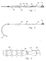
- the banding assembly includes an elongated, thin and relatively wide flat band 10, preferably made of stainless steel.
- a surgical needle 12 extends from one end of band 10. Needle 12 is preferably integral with the band but may be a separate part riveted or otherwise affixed to the band. Mounted proximate the other end of band 10 is a buckle 14.
- Needle 12 is curved to facilitate insertion from one parasternal location, under the sternum halves and then outwardly at an opposite parasternal location.
- Adjacent needle 12 is a band section 16 of gradually increasing width. Section 16 has protrusions or ripples 18 on the top surface. Ripples 18 serve to gently expand the opening in the bone to permit the band to pass through, even when kinked or distorted.
- ripple section 16 is a relatively narrow section 19 which widens to the main band section 20.
- a dome-shaped guide member 22 which extends above the band surface, preferably to the plane of the top surface of ripples 18.
- Member 22 facilitates entry of the main section 20 of the band into the channel in buckle 14.
- Main section 20 has a plurality of spaced slots 24. Slots 24 are adapted to be engaged by the locking mechanism 37 in the buckle.
- the buckle 14 comprises a substantially planar floor 26 having downwardly extending tabs 28, 30 at the forward and rear edge, respectively.
- Tabs 28, 30 are adapted to extend through spaced openings near the end of band section 20.
- Tabs 28, 30 are bent inwardly to secure buckle 14 to band 10.
- a pair of oppositely oriented spaced "C" shaped flanges 32 extend upwardly from opposite sides of floor 26, beginning at the forward end of the buckle and extending toward the rear for approximately one third of the length of the buckle.
- Flanges 32 are relatively thick and rigid and define the channel into which band 10 will be received.
- the inwardly extending top portions 34 of the flanges are inclined upwardly, away from floor 26.
- the channel is wedge shaped, being smallest at its mouth and gradually becoming larger toward the rear of the buckle.
- Tooth 36 Extending upwardly from floor 26, toward the plane of top portions 34, is a locking tooth 36. Tooth 36 is adapted to be received within one of the slots 24 in band 10 to lock the band in position within the channel defined by flanges 32.
- Ears 38 are slightly curved toward each other such that the top edges 40 of the ears are the points which are closest together. Edges 40 are spaced apart by a dimension which is slightly less than the width of band section 20. The flexibility of the stainless steel material of which ears 38 are made permits a section of the band to "snap-fit" between the ears as explained below.
- Ears 38 are each provided with openings 41, shaped and sized to accept the moveable arms of a conventional towel clamp.
- the buckle can be engaged and retained by the arms of a towel clamp as the band is pulled through the channel and tightened into the locking position such that tooth 36 protrudes into one of the slots 24 in the band.
- Ears 38 serve the additional purpose of permanently retaining the tail 42 of the band, after it has been trimmed, in close face to face relation with spring element 37, in a way which covers any sharp edges of the band which may result from trimming the tail.
- the band is locked in position in the channel, it is trimmed to have a tail with a length about as long as the buckle.
- the tail is bent back over flanges 32, toward the rear of the buckle, and snap fits between ears 38.
- Ears 38 are then crimped inwardly, covering the edges of the tail band. In this way, sharp or jagged edges are protected and a low profile is achieved.
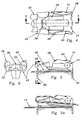
- Figs. 9(a)-9(g) show the various operations involved.
- needle 12 is threaded through or around the sternum sections, as shown in Fig. 9(a). Hemostats or needle holders are used to manipulate the band and needle.
- the needle 12 is cut off, about an inch from narrow section 18.
- the narrow section 18 is then inserted between flanges 32 and dome-shaped member 22 guides the main section 20 of the band into the channel (Fig. 9(c)).
- a clamp is used to pull the band tight while the buckle is retained by a towel clamp whose arms are received in openings 41 (Fig. 9(d)).
- tooth 36 lodges in one of the slots 24 urged upwardly by spring element 37, to lock the band within the channel.
- the band is bent upwardly, 90° from floor 26 of the buckle and trimmed to form a tail 42, approximately 4 slots long (Fig. 9(e)).
- Tail 42 is bent back over the buckle and particularly over flanges 32 and "snap fit" between ears 38 as illustrated in Fig. 9(f). Ears 38 are crimped to overlap the edges of the tail. (Fig. 9(g). In this way, the tail is permanently retained within the buckle and no sharp edges are exposed.
- the entire procedure can be performed quickly and efficiently, using only conventional operating room instruments.
- the resulting structure has a low profile, with no protruding parts or sharp edges.
- the band is reliably locked by the tooth and held securely by the folded tail 42.
Landscapes
- Health & Medical Sciences (AREA)
- Orthopedic Medicine & Surgery (AREA)
- Life Sciences & Earth Sciences (AREA)
- Engineering & Computer Science (AREA)
- Surgery (AREA)
- Heart & Thoracic Surgery (AREA)
- General Health & Medical Sciences (AREA)
- Biomedical Technology (AREA)
- Neurology (AREA)
- Medical Informatics (AREA)
- Molecular Biology (AREA)
- Animal Behavior & Ethology (AREA)
- Nuclear Medicine, Radiotherapy & Molecular Imaging (AREA)
- Public Health (AREA)
- Veterinary Medicine (AREA)
- Mechanical Engineering (AREA)
- Orthopedics, Nursing, And Contraception (AREA)
- Corsets Or Brassieres (AREA)
- Surgical Instruments (AREA)
Description
Claims (17)
- An assembly for banding the sternum for use with a hand-held clamp, comprising an elongate flexible band (10), a needle (12) at one end of the band (10) and a buckle (14) proximate the other end of the band (10), the buckle comprising a surface (26) and means (34) co-operating with said surface (26) to define a channel in which the band is receivable, means (36 and 37) for locking a portion (24) of the band in said channel to secure the band in a sternum banding loop, and means (38) for engagement by the clamp to permit the buckle (14) to be retained by the clamp as said band portion (24) is locked into said channel by said locking means (36 and 37), characterized in that:said clamp engagement means (38) comprises a pair of upstanding elements aligned with said channel, each element having a respective opening (41) therein to receive a respective part of the clamp.
- An assembly as claimed in Claim 1 in which said engagement means (38) comprises retaining means (40) in which a further portion of said band is retainable after bending back over said surface-cooperating means (34) the band extending from said channel.
- An assembly as claimed in Claim 2 in which said retaining means (40) comprises portions of said upstanding elements (38).
- An assembly as claimed in Claim 1 in which said channel is located at the forward end of the buckle and said upstanding elements of said engagement means (38) are rearward of the channel and comprise retaining means (40) for retaining a further portion of the band (10) extending from said channel having bent the band back over said surface-cooperating means (34).
- An assembly as claimed in Claim 2, 3 or 4 wherein said further portion of the band has a given width and wherein said retaining means (40) are normally spaced apart, at their closest point, a distance which is slightly less than said given width.
- An assembly as claimed in any one of Claims 1 to 5 in which the band comprises a guide member (22) for guiding the band through said channel in forming said loop.
- An assembly as claimed in Claim 6 in which said guide-member (22) is dome-shaped.
- An assembly as claimed in Claim 6 in which said surface-cooperating means (34) defines with said surface (26) a wedge-shaped channel (Fig. 5) narrowing in the direction toward the forward end of the buckle (14).
- An assembly as claimed in Claim 6 or 7 wherein said band comprises a section (19) of decreased width adjacent said dome-shaped guide member (22) at the side thereof toward said one end of the band (10).
- An assembly as claimed in any preceding claim wherein said band (10) has first and second openings proximate said other end thereof, and said buckle (14) comprises first (28) and second (30) elements extending from said buckle (14) and received in said first and second band opening, respectively, to attach the buckle (14) to the band.
- A sternum banding assembly for use with a hand-held clamp, comprising an elongate flexible band formed to provide a loop (10), one end of said band formed by trimming, and a buckle (14) proximate the other end of the band (10), the buckle (14) comprising a surface (26) and means (34) cooperating with said surface (26) to define a channel in which a portion (24) of the band (10) is received, said loop extending from said other end to said portion (24) of the band, means (36 and 37) for locking said band portion (24) in the channel, and means (38) for engagement by the clamp to permit the buckle (14) to be retained by the clamp as said band portion (24) is locked into the buckle (14) by said locking means (36 and 37), characterized in that:said clamp engagement means (38) comprises a pair of upstanding elements aligned with said channel, each element having a respective opening therein (41) to receive a respective part of the clamp.
- An assembly as claimed in Claim 11 in which said engagement means (38) comprises retaining means (40) into which a further portion of the band including said trimmed end is retained, said further portion and the portion (24) of the band locked in said channel being connected by a portion of the band (10) bent back over said surface-cooperating means (34).
- An assembly as claimed in Claim 12 in which said retaining means (40) comprises portions of said upstanding elements (38).
- An assembly as claimed in Claim 11 in which said channel is toward the forward end of the buckle (14) and said upstanding elements of said engagement means (38) are located rearwardly of said channel and comprise retaining means (40) retaining said further portion of the band and overlying said trimmed end.
- An assembly as claimed in Claim 12, 13 or 14 in which said retaining means (40) are spaced apart, at their closest point, a distance less than the width of said further portion of the band.
- An assembly as claimed in any one of Claims 11 to 15 in which said surface-cooperating means (34) defines with said surface (26) a wedge-shaped channel (Fig. 5) narrowing toward the forward end of the buckle (14).
- An assembly as claimed in any one of Claims 11 to 16 wherein said band (10) has first and second openings proximate said other end thereof, and said buckle (14) comprises first (28) and second (30) elements extending from said buckle (14) and received in said first and second band opening, respectively, to attach the buckle to the band (10).
Priority Applications (3)
| Application Number | Priority Date | Filing Date | Title |
|---|---|---|---|
| CA002088119A CA2088119C (en) | 1993-01-26 | 1993-01-26 | Sternum banding assembly |
| EP93300548A EP0608592B1 (en) | 1993-01-26 | 1993-01-26 | Sternum banding assembly |
| DE1993620168 DE69320168T2 (en) | 1993-01-26 | 1993-01-26 | Cerclage device for closing the breastbone |
Applications Claiming Priority (2)
| Application Number | Priority Date | Filing Date | Title |
|---|---|---|---|
| CA002088119A CA2088119C (en) | 1993-01-26 | 1993-01-26 | Sternum banding assembly |
| EP93300548A EP0608592B1 (en) | 1993-01-26 | 1993-01-26 | Sternum banding assembly |
Publications (2)
| Publication Number | Publication Date |
|---|---|
| EP0608592A1 EP0608592A1 (en) | 1994-08-03 |
| EP0608592B1 true EP0608592B1 (en) | 1998-08-05 |
Family
ID=25675845
Family Applications (1)
| Application Number | Title | Priority Date | Filing Date |
|---|---|---|---|
| EP93300548A Expired - Lifetime EP0608592B1 (en) | 1993-01-26 | 1993-01-26 | Sternum banding assembly |
Country Status (2)
| Country | Link |
|---|---|
| EP (1) | EP0608592B1 (en) |
| CA (1) | CA2088119C (en) |
Cited By (5)
| Publication number | Priority date | Publication date | Assignee | Title |
|---|---|---|---|---|
| US8128629B2 (en) | 2009-01-22 | 2012-03-06 | Ebi, Llc | Rod coercer |
| US8137357B2 (en) | 2009-01-22 | 2012-03-20 | Ebi, Llc | Rod coercer |
| EP3042622A1 (en) | 2015-01-09 | 2016-07-13 | Stryker European Holdings I, LLC | Implant for bone fixation |
| EP3320868A1 (en) | 2016-11-11 | 2018-05-16 | Stryker European Holdings I, LLC | Implant for bone fixation |
| US11576707B2 (en) | 2013-07-11 | 2023-02-14 | Stryker European Operations Holdings Llc | Fixation assembly with a flexible elongated member for securing parts of a sternum |
Families Citing this family (9)
| Publication number | Priority date | Publication date | Assignee | Title |
|---|---|---|---|---|
| BRMU8501134Y1 (en) * | 2005-06-06 | 2016-05-03 | João Bosco De Oliveira | constructive improvement introduced in metal clamps for use in the field of surgical medicine |
| EP2965702B1 (en) | 2009-05-12 | 2018-11-07 | Synthes GmbH | Bone fixation element with self-retaining cable tie |
| US9084644B2 (en) | 2011-02-02 | 2015-07-21 | DePuy Synthes Products, Inc. | Bone fixation assembly |
| CA2868471C (en) | 2012-03-28 | 2020-09-01 | DePuy Synthes Products, LLC | Bone fixation member systems and methods of use |
| JP6339106B2 (en) | 2013-01-25 | 2018-06-06 | デピュイ・シンセス・プロダクツ・インコーポレイテッド | Cap for implant and implant assembly |
| WO2014189911A1 (en) * | 2013-05-20 | 2014-11-27 | University Of Minnesota | Dental occlusion and tension band ties, systems and methods |
| US9603646B2 (en) | 2014-05-30 | 2017-03-28 | DePuy Synthes Products, Inc. | Bone fixation assembly |
| WO2018085899A1 (en) * | 2016-11-14 | 2018-05-17 | Aspire Surgical Pty Ltd | Medical device for gastric reductions |
| CN113712656B (en) * | 2021-09-13 | 2023-08-08 | 上海火点医疗器械有限公司 | Sternum fixation system |
Family Cites Families (3)
| Publication number | Priority date | Publication date | Assignee | Title |
|---|---|---|---|---|
| US4667662A (en) * | 1984-03-05 | 1987-05-26 | Davol, Inc. | Cerclage device |
| US4813416A (en) * | 1987-03-18 | 1989-03-21 | The Research Foundation Of State University Of New York | Bonding assembly and method for sternum closing |
| DE4021246A1 (en) * | 1990-07-04 | 1992-01-09 | Gundolf Ferdinand | Holding fractured bone in place - involves use of pipe clip with tensioning screw |
-
1993
- 1993-01-26 EP EP93300548A patent/EP0608592B1/en not_active Expired - Lifetime
- 1993-01-26 CA CA002088119A patent/CA2088119C/en not_active Expired - Fee Related
Cited By (11)
| Publication number | Priority date | Publication date | Assignee | Title |
|---|---|---|---|---|
| US8128629B2 (en) | 2009-01-22 | 2012-03-06 | Ebi, Llc | Rod coercer |
| US8137357B2 (en) | 2009-01-22 | 2012-03-20 | Ebi, Llc | Rod coercer |
| US8449549B2 (en) | 2009-01-22 | 2013-05-28 | Ebi, Llc | Rod coercer |
| US8979862B2 (en) | 2009-01-22 | 2015-03-17 | Ebi, Llc | Rod coercer |
| US11576707B2 (en) | 2013-07-11 | 2023-02-14 | Stryker European Operations Holdings Llc | Fixation assembly with a flexible elongated member for securing parts of a sternum |
| EP3042622A1 (en) | 2015-01-09 | 2016-07-13 | Stryker European Holdings I, LLC | Implant for bone fixation |
| US11259853B2 (en) | 2015-01-09 | 2022-03-01 | Stryker European Operations Holdings Llc | Implant for bone fixation |
| US12396772B2 (en) | 2015-01-09 | 2025-08-26 | Stryker European Operations Holdings Llc | Implant for bone fixation |
| EP3320868A1 (en) | 2016-11-11 | 2018-05-16 | Stryker European Holdings I, LLC | Implant for bone fixation |
| US10856921B2 (en) | 2016-11-11 | 2020-12-08 | Stryker European Holdings I, Llc | Implant for bone fixation |
| US11596458B2 (en) | 2016-11-11 | 2023-03-07 | Stryker European Operations Holdings Llc | Implant for bone fixation |
Also Published As
| Publication number | Publication date |
|---|---|
| CA2088119C (en) | 1998-09-01 |
| CA2088119A1 (en) | 1994-07-27 |
| EP0608592A1 (en) | 1994-08-03 |
Similar Documents
| Publication | Publication Date | Title |
|---|---|---|
| US5366461A (en) | Sternum banding assembly | |
| US5972006A (en) | Buckle securing means for sternum banding assembly | |
| EP0608592B1 (en) | Sternum banding assembly | |
| US4813416A (en) | Bonding assembly and method for sternum closing | |
| US5330489A (en) | Sternum closure buckle | |
| US9113975B2 (en) | Sternum band tensioner device, system and method | |
| US5462542A (en) | Sternum buckle with serrated strap | |
| EP1006962B1 (en) | Oral anchorage | |
| US5356417A (en) | Absorbable sternum closure buckle | |
| US4535764A (en) | Surgical bone tie | |
| US6514255B1 (en) | Sublaminar spinal fixation apparatus | |
| EP3019101B1 (en) | Fixation assembly with a flexible elongated member for securing parts of a sternum | |
| US20070055258A1 (en) | Suture band | |
| US5356412A (en) | Sternum buckle with rotational engagement and method of closure | |
| US5797916A (en) | Trochanteric reattachment cerclage device | |
| US20120041441A1 (en) | Cable tie system for stabilizing bone | |
| US11596458B2 (en) | Implant for bone fixation | |
| US20060195101A1 (en) | Sternum closure device having locking member | |
| WO2003041600A1 (en) | Spinal cable system | |
| EP0587635A1 (en) | Medical/surgical devices | |
| JPH08500261A (en) | Chest closure cable and method | |
| WO2001017446A2 (en) | Haemostatic and/or reinforcing surgical suture system for sternal cerclages | |
| EP1477144B1 (en) | Tool for corrective treatment of onychocryptosis | |
| EP3750497A2 (en) | Sternal closure strap device |
Legal Events
| Date | Code | Title | Description |
|---|---|---|---|
| PUAI | Public reference made under article 153(3) epc to a published international application that has entered the european phase |
Free format text: ORIGINAL CODE: 0009012 |
|
| AK | Designated contracting states |
Kind code of ref document: A1 Designated state(s): BE CH DE ES FR GB IT LI NL |
|
| 17P | Request for examination filed |
Effective date: 19950131 |
|
| 17Q | First examination report despatched |
Effective date: 19960614 |
|
| GRAG | Despatch of communication of intention to grant |
Free format text: ORIGINAL CODE: EPIDOS AGRA |
|
| GRAG | Despatch of communication of intention to grant |
Free format text: ORIGINAL CODE: EPIDOS AGRA |
|
| GRAH | Despatch of communication of intention to grant a patent |
Free format text: ORIGINAL CODE: EPIDOS IGRA |
|
| GRAH | Despatch of communication of intention to grant a patent |
Free format text: ORIGINAL CODE: EPIDOS IGRA |
|
| GRAA | (expected) grant |
Free format text: ORIGINAL CODE: 0009210 |
|
| AK | Designated contracting states |
Kind code of ref document: B1 Designated state(s): BE CH DE ES FR GB IT LI NL |
|
| PG25 | Lapsed in a contracting state [announced via postgrant information from national office to epo] |
Ref country code: NL Free format text: LAPSE BECAUSE OF FAILURE TO SUBMIT A TRANSLATION OF THE DESCRIPTION OR TO PAY THE FEE WITHIN THE PRESCRIBED TIME-LIMIT Effective date: 19980805 Ref country code: LI Free format text: LAPSE BECAUSE OF FAILURE TO SUBMIT A TRANSLATION OF THE DESCRIPTION OR TO PAY THE FEE WITHIN THE PRESCRIBED TIME-LIMIT Effective date: 19980805 Ref country code: IT Free format text: LAPSE BECAUSE OF FAILURE TO SUBMIT A TRANSLATION OF THE DESCRIPTION OR TO PAY THE FEE WITHIN THE PRE;WARNING: LAPSES OF ITALIAN PATENTS WITH EFFECTIVE DATE BEFORE 2007 MAY HAVE OCCURRED AT ANY TIME BEFORE 2007. THE CORRECT EFFECTIVE DATE MAY BE DIFFERENT FROM THE ONE RECORDED.SCRIBED TIME-LIMIT Effective date: 19980805 Ref country code: FR Free format text: LAPSE BECAUSE OF FAILURE TO SUBMIT A TRANSLATION OF THE DESCRIPTION OR TO PAY THE FEE WITHIN THE PRESCRIBED TIME-LIMIT Effective date: 19980805 Ref country code: ES Free format text: THE PATENT HAS BEEN ANNULLED BY A DECISION OF A NATIONAL AUTHORITY Effective date: 19980805 Ref country code: CH Free format text: LAPSE BECAUSE OF FAILURE TO SUBMIT A TRANSLATION OF THE DESCRIPTION OR TO PAY THE FEE WITHIN THE PRESCRIBED TIME-LIMIT Effective date: 19980805 Ref country code: BE Free format text: LAPSE BECAUSE OF FAILURE TO SUBMIT A TRANSLATION OF THE DESCRIPTION OR TO PAY THE FEE WITHIN THE PRESCRIBED TIME-LIMIT Effective date: 19980805 |
|
| REG | Reference to a national code |
Ref country code: CH Ref legal event code: EP |
|
| REF | Corresponds to: |
Ref document number: 69320168 Country of ref document: DE Date of ref document: 19980910 |
|
| EN | Fr: translation not filed | ||
| NLV1 | Nl: lapsed or annulled due to failure to fulfill the requirements of art. 29p and 29m of the patents act | ||
| REG | Reference to a national code |
Ref country code: CH Ref legal event code: PL |
|
| PLBE | No opposition filed within time limit |
Free format text: ORIGINAL CODE: 0009261 |
|
| 26N | No opposition filed | ||
| REG | Reference to a national code |
Ref country code: GB Ref legal event code: IF02 |
|
| PGFP | Annual fee paid to national office [announced via postgrant information from national office to epo] |
Ref country code: GB Payment date: 20050126 Year of fee payment: 13 |
|
| PGFP | Annual fee paid to national office [announced via postgrant information from national office to epo] |
Ref country code: DE Payment date: 20050203 Year of fee payment: 13 |
|
| PG25 | Lapsed in a contracting state [announced via postgrant information from national office to epo] |
Ref country code: GB Free format text: LAPSE BECAUSE OF NON-PAYMENT OF DUE FEES Effective date: 20060126 |
|
| PG25 | Lapsed in a contracting state [announced via postgrant information from national office to epo] |
Ref country code: DE Free format text: LAPSE BECAUSE OF NON-PAYMENT OF DUE FEES Effective date: 20060801 |
|
| GBPC | Gb: european patent ceased through non-payment of renewal fee |
Effective date: 20060126 |