EP0608490A1 - Synthetic composite fuel metering membrane - Google Patents
Synthetic composite fuel metering membrane Download PDFInfo
- Publication number
- EP0608490A1 EP0608490A1 EP93117104A EP93117104A EP0608490A1 EP 0608490 A1 EP0608490 A1 EP 0608490A1 EP 93117104 A EP93117104 A EP 93117104A EP 93117104 A EP93117104 A EP 93117104A EP 0608490 A1 EP0608490 A1 EP 0608490A1
- Authority
- EP
- European Patent Office
- Prior art keywords
- diaphragm
- fabric
- sheet
- composite fuel
- synthetic composite
- Prior art date
- Legal status (The legal status is an assumption and is not a legal conclusion. Google has not performed a legal analysis and makes no representation as to the accuracy of the status listed.)
- Granted
Links
- 239000000446 fuel Substances 0.000 title claims abstract description 57
- 239000002131 composite material Substances 0.000 title claims description 24
- 239000012528 membrane Substances 0.000 title description 4
- 239000004744 fabric Substances 0.000 claims abstract description 83
- 229920001971 elastomer Polymers 0.000 claims abstract description 34
- 239000000806 elastomer Substances 0.000 claims abstract description 30
- 229920000642 polymer Polymers 0.000 claims abstract description 12
- 229920000728 polyester Polymers 0.000 claims abstract description 10
- 229920002239 polyacrylonitrile Polymers 0.000 claims abstract description 3
- 238000000576 coating method Methods 0.000 claims description 17
- 238000000034 method Methods 0.000 claims description 16
- 239000011248 coating agent Substances 0.000 claims description 14
- 239000000835 fiber Substances 0.000 claims description 11
- 238000000465 moulding Methods 0.000 claims description 9
- 238000004519 manufacturing process Methods 0.000 claims description 7
- 239000007788 liquid Substances 0.000 claims description 6
- 229920002994 synthetic fiber Polymers 0.000 claims description 5
- 239000012209 synthetic fiber Substances 0.000 claims description 5
- 239000005060 rubber Substances 0.000 claims description 4
- 239000004952 Polyamide Substances 0.000 claims description 2
- 230000004888 barrier function Effects 0.000 claims description 2
- 229920002313 fluoropolymer Polymers 0.000 claims description 2
- 238000010438 heat treatment Methods 0.000 claims description 2
- 229920002647 polyamide Polymers 0.000 claims description 2
- NLHHRLWOUZZQLW-UHFFFAOYSA-N Acrylonitrile Chemical compound C=CC#N NLHHRLWOUZZQLW-UHFFFAOYSA-N 0.000 claims 1
- 239000000203 mixture Substances 0.000 claims 1
- 239000005062 Polybutadiene Substances 0.000 abstract description 2
- 229920002857 polybutadiene Polymers 0.000 abstract description 2
- CLVOYFRAZKMSPF-UHFFFAOYSA-N n,n-dibutyl-4-chlorobenzenesulfonamide Chemical compound CCCCN(CCCC)S(=O)(=O)C1=CC=C(Cl)C=C1 CLVOYFRAZKMSPF-UHFFFAOYSA-N 0.000 abstract 1
- 239000000463 material Substances 0.000 description 12
- 238000003490 calendering Methods 0.000 description 5
- 239000003795 chemical substances by application Substances 0.000 description 3
- 239000004677 Nylon Substances 0.000 description 2
- -1 accelerators Substances 0.000 description 2
- 239000000853 adhesive Substances 0.000 description 2
- 230000001070 adhesive effect Effects 0.000 description 2
- 239000012298 atmosphere Substances 0.000 description 2
- 239000007767 bonding agent Substances 0.000 description 2
- 238000010073 coating (rubber) Methods 0.000 description 2
- 229920001778 nylon Polymers 0.000 description 2
- 238000007789 sealing Methods 0.000 description 2
- 238000010998 test method Methods 0.000 description 2
- 238000004804 winding Methods 0.000 description 2
- 229920003043 Cellulose fiber Polymers 0.000 description 1
- 229920004934 Dacron® Polymers 0.000 description 1
- 229920002449 FKM Polymers 0.000 description 1
- 239000004698 Polyethylene Substances 0.000 description 1
- 229920003235 aromatic polyamide Polymers 0.000 description 1
- 230000000712 assembly Effects 0.000 description 1
- 238000000429 assembly Methods 0.000 description 1
- 229920002678 cellulose Polymers 0.000 description 1
- 239000001913 cellulose Substances 0.000 description 1
- 230000008859 change Effects 0.000 description 1
- 229920001577 copolymer Polymers 0.000 description 1
- 238000001035 drying Methods 0.000 description 1
- 239000007789 gas Substances 0.000 description 1
- 238000009434 installation Methods 0.000 description 1
- 238000009940 knitting Methods 0.000 description 1
- 239000002667 nucleating agent Substances 0.000 description 1
- 239000011087 paperboard Substances 0.000 description 1
- 230000000704 physical effect Effects 0.000 description 1
- 239000004014 plasticizer Substances 0.000 description 1
- 229920000573 polyethylene Polymers 0.000 description 1
- 230000008569 process Effects 0.000 description 1
- 230000002035 prolonged effect Effects 0.000 description 1
- 230000004044 response Effects 0.000 description 1
- 239000002904 solvent Substances 0.000 description 1
- 239000000126 substance Substances 0.000 description 1
- 238000012360 testing method Methods 0.000 description 1
- 238000009966 trimming Methods 0.000 description 1
- XLYOFNOQVPJJNP-UHFFFAOYSA-N water Substances O XLYOFNOQVPJJNP-UHFFFAOYSA-N 0.000 description 1
- 238000009736 wetting Methods 0.000 description 1
Images


Classifications
-
- F—MECHANICAL ENGINEERING; LIGHTING; HEATING; WEAPONS; BLASTING
- F02—COMBUSTION ENGINES; HOT-GAS OR COMBUSTION-PRODUCT ENGINE PLANTS
- F02M—SUPPLYING COMBUSTION ENGINES IN GENERAL WITH COMBUSTIBLE MIXTURES OR CONSTITUENTS THEREOF
- F02M17/00—Carburettors having pertinent characteristics not provided for in, or of interest apart from, the apparatus of preceding main groups F02M1/00 - F02M15/00
- F02M17/02—Floatless carburettors
- F02M17/04—Floatless carburettors having fuel inlet valve controlled by diaphragm
-
- F—MECHANICAL ENGINEERING; LIGHTING; HEATING; WEAPONS; BLASTING
- F16—ENGINEERING ELEMENTS AND UNITS; GENERAL MEASURES FOR PRODUCING AND MAINTAINING EFFECTIVE FUNCTIONING OF MACHINES OR INSTALLATIONS; THERMAL INSULATION IN GENERAL
- F16J—PISTONS; CYLINDERS; SEALINGS
- F16J3/00—Diaphragms; Bellows; Bellows pistons
- F16J3/02—Diaphragms
-
- Y—GENERAL TAGGING OF NEW TECHNOLOGICAL DEVELOPMENTS; GENERAL TAGGING OF CROSS-SECTIONAL TECHNOLOGIES SPANNING OVER SEVERAL SECTIONS OF THE IPC; TECHNICAL SUBJECTS COVERED BY FORMER USPC CROSS-REFERENCE ART COLLECTIONS [XRACs] AND DIGESTS
- Y10—TECHNICAL SUBJECTS COVERED BY FORMER USPC
- Y10S—TECHNICAL SUBJECTS COVERED BY FORMER USPC CROSS-REFERENCE ART COLLECTIONS [XRACs] AND DIGESTS
- Y10S261/00—Gas and liquid contact apparatus
- Y10S261/68—Diaphragm-controlled inlet valve
-
- Y—GENERAL TAGGING OF NEW TECHNOLOGICAL DEVELOPMENTS; GENERAL TAGGING OF CROSS-SECTIONAL TECHNOLOGIES SPANNING OVER SEVERAL SECTIONS OF THE IPC; TECHNICAL SUBJECTS COVERED BY FORMER USPC CROSS-REFERENCE ART COLLECTIONS [XRACs] AND DIGESTS
- Y10—TECHNICAL SUBJECTS COVERED BY FORMER USPC
- Y10T—TECHNICAL SUBJECTS COVERED BY FORMER US CLASSIFICATION
- Y10T442/00—Fabric [woven, knitted, or nonwoven textile or cloth, etc.]
- Y10T442/30—Woven fabric [i.e., woven strand or strip material]
- Y10T442/3179—Woven fabric is characterized by a particular or differential weave other than fabric in which the strand denier or warp/weft pick count is specified
- Y10T442/3301—Coated, impregnated, or autogenous bonded
- Y10T442/3317—Woven fabric contains synthetic polymeric strand material
Definitions
- This invention relates to diaphragms and more particularly to an improved diaphragm and method of making diaphragms for carburetors and the like.
- Diaphragm carburetors generally have a flexible diaphragm disposed in a fuel chamber which opens to main and idling jets or orifices.
- the diaphragm divides the chamber into a wet chamber side which is supplied with fuel and is subjected to sub-atmospheric pressure during operation of the engine and a dry chamber side which may be subjected to atmospheric pressure.
- the diaphragm controls a fuel inlet valve disposed between a supply of fuel and the wet chamber side. As the engine draws fuel from the wet chamber side, the quantity of the fuel in the wet chamber will decrease, and the diaphragm will move against the bias of a spring to open the needle valve and allow fuel to enter the chamber.
- the diaphragm In operation, the diaphragm repeatedly opens and closes the inlet needle valve so that fuel can enter the diaphragm chamber in response to sub-atmospheric pressure in the throat of the carburetor. Accordingly, a certain amount of fuel can be maintained in the diaphragm chamber at a substantially constant pressure to supply fuel to the main and idling jets.
- the diaphragm must be extremely flexible because the valve must open and close rapidly with a small pressure differential which is typically one to two inches of water. It must also operate over a wide temperature range of about -40° F. to 180° F.
- a two-ply rubber coating is used with one ply or layer being applied to both sides of a sheet of material from which the diaphragm is cut. This increases the rigidity of the material which, when coupled with the above mentioned problems of the material, results in a diaphragm that in incapable of consistently performing as required.
- the silk fabric with an uncured rubber coating on both sides was heated in an oven to fully cure the rubber and then cooled to room temperature. Thereafter, a stack or pile of several of the resulting flat composite sheets were placed in a multiple cavity mold and simultaneoulsy molded under a force of 6-20 tons for a 54 cavity mold at a temperature of 330° to 375° F for 4 to 8 minutes to form a bellows or convolution in the diaphragm. Thereafter, the molded sheets were cooled and trimmed in a die and press to cut or blank out the individual diaphragms from each sheet. When in service in a carburetor, the convolution tends to become smaller, diminish or even disappear and thus is not permanent and degrades performance of the diaphragm.
- a fuel metering diaphragm embodying this invention has a warp knit fabric, preferably of polyester, with an elastomer coating applied to only one side of the fabric and disposed in the interstices of the fabric to provide a fuel resistant barrier.
- the elastomer is applied to only one side of a tensioned sheet of the fabric and one coated sheet at a time is molded under heat and pressure to dispose the elastomer in the interstices of the fabric, vulcanize the coating on the fabric and permanently form the desired contour of the diaphragm.
- Objects, features and advantages of this invention are to provide a diaphragm having greater moisture resistance, enhanced flexibility, improved consistency when mass produced, greatly increased in service useful life, flexibility and tensile strength, and of simple design and economical manufacture and assembly.
- a conventional fuel pump and carburetor 20 for a two cycle small engine has a main body 22 with a mixing passage 24 in which a throttle valve 26 is mounted upon a shaft 28 controlled by a lever 30.
- a fuel pump 32 in the body receives fuel from a fuel inlet 34 and delivers it to a carburetor diaphragm chamber 36 through a diaphragm controlled inlet valve 38 in a conventional circuit including the fuel pump, the inlet valve, and a fuel metering diaphragm 40 embodying this invention.
- the carburetor is attached to the engine through mounting holes 42.
- Small passages 44 opening into the mounting face of the carburetor receive engine crankcase pressure pulses for actuating a diaphragm 46 of the fuel pump received on the top of the carburetor body under a top plate or housing cap 47.
- the pump 32 delivers fuel to the metering valve assembly 38 through a chamber 50 with a filter screen 52 therein and a passage 54 terminating at a valve seat 56.
- the valve assembly has a needle valve 58 which is actuated by a lever arm 60 connected at one end 62 to the valve, fulcrumed between its ends at 64 and having a control finger 66 actuated at its free end by the diaphragm 40.
- the diaphragm in cooperation with the body defines a fuel chamber 68 and in cooperation with a cover plate 69 defines a dry or air chamber 70 communicating with the atmosphere.
- the needle valve 58 is yieldably urged to its closed position bearing on the seat 56 by a coil spring 72 and is actuated to an open position by movement of the diaphragm 40.
- the coil spring is received in a pocket 73 in the body and bears on the finger 66 of the lever arm.
- the diaphragm has a backing disc 74, and a plunger 76 with a shank extending through the disc, the diaphragm and a washer 78 which are staked together in assembled relationship.
- Fuel in chamber 68 is supplied to a main metering jet 80 and idle jets 82 through passages (not shown) communicating with the fuel chamber 68.
- needle valve assemblies 84 (only one of which is shown), can be provided to adjust the quantity of fuel supplied to the main jet and the idle jets.
- the quantity of fuel therein will decrease and the differential pressure on the diaphragm will move the lever arm 60 against the bias of the spring 72 in a counter-clockwise direction (as viewed in FIG. 3), to open the valve 58 to allow fuel to enter the chamber 68.
- the diaphragm will tend to move the lever arm clockwise and close the needle valve to thereby regulate the pressure of the fuel within the chamber.
- the diaphragm be very flexible and yet still be relatively strong and impervious to liquid fuel and not deteriorate in use due to repeated flexing and contact with the liquid fuel.
- the diaphragm 40 of the present invention comprises a thin sheet of knit fabric 86 preferably of polyester which has been coated on only one side (preferably the fuel chamber 68 side) with an elastomer 88 and molded to form a typical bellows 90 with a convolute shape.
- a sealing gasket 89 is attached to the fabric adjacent its periphery and outside of the convolution.
- the fabric 86 is preferably a warp knit fabric.
- a knit fabric is composed of a series of interconnecting loops which may be prepared in its simplest form from a single yarn. By means of a needle, a loop is formed in a yarn 91 and is cast off when the needle draws a second loop through the first loop. The process is then repeated, to form a chain of loops interconnecting with adjacent chains to form a fabric.
- FIG. 7 shows the basic structure of the warp knit fabric 86 with interconnecting loops of yarn 91 with interstices 92 between the yarn. As viewed in FIG. 7, the lines of loops running left to right are called “courses"; and those running from top to bottom are called “wales”.
- the knit fabric 86 is a plain warp knit fabric preferably of polyester fibers.
- Warp knit and weft knit are the basic types of knit fabrics. Warp-knit fabrics are manufactured by passing each end of the fibers through its own needle forming a loop which intersects with adjacent loops. Most warp-knits are made on a tricot machine, as is known in the knitting industry. The resulting fabric is one of a tight weave having great strength, flexibility and moisture resistance.
- the fabric is a tricot warp knit fabric of Dacron® polyester fibers and has a nominal thickness of 0.004 to 0.010 and preferably 0.005 to 0.007 of an inch as determined by American Society for Testing Materials (ASTM) procedure D-1777, a weight of 0.5 to 3.0, desirably 0.6 to 1.0, and preferably about 0.75 ounces per square yard as determined by ASTM procedure D-3776 with the courses having 36 to 58, and preferably 46 threads per inch, and the wales having 30 to 40 and preferably 34 threads per inch, as determined by ASTM procedure D-3887.
- ASTM American Society for Testing Materials
- this fabric has a transverse break strength of 10 to 20 pounds and a longitudinal break strength of 15 to 25 pounds as determined by the grab test method of ASTM procedure D-5034.
- the fabric has a Mullen burst strength of 45 to 75 psi as determined by ASTM procedure D-3786.
- the threads of the fabric have a maximum denier of 20.
- the tricot knit polyester fabric is coated on only one side with an elastomeric polymer, which is preferably a polyacrylonitrile butadiene rubber (NBR).
- NBR polyacrylonitrile butadiene rubber
- this polymer is a medium acrylonitrile butadiene copolymer that is compounded with various solvents, accelerators, nucleating agents, vulcanizing agents, plasticizers, release agents, etc., to optimize fuel resistance and flexibility.
- the compounded NBR has a Money viscosity of 40 to 60, hardness on the Shore A scale of 30 to 40 points under ASTM procedure D-2240, and under ASTM procedure D-412, a tensile strength of at least 1500 psi, an ultimate elongation of at least 800% and a Young's modulus of elasticity of at least 80 psi at 100% elongation.
- Vulcanized samples of the compounded NBR after being soaked in the specified fuel at room temperature for seventy hours preferably have the following properties: Property ASTM Test Procedure ASTM D471 Reference Fuel B C Maximum Hardness Decrease in PTS D2240 10 10 Maximum Tensile Strength Decrease in % D412 60 80 Maximum Ultimate Elongation Decrease in % D412 35 50 Maximum Volume Increase in % D471 20 35 Maximum Dryout Volume decrease in % D471 15 20
- Suitable materials are fabrics with warp knit synthetic fibers with high moisture resistance such as fibers of polyaramid or polyamide (Nylon) having similar physical properties to the preferred polyester tricot knit fabric and elastomeric polymer coatings of fluorosilicones or low temperature fluoroplastics or fluorocarbons (Viton® GFLT).
- the knit fabric is coated on only one side with the elastomeric polymer. While being coated, preferably the fabric is tensioned or stretched to a taut and generally planar condition. To facilitate tensioning the fabric, preferably about one inch of the material on each side is heated and fused to provide strips along the side edges for feeding and handling the fabric. This keeps the material from "necking down” when tension is applied to the fabric during the coating process and produces a relatively stress-free finished composite membrane material for molding.
- a piece 94 of fabric 86 may be tensioned or stretched to a taut and generally planar condition, as shown in Fig. 6, by stretching it over a carrier frame 96 and wrapping the ends of the piece about the frame.
- a coat or thin layer 98 of the compounded elastomer is applied to one side, preferably by using a doctor blade 100 as shown in Fig. 8 to produce a composite sheet or membrane 102.
- the elastomer is applied relatively uniformly over only one surface or face 104 of the fabric. In applying the compounded elastomer, only sufficient force is used to insure that the elastomer adheres to the fabric.
- the wetting of the fabric by the elastomer is minimized so that the courses and wales of the fabric will not be adhesively "locked up" which reduces the overall flexibility of the finished composite membrane.
- the fabric, not the elastomer, is believed to be the primary contributor to the flexibility of the molded diaphragm.
- the coated composite fabric preferably has a nominal thickness of about 0.012 to 0.018 of an inch.
- the elastomer is allowed to develop a tacky condition by partially drying or slightly curing it, which may be accomplished by exposure at room temperature or if desired by heating to an elevated temperature the composite sheet 102.
- the composite sheet may be preheated by placing it in an oven 106, as shown in Fig. 9, for about 5 to 20 minutes with an oven air temperature of about 150° F. to 200° F.
- the coated sheet 102 is removed from the carrier frame, dusted with a conventional mold releasing agent, and cut into blanks 108 of the appropriate size for the mold.
- a mold 110 having 36 cavities laid out in a generally square (6 x 6) arrangement, these blanks are typically about 10" x 10".
- one blank 108 at a time is placed in the open mold 110 which is closed by a press 112 to apply pressure and heat to the composite blank to force the elastomer into the interstices 92 between the fibers of the knit fabric, to cure the elastomer and to produce the bellows or convolute shape in the finished diaphragm 40.
- the mold is preheated to about 310° to 370° F. and preferably to 340° F. to 360° F.
- the composite blank has a residence time in the closed mold of about 3 to 4-1/2 minutes and preferably 3-1/4 to 3-3/4 minutes, while being subjected to a molding force of 10 to 15 tons or about 220 to 330 pounds per square inch of the area of one face of the composite blank received in the mold.
- a molding force 10 to 15 tons or about 220 to 330 pounds per square inch of the area of one face of the composite blank received in the mold.
- it is vented or it may be periodically rapidly slightly opened and then closed several times during the molding cycle.
- the sheet 108' of molded diaphragms has a nominal thickness of about 0.007 to 0.010 of an inch.
- the sheets 108' of molded diaphragms are cooled to room temperature and then cut and trimmed in a die 114 (Fig. 12) received in a reciprocating press 116 which cuts the individual diaphragms 40 from a single molded sheet 108' at a time.
- the individual finished diaphragms may then be packaged for shipment, installation and use.
- the sealing gaskets 89 are bonded to the coated blank 108 during the molding operation.
- Individual gaskets may be die cut from a sheet of high density cellulose fiber reinforced material coated on one side with a suitable bonding agent or adhesive.
- the gaskets are placed in the mold on the blank 108 preferably with the adhesive facing the fabric side of the blank.
- the gaskets may be located in the mold with suitable locating pins projecting into the bolt mounting holes through each gasket.
- a suitable cellulose gasket material is commercially available as NV-512 from Specialty Paperboard, Inc. of Beaver Falls, New York 13305.
- a suitable vulcanizable bonding agent is commercially available as Thixon® OSN-2 from Whittaker, Dayton Chemicals Division, P.O. Box 127, West Alexandria, Ohio 45381.
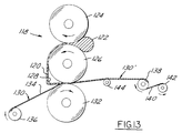
- Fig. 13 illustrates an apparatus 118 and method for coating with a compounded elastomer a relatively large quantity of a knit fabric.
- a thin sheet 120 of the compounded elastomer is produced by disposing a quantity of the compounded elastomer 122 between a pair of co-rotating cylindrical rollers 124 & 126.
- the sheet 120 is stripped from the roller 126 by a stripper bar 128 and passed along with a web 130 of the knit fabric 86 between the nip of co-rotating cylindrical rollers 126 & 132 to calender the sheet of elastomer onto only one face 134 of the fabric.
- the sheet of elastomer has a nominal thickness of about 0.008 to 0.010 of an inch and the gap between the calendering rollers is adjusted to produce just enough force for the sheet of elastomer to adhere to the fabric.
- the web 130 of fabric is rolled on a reel 136 from which it is unwound as it passes between the calendering rollers.
- the web of coated fabric 130' is wound on a take-up reel 138 along with a polyethelene sheet 140 received on a reel 142 to prevent the layers of uncured elastomer from sticking together.
- the web of coated fabric 130' can be supported on one or more driven rollers 144 disposed between the take-up reel 138 and the calendering rollers.
- the relative speed of the reel 136 unwinding the web 130 of fabric, the calendering rollers 126 & 132, the support roller 144 and the take-up reel 138 can be varied and adjusted within predetermined limits to properly tension the web 130 of fabric for application of the sheet 120 of elastomer thereto by the calendering rollers 126 & 132.
- each side edge is heated to provide a fused strip about 1" wide which is used in winding it on the reel 136, unwinding it, feeding it through the calender rollers, and winding it on the take-up reel 138.
- these strips keep the fabric from necking down when tension is applied to the fabric during the coating process and minimize the stresses in the coated, molded and cured composite material of the finished diaphragms 40.
- the polyethelene sheet 140 has a smooth surface which permits any residual stresses in the coated fabric web 130', due to it having been tensioned, to relax and dissipate before the coated fabric is molded. If desired, rolls of coated fabric 130' with the polyethylene sheet between the layer can be stored for several weeks before molding by refrigerating it at a relatively low temperature of about 30° F. to 40° F. to prevent curing of the compounded elastomer.
- the web of coated fabric 130' can be unrolled and cut into blanks of the appropriate size such as blanks 108, molded and trimmed in the same manner as previously described for blanks 108 to produce completely finished diaphragms 40.
- the resulting diaphragms 40 are about 30% to 50% thicker and yet substantially more flexible than the prior art diaphragms made with a silk fabric.
- the resulting diaphragms have dramatically improved moisture and fuel resistance, durability and in service useful life, improved and more stable properties and dimensions, and are of economical manufacture.
Landscapes
- Engineering & Computer Science (AREA)
- General Engineering & Computer Science (AREA)
- Mechanical Engineering (AREA)
- Chemical & Material Sciences (AREA)
- Combustion & Propulsion (AREA)
- Diaphragms And Bellows (AREA)
- Laminated Bodies (AREA)
- Knitting Of Fabric (AREA)
- Treatments For Attaching Organic Compounds To Fibrous Goods (AREA)
Abstract
Description
- This invention relates to diaphragms and more particularly to an improved diaphragm and method of making diaphragms for carburetors and the like.
- Diaphragm carburetors generally have a flexible diaphragm disposed in a fuel chamber which opens to main and idling jets or orifices. Typically, the diaphragm divides the chamber into a wet chamber side which is supplied with fuel and is subjected to sub-atmospheric pressure during operation of the engine and a dry chamber side which may be subjected to atmospheric pressure. The diaphragm controls a fuel inlet valve disposed between a supply of fuel and the wet chamber side. As the engine draws fuel from the wet chamber side, the quantity of the fuel in the wet chamber will decrease, and the diaphragm will move against the bias of a spring to open the needle valve and allow fuel to enter the chamber.
- In operation, the diaphragm repeatedly opens and closes the inlet needle valve so that fuel can enter the diaphragm chamber in response to sub-atmospheric pressure in the throat of the carburetor. Accordingly, a certain amount of fuel can be maintained in the diaphragm chamber at a substantially constant pressure to supply fuel to the main and idling jets. The diaphragm must be extremely flexible because the valve must open and close rapidly with a small pressure differential which is typically one to two inches of water. It must also operate over a wide temperature range of about -40° F. to 180° F.
- For over 40 years the small engine industry has experienced many problems in the manufacture, in service use, and performance of fuel metering diaphragms. Currently most diaphragms are made of a rubber coated silk material. In use, the performance characteristics of these diaphragms change and deteriorate substantially. The inventors have discovered that the silk fibers absorb moisture from the atmosphere and/or the fuel, resulting in a diaphragm that changes its performance characteristics depending on the ambient weather conditions, such as temperature and humidity, and the moisture content of the fuel which severely limits the performance of the fuel metering diaphragms. Other materials, such as woven nylon, have also been found to be ineffective because they produce a diaphragm which is too thick and/or inflexible to adequately respond to small pressure changes. When in prolonged contact with liquid fuel, the coating also swells or increases in volume and deteriorates in hardness, tensile strength and ultimate elongation.
- Additionally, currently available manufacturing processes are unable to produce diaphragms having the dimensional tolerances and performance characteristics required. A two-ply rubber coating is used with one ply or layer being applied to both sides of a sheet of material from which the diaphragm is cut. This increases the rigidity of the material which, when coupled with the above mentioned problems of the material, results in a diaphragm that in incapable of consistently performing as required.
- Previously, the silk fabric with an uncured rubber coating on both sides was heated in an oven to fully cure the rubber and then cooled to room temperature. Thereafter, a stack or pile of several of the resulting flat composite sheets were placed in a multiple cavity mold and simultaneoulsy molded under a force of 6-20 tons for a 54 cavity mold at a temperature of 330° to 375° F for 4 to 8 minutes to form a bellows or convolution in the diaphragm. Thereafter, the molded sheets were cooled and trimmed in a die and press to cut or blank out the individual diaphragms from each sheet. When in service in a carburetor, the convolution tends to become smaller, diminish or even disappear and thus is not permanent and degrades performance of the diaphragm.
- Since up to four cured two ply rubber coated sheets are molded at the same time to form the bellows, they are subjected to an uneven application of pressure and heat. This results in different performance properties for each diaphragm.
- A fuel metering diaphragm embodying this invention has a warp knit fabric, preferably of polyester, with an elastomer coating applied to only one side of the fabric and disposed in the interstices of the fabric to provide a fuel resistant barrier. The elastomer is applied to only one side of a tensioned sheet of the fabric and one coated sheet at a time is molded under heat and pressure to dispose the elastomer in the interstices of the fabric, vulcanize the coating on the fabric and permanently form the desired contour of the diaphragm.
- Objects, features and advantages of this invention are to provide a diaphragm having greater moisture resistance, enhanced flexibility, improved consistency when mass produced, greatly increased in service useful life, flexibility and tensile strength, and of simple design and economical manufacture and assembly.
- These and other objects, features and advantages of this invention will be apparent from the following detailed description, appended claims and accompanying drawings in which:
- FIG. 1 is an an end view of a carburetor assembly;
- FIG. 2 is a side view of the carburetor assembly;
- FIG. 3 is a view taken along line 3-3 in FIG. 1;
- FIG. 4 is a top view of a diaphragm of the presesnt invention with a cutaway portion showing the tricot knit fabric;
- FIG. 5 is a sectional view taken along line 5-5 of FIG. 4;
- FIG. 6 is an end view of the tricot knit fabric stretched over a frame;
- FIG. 7 is a fragmentary and enlarged top view of the fabric showing the warp knit polyester fibers;
- FIG. 8 is an end view of the stretched fabric with the elastomer coating being applied with a doctor blade;
- FIG. 9 is an end view of a heater assembly for the composite fabric and coating;
- FIG. 10 is an end view of a press and mold assembly;
- FIG. 11 is an enlarged and fragmentary cross section of the fabric with the elastomer coating applied to only one side and cured;
- FIG. 12 is an end view of a trimming and cutting die and press; and
- FIG. 13 is a semi-diagrammatic drawing of a preferred apparatus for applying an elastomer coating to only one side of the fabric in large volume production.
- As illustrated in FIGS. 1-3, a conventional fuel pump and
carburetor 20 for a two cycle small engine has amain body 22 with amixing passage 24 in which athrottle valve 26 is mounted upon ashaft 28 controlled by alever 30. A fuel pump 32 in the body receives fuel from afuel inlet 34 and delivers it to acarburetor diaphragm chamber 36 through a diaphragm controlledinlet valve 38 in a conventional circuit including the fuel pump, the inlet valve, and afuel metering diaphragm 40 embodying this invention. The carburetor is attached to the engine throughmounting holes 42. -
Small passages 44 opening into the mounting face of the carburetor (FIG. 2) receive engine crankcase pressure pulses for actuating a diaphragm 46 of the fuel pump received on the top of the carburetor body under a top plate orhousing cap 47. - Referring to FIG. 3, in use, the pump 32 delivers fuel to the
metering valve assembly 38 through achamber 50 with afilter screen 52 therein and apassage 54 terminating at avalve seat 56. The valve assembly has aneedle valve 58 which is actuated by alever arm 60 connected at oneend 62 to the valve, fulcrumed between its ends at 64 and having a control finger 66 actuated at its free end by thediaphragm 40. The diaphragm in cooperation with the body defines afuel chamber 68 and in cooperation with acover plate 69 defines a dry orair chamber 70 communicating with the atmosphere. Theneedle valve 58 is yieldably urged to its closed position bearing on theseat 56 by acoil spring 72 and is actuated to an open position by movement of thediaphragm 40. The coil spring is received in apocket 73 in the body and bears on the finger 66 of the lever arm. - Preferably, the diaphragm has a
backing disc 74, and a plunger 76 with a shank extending through the disc, the diaphragm and awasher 78 which are staked together in assembled relationship. Fuel inchamber 68 is supplied to amain metering jet 80 andidle jets 82 through passages (not shown) communicating with thefuel chamber 68. If desired, needle valve assemblies 84 (only one of which is shown), can be provided to adjust the quantity of fuel supplied to the main jet and the idle jets. - In use, as fuel is drawn from the
chamber 68, the quantity of fuel therein will decrease and the differential pressure on the diaphragm will move thelever arm 60 against the bias of thespring 72 in a counter-clockwise direction (as viewed in FIG. 3), to open thevalve 58 to allow fuel to enter thechamber 68. As the chamber fills with additional fuel, the diaphragm will tend to move the lever arm clockwise and close the needle valve to thereby regulate the pressure of the fuel within the chamber. When the engine is under load, and particularly when operating at full throttle, fuel flows rapidly into the chamber which causes the diaphragm to cycle or fluctuate quite rapidly. Thus, for the carburetor to function properly under a large variety of operating conditons, it is necessary that the diaphragm be very flexible and yet still be relatively strong and impervious to liquid fuel and not deteriorate in use due to repeated flexing and contact with the liquid fuel. - The
diaphragm 40 of the present invention, as seen in FIGS. 4 and 5, comprises a thin sheet ofknit fabric 86 preferably of polyester which has been coated on only one side (preferably thefuel chamber 68 side) with anelastomer 88 and molded to form atypical bellows 90 with a convolute shape. Desirably, a sealinggasket 89 is attached to the fabric adjacent its periphery and outside of the convolution. - One feature of the present invention is that the
fabric 86 is preferably a warp knit fabric. A knit fabric is composed of a series of interconnecting loops which may be prepared in its simplest form from a single yarn. By means of a needle, a loop is formed in ayarn 91 and is cast off when the needle draws a second loop through the first loop. The process is then repeated, to form a chain of loops interconnecting with adjacent chains to form a fabric. FIG. 7 shows the basic structure of thewarp knit fabric 86 with interconnecting loops ofyarn 91 withinterstices 92 between the yarn. As viewed in FIG. 7, the lines of loops running left to right are called "courses"; and those running from top to bottom are called "wales". - The
knit fabric 86 is a plain warp knit fabric preferably of polyester fibers. Warp knit and weft knit are the basic types of knit fabrics. Warp-knit fabrics are manufactured by passing each end of the fibers through its own needle forming a loop which intersects with adjacent loops. Most warp-knits are made on a tricot machine, as is known in the knitting industry. The resulting fabric is one of a tight weave having great strength, flexibility and moisture resistance. - Preferably, the fabric is a tricot warp knit fabric of Dacron® polyester fibers and has a nominal thickness of 0.004 to 0.010 and preferably 0.005 to 0.007 of an inch as determined by American Society for Testing Materials (ASTM) procedure D-1777, a weight of 0.5 to 3.0, desirably 0.6 to 1.0, and preferably about 0.75 ounces per square yard as determined by ASTM procedure D-3776 with the courses having 36 to 58, and preferably 46 threads per inch, and the wales having 30 to 40 and preferably 34 threads per inch, as determined by ASTM procedure D-3887. Preferably, this fabric has a transverse break strength of 10 to 20 pounds and a longitudinal break strength of 15 to 25 pounds as determined by the grab test method of ASTM procedure D-5034. Preferably, the fabric has a Mullen burst strength of 45 to 75 psi as determined by ASTM procedure D-3786. Preferably, the threads of the fabric have a maximum denier of 20.
- The tricot knit polyester fabric is coated on only one side with an elastomeric polymer, which is preferably a polyacrylonitrile butadiene rubber (NBR). Preferably, this polymer is a medium acrylonitrile butadiene copolymer that is compounded with various solvents, accelerators, nucleating agents, vulcanizing agents, plasticizers, release agents, etc., to optimize fuel resistance and flexibility. Preferably, the compounded NBR has a Money viscosity of 40 to 60, hardness on the Shore A scale of 30 to 40 points under ASTM procedure D-2240, and under ASTM procedure D-412, a tensile strength of at least 1500 psi, an ultimate elongation of at least 800% and a Young's modulus of elasticity of at least 80 psi at 100% elongation.
- Vulcanized samples of the compounded NBR after being soaked in the specified fuel at room temperature for seventy hours preferably have the following properties:
Property ASTM Test Procedure ASTM D471 Reference Fuel B C Maximum Hardness Decrease in PTS D2240 10 10 Maximum Tensile Strength Decrease in % D412 60 80 Maximum Ultimate Elongation Decrease in % D412 35 50 Maximum Volume Increase in % D471 20 35 Maximum Dryout Volume decrease in % D471 15 20 - Other suitable materials are fabrics with warp knit synthetic fibers with high moisture resistance such as fibers of polyaramid or polyamide (Nylon) having similar physical properties to the preferred polyester tricot knit fabric and elastomeric polymer coatings of fluorosilicones or low temperature fluoroplastics or fluorocarbons (Viton® GFLT).
- The knit fabric is coated on only one side with the elastomeric polymer. While being coated, preferably the fabric is tensioned or stretched to a taut and generally planar condition. To facilitate tensioning the fabric, preferably about one inch of the material on each side is heated and fused to provide strips along the side edges for feeding and handling the fabric. This keeps the material from "necking down" when tension is applied to the fabric during the coating process and produces a relatively stress-free finished composite membrane material for molding.
- When a relatively small quantity of coated fabric is produced, a
piece 94 offabric 86 may be tensioned or stretched to a taut and generally planar condition, as shown in Fig. 6, by stretching it over acarrier frame 96 and wrapping the ends of the piece about the frame. After a piece of fabric is tensioned and framed, a coat orthin layer 98 of the compounded elastomer is applied to one side, preferably by using adoctor blade 100 as shown in Fig. 8 to produce a composite sheet ormembrane 102. The elastomer is applied relatively uniformly over only one surface or face 104 of the fabric. In applying the compounded elastomer, only sufficient force is used to insure that the elastomer adheres to the fabric. Preferably, the wetting of the fabric by the elastomer is minimized so that the courses and wales of the fabric will not be adhesively "locked up" which reduces the overall flexibility of the finished composite membrane. The fabric, not the elastomer, is believed to be the primary contributor to the flexibility of the molded diaphragm. After coating and before vulcanizing, the coated composite fabric preferably has a nominal thickness of about 0.012 to 0.018 of an inch. - To facilitate further handling, preferably before molding, the elastomer is allowed to develop a tacky condition by partially drying or slightly curing it, which may be accomplished by exposure at room temperature or if desired by heating to an elevated temperature the
composite sheet 102. The composite sheet may be preheated by placing it in an oven 106, as shown in Fig. 9, for about 5 to 20 minutes with an oven air temperature of about 150° F. to 200° F. - Thereafter, the
coated sheet 102 is removed from the carrier frame, dusted with a conventional mold releasing agent, and cut intoblanks 108 of the appropriate size for the mold. For a mold 110 having 36 cavities laid out in a generally square (6 x 6) arrangement, these blanks are typically about 10" x 10". - As shown in Fig. 10, one blank 108 at a time is placed in the open mold 110 which is closed by a
press 112 to apply pressure and heat to the composite blank to force the elastomer into theinterstices 92 between the fibers of the knit fabric, to cure the elastomer and to produce the bellows or convolute shape in thefinished diaphragm 40. The mold is preheated to about 310° to 370° F. and preferably to 340° F. to 360° F. The composite blank has a residence time in the closed mold of about 3 to 4-1/2 minutes and preferably 3-1/4 to 3-3/4 minutes, while being subjected to a molding force of 10 to 15 tons or about 220 to 330 pounds per square inch of the area of one face of the composite blank received in the mold. Preferably, to permit gases to escape from the mold, it is vented or it may be periodically rapidly slightly opened and then closed several times during the molding cycle. - This molding forces the elastomer on one side through the
interstices 92 of the fabric to the opposite side of the fabric and results in the molded composite sheet 108' of the fabric having an elastomeric coating which is only one-ply deep but substantially covers the fibers on both sides of the fabric. Typically, after the molding is completed, the sheet 108' of molded diaphragms has a nominal thickness of about 0.007 to 0.010 of an inch. - The sheets 108' of molded diaphragms are cooled to room temperature and then cut and trimmed in a die 114 (Fig. 12) received in a
reciprocating press 116 which cuts theindividual diaphragms 40 from a single molded sheet 108' at a time. The individual finished diaphragms may then be packaged for shipment, installation and use. - Desirably, but not necesarily, the sealing
gaskets 89 are bonded to the coated blank 108 during the molding operation. Individual gaskets may be die cut from a sheet of high density cellulose fiber reinforced material coated on one side with a suitable bonding agent or adhesive. The gaskets are placed in the mold on the blank 108 preferably with the adhesive facing the fabric side of the blank. The gaskets may be located in the mold with suitable locating pins projecting into the bolt mounting holes through each gasket. A suitable cellulose gasket material is commercially available as NV-512 from Specialty Paperboard, Inc. of Beaver Falls, New York 13305. A suitable vulcanizable bonding agent is commercially available as Thixon® OSN-2 from Whittaker, Dayton Chemicals Division, P.O. Box 127, West Alexandria, Ohio 45381. - Fig. 13 illustrates an
apparatus 118 and method for coating with a compounded elastomer a relatively large quantity of a knit fabric. Athin sheet 120 of the compounded elastomer is produced by disposing a quantity of the compoundedelastomer 122 between a pair of co-rotatingcylindrical rollers 124 & 126. Thesheet 120 is stripped from theroller 126 by astripper bar 128 and passed along with aweb 130 of theknit fabric 86 between the nip of co-rotatingcylindrical rollers 126 & 132 to calender the sheet of elastomer onto only oneface 134 of the fabric. Typically, the sheet of elastomer has a nominal thickness of about 0.008 to 0.010 of an inch and the gap between the calendering rollers is adjusted to produce just enough force for the sheet of elastomer to adhere to the fabric. Theweb 130 of fabric is rolled on areel 136 from which it is unwound as it passes between the calendering rollers. - The web of coated fabric 130' is wound on a take-up
reel 138 along with apolyethelene sheet 140 received on areel 142 to prevent the layers of uncured elastomer from sticking together. If desired, the web of coated fabric 130' can be supported on one or more drivenrollers 144 disposed between the take-upreel 138 and the calendering rollers. The relative speed of thereel 136 unwinding theweb 130 of fabric, the calenderingrollers 126 & 132, thesupport roller 144 and the take-upreel 138 can be varied and adjusted within predetermined limits to properly tension theweb 130 of fabric for application of thesheet 120 of elastomer thereto by the calenderingrollers 126 & 132. - To facilitate substantially uniform tensioning of the
web 130 of fabric, preferably each side edge is heated to provide a fused strip about 1" wide which is used in winding it on thereel 136, unwinding it, feeding it through the calender rollers, and winding it on the take-upreel 138. As previously indicated, these strips keep the fabric from necking down when tension is applied to the fabric during the coating process and minimize the stresses in the coated, molded and cured composite material of thefinished diaphragms 40. - Preferably, the
polyethelene sheet 140 has a smooth surface which permits any residual stresses in the coated fabric web 130', due to it having been tensioned, to relax and dissipate before the coated fabric is molded. If desired, rolls of coated fabric 130' with the polyethylene sheet between the layer can be stored for several weeks before molding by refrigerating it at a relatively low temperature of about 30° F. to 40° F. to prevent curing of the compounded elastomer. - When desired, the web of coated fabric 130' can be unrolled and cut into blanks of the appropriate size such as
blanks 108, molded and trimmed in the same manner as previously described forblanks 108 to produce completelyfinished diaphragms 40. - The resulting
diaphragms 40 are about 30% to 50% thicker and yet substantially more flexible than the prior art diaphragms made with a silk fabric. The resulting diaphragms have dramatically improved moisture and fuel resistance, durability and in service useful life, improved and more stable properties and dimensions, and are of economical manufacture.
Claims (15)
- A synthetic composite fuel diaphragm for use in a carburetor having a least one side subject to contact with a liquid fuel, said diaphragm comprising: a fabric of warp knitted synthetic fibers with interstices therebetween, and an elastomeric polymer coating applied to only one side of the fabric, disposed in the interstices and cured to provide a barrier at least substantially impervious to liquid fuel.
- A synthetic composite fuel diaphragm as defined in claim 1 wherein said elastomeric polymer coating is a polyacrylonitrile butadine rubber.
- A synthetic composite fuel diaphragm as defined in claim 1 wherein said one side of the diaphragm with said elastomeric polymer coating applied thereon is subject to contact with liquid fuel.
- A synthetic composite fuel diaphragm as defined in claim 1 wherein said elastomeric polymer extends from said one side of the diaphragm through the interstices to the opposite side thereof.
- A synthetic composite fuel diaphragm as defined in claim 1 wherein said synthetic fibers of the knit fabric are polyester fibers.
- A synthetic composite fuel diaphragm as defined in claim 1 wherein said synthetic fibers of the knit fabric are selected from the group consisting essentially of at least one of polyester, polyamide, polyaramide fibers and blends thereof.
- A synthetic composite fuel diaphragm as defined in claim 1 wherein said elastomeric polymer coating consists essentially of at least one of acrylonitrile butadine, fluorosilicone and fluorocarbon polymers.
- A synthetic composite fuel diaphragm as defined in claim 1 wherein said fabric has a nominal thickness not greater than about 0.010 of an inch as determined per ASTM procedure D-1777.
- A synthetic composite fuel diaphragm as defined in claim 1 wherein said diaphragm has a nominal thickness not greater than about 0.010 of an inch.
- A method of making a synthetic composite fuel diaphragm comprising the steps of:
providing a sheet of a fabric of warp knitted synthetic fibers having interstices therebetween,
tensioning the sheet into a substantially taut condition,
applying a layer of an elastomeric polymer to only one side of the sheet,
placing the coated sheet into a mold,
while in the mold applying heat and pressure to the coated sheet to force the elastomeric polymer into the interstices of the fabric, mold the diaphragm and cure the elastomer, and
removing the molded diaphragm from the mold. - The method defined in claim 10 further comprising the step of partially curing the elastomer to a tacky condition before molding.
- The method defined in claim 11 wherein the tacky condition is produced by the step of heating the sheet to an elevated temperature for a suffiient period of time to partially cure the elastomer.
- The method defined in claim 10 wherein the fabric has a nominal thickness not greater than about 0.010 of an inch as determined per ASTM procedure D-1777.
- The method defined in claim 10 wherein the molded diaphragm has a nominal thickness not greater than about 0.010 of an inch.
- The method of claim 10 further comprising the step of fusing together the fibers of the fabric in a longitudinally extending strip at each side edge of the sheet of fabric before the step of tensioning the sheet of fabric.
Applications Claiming Priority (2)
| Application Number | Priority Date | Filing Date | Title |
|---|---|---|---|
| US9558 | 1993-01-26 | ||
| US08/009,558 US5262092A (en) | 1993-01-26 | 1993-01-26 | Synthetic composite fuel metering membrane |
Publications (2)
| Publication Number | Publication Date |
|---|---|
| EP0608490A1 true EP0608490A1 (en) | 1994-08-03 |
| EP0608490B1 EP0608490B1 (en) | 1998-08-12 |
Family
ID=21738400
Family Applications (1)
| Application Number | Title | Priority Date | Filing Date |
|---|---|---|---|
| EP93117104A Expired - Lifetime EP0608490B1 (en) | 1993-01-26 | 1993-10-21 | Synthetic composite fuel metering membrane |
Country Status (4)
| Country | Link |
|---|---|
| US (2) | US5262092A (en) |
| EP (1) | EP0608490B1 (en) |
| JP (1) | JPH0735238A (en) |
| DE (1) | DE69320319T2 (en) |
Cited By (2)
| Publication number | Priority date | Publication date | Assignee | Title |
|---|---|---|---|---|
| US10233870B2 (en) | 2014-07-21 | 2019-03-19 | Dätwyler Schweiz Ag | Control diaphragm for diaphragm carburetors |
| US10830184B2 (en) | 2016-01-11 | 2020-11-10 | Dätwyler Schweiz Ag | Control diaphragm for diaphragm carburetor |
Families Citing this family (34)
| Publication number | Priority date | Publication date | Assignee | Title |
|---|---|---|---|---|
| US6193914B1 (en) | 1995-11-30 | 2001-02-27 | Ubertech Texas, Inc. | Molding thermosetting polymers onto substrates |
| US5914082A (en) * | 1995-11-30 | 1999-06-22 | Harrison; Donald G. | Method and apparatus for molding thermosetting polymers onto substrates |
| US6241930B1 (en) | 1995-11-30 | 2001-06-05 | Ubertech Texas, Inc. | Method of constructing a garment with a graphical design thereon |
| US5928593A (en) * | 1995-11-30 | 1999-07-27 | Harrison; Donald G. | Method and apparatus for molding thermosetting polymers onto substrates |
| US5939004A (en) * | 1995-11-30 | 1999-08-17 | Harrison; Donald G. | Molding thermosetting polymers onto substrates |
| US6139787A (en) | 1996-10-24 | 2000-10-31 | Ubertech Texas, Inc. | Method for applying molded silicone design elements onto substrates |
| GB9722578D0 (en) * | 1997-10-24 | 1997-12-24 | Protec Health International Li | Impregnated fabrics |
| US6123322A (en) * | 1998-06-16 | 2000-09-26 | Walbro Corporation | Single screw carburetor |
| US6135429A (en) * | 1998-11-04 | 2000-10-24 | Walbro Corporation | Carburetor with automatic fuel enrichment |
| GB2396841B (en) * | 2000-03-17 | 2004-09-08 | Walk Off Mats Ltd | Mat,and method of manufacturing a mat |
| US6402125B1 (en) * | 2000-03-29 | 2002-06-11 | Walbro Corporation | Carburetor valve rotational setting retainer assembly |
| US6402124B1 (en) | 2000-03-29 | 2002-06-11 | Walbro Corporation | Carburetor fuel mixture adjustment assembly |
| US6302384B1 (en) | 2000-06-01 | 2001-10-16 | Walbro Corporation | Needle valve carburetor |
| US6715737B2 (en) | 2000-08-29 | 2004-04-06 | Walbro Corporation | Fuel metering system for a carburetor |
| US6454246B1 (en) | 2000-11-17 | 2002-09-24 | Walbro Corporation | Carburetor with separate nozzle post member |
| US6523809B2 (en) | 2001-03-22 | 2003-02-25 | Walbro Corporation | Carburetor with fuel enrichment |
| US6622992B2 (en) | 2001-03-22 | 2003-09-23 | Walbro Corporation | Carburetor with fuel enrichment |
| US20050040547A1 (en) * | 2002-07-11 | 2005-02-24 | Walbro Engine Management, L.L.C. | Carburetor air-fuel mixture adjustment assembly |
| US7070173B2 (en) * | 2002-07-11 | 2006-07-04 | Walbro Engine Management, L.L.C. | Carburetor air-fuel mixture adjustment assembly |
| US20040007788A1 (en) * | 2002-07-11 | 2004-01-15 | Giovanni Vimercati | Carburetor air-fuel mixture adjustment assembly |
| US7287742B2 (en) * | 2003-04-03 | 2007-10-30 | Walbro Engine Management, L.L.C. | Carburetor and method of manufacturing |
| US20040195705A1 (en) * | 2003-04-03 | 2004-10-07 | Burns Michael P. | Carburetor |
| DE102004047720A1 (en) * | 2003-11-03 | 2005-04-21 | Trelleborg Sealing Solutions U | Elastomeric membrane fabrication involves forming mixture of elastomer and dispersed fibres, supplying mixture to mold, and press molding |
| DE102004031335B4 (en) * | 2004-06-29 | 2009-12-03 | Contitech Elastomer-Beschichtungen Gmbh | Process for producing a molding membrane |
| DE102005005621B4 (en) * | 2005-02-08 | 2009-01-08 | Hübner GmbH | Bellows a transition between two articulated vehicles or bellows of a passenger boarding bridge |
| US7699294B2 (en) * | 2007-04-20 | 2010-04-20 | Walbro Engine Management, L.L.C. | Charge forming device with idle and open throttle choke control |
| US20090057600A1 (en) * | 2007-08-29 | 2009-03-05 | Ckd Corporation | Vacuum opening/closing valve |
| US8747582B2 (en) * | 2008-09-05 | 2014-06-10 | Federal-Mogul Powertrain, Inc. | Self-wrapping textile sleeve with protective coating and method of construction thereof |
| EP2607737B1 (en) * | 2010-08-17 | 2020-01-15 | Fujikura Composites Inc. | Diaphragm for vehicle brake |
| CN104641097B (en) * | 2012-07-25 | 2018-02-13 | 沃尔布罗发动机使用有限责任公司 | Layered membranes |
| US10054082B2 (en) | 2015-10-20 | 2018-08-21 | Walbro Llc | Carburetor with fuel metering diaphragm |
| CN107187077A (en) * | 2017-07-06 | 2017-09-22 | 哈尔滨理工大学 | A kind of fiber reinforcement barrier film and moulding process for being used to seal skirt pile sleeve |
| US10774936B2 (en) * | 2017-12-07 | 2020-09-15 | Sed Flow Control Gmbh | Diaphragm for a diaphragm valve and method for the manufacture of the diaphragm |
| US11118536B2 (en) | 2018-12-17 | 2021-09-14 | Walbro Llc | Tamper resistant adjustment valve for a charge forming device |
Citations (9)
| Publication number | Priority date | Publication date | Assignee | Title |
|---|---|---|---|---|
| US2734009A (en) * | 1956-02-07 | coffey | ||
| US2779687A (en) * | 1951-08-20 | 1957-01-29 | Gen Motors Corp | Fuel pump diaphragm and process for making same |
| GB916050A (en) * | 1960-06-14 | 1963-01-16 | J & A Hillman Ltd | Improvements in or relating to fluid impervious diaphragms |
| JPS58131468A (en) * | 1982-01-30 | 1983-08-05 | Toyoda Gosei Co Ltd | Diaphragm |
| JPS6120738A (en) * | 1984-07-09 | 1986-01-29 | 興國ゴム工業株式会社 | Diaphragm |
| JPS62179937A (en) * | 1986-02-04 | 1987-08-07 | 薄井 忠 | Laminated rubber cloth |
| JPH01177447A (en) * | 1987-12-27 | 1989-07-13 | Toyoda Gosei Co Ltd | Diaphragm |
| JPH01210661A (en) * | 1988-02-18 | 1989-08-24 | Toyoda Gosei Co Ltd | Manufacture of diaphragm |
| JPH04321877A (en) * | 1991-04-22 | 1992-11-11 | Toyoda Gosei Co Ltd | Diaphragm |
Family Cites Families (22)
| Publication number | Priority date | Publication date | Assignee | Title |
|---|---|---|---|---|
| US2444394A (en) * | 1943-03-11 | 1948-06-29 | Lane Wells Co | Method of molding diaphragms |
| US2642090A (en) * | 1946-11-16 | 1953-06-16 | Niles Bement Pond Co | Diaphragm assembly and method of making same |
| US2595127A (en) * | 1946-12-09 | 1952-04-29 | Carter Carburetor Corp | Method of forming diaphragms |
| GB717602A (en) * | 1952-02-06 | 1954-10-27 | Ici Ltd | Improvements in or relating to coated sheet material |
| US3032462A (en) * | 1955-11-04 | 1962-05-01 | Scott Aviation Corp | Process of making a diaphragm |
| US2998343A (en) * | 1958-01-02 | 1961-08-29 | Gen Motors Corp | Process for making a hydraulic diaphragm |
| US3045605A (en) * | 1958-09-15 | 1962-07-24 | Tillotson Mfg Co | Fuel feeding means |
| US3104617A (en) * | 1960-08-08 | 1963-09-24 | Mcculloch Corp | Diaphragm pump |
| US3502530A (en) * | 1966-01-14 | 1970-03-24 | Clupak Inc | Method of producing a finished reinforced edge on flexible webs or sheets |
| US3523857A (en) * | 1967-04-21 | 1970-08-11 | Chem Rubber Products Inc | Diaphragm assembly |
| US3601102A (en) * | 1970-01-16 | 1971-08-24 | Walbro Corp | Vibration-responsive fuel supplement valve |
| US3633557A (en) * | 1970-01-30 | 1972-01-11 | Wallro Corp | Diaphragm carburetor |
| JPS5944988B2 (en) * | 1980-06-19 | 1984-11-02 | 横浜ゴム株式会社 | Cracks prevention tape |
| US4349593A (en) * | 1981-04-06 | 1982-09-14 | Penn-Gil Fabrics, Inc. | Double knit fabric processing into decorative goods |
| JPS6021434Y2 (en) * | 1982-10-28 | 1985-06-26 | ヤマト化学工業株式会社 | Synthetic resin leather for automobiles |
| JPS60229726A (en) * | 1984-04-28 | 1985-11-15 | Toyoda Gosei Co Ltd | Die for extrusion of sheet |
| US4615934A (en) * | 1985-11-22 | 1986-10-07 | Peabody Abc Corporation | Warp knit weft insertion fabric and plastic sheet reinforced therewith |
| US4868038A (en) * | 1987-10-23 | 1989-09-19 | The Dow Chemical Company | Carbonaceous fiber reinforced composites |
| US4828909A (en) * | 1987-12-17 | 1989-05-09 | Highland Industries, Inc. | Elastomer-coated fabric products and process for producing the same |
| US5093067A (en) * | 1988-03-14 | 1992-03-03 | Allied-Signal Inc. | Injection molding of fabric reinforced elastomeric diaphragms |
| US4994225A (en) * | 1988-06-28 | 1991-02-19 | Uniroyal Plastics Company, Inc. | Production of passive restraint device |
| JPH0337062A (en) * | 1989-07-03 | 1991-02-18 | Nitta Gelatin Inc | Manufacture of disposable product |
-
1993
- 1993-01-26 US US08/009,558 patent/US5262092A/en not_active Expired - Fee Related
- 1993-10-21 EP EP93117104A patent/EP0608490B1/en not_active Expired - Lifetime
- 1993-10-21 DE DE69320319T patent/DE69320319T2/en not_active Expired - Fee Related
- 1993-10-29 JP JP5271471A patent/JPH0735238A/en active Pending
-
1995
- 1995-02-16 US US08/390,810 patent/US5487861A/en not_active Expired - Fee Related
Patent Citations (9)
| Publication number | Priority date | Publication date | Assignee | Title |
|---|---|---|---|---|
| US2734009A (en) * | 1956-02-07 | coffey | ||
| US2779687A (en) * | 1951-08-20 | 1957-01-29 | Gen Motors Corp | Fuel pump diaphragm and process for making same |
| GB916050A (en) * | 1960-06-14 | 1963-01-16 | J & A Hillman Ltd | Improvements in or relating to fluid impervious diaphragms |
| JPS58131468A (en) * | 1982-01-30 | 1983-08-05 | Toyoda Gosei Co Ltd | Diaphragm |
| JPS6120738A (en) * | 1984-07-09 | 1986-01-29 | 興國ゴム工業株式会社 | Diaphragm |
| JPS62179937A (en) * | 1986-02-04 | 1987-08-07 | 薄井 忠 | Laminated rubber cloth |
| JPH01177447A (en) * | 1987-12-27 | 1989-07-13 | Toyoda Gosei Co Ltd | Diaphragm |
| JPH01210661A (en) * | 1988-02-18 | 1989-08-24 | Toyoda Gosei Co Ltd | Manufacture of diaphragm |
| JPH04321877A (en) * | 1991-04-22 | 1992-11-11 | Toyoda Gosei Co Ltd | Diaphragm |
Non-Patent Citations (6)
| Title |
|---|
| DATABASE WPI Section Ch Week 8611, Derwent World Patents Index; AN 86-071841 * |
| DATABASE WPI Section Ch Week 8737, Derwent World Patents Index; AN 87-260390 * |
| PATENT ABSTRACTS OF JAPAN vol. 13, no. 455 (M - 879) 13 October 1989 (1989-10-13) * |
| PATENT ABSTRACTS OF JAPAN vol. 13, no. 521 (M - 896) 21 November 1989 (1989-11-21) * |
| PATENT ABSTRACTS OF JAPAN vol. 17, no. 151 (M - 1387) 25 March 1993 (1993-03-25) * |
| PATENT ABSTRACTS OF JAPAN vol. 7, no. 244 (M - 252) 28 October 1983 (1983-10-28) * |
Cited By (2)
| Publication number | Priority date | Publication date | Assignee | Title |
|---|---|---|---|---|
| US10233870B2 (en) | 2014-07-21 | 2019-03-19 | Dätwyler Schweiz Ag | Control diaphragm for diaphragm carburetors |
| US10830184B2 (en) | 2016-01-11 | 2020-11-10 | Dätwyler Schweiz Ag | Control diaphragm for diaphragm carburetor |
Also Published As
| Publication number | Publication date |
|---|---|
| US5487861A (en) | 1996-01-30 |
| DE69320319D1 (en) | 1998-09-17 |
| EP0608490B1 (en) | 1998-08-12 |
| DE69320319T2 (en) | 1999-03-18 |
| US5262092A (en) | 1993-11-16 |
| JPH0735238A (en) | 1995-02-07 |
Similar Documents
| Publication | Publication Date | Title |
|---|---|---|
| EP0608490B1 (en) | Synthetic composite fuel metering membrane | |
| EP0479591B1 (en) | Printing blanket containing a high elongate fabric | |
| US4042743A (en) | Compressible offset printing blanket | |
| JP3616372B2 (en) | Power transmission belt | |
| US4770928A (en) | Method of curing a compressible printing blanket and a compressible printing blanket produced thereby | |
| EP0191779B2 (en) | Method of making a compressible printing blanket and a compressible printing blanket produced thereby | |
| US20060191658A1 (en) | Papermaking belt and method of manufacturing papermaking belt | |
| EP0660760B1 (en) | Printing blanket having improved dynamic thickness stability | |
| EP0714757B1 (en) | Marking material for a power transmission belt/belt sleeve and method of making a power transmission belt/belt sleeve using the marking material | |
| US6308624B1 (en) | Method of producing a compressible layer for a printing blanket | |
| US20070119320A1 (en) | Printing blanket having improved dynamic thickness stability | |
| EP1810837B1 (en) | Printing rubber blanket | |
| EP1195263B1 (en) | A method for manufacturing a blanket for printing | |
| CA2562847A1 (en) | Composite packing material for use in offset lithography and method of making | |
| EP0342286B2 (en) | Method of curing a compressible printing blanket and a compressible printing blanket produced thereby | |
| US3130670A (en) | Printing plate | |
| JP4063934B2 (en) | Belt vulcanization method and belt sleeve manufacturing method | |
| JP2008265031A (en) | Manufacturing method for transmission belt | |
| JPS55159317A (en) | Masking roll and its manufacture | |
| JPH10323914A (en) | Manufacture of cogged belt and mold to be used therefor | |
| JPH0566860B2 (en) | ||
| JP2009051105A (en) | Rubberized cloth molding method, diaphragm manufacturing method | |
| JPH10258465A (en) | Method of manufacturing power transmission belt |
Legal Events
| Date | Code | Title | Description |
|---|---|---|---|
| PUAI | Public reference made under article 153(3) epc to a published international application that has entered the european phase |
Free format text: ORIGINAL CODE: 0009012 |
|
| AK | Designated contracting states |
Kind code of ref document: A1 Designated state(s): DE GB IT SE |
|
| 17P | Request for examination filed |
Effective date: 19950119 |
|
| 17Q | First examination report despatched |
Effective date: 19960725 |
|
| GRAG | Despatch of communication of intention to grant |
Free format text: ORIGINAL CODE: EPIDOS AGRA |
|
| GRAG | Despatch of communication of intention to grant |
Free format text: ORIGINAL CODE: EPIDOS AGRA |
|
| GRAH | Despatch of communication of intention to grant a patent |
Free format text: ORIGINAL CODE: EPIDOS IGRA |
|
| GRAH | Despatch of communication of intention to grant a patent |
Free format text: ORIGINAL CODE: EPIDOS IGRA |
|
| GRAA | (expected) grant |
Free format text: ORIGINAL CODE: 0009210 |
|
| ITF | It: translation for a ep patent filed | ||
| AK | Designated contracting states |
Kind code of ref document: B1 Designated state(s): DE GB IT SE |
|
| REF | Corresponds to: |
Ref document number: 69320319 Country of ref document: DE Date of ref document: 19980917 |
|
| PLBE | No opposition filed within time limit |
Free format text: ORIGINAL CODE: 0009261 |
|
| STAA | Information on the status of an ep patent application or granted ep patent |
Free format text: STATUS: NO OPPOSITION FILED WITHIN TIME LIMIT |
|
| 26N | No opposition filed | ||
| PGFP | Annual fee paid to national office [announced via postgrant information from national office to epo] |
Ref country code: GB Payment date: 19991001 Year of fee payment: 7 |
|
| PGFP | Annual fee paid to national office [announced via postgrant information from national office to epo] |
Ref country code: SE Payment date: 20001003 Year of fee payment: 8 Ref country code: DE Payment date: 20001003 Year of fee payment: 8 |
|
| PG25 | Lapsed in a contracting state [announced via postgrant information from national office to epo] |
Ref country code: GB Free format text: LAPSE BECAUSE OF NON-PAYMENT OF DUE FEES Effective date: 20001021 |
|
| GBPC | Gb: european patent ceased through non-payment of renewal fee |
Effective date: 20001021 |
|
| PG25 | Lapsed in a contracting state [announced via postgrant information from national office to epo] |
Ref country code: SE Free format text: LAPSE BECAUSE OF NON-PAYMENT OF DUE FEES Effective date: 20011022 |
|
| EUG | Se: european patent has lapsed |
Ref document number: 93117104.5 |
|
| PG25 | Lapsed in a contracting state [announced via postgrant information from national office to epo] |
Ref country code: DE Free format text: LAPSE BECAUSE OF NON-PAYMENT OF DUE FEES Effective date: 20020702 |
|
| PG25 | Lapsed in a contracting state [announced via postgrant information from national office to epo] |
Ref country code: IT Free format text: LAPSE BECAUSE OF NON-PAYMENT OF DUE FEES;WARNING: LAPSES OF ITALIAN PATENTS WITH EFFECTIVE DATE BEFORE 2007 MAY HAVE OCCURRED AT ANY TIME BEFORE 2007. THE CORRECT EFFECTIVE DATE MAY BE DIFFERENT FROM THE ONE RECORDED. Effective date: 20051021 |