EP0608408B1 - Welding process for a battery pack - Google Patents
Welding process for a battery pack Download PDFInfo
- Publication number
- EP0608408B1 EP0608408B1 EP93918699A EP93918699A EP0608408B1 EP 0608408 B1 EP0608408 B1 EP 0608408B1 EP 93918699 A EP93918699 A EP 93918699A EP 93918699 A EP93918699 A EP 93918699A EP 0608408 B1 EP0608408 B1 EP 0608408B1
- Authority
- EP
- European Patent Office
- Prior art keywords
- welding
- power
- electrodes
- phase
- battery pack
- Prior art date
- Legal status (The legal status is an assumption and is not a legal conclusion. Google has not performed a legal analysis and makes no representation as to the accuracy of the status listed.)
- Expired - Lifetime
Links
- 238000003466 welding Methods 0.000 title claims abstract description 39
- 238000000034 method Methods 0.000 title claims description 18
- 239000002184 metal Substances 0.000 claims abstract description 6
- 230000005012 migration Effects 0.000 abstract description 3
- 238000013508 migration Methods 0.000 abstract description 3
- 239000000463 material Substances 0.000 abstract description 2
- 239000002826 coolant Substances 0.000 description 2
- 238000001816 cooling Methods 0.000 description 2
- 238000010586 diagram Methods 0.000 description 2
- 239000003990 capacitor Substances 0.000 description 1
- 238000009826 distribution Methods 0.000 description 1
- 238000010304 firing Methods 0.000 description 1
- 238000004519 manufacturing process Methods 0.000 description 1
- 230000010363 phase shift Effects 0.000 description 1
- 229920000307 polymer substrate Polymers 0.000 description 1
- 239000002699 waste material Substances 0.000 description 1
- XLYOFNOQVPJJNP-UHFFFAOYSA-N water Substances O XLYOFNOQVPJJNP-UHFFFAOYSA-N 0.000 description 1
Images



Classifications
-
- B—PERFORMING OPERATIONS; TRANSPORTING
- B23—MACHINE TOOLS; METAL-WORKING NOT OTHERWISE PROVIDED FOR
- B23K—SOLDERING OR UNSOLDERING; WELDING; CLADDING OR PLATING BY SOLDERING OR WELDING; CUTTING BY APPLYING HEAT LOCALLY, e.g. FLAME CUTTING; WORKING BY LASER BEAM
- B23K11/00—Resistance welding; Severing by resistance heating
- B23K11/10—Spot welding; Stitch welding
- B23K11/11—Spot welding
-
- B—PERFORMING OPERATIONS; TRANSPORTING
- B23—MACHINE TOOLS; METAL-WORKING NOT OTHERWISE PROVIDED FOR
- B23K—SOLDERING OR UNSOLDERING; WELDING; CLADDING OR PLATING BY SOLDERING OR WELDING; CUTTING BY APPLYING HEAT LOCALLY, e.g. FLAME CUTTING; WORKING BY LASER BEAM
- B23K11/00—Resistance welding; Severing by resistance heating
- B23K11/24—Electric supply or control circuits therefor
- B23K11/241—Electric supplies
-
- H—ELECTRICITY
- H01—ELECTRIC ELEMENTS
- H01M—PROCESSES OR MEANS, e.g. BATTERIES, FOR THE DIRECT CONVERSION OF CHEMICAL ENERGY INTO ELECTRICAL ENERGY
- H01M50/00—Constructional details or processes of manufacture of the non-active parts of electrochemical cells other than fuel cells, e.g. hybrid cells
- H01M50/50—Current conducting connections for cells or batteries
- H01M50/528—Fixed electrical connections, i.e. not intended for disconnection
-
- Y—GENERAL TAGGING OF NEW TECHNOLOGICAL DEVELOPMENTS; GENERAL TAGGING OF CROSS-SECTIONAL TECHNOLOGIES SPANNING OVER SEVERAL SECTIONS OF THE IPC; TECHNICAL SUBJECTS COVERED BY FORMER USPC CROSS-REFERENCE ART COLLECTIONS [XRACs] AND DIGESTS
- Y02—TECHNOLOGIES OR APPLICATIONS FOR MITIGATION OR ADAPTATION AGAINST CLIMATE CHANGE
- Y02E—REDUCTION OF GREENHOUSE GAS [GHG] EMISSIONS, RELATED TO ENERGY GENERATION, TRANSMISSION OR DISTRIBUTION
- Y02E60/00—Enabling technologies; Technologies with a potential or indirect contribution to GHG emissions mitigation
- Y02E60/10—Energy storage using batteries
Definitions
- the present invention pertains to a welding method and system for a battery pack, and more particularly, pertains to a welding method for a battery pack utilizing three-phase power to weld in a geometrical configuration about a plurality of electrodes.
- Prior art welding of battery packs presents special problems.
- the work pieces are dissimilar materials which are always difficult to weld.
- the work pieces are of different thickness.
- the battery cap is relatively massive when compared to the think interconnecting battery straps.
- the weld nugget formed during welding, while bridging the interface between the battery cap and connector straps, tends to form on the surface of the battery strap due to its thinness.
- weld metal can adhere to the welding electrodes and the weld will tear loose on withdrawal of the electrodes.
- the prior art welds are usually made using DC or capacitor discharge power sources. The production of consistently good welds with these power sources is a problem in the prior art, even though in, e.g.
- FR-A-1251172 which represents the closest prior art, there has been disclosed a three-phase power source including three transformers, a plurality of resistance electrodes connected in pairs to the transformers with the power from the transformers being applied sequentially among the pairs, and a control system has been shown in DE-A-215883.
- the present invention in contrast, is concerned to provide such prior welds between the connector strip and the battery cap for a battery pack.
- the general purpose of the present invention is three-phase AC welding of a battery pack, and more preferably for NiCad battery packs.
- a resistance welding process which includes the objects to be welded, an AC power source, a motor generator to convert the ACT power source from 60 cycle into 400 cycle three-phase power, electronic timers connected into the individual phases of the 400 Hz power supply, transformers connected between a plurality of welding electrodes and the electronic timer, whereby the electronic timer controls power distribution from the three-phase 400 Hz power supply to the welding electrodes, characterized in that the objects welded are a connector strip to the relatively massive battery cap of a plurality of batteries for forming a battery pack.
- One significant aspect and feature of the present invention is a welding process which utilizes three-phase power to minimize power consumption in welding a battery pack, as well as expediting the process of welding of a battery pack.
- Another significant aspect and feature of the present invention is a welding process utilizing timer controlled three-phase power to enhance welding between a battery cap and a connector strip at a plurality of distinct points, such as three distinct points with no or least migration between the metal and the welding electrodes.
- a further significant aspect and feature of the present invention is a welding process for a battery pack which provides for welding of the battery pack in reduced time compared to the prior art welding processes for a battery pack.
- Still another significant aspect and feature of the present invention is a welding process where welds sequentially receive peak current with 120° electrical phase differential intervals.
- FIG. 1 illustrates an electrical circuit schematic diagram at a welding system 10, the present invention, for a battery cell pack 12, including a three-phase AC power source comprised of a motor 14 and generator 16, a firing board 18, transformers 20, 22 and 24, and a welder assembly 26, as now described in detail.
- the three-phase AC power source is preferably in a frequency range of about 400 cycles, and can be generated by a suitable motor 14 and generator 16, as are customarily available.
- the motor 14 is connected to the generator is 16, where the motor 14 is connected to three-phase 60 cycle power and the generator generates three-phase 400 Hz power at 220 volts.
- the welder 26 includes a cooling supply 28, a waste drain 30, a welding head 32, three welding electrodes 34, 36 and 38 extending from the welding head 32, which connect to each of the three transformers 20, 22 and 24 and which are arranged in a triangular configuration so that welding occurs in a triangular or other predetermined geometrical pattern.
- the electrodes can be water cooled if necessary. Because of the alternating current welding and phase lead or lag, peak power is sequentially and adequately delivered to the three electrodes. As a result, there is negligible or no migration of weld metal to the welding electrodes, thereby preventing or minimizing sticking between the weld and electrodes and resulting tracing of the weld upon electrode withdrawal.
- FIG. 2 illustrates a perspective view of the electrodes 34-38 in alignment with a metal battery pack connector strip 40 on a polymer substrate 41 and a battery cap 42 of a battery 44 having a case 46 where all numerals correspond to those elements previously described.
- the welding electrodes are hollow to accommodate coolant flow throughout. Coolant from the cooling supply 28 of FIG. 1 is delivered to the upper ends of the electrodes 34-38 and secured by connectors 48, 50 and 52 and exits the lower electrode region by means of tabs 54, 56 and 58 extending from the lower electrode region. Wires 60, 62 and 64 connect the electrodes 34, 36, and 38 to the transformers 20, 22 and 24. Welds 66, 68 and 70 are sequentially formed to electrically bond the connector strip 40 the battery cap 42.
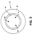
- FIG. 3 illustrates a plan view of the welds 66-70 about the batter cap 42 where the welds are sequentially applied as 120° phasing differential.
- One weldment area such as weld 66, is the subject of a peak current node while the other welds 68 and 70 are lagging weld 66 with respect to the peak current.
- weld 68 is the subject of a peak current node while the other weldment areas 66 and 70 lag with respect to peak current.
- the current phase shift then makes the weld 70 the subject of a peak current node while the other two lag. This process is repeated until the desired weldment is achieved.
- FIG. 4 illustrates the cycles of the power during the welding operation.
- FIG. 4 is indicative of one multiple waveform of a complete weld cycle for the three welds 66, 68 and 70.
- Current peak 66a corresponds to weld 66
- 68a corresponds to weld 68
- 70a corresponds to weld 70.
Landscapes
- Engineering & Computer Science (AREA)
- Mechanical Engineering (AREA)
- Chemical & Material Sciences (AREA)
- Chemical Kinetics & Catalysis (AREA)
- Electrochemistry (AREA)
- General Chemical & Material Sciences (AREA)
- Connection Of Batteries Or Terminals (AREA)
- Battery Mounting, Suspending (AREA)
- Resistance Welding (AREA)
Abstract
Description
Claims (7)
- A resistance welding process for welding together metal objects (40,42) which includes connecting the phases of a three-phase source of power (20,22,24) to respective pairs of resistance welding electrodes (34,36,38), engaging the electrodes with one of the objects(40) and while contacting the object (40) with the other object(42) and sequentially feeding the power to the respective pairs of electrodes (34,36,38), characterized in that one of the objects is a connector strip (40) and the other is a battery cap (42) and in that the battery cap (42) is relatively massive as compared to the connector strip (40).
- The process of claim 1 wherein said sequential application of power is time controlled.
- The process of claim 1 wherein said sequential application of power is phase controlled.
- The process of claim 1 wherein said plurality of electrodes is three electrodes.
- The process of claim 1 wherein the sequential application of power is peak power.
- The process of claim 5 wherein the three-phase source is approximately 400 Hz.
- The process of claim 6 including the step of reducing the three-phase power to 3 V at the welding electrodes.
Applications Claiming Priority (3)
| Application Number | Priority Date | Filing Date | Title |
|---|---|---|---|
| US925174 | 1986-10-31 | ||
| US07/925,174 US5298712A (en) | 1992-08-06 | 1992-08-06 | Welding system for a battery pack |
| PCT/US1993/007477 WO1994003300A1 (en) | 1992-08-06 | 1993-08-03 | Welding system for a battery pack |
Publications (3)
| Publication Number | Publication Date |
|---|---|
| EP0608408A1 EP0608408A1 (en) | 1994-08-03 |
| EP0608408A4 EP0608408A4 (en) | 1994-12-28 |
| EP0608408B1 true EP0608408B1 (en) | 1998-12-23 |
Family
ID=25451329
Family Applications (1)
| Application Number | Title | Priority Date | Filing Date |
|---|---|---|---|
| EP93918699A Expired - Lifetime EP0608408B1 (en) | 1992-08-06 | 1993-08-03 | Welding process for a battery pack |
Country Status (5)
| Country | Link |
|---|---|
| US (1) | US5298712A (en) |
| EP (1) | EP0608408B1 (en) |
| JP (1) | JPH07502456A (en) |
| DE (1) | DE69322758T2 (en) |
| WO (1) | WO1994003300A1 (en) |
Families Citing this family (6)
| Publication number | Priority date | Publication date | Assignee | Title |
|---|---|---|---|---|
| US5593604A (en) * | 1995-05-04 | 1997-01-14 | Motorola, Inc. | Method of resistance welding thin elements |
| DE29601662U1 (en) * | 1996-02-01 | 1996-04-18 | AKKU fit GmbH, 72762 Reutlingen | Spot welder |
| US6645669B2 (en) * | 2001-07-06 | 2003-11-11 | Black & Decker Inc. | Battery pack and method for constructing same |
| FR2905935A1 (en) * | 2006-09-18 | 2008-03-21 | Cogema | PLASTIC BAG WELDING DEVICE AND METHOD FOR HEATING ITS HEATING RIBBONS |
| US20090250440A1 (en) * | 2008-04-04 | 2009-10-08 | Yap Tze-Yee Ryan | Out-of-phase electrical welder and process |
| CN218891307U (en) | 2020-01-13 | 2023-04-21 | 米沃奇电动工具公司 | Portable welding machine powered by battery pack |
Family Cites Families (8)
| Publication number | Priority date | Publication date | Assignee | Title |
|---|---|---|---|---|
| US1189584A (en) * | 1915-04-05 | 1916-07-04 | Charles H Kicklighter | Apparatus for and method of electric fastening of metals. |
| US2243832A (en) * | 1938-06-16 | 1941-06-03 | Aluminum Co Of America | Welding apparatus and method |
| FR1251172A (en) * | 1960-03-15 | 1961-01-13 | Standard Pressed Steel Co | Resistance Welding Improvements |
| DE1265837B (en) * | 1966-05-28 | 1968-04-11 | Siemens Ag | Electric welding machine with a device for protecting the operating personnel |
| FR2125768A5 (en) * | 1971-02-19 | 1972-09-29 | Accumulateurs Fixes | |
| DE2158883A1 (en) * | 1971-11-27 | 1973-05-30 | Schorch Gmbh | ADJUSTABLE WELDING CURRENT SOURCE |
| JPS606073B2 (en) * | 1979-11-07 | 1985-02-15 | 松下電器産業株式会社 | Method for manufacturing a battery with a spiral electrode body |
| US4322597A (en) * | 1980-06-30 | 1982-03-30 | General Electric Company | Method and apparatus for interconnecting electrochemical cells for a battery |
-
1992
- 1992-08-06 US US07/925,174 patent/US5298712A/en not_active Expired - Fee Related
-
1993
- 1993-08-03 DE DE69322758T patent/DE69322758T2/en not_active Expired - Fee Related
- 1993-08-03 EP EP93918699A patent/EP0608408B1/en not_active Expired - Lifetime
- 1993-08-03 WO PCT/US1993/007477 patent/WO1994003300A1/en not_active Ceased
- 1993-08-03 JP JP6505610A patent/JPH07502456A/en active Pending
Also Published As
| Publication number | Publication date |
|---|---|
| DE69322758D1 (en) | 1999-02-04 |
| JPH07502456A (en) | 1995-03-16 |
| WO1994003300A1 (en) | 1994-02-17 |
| DE69322758T2 (en) | 1999-06-10 |
| EP0608408A4 (en) | 1994-12-28 |
| EP0608408A1 (en) | 1994-08-03 |
| US5298712A (en) | 1994-03-29 |
Similar Documents
| Publication | Publication Date | Title |
|---|---|---|
| ATE363358T1 (en) | ARC WELDING APPARATUS AND METHOD USING A STACK UNIT OF FUEL CELLS | |
| KR100727377B1 (en) | Metal member joining method and reflow soldering method | |
| EP0608408B1 (en) | Welding process for a battery pack | |
| US5140126A (en) | Resistance welding method and resistance welding device for lead acid battery | |
| EP0261328B1 (en) | Seam welder | |
| US2829238A (en) | Electric arc projection welding | |
| GB2297934A (en) | Stud welding apparatus | |
| JPH0367476B2 (en) | ||
| JPS60240389A (en) | Spot welding method | |
| JPS5820373A (en) | Method and device for narrow groove welding | |
| EP0185014B1 (en) | Resistance welder | |
| JP2567155Y2 (en) | Spot welding machine | |
| US5120924A (en) | Welding method for coated metal articles | |
| JPH0368788B2 (en) | ||
| WO1986000035A1 (en) | Resistance welder | |
| JPH01321078A (en) | Pulse arc welding power source | |
| JPS589773A (en) | Capacitor discharge type stud welding machine | |
| DE3665534D1 (en) | Spot welding device for dentistry | |
| JP3856355B2 (en) | Consumable electrode type AC gas shielded arc welding method and apparatus | |
| JPH0677846B2 (en) | Resistance welder | |
| SU1692782A1 (en) | Multiple-post power supply system | |
| JPS62248573A (en) | Capacitor discharging type stud welding method and its device | |
| KR880000913B1 (en) | Bipolar Shorting Arc Welding Machine | |
| JPS6255952B2 (en) | ||
| JPS63177977A (en) | Spot welding method |
Legal Events
| Date | Code | Title | Description |
|---|---|---|---|
| PUAI | Public reference made under article 153(3) epc to a published international application that has entered the european phase |
Free format text: ORIGINAL CODE: 0009012 |
|
| AK | Designated contracting states |
Kind code of ref document: A1 Designated state(s): DE FR GB NL |
|
| 17P | Request for examination filed |
Effective date: 19940425 |
|
| A4 | Supplementary search report drawn up and despatched |
Effective date: 19941104 |
|
| AK | Designated contracting states |
Kind code of ref document: A4 Designated state(s): DE FR GB NL |
|
| 17Q | First examination report despatched |
Effective date: 19960404 |
|
| GRAG | Despatch of communication of intention to grant |
Free format text: ORIGINAL CODE: EPIDOS AGRA |
|
| GRAG | Despatch of communication of intention to grant |
Free format text: ORIGINAL CODE: EPIDOS AGRA |
|
| GRAH | Despatch of communication of intention to grant a patent |
Free format text: ORIGINAL CODE: EPIDOS IGRA |
|
| GRAH | Despatch of communication of intention to grant a patent |
Free format text: ORIGINAL CODE: EPIDOS IGRA |
|
| GRAA | (expected) grant |
Free format text: ORIGINAL CODE: 0009210 |
|
| AK | Designated contracting states |
Kind code of ref document: B1 Designated state(s): DE FR GB NL |
|
| REF | Corresponds to: |
Ref document number: 69322758 Country of ref document: DE Date of ref document: 19990204 |
|
| ET | Fr: translation filed | ||
| PLBE | No opposition filed within time limit |
Free format text: ORIGINAL CODE: 0009261 |
|
| STAA | Information on the status of an ep patent application or granted ep patent |
Free format text: STATUS: NO OPPOSITION FILED WITHIN TIME LIMIT |
|
| 26N | No opposition filed | ||
| PGFP | Annual fee paid to national office [announced via postgrant information from national office to epo] |
Ref country code: GB Payment date: 20000201 Year of fee payment: 7 |
|
| PGFP | Annual fee paid to national office [announced via postgrant information from national office to epo] |
Ref country code: NL Payment date: 20000204 Year of fee payment: 7 |
|
| PGFP | Annual fee paid to national office [announced via postgrant information from national office to epo] |
Ref country code: FR Payment date: 20000228 Year of fee payment: 7 Ref country code: DE Payment date: 20000228 Year of fee payment: 7 |
|
| PG25 | Lapsed in a contracting state [announced via postgrant information from national office to epo] |
Ref country code: GB Free format text: LAPSE BECAUSE OF NON-PAYMENT OF DUE FEES Effective date: 20000803 |
|
| PG25 | Lapsed in a contracting state [announced via postgrant information from national office to epo] |
Ref country code: NL Free format text: LAPSE BECAUSE OF NON-PAYMENT OF DUE FEES Effective date: 20010301 |
|
| GBPC | Gb: european patent ceased through non-payment of renewal fee |
Effective date: 20000803 |
|
| PG25 | Lapsed in a contracting state [announced via postgrant information from national office to epo] |
Ref country code: FR Free format text: LAPSE BECAUSE OF NON-PAYMENT OF DUE FEES Effective date: 20010430 |
|
| NLV4 | Nl: lapsed or anulled due to non-payment of the annual fee |
Effective date: 20010301 |
|
| PG25 | Lapsed in a contracting state [announced via postgrant information from national office to epo] |
Ref country code: DE Free format text: LAPSE BECAUSE OF NON-PAYMENT OF DUE FEES Effective date: 20010501 |
|
| REG | Reference to a national code |
Ref country code: FR Ref legal event code: ST |