EP0607980A1 - A vibration wave driven motor and a printing apparatus - Google Patents
A vibration wave driven motor and a printing apparatus Download PDFInfo
- Publication number
- EP0607980A1 EP0607980A1 EP94100823A EP94100823A EP0607980A1 EP 0607980 A1 EP0607980 A1 EP 0607980A1 EP 94100823 A EP94100823 A EP 94100823A EP 94100823 A EP94100823 A EP 94100823A EP 0607980 A1 EP0607980 A1 EP 0607980A1
- Authority
- EP
- European Patent Office
- Prior art keywords
- contact
- elastic member
- flange
- vibration
- stator
- Prior art date
- Legal status (The legal status is an assumption and is not a legal conclusion. Google has not performed a legal analysis and makes no representation as to the accuracy of the status listed.)
- Granted
Links
- 230000002093 peripheral effect Effects 0.000 claims abstract description 22
- 230000002829 reductive effect Effects 0.000 description 2
- 229910000838 Al alloy Inorganic materials 0.000 description 1
- 230000002411 adverse Effects 0.000 description 1
- 230000003247 decreasing effect Effects 0.000 description 1
- 238000001514 detection method Methods 0.000 description 1
- 230000002401 inhibitory effect Effects 0.000 description 1
- 239000011810 insulating material Substances 0.000 description 1
- 239000000463 material Substances 0.000 description 1
- 239000007769 metal material Substances 0.000 description 1
- 230000002441 reversible effect Effects 0.000 description 1
Images


Classifications
-
- H—ELECTRICITY
- H02—GENERATION; CONVERSION OR DISTRIBUTION OF ELECTRIC POWER
- H02N—ELECTRIC MACHINES NOT OTHERWISE PROVIDED FOR
- H02N2/00—Electric machines in general using piezoelectric effect, electrostriction or magnetostriction
- H02N2/02—Electric machines in general using piezoelectric effect, electrostriction or magnetostriction producing linear motion, e.g. actuators; Linear positioners ; Linear motors
- H02N2/08—Electric machines in general using piezoelectric effect, electrostriction or magnetostriction producing linear motion, e.g. actuators; Linear positioners ; Linear motors using travelling waves, i.e. Rayleigh surface waves
Definitions
- the present invention relates to a vibration wave driven motor and, more particularly, to a vibration wave driven motor of a type in which an elastic member along which a travelling wave is generated is kept into tight contact with a rail-like stator, and the elastic member is moved along the rail-like stator, and a printing apparatus using this vibration wave driven motor.
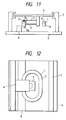
- FIG. 11 A conventional vibration wave driven motor of this type is shown in Figs. 11 and 12.
- An elastic member 1 consists of a metal material and has a projection 1a on a sliding surface side.
- An AC voltage is applied to piezoelectric elements 2 bonded to the upper surface of the elastic member 1 to generate a travelling vibration wave.
- the principle of generating the travelling vibration wave and the structure of the piezoelectric elements 2 are known, and a detailed description thereof will be omitted.
- AC voltages having a 90° phase difference along the time axis are applied to two drive piezoelectric element groups spaced apart from each other at an angular interval of 90°, thereby generating a travelling vibration wave.
- a rail-like stator 8 is in frictional contact with the elastic member 1 and fixed on a bottom plate 9 of a motor case. The rail-like stator 8 is kept in contact with the elastic member 1 through a vibration insulating material 5 (e.g., a felt) by a pressure spring 3.
- a vibration insulating material 5 e.g., a felt
- a plate-like auxiliary support 6 is bonded to a projection 1b formed at one linear portion of the elastic member 1 and supports a table 4, so that the elastic member 1 can linearly move smoothly together with the table 4 without cluttering.
- the contact width between the elastic member 1 and the rail-like stator 8 is set large to reduce the rigidness of the plate-like auxiliary support 6. Hence, the elastic member 1 conforms to the frictional surface of the rail-like stator, thereby stably moving the elastic member 1.
- the rail-like stator 8 has a flange 8a to softly receive the vibration of the elastic member 1. That is, the rail-like stator 8 has spring properties.
- This motor is used for driving a printing head in a printer of, e.g., a bubble jet scheme.
- the printing head is mounted on a carriage (not shown) mounted on the table 4 to linearly reciprocate the printing head.
- the amplitude of the vibration of the elastic member 1 in a Z direction is large in its outer peripheral portion in the conventional example and small in its inner peripheral portion, as shown in Fig. 13.
- the vibrations at the flange 8a of the rail-like stator 8 have amplitudes opposite to those of the elastic member 1.
- the flange 8a is set in a state 800a. Only the outer peripheral portion (edge) of the elastic member is in contact with the flange. In this state, the contact width is small, and a stable contact state cannot be obtained.
- the distal end of the flange is brought into contact with or separated from the inner periphery of the elastic member 1 to generate noise.
- the contact portion is the proximal portion of the flange, and the spring properties of the flange cannot be sufficiently exhibited. As a result, the vibrations of the elastic member cannot be received softly and noise is generated.
- An aspect of the present invention is to set a constant ratio of the amplitude of a rail-like stator to the amplitude of an elastic member throughout the entire contact area, thereby reducing noise of the elastic member and achieving high-speed movement of the elastic member.
- Fig. 1 is a schematic view showing the main part of a bubble jet printer according to the first embodiment of the present invention.
- a rail-like stator 80 is located in a state reverse to that in Fig. 11.
- the distal end of a flange 80a is located on the outer peripheral side of one linear portion of an elastic member 1.
- the inner peripheral side of the linear portion of the elastic member 1 is located on the proximal side of the flange 80a.
- Fig. 2 shows a vibrated state between the elastic member 1 and the flange 80a of the rail-like stator 80.
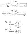
- Figs. 3A and 3B show contact portions, i.e., B and C portions of the elastic member 1 and the rail-like stator 80 viewed from an A direction, respectively.
- the flange 80a has response amplitudes R B and R C in a Z direction (Fig. 2).
- the elastic member 1 has amplitudes S B and S C in the Z direction (Fig. 2). These amplitudes satisfy condition R B /S B ⁇ R C /S C .
- the ratio R/S of the response amplitude R of the flange of the rail-like stator 80 to the amplitude S of the elastic member 1 is kept almost constant in almost all the contact portions between the elastic member 1 and the stator 80 in addition to the above-mentioned contact portions, i.e., the B and C portions, as a matter of course.
- Figs. 4A and 4B show the elliptical loci of the mass points of the B and C portions of the elastic member 1.
- T B T C
- S B ⁇ S C the sliding loss is reduced for R B /S B ⁇ R C /S C . Therefore, increasing the contact width does not reduce the velocity.
- noise may be generated unless the ratio R/S is a predetermined value or more, the velocity is reduced with a larger ratio R/S. If R B /S B ⁇ R C /S C , then a condition for inhibiting noise must be satisfied for a minimum ratio R/S. Therefore, the velocity becomes lower than that for R B /S B ⁇ R C /S C .
- the elastic member 1 When the R/S is kept almost constant in the entire area of the contact portions, the elastic member 1 can be moved at high speed without any noise. In addition, since the contact state is stable, stable driving can be performed. More specifically, if the contact width, the amplitude S B of the elastic member 1 in the Z direction, the amplitude S C , and the material of the flange 80a are 4 mm, 2 ⁇ mP-P (peak-to-peak), about 0.5 to 1 ⁇ mP-P, and an aluminum alloy, respectively, the flange 80a has a length (l) of 4.5 to 6 mm and a thickness (t) of about 1.5 to 3 mm.
- FIGs. 5 and 6 show the second embodiment of the present invention.
- An elastic member 1 is fixed to a table 40 through a plate-like auxiliary support 6.
- a rail-like stator 81 is fixed to one side of a bottom plate 90.
- Two bearing shafts 11 are fixed on the table 40 along a B Y direction, and rollers 10a are mounted at the distal ends of the bearing shafts 11, respectively.
- a recessed groove 81b in which the rollers 10a are fitted is formed in the upper surface of the rail-like stator 81.
- the recessed groove 81b inhibits movement of the elastic member 1 in a B X direction.
- a flange 81a having spring properties is formed on the lower surface opposing the upper surface of the rail-like stator 81.
- the lower surface of the flange 81a serves as a sliding surface which is brought into contact with a drive surface of the elastic member 1.
- the flange 81a has the same properties as in the first embodiment. That is, the ratio of the response amplitude of the flange to the amplitude of the elastic member in the entire contact area is kept almost constant.
- a guide portion 90a constituted by a flat surface along the B Y direction is formed on the other side of the bottom plate 90.
- a roller 10b mounted in the bearing shafts 11 fixed to the table 40 is in contact with the guide portion 90a.
- a regulation portion 90b parallel to the guide portion 90a is formed at the upper portion of the guide portion 90a so as to be spaced apart from the roller 10b by a small gap. The regulation portion 90b limits vertical movement of the roller 10b.
- the bearing resistance can be lower than that of the first embodiment, and the motor output can be increased.
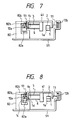
- Fig. 7 shows the third embodiment of the present invention.
- a second flange 82c is formed in a rail-like stator 82 to oppose a flange 82a contacting an elastic member 1.
- a recessed groove 82b is formed in the lower surface of the second flange 82c, and a roller 12a is fitted in the recessed groove 82b, thereby obtaining a low-profile structure as compared with that in Fig. 5.
- Fig. 8 shows the fourth embodiment of the present invention. Only an outer peripheral portion 1c and an inner peripheral portion 1d of one linear portion of an elastic member 1 are in contact with a flange 82a of a rail-like stator 82 due to the following reason. It is much easier to set a constant ratio of the response amplitude of the flange to the amplitude of the elastic member in only the outer and inner peripheral portions than in all the areas from the outer peripheral side to the inner peripheral side, as shown in Fig. 7.
- Fig. 9 shows the fifth embodiment of the present invention.
- the outer peripheral portion of one linear portion of an elastic member 1 is in contact with a first flange 83a, and the inner peripheral portion of the elastic member 1 is in contact with a second flange 83b.
- the contact width is kept small, the ratio of the response amplitude of the flange to the amplitude of the elastic member cannot be kept constant in all the contact areas.
- Fig. 10 is a perspective view of a bubble jet printing apparatus using the above vibration wave driven motor.
- a printing head 29 is mounted on a carriage 42 to inject an ink to print information on a paper sheet fed by a paper feed vibration wave driven motor 1' (disclosed in Japanese Laid-Open Patent Application No. 3-31137).
- An encoder slit plate 24 is formed to control the feed velocity of the carriage.
- a paper feed amount detection rotary encoder 21 is rotated by a roller 22 brought into tight contact with the upper surface of a paper sheet 20.
- the elastic member is moved along the rail-like stator.
- a rotary type a type in which an elastic member is stationary and a stator is movable, or any other type is applicable herein.
- the ratio of the response amplitude of a rail-like stator to the amplitude of an elastic member is kept almost constant in all the contact areas (i.e., from the outer peripheral portion to the inner peripheral portion of the elastic member). Therefore, the elastic member can be moved stably at high speed without any noise.
- the above vibration wave driven motor is utilized as a drive source for driving a printing head or the like to perform high-speed, high-precision printing without any noise.
- the distal end of a flange of a stator serving as a contact member is located on the outer peripheral side of one linear portion of an elastic member serving as a vibration member, and the inner peripheral side of this linear portion of the elastic member is located on the proximal side of the flange.
- the ratio of the response amplitude of the flange of the stator to the amplitude of the elastic member is kept almost constant in all areas of contact portions between the two members.
Abstract
Description
- The present invention relates to a vibration wave driven motor and, more particularly, to a vibration wave driven motor of a type in which an elastic member along which a travelling wave is generated is kept into tight contact with a rail-like stator, and the elastic member is moved along the rail-like stator, and a printing apparatus using this vibration wave driven motor.
- A conventional vibration wave driven motor of this type is shown in Figs. 11 and 12.
- An
elastic member 1 consists of a metal material and has aprojection 1a on a sliding surface side. An AC voltage is applied topiezoelectric elements 2 bonded to the upper surface of theelastic member 1 to generate a travelling vibration wave. The principle of generating the travelling vibration wave and the structure of thepiezoelectric elements 2 are known, and a detailed description thereof will be omitted. AC voltages having a 90° phase difference along the time axis are applied to two drive piezoelectric element groups spaced apart from each other at an angular interval of 90°, thereby generating a travelling vibration wave. A rail-like stator 8 is in frictional contact with theelastic member 1 and fixed on abottom plate 9 of a motor case. The rail-like stator 8 is kept in contact with theelastic member 1 through a vibration insulating material 5 (e.g., a felt) by apressure spring 3. - A plate-like
auxiliary support 6 is bonded to aprojection 1b formed at one linear portion of theelastic member 1 and supports a table 4, so that theelastic member 1 can linearly move smoothly together with the table 4 without cluttering. The contact width between theelastic member 1 and the rail-like stator 8 is set large to reduce the rigidness of the plate-likeauxiliary support 6. Hence, theelastic member 1 conforms to the frictional surface of the rail-like stator, thereby stably moving theelastic member 1. - The rail-
like stator 8 has aflange 8a to softly receive the vibration of theelastic member 1. That is, the rail-like stator 8 has spring properties. - This motor is used for driving a printing head in a printer of, e.g., a bubble jet scheme. The printing head is mounted on a carriage (not shown) mounted on the table 4 to linearly reciprocate the printing head.
- The amplitude of the vibration of the
elastic member 1 in a Z direction is large in its outer peripheral portion in the conventional example and small in its inner peripheral portion, as shown in Fig. 13. To the contrary, the vibrations at theflange 8a of the rail-like stator 8 have amplitudes opposite to those of theelastic member 1. As shown in Fig. 13, when the elastic member is set in astate 100, theflange 8a is set in astate 800a. Only the outer peripheral portion (edge) of the elastic member is in contact with the flange. In this state, the contact width is small, and a stable contact state cannot be obtained. In some cases, the distal end of the flange is brought into contact with or separated from the inner periphery of theelastic member 1 to generate noise. In addition, the contact portion is the proximal portion of the flange, and the spring properties of the flange cannot be sufficiently exhibited. As a result, the vibrations of the elastic member cannot be received softly and noise is generated. - Even if the elastic member is in contact with the
flange 8a from the outer to inner peripheries, the contact state between the elastic member and theflange 8a is not always uniform, and the sliding loss is large, thereby decreasing the feed velocity of the table 4. - If the above adverse influences are to be eliminated by reducing the contact width between the
elastic member 1 and theflange 8a of the rail-like stator 8, as shown in Fig. 14, the position of theelastic member 1 in a BZ direction becomes unstable because of dimensional errors of each parts. As a result, stable feeding cannot be performed. - It is an object of the present invention to provide a vibration wave driven motor which hardly generates noise and achieves high-speed stable movement of an elastic member.
- It is another object of the present invention to provide a printing apparatus for realizing high-speed, high-precision printing with a low noise level.
- An aspect of the present invention is to set a constant ratio of the amplitude of a rail-like stator to the amplitude of an elastic member throughout the entire contact area, thereby reducing noise of the elastic member and achieving high-speed movement of the elastic member.
-
- Fig. 1 is a side view showing the first embodiment of the present invention;
- Fig. 2 is a view showing the main part in Fig. 1;
- Figs. 3A and 3B are views showing contact states between an
elastic member 1 and a rail-like stator 80; - Figs. 4A and 4B are views showing elliptical loci of the
elastic member 1; - Fig. 5 is a side view showing the second embodiment of the present invention;
- Fig. 6 is a plan view showing the second embodiment of the present invention;
- Fig. 7 is a side view showing the third embodiment of the present invention;
- Fig. 8 is a side view showing the fourth embodiment of the present invention;
- Fig. 9 is a side view showing the fifth embodiment of the present invention;
- Fig. 10 is a perspective view showing an arrangement of a printing apparatus using a vibration wave driven motor according to the present invention;
- Fig. 11 is a side view showing a conventional vibration wave driven motor;
- Fig. 12 is a plan view showing the conventional vibration wave driven motor;
- Fig. 13 is a view showing the main part in Fig. 11; and
- Fig. 14 is a side view showing another conventional vibration wave motor.
- The present invention will be described in detail with reference to illustrated embodiments. The same reference numerals as in the prior arts denote the same parts in the following embodiments, and a detailed description thereof will be omitted.
- Fig. 1 is a schematic view showing the main part of a bubble jet printer according to the first embodiment of the present invention. In this embodiment, a rail-
like stator 80 is located in a state reverse to that in Fig. 11. The distal end of aflange 80a is located on the outer peripheral side of one linear portion of anelastic member 1. The inner peripheral side of the linear portion of theelastic member 1 is located on the proximal side of theflange 80a. Fig. 2 shows a vibrated state between theelastic member 1 and theflange 80a of the rail-like stator 80. Figs. 3A and 3B show contact portions, i.e., B and C portions of theelastic member 1 and the rail-like stator 80 viewed from an A direction, respectively. Referring to Figs. 3A and 3B, theflange 80a has response amplitudes RB and RC in a Z direction (Fig. 2). Theelastic member 1 has amplitudes SB and SC in the Z direction (Fig. 2). These amplitudes satisfy condition
like stator 80 to the amplitude S of theelastic member 1 is kept almost constant in almost all the contact portions between theelastic member 1 and thestator 80 in addition to the above-mentioned contact portions, i.e., the B and C portions, as a matter of course. - Figs. 4A and 4B show the elliptical loci of the mass points of the B and C portions of the
elastic member 1. As can be apparent from Figs. 4A and 4B, since the amplitudes in the feed direction are equal to each other (


- When the R/S is kept almost constant in the entire area of the contact portions, the
elastic member 1 can be moved at high speed without any noise. In addition, since the contact state is stable, stable driving can be performed. More specifically, if the contact width, the amplitude SB of theelastic member 1 in the Z direction, the amplitude SC, and the material of theflange 80a are 4 mm, 2µmP-P (peak-to-peak), about 0.5 to 1µmP-P, and an aluminum alloy, respectively, theflange 80a has a length (ℓ) of 4.5 to 6 mm and a thickness (t) of about 1.5 to 3 mm. - Figs. 5 and 6 show the second embodiment of the present invention. An
elastic member 1 is fixed to a table 40 through a plate-likeauxiliary support 6. A rail-like stator 81 is fixed to one side of abottom plate 90. Two bearingshafts 11 are fixed on the table 40 along a BY direction, androllers 10a are mounted at the distal ends of the bearingshafts 11, respectively. A recessedgroove 81b in which therollers 10a are fitted is formed in the upper surface of the rail-like stator 81. The recessedgroove 81b inhibits movement of theelastic member 1 in a BX direction. Aflange 81a having spring properties is formed on the lower surface opposing the upper surface of the rail-like stator 81. The lower surface of theflange 81a serves as a sliding surface which is brought into contact with a drive surface of theelastic member 1. Theflange 81a has the same properties as in the first embodiment. That is, the ratio of the response amplitude of the flange to the amplitude of the elastic member in the entire contact area is kept almost constant. - A
guide portion 90a constituted by a flat surface along the BY direction is formed on the other side of thebottom plate 90. Aroller 10b mounted in the bearingshafts 11 fixed to the table 40 is in contact with theguide portion 90a. Aregulation portion 90b parallel to theguide portion 90a is formed at the upper portion of theguide portion 90a so as to be spaced apart from theroller 10b by a small gap. Theregulation portion 90b limits vertical movement of theroller 10b. - As described above, if all the bearings are constituted by rollers, the bearing resistance can be lower than that of the first embodiment, and the motor output can be increased.
- Fig. 7 shows the third embodiment of the present invention. A
second flange 82c is formed in a rail-like stator 82 to oppose aflange 82a contacting anelastic member 1. A recessedgroove 82b is formed in the lower surface of thesecond flange 82c, and aroller 12a is fitted in the recessedgroove 82b, thereby obtaining a low-profile structure as compared with that in Fig. 5. - Fig. 8 shows the fourth embodiment of the present invention. Only an outer
peripheral portion 1c and an inner peripheral portion 1d of one linear portion of anelastic member 1 are in contact with aflange 82a of a rail-like stator 82 due to the following reason. It is much easier to set a constant ratio of the response amplitude of the flange to the amplitude of the elastic member in only the outer and inner peripheral portions than in all the areas from the outer peripheral side to the inner peripheral side, as shown in Fig. 7. - Fig. 9 shows the fifth embodiment of the present invention. The outer peripheral portion of one linear portion of an
elastic member 1 is in contact with afirst flange 83a, and the inner peripheral portion of theelastic member 1 is in contact with asecond flange 83b. In this case, unless the contact width is kept small, the ratio of the response amplitude of the flange to the amplitude of the elastic member cannot be kept constant in all the contact areas. - Fig. 10 is a perspective view of a bubble jet printing apparatus using the above vibration wave driven motor. A
printing head 29 is mounted on acarriage 42 to inject an ink to print information on a paper sheet fed by a paper feed vibration wave driven motor 1' (disclosed in Japanese Laid-Open Patent Application No. 3-31137). Anencoder slit plate 24 is formed to control the feed velocity of the carriage. A paper feed amountdetection rotary encoder 21 is rotated by aroller 22 brought into tight contact with the upper surface of apaper sheet 20. - In the above description, the elastic member is moved along the rail-like stator. However, a rotary type, a type in which an elastic member is stationary and a stator is movable, or any other type is applicable herein.
- As has been described above, according to the present invention, the ratio of the response amplitude of a rail-like stator to the amplitude of an elastic member is kept almost constant in all the contact areas (i.e., from the outer peripheral portion to the inner peripheral portion of the elastic member). Therefore, the elastic member can be moved stably at high speed without any noise.
- The above vibration wave driven motor is utilized as a drive source for driving a printing head or the like to perform high-speed, high-precision printing without any noise.
- The distal end of a flange of a stator serving as a contact member is located on the outer peripheral side of one linear portion of an elastic member serving as a vibration member, and the inner peripheral side of this linear portion of the elastic member is located on the proximal side of the flange. The ratio of the response amplitude of the flange of the stator to the amplitude of the elastic member is kept almost constant in all areas of contact portions between the two members.
Claims (5)
- A vibration driven motor including a vibration member (1, 2) for generating a vibration wave therein and a contact member (80) in frictional contact with said vibration member, said vibration member and said contact member being moved relative to each other, characterized in that
a ratio of a response width of said contact member to an amplitude of said vibration member is kept substantially constant in all areas of contact portions of said vibration and contact members. - A motor according to claim 1, characterized in that said vibration member comprises an elastic member having a pair of linear portions and a pair of arcuated portions, so that one of said linear portions of said elastic member is in contact with said contact portion of said contact member and is moved along said contact member by the vibration wave.
- A motor according to claim 2, characterized in that an outer peripheral side of one of said linear portions of said elastic member is located at a distal end portion of a flange formed on said contact member, and an inner peripheral side of said one linear portion is located on a side proximal to said distal end portion of said flange.
- A motor according to claim 2, characterized in that an outer peripheral side of one of said linear portions of said elastic member is in contact with a first flange of said contact member, and an inner peripheral side of said one linear portion is in contact with a second flange of said contact member.
- A printing apparatus using said vibration wave driven motor defined in any one of claims 1 to 4 as a drive source.
Applications Claiming Priority (2)
| Application Number | Priority Date | Filing Date | Title |
|---|---|---|---|
| JP9391/93 | 1993-01-22 | ||
| JP00939193A JP3155109B2 (en) | 1993-01-22 | 1993-01-22 | Vibration wave driving device and printer device |
Publications (2)
| Publication Number | Publication Date |
|---|---|
| EP0607980A1 true EP0607980A1 (en) | 1994-07-27 |
| EP0607980B1 EP0607980B1 (en) | 1999-05-06 |
Family
ID=11719145
Family Applications (1)
| Application Number | Title | Priority Date | Filing Date |
|---|---|---|---|
| EP94100823A Expired - Lifetime EP0607980B1 (en) | 1993-01-22 | 1994-01-20 | A vibration wave driven motor and a printing apparatus |
Country Status (4)
| Country | Link |
|---|---|
| US (1) | US5945771A (en) |
| EP (1) | EP0607980B1 (en) |
| JP (1) | JP3155109B2 (en) |
| DE (1) | DE69418219T2 (en) |
Families Citing this family (4)
| Publication number | Priority date | Publication date | Assignee | Title |
|---|---|---|---|---|
| US5596241A (en) * | 1993-01-18 | 1997-01-21 | Canon Kabushiki Kaisha | Vibration wave driven linear-motor or printer |
| JPH11289780A (en) * | 1998-03-31 | 1999-10-19 | Minolta Co Ltd | Driver using electromechanical converting element |
| US7348710B2 (en) | 2005-11-01 | 2008-03-25 | Piezomotor Uppsala Ab | Robust electromechanical motor |
| JP5843469B2 (en) * | 2011-04-26 | 2016-01-13 | キヤノン株式会社 | Vibration wave motor |
Citations (5)
| Publication number | Priority date | Publication date | Assignee | Title |
|---|---|---|---|---|
| JPS60230882A (en) * | 1984-05-02 | 1985-11-16 | Nec Corp | Carrier driver for printer |
| JPH03155375A (en) * | 1989-11-10 | 1991-07-03 | Canon Inc | Linear motor unit |
| EP0435496A1 (en) * | 1989-12-08 | 1991-07-03 | Canon Kabushiki Kaisha | A vibration driven motor and thermal jet type printer using the same |
| EP0475752A2 (en) * | 1990-09-12 | 1992-03-18 | Canon Kabushiki Kaisha | Vibration-driven motor |
| EP0530822A2 (en) * | 1991-09-05 | 1993-03-10 | Canon Kabushiki Kaisha | Guide device for vibration driven motor |
Family Cites Families (18)
| Publication number | Priority date | Publication date | Assignee | Title |
|---|---|---|---|---|
| US4831305A (en) * | 1984-04-02 | 1989-05-16 | Canon Kabushiki Kaisha | Vibration wave motor |
| JPS61154487A (en) * | 1984-12-26 | 1986-07-14 | Canon Inc | Linear oscillatory wave motor |
| US4752711A (en) * | 1985-03-29 | 1988-06-21 | Canon Kabushiki Kaisha | Vibration wave motor |
| JPS61224882A (en) * | 1985-03-29 | 1986-10-06 | Canon Inc | Vibration wave motor |
| JPS61224881A (en) * | 1985-03-29 | 1986-10-06 | Canon Inc | Vibration wave motor |
| JPS63154075A (en) * | 1986-12-17 | 1988-06-27 | Canon Inc | Oscillatory wave motor |
| US5066884A (en) * | 1989-02-10 | 1991-11-19 | Nikon Corporation | Ultrasonic motor having high drive efficiency |
| JPH02237481A (en) * | 1989-03-07 | 1990-09-20 | Canon Inc | Oscillatory wave motor |
| US5204577A (en) * | 1989-05-15 | 1993-04-20 | Nikon Corporation | Ultrasonic motor improved in driving efficiency |
| JP3030050B2 (en) * | 1989-05-30 | 2000-04-10 | オリンパス光学工業株式会社 | Ultrasonic motor |
| JPH0331137A (en) * | 1989-06-27 | 1991-02-08 | Canon Inc | Sheet feeder |
| US5140214A (en) * | 1989-09-06 | 1992-08-18 | Canon Kabushiki Kaisha | Vibration wave driven apparatus |
| US5192890A (en) * | 1989-09-25 | 1993-03-09 | Canon Kabushiki Kaisha | Vibration driven actuator |
| US5216314A (en) * | 1989-11-16 | 1993-06-01 | Canon Kabushiki Kaisha | Pressure force adjusting mechanism for a vibration wave driven motor |
| JP2993702B2 (en) * | 1990-04-02 | 1999-12-27 | キヤノン株式会社 | Vibration wave drive |
| DE69211880T2 (en) * | 1991-04-02 | 1996-11-07 | Matsushita Electric Ind Co Ltd | Ultrasonic motor with a vibrating body and thereby moving body |
| JP2962861B2 (en) * | 1991-05-20 | 1999-10-12 | キヤノン株式会社 | Vibration wave motor |
| JPH066986A (en) * | 1992-06-17 | 1994-01-14 | Canon Inc | Oscillation wave motor and manufacture thereof |
-
1993
- 1993-01-22 JP JP00939193A patent/JP3155109B2/en not_active Expired - Fee Related
-
1994
- 1994-01-20 EP EP94100823A patent/EP0607980B1/en not_active Expired - Lifetime
- 1994-01-20 DE DE69418219T patent/DE69418219T2/en not_active Expired - Lifetime
-
1997
- 1997-09-10 US US08/926,464 patent/US5945771A/en not_active Expired - Lifetime
Patent Citations (5)
| Publication number | Priority date | Publication date | Assignee | Title |
|---|---|---|---|---|
| JPS60230882A (en) * | 1984-05-02 | 1985-11-16 | Nec Corp | Carrier driver for printer |
| JPH03155375A (en) * | 1989-11-10 | 1991-07-03 | Canon Inc | Linear motor unit |
| EP0435496A1 (en) * | 1989-12-08 | 1991-07-03 | Canon Kabushiki Kaisha | A vibration driven motor and thermal jet type printer using the same |
| EP0475752A2 (en) * | 1990-09-12 | 1992-03-18 | Canon Kabushiki Kaisha | Vibration-driven motor |
| EP0530822A2 (en) * | 1991-09-05 | 1993-03-10 | Canon Kabushiki Kaisha | Guide device for vibration driven motor |
Non-Patent Citations (2)
| Title |
|---|
| PATENT ABSTRACTS OF JAPAN vol. 010, no. 092 (M - 468) 9 April 1986 (1986-04-09) * |
| PATENT ABSTRACTS OF JAPAN vol. 15, no. 387 (E - 1117) 30 September 1991 (1991-09-30) * |
Also Published As
| Publication number | Publication date |
|---|---|
| JPH06225552A (en) | 1994-08-12 |
| US5945771A (en) | 1999-08-31 |
| DE69418219T2 (en) | 2000-01-05 |
| DE69418219D1 (en) | 1999-06-10 |
| JP3155109B2 (en) | 2001-04-09 |
| EP0607980B1 (en) | 1999-05-06 |
Similar Documents
| Publication | Publication Date | Title |
|---|---|---|
| EP0598710A2 (en) | A vibration driven apparatus | |
| EP0600485B1 (en) | A supporting device for a vibration driven actuator | |
| JPS5862065A (en) | Method of correcting error of position of small drop of ink jet printer | |
| US5241234A (en) | Vibration-driven motor | |
| US5945771A (en) | Vibration wave driven motor and a printing apparatus | |
| US5596241A (en) | Vibration wave driven linear-motor or printer | |
| EP0436336B1 (en) | Vibration wave driven apparatus | |
| EP0437050B1 (en) | Vibration wave driven apparatus | |
| EP0530822B1 (en) | Guide device for vibration driven motor | |
| EP0382253B1 (en) | Sheet Feeder | |
| US5244202A (en) | Sheet feeding apparatus | |
| US5455478A (en) | Vibration wave driven apparatus | |
| EP0577376B1 (en) | Printing apparatus having vibration driven linear type actuator for carriage | |
| US4379300A (en) | Ink jet printing | |
| US4623806A (en) | Linear motor | |
| JPH06276769A (en) | Vibrating-wave linear motor and printer | |
| JPH07330187A (en) | Paper carrying device | |
| JPH06217565A (en) | Oscillatory-wave linear motor and printer | |
| JPH0739179A (en) | Oscillatory wave motor and printer using the same | |
| JPH07163164A (en) | Oscillation wave linear motor and printer | |
| WO1994018674A1 (en) | Guide device | |
| JPH05110768A (en) | Picture reader | |
| JPS63207654A (en) | Serial dot printer | |
| JPH04116037A (en) | Sheet feeding device | |
| JPS60258771A (en) | Magnetic head driver |
Legal Events
| Date | Code | Title | Description |
|---|---|---|---|
| PUAI | Public reference made under article 153(3) epc to a published international application that has entered the european phase |
Free format text: ORIGINAL CODE: 0009012 |
|
| AK | Designated contracting states |
Kind code of ref document: A1 Designated state(s): DE FR GB |
|
| 17P | Request for examination filed |
Effective date: 19941213 |
|
| 17Q | First examination report despatched |
Effective date: 19960102 |
|
| GRAG | Despatch of communication of intention to grant |
Free format text: ORIGINAL CODE: EPIDOS AGRA |
|
| GRAG | Despatch of communication of intention to grant |
Free format text: ORIGINAL CODE: EPIDOS AGRA |
|
| GRAH | Despatch of communication of intention to grant a patent |
Free format text: ORIGINAL CODE: EPIDOS IGRA |
|
| GRAH | Despatch of communication of intention to grant a patent |
Free format text: ORIGINAL CODE: EPIDOS IGRA |
|
| GRAA | (expected) grant |
Free format text: ORIGINAL CODE: 0009210 |
|
| AK | Designated contracting states |
Kind code of ref document: B1 Designated state(s): DE FR GB |
|
| PG25 | Lapsed in a contracting state [announced via postgrant information from national office to epo] |
Ref country code: FR Free format text: LAPSE BECAUSE OF FAILURE TO SUBMIT A TRANSLATION OF THE DESCRIPTION OR TO PAY THE FEE WITHIN THE PRESCRIBED TIME-LIMIT Effective date: 19990506 |
|
| REF | Corresponds to: |
Ref document number: 69418219 Country of ref document: DE Date of ref document: 19990610 |
|
| EN | Fr: translation not filed | ||
| PLBE | No opposition filed within time limit |
Free format text: ORIGINAL CODE: 0009261 |
|
| STAA | Information on the status of an ep patent application or granted ep patent |
Free format text: STATUS: NO OPPOSITION FILED WITHIN TIME LIMIT |
|
| RIN2 | Information on inventor provided after grant (corrected) |
Free format text: KIMURA, ATSUSHI, C/O CANON KABUSHIKI KAISHA * YANAGI, EIICHI, C/O CANON KABUSHIKI KAISHA * NISHIMOTO, YOSHIFUMI, C/O CANON KABUSHIKI KAISHA * SEKI, HIROYUKI, C/O CANON KABUSHIKI KAISHA * YAMAMOTO SHINJI, C/O CANON KABUSHIKI KAISHA |
|
| 26N | No opposition filed | ||
| REG | Reference to a national code |
Ref country code: GB Ref legal event code: IF02 |
|
| PGFP | Annual fee paid to national office [announced via postgrant information from national office to epo] |
Ref country code: DE Payment date: 20130131 Year of fee payment: 20 Ref country code: GB Payment date: 20130123 Year of fee payment: 20 |
|
| REG | Reference to a national code |
Ref country code: DE Ref legal event code: R071 Ref document number: 69418219 Country of ref document: DE |
|
| REG | Reference to a national code |
Ref country code: GB Ref legal event code: PE20 Expiry date: 20140119 |
|
| PG25 | Lapsed in a contracting state [announced via postgrant information from national office to epo] |
Ref country code: GB Free format text: LAPSE BECAUSE OF EXPIRATION OF PROTECTION Effective date: 20140119 Ref country code: DE Free format text: LAPSE BECAUSE OF EXPIRATION OF PROTECTION Effective date: 20140121 |