EP0607698B1 - Double-wrap brake band assembly - Google Patents
Double-wrap brake band assembly Download PDFInfo
- Publication number
- EP0607698B1 EP0607698B1 EP93310494A EP93310494A EP0607698B1 EP 0607698 B1 EP0607698 B1 EP 0607698B1 EP 93310494 A EP93310494 A EP 93310494A EP 93310494 A EP93310494 A EP 93310494A EP 0607698 B1 EP0607698 B1 EP 0607698B1
- Authority
- EP
- European Patent Office
- Prior art keywords
- slots
- tabs
- strap
- shaped
- band
- Prior art date
- Legal status (The legal status is an assumption and is not a legal conclusion. Google has not performed a legal analysis and makes no representation as to the accuracy of the status listed.)
- Expired - Lifetime
Links
- 238000006243 chemical reaction Methods 0.000 claims description 22
- 230000002093 peripheral effect Effects 0.000 claims description 22
- 229910003460 diamond Inorganic materials 0.000 claims description 11
- 239000010432 diamond Substances 0.000 claims description 11
- 241000219793 Trifolium Species 0.000 claims description 7
- 238000001125 extrusion Methods 0.000 description 40
- 230000035882 stress Effects 0.000 description 28
- 239000000463 material Substances 0.000 description 15
- 230000013011 mating Effects 0.000 description 12
- 230000005540 biological transmission Effects 0.000 description 10
- 238000003466 welding Methods 0.000 description 8
- 208000013201 Stress fracture Diseases 0.000 description 7
- 238000000034 method Methods 0.000 description 7
- 239000011324 bead Substances 0.000 description 6
- 229910000831 Steel Inorganic materials 0.000 description 4
- 238000004519 manufacturing process Methods 0.000 description 4
- 238000011056 performance test Methods 0.000 description 4
- 230000002028 premature Effects 0.000 description 4
- 230000002250 progressing effect Effects 0.000 description 4
- 239000010959 steel Substances 0.000 description 4
- 238000005219 brazing Methods 0.000 description 3
- 238000010276 construction Methods 0.000 description 3
- 239000002184 metal Substances 0.000 description 3
- 206010017076 Fracture Diseases 0.000 description 2
- 230000000712 assembly Effects 0.000 description 2
- 238000000429 assembly Methods 0.000 description 2
- 230000008642 heat stress Effects 0.000 description 2
- 239000004593 Epoxy Substances 0.000 description 1
- 239000000853 adhesive Substances 0.000 description 1
- 230000001070 adhesive effect Effects 0.000 description 1
- 230000001419 dependent effect Effects 0.000 description 1
- 230000000694 effects Effects 0.000 description 1
- 230000008030 elimination Effects 0.000 description 1
- 238000003379 elimination reaction Methods 0.000 description 1
- 230000002708 enhancing effect Effects 0.000 description 1
- 238000010438 heat treatment Methods 0.000 description 1
- 238000010008 shearing Methods 0.000 description 1
Images







Classifications
-
- F—MECHANICAL ENGINEERING; LIGHTING; HEATING; WEAPONS; BLASTING
- F16—ENGINEERING ELEMENTS AND UNITS; GENERAL MEASURES FOR PRODUCING AND MAINTAINING EFFECTIVE FUNCTIONING OF MACHINES OR INSTALLATIONS; THERMAL INSULATION IN GENERAL
- F16D—COUPLINGS FOR TRANSMITTING ROTATION; CLUTCHES; BRAKES
- F16D49/00—Brakes with a braking member co-operating with the periphery of a drum, wheel-rim, or the like
- F16D49/02—Brakes with a braking member co-operating with the periphery of a drum, wheel-rim, or the like shaped as a helical band or coil with more than one turn, with or without intensification of the braking force by the tension of the band or contracting member
-
- F—MECHANICAL ENGINEERING; LIGHTING; HEATING; WEAPONS; BLASTING
- F16—ENGINEERING ELEMENTS AND UNITS; GENERAL MEASURES FOR PRODUCING AND MAINTAINING EFFECTIVE FUNCTIONING OF MACHINES OR INSTALLATIONS; THERMAL INSULATION IN GENERAL
- F16D—COUPLINGS FOR TRANSMITTING ROTATION; CLUTCHES; BRAKES
- F16D65/00—Parts or details
- F16D65/02—Braking members; Mounting thereof
- F16D65/04—Bands, shoes or pads; Pivots or supporting members therefor
-
- F—MECHANICAL ENGINEERING; LIGHTING; HEATING; WEAPONS; BLASTING
- F16—ENGINEERING ELEMENTS AND UNITS; GENERAL MEASURES FOR PRODUCING AND MAINTAINING EFFECTIVE FUNCTIONING OF MACHINES OR INSTALLATIONS; THERMAL INSULATION IN GENERAL
- F16D—COUPLINGS FOR TRANSMITTING ROTATION; CLUTCHES; BRAKES
- F16D65/00—Parts or details
- F16D65/02—Braking members; Mounting thereof
- F16D65/04—Bands, shoes or pads; Pivots or supporting members therefor
- F16D65/06—Bands, shoes or pads; Pivots or supporting members therefor for externally-engaging brakes
- F16D65/065—Brake bands
- F16D65/067—Brake bands with means for mounting, e.g. end connection members
-
- F—MECHANICAL ENGINEERING; LIGHTING; HEATING; WEAPONS; BLASTING
- F16—ENGINEERING ELEMENTS AND UNITS; GENERAL MEASURES FOR PRODUCING AND MAINTAINING EFFECTIVE FUNCTIONING OF MACHINES OR INSTALLATIONS; THERMAL INSULATION IN GENERAL
- F16D—COUPLINGS FOR TRANSMITTING ROTATION; CLUTCHES; BRAKES
- F16D69/00—Friction linings; Attachment thereof; Selection of coacting friction substances or surfaces
- F16D2069/004—Profiled friction surfaces, e.g. grooves, dimples
Definitions
- the present invention relates to double-wrap brake bands.
- Double-wrap brake band assemblies are used in the automatic transmission of an automotive vehicle.
- Most conventional automatic transmissions are of the torque converter type wherein a driven shaft extends from the torque converter into the transmission to a clutch unit having one or more clutch drums.
- Double-wrap brake bands are positioned around the clutch drums and, with suitable hydraulic controls, effect gear changes to control the direction and speed of rotation of the output shaft or driveshaft extending from the transmission.
- Double-wrap brake bands have been widely utilized in such transmissions since they commonly provide more than twice the holding power of an otherwise similar single-wrap band.
- Brake band assemblies must be designed to optimize performance over a variety of use specifications. For instance, the band must be able to provide a desired performance level when placed in operation in a gross overload mode commonly designated as Brute Force Holding Power.
- a typical performance specification in this mode of operation requires that the transmission band withstand the application of at least 100 cycles of shifting from a forward gear to a reverse gear at open throttle of 75% to 80% of maximum engine output on dry pavement.
- Another desired performance test known as High Cycle Fatigue Loading, requires that the transmission band withstand the application of at least 70,000 cycles in one direction or gear at open throttle of at least 60% of maximum engine output.
- Conventional double-wrap brake bands designed to meet these performance specifications are usually manufactured from a relatively thick metal strap which is formed into three generally parallel bands having an annular shape. Friction linings are applied to the inner diameter surface of the annular strap member. Bracket members for engaging the anchor pin and apply pin of the transmission are secured to the ends of the strap member.
- a unitary bracket member comprising both the apply bracket and the reaction bracket is welded to the strap assembly. A s a final step on construction, the apply and reaction brackets are separated usually through the elimination of a tie member, to allow the apply bracket and reaction bracket to individually react to force applications received from the apply pin and anchor pin, respectively.
- Another double-wrap band structure such as that shown in US-A-5 012 905 discloses a similar band structure having three parallel bands formed into an approximate annular shape with friction facings fastened to the inner peripheral surfaces of the bands.
- the bracket members are secured to the band member by rivets.
- Use of such rivets successfully reduces the distortion to the band caused by the heat stresses imposed by a brazing or welding operation and further acts to reduce the stresses to the band material caused by the welding heat.
- problems have been encountered in using rivets to secure bracket members to band members due to the inability of rivet designs to withstand the operational stresses imposed by transmission use.
- the use of rivets to secure the brackets to bands imposes problems in manufacturing as a result of the multitude of loose parts required during the manufacturing process.
- EP-A-0230727 generally discloses a double-wrap brake band comprising a strap member having three curved bands of a specified thickness joined together in a generally parallel relationship by a bracket member having an annular inner peripheral surface to form a substantially annular configuration; the bracket member having a connector member joined to the ends of all three bands, an apply member secured to the end of the central band member, and a reaction member secured to the ends of the outside band members; wherein the strap member includes a plurality of slots extending therethrough.
- brake band like the band structure of the aforementioned US-A-4602706, the bracket member is secured to the strap member by welding, and hence the brake band is subject to the described problems attendant upon the welding process.
- each slot is non-circular, longitudinally oriented on the strap member and defines a perimeter edge
- the bracket member includes a plurality of extruded non-circular tabs extending from the inner peripheral surface of the bracket member for positioning within the slots to engage the slots and extend beyond an inner peripheral surface of the strap member, whereby the tabs extending beyond the inner peripheral surface of the strap member are clinched and are pressed into engagement with the perimeter edges of the slots to secure the bracket member to the strap base;
- a double-wrap brake band comprising a strap member having three curved bands of a specified thickness joined together in a generally parallel relationship by a bracket member having an annular inner peripheral surface to form a substantially annular configuration; the bracket member having a connector member joined to the ends of all three bands, an apply member secured to the end of the central band member, and a reaction member secured to the ends of the outside band members; wherein the strap member includes a plurality of oval-shaped slots extending therethrough, each slot being longitudinally oriented on the strap member and defining a perimeter edge, and the bracket member includes a plurality of extruded longitudinal tabs extending from the inner peripheral surface of the bracket member for positioning within the slots to engage the slots and extend within an inner peripheral surface of the strap member, whereby the tabs extending beyond the inner peripheral surface of the strap member are clinched and are pressed into engagement with the perimeter edges of the slots to secure the bracket member to the strap member
- a preferred double-wrap brake band in accordance with the present invention is assembled from a preformed and preslotted strap, a preslotted friction lining, and separate apply, reaction and cross-over members or a stamped one-piece bracket member integrating the apply, reaction and cross-over members wherein the members have specialized extrusions that fit into oriented prepunched slots located in the strap.
- the slots are designed to be of a variety of shapes, dependent upon the performance specification the band is intended to meet. The purpose of the extrusion and slot shape is to spread the stresses encountered by the slot over the greatest surface area, thereby reducing the load on any given area of the material around the slot.
- band configurations are numerous, including, but not limited to, slots which are oval elliptical, diamond, tear drop, or clover shaped.
- Other specialized shape designs include a four corner ellipse and a combination ellipse and oval hybrid.
- Other embodiments provide a stress hole longitudinally oriented with the prepunched slot.
- the apply and reaction members are provided with extrusions designed to mate with the longitudinal slots in the strap member and extend through the strap member wherein a final clinching process permanently secures the extrusion about the periphery of the slot.
- a normal elliptical extrusions/strap hole combination performs well in the high cycle fatigue performance tests; however, it experiences corner shear when exposed to the gross overload brute holding power performance test.
- the elliptic/oval hybrid or ellipse with oval-shaped ends is utilized in an attempt to provide combined strength in both performance tests.
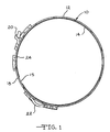
- the double-wrap band includes a strap member 10 which is composed of three bands 12A, 12B, 12C, longitudinally aligned and generally parallel to each other, forming a generally annular configuration.
- the preferable gauge of the material from which the strap member 10 is formed lies in the range of ⁇ 101 cm (.040 inch) to ⁇ 254 cm (.100 inch).
- the material used for the strap member 10 is MartINSiteTM steel, manufactured by the Inland Steel Corporation, in the gauge of ⁇ 152 cm (.060 inch). As shown in Fig.
- a friction lining 14 is adhered to the inner peripheral surface 15 of the three bands 12 by an acceptable method.
- a bracket member 16 is adhered to the outer peripheral surface 18 of the strap member 10.
- the bracket member 16 is preferably formed from 1536 SAE heat treated steel or, alternatively, HSLA non-heat treated steel.
- the bracket member 16 incorporates together an apply member 20 as shown in Figs. 1 and 2, a reaction member 22 as shown in Figs. 1 and 2, and a connector member 24 as shown in Figs. 1 and 2.
- the three bracket members 20, 22, 24 are, preferably, integrally interconnected, as shown in Figs. 5 and 6 by tie members 26.
- the apply member 20, reaction member 22 and connector member 24 may be individual components designed to be attached to the strap member 10.
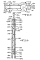
- Fig. 3 the structure of the strap member 10 utilized to secure the bracket member 16 to the strap member 10 is shown.
- the strap member 10 is manufactured so that the three generally parallel band members 12A, 12B, 12C are separated by longitudinally extending slots 28 which are separated by transversely aligned ties 30.
- One end 32B of the middle band member 12B extends beyond the ends 32A, 32C of the outside band members 12A, 1 2C.
- the opposed ends 34A, 34C of the outside band members 12A, 12C extend beyond the opposed end 34B of the middle band member 12B.
- Longitudinally oriented oval shaped slots 36 are located on the three band members 12A, 12B, 12C, extending therethrough.
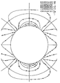
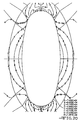
- the slots 36 are of a generally squared oval configuration and extend longitudinally along the band members 12A, 12B, 12C to prevent any potential interference with the cross-sectional strength of the individual band members. As shown by the stress contours of Fig. 17, this longitudinal orientation, coupled with the shape of the slot serves to spread the stresses encountered by the slots over a large surface area, thereby greatly reducing the potential for premature failure of the brake band.
- the stress contours shown in Fig. 17 indicate that the highest stresses, occurring around the oval slot as the result of an application of a 450 kg (1000 pound) load in the principal direction, are found at contour lines A and are stretching forces equivalent to 8.478E + 04 on 585 MPa (84,780 psi). This is comparatively lower than the round hole of Fig. 16 wherein the contour lines A are much more pronounced for the same applied load, showing stretching forces of 1.099E+05 or 758 MPa (109,900 psi).
- each slot 36 is, preferably, coined or stamped around its perimeter 38 to prestress the material around the perimeter of the slot 36, thereby enhancing the strength of the perimeter and limiting any stress fractures, which may occur during use of the band, to the prestressed perimeter 38 thereby preventing such stress fractures from progressing into the body of each band member 12A, 12B, 12C.
- the holes 37 to which the apply member 20 is attached are generally circular in shape and coined. However, it is envisioned that the shape of the holes 37 may also be designed in any shape to accommodate the stresses intended to be encountered by the apply bracket.
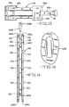
- a one-piece bracket member 16 intended for use with the strap member 10 of Fig. 3 is shown in detail.
- the one-piece bracket member 16 may not be preferred in some applications and three individual elements - apply, reaction and connector members may be substituted, if desired.
- the bracket member 16 will be described as "one-piece”.
- the one-piece bracket member 16 is formed to have generally the same radial curvature as the strap member 10.
- the one-piece bracket member 16 includes a reaction member 22, apply member 20, and connector member 24.
- the bracket member 16 includes a plurality of oval shaped longitudinal extrusions 40 located in the reaction member 22 and connector member 24.
- the apply member 20 includes a pair of circular extrusions 41.
- the extrusions 40, 41 are formed by locally extruding the bracket material through the inner peripheral surface 42 of the bracket member 16 to create a series of tabs 44.
- the tabs 44 are designed to mate with the slots 36 and hole 37 of the strap member 10 and extend therethrough.
- the tabs 44 may be tapered along their longitudinal sides 46 to enhance the ability of the tabs 44 to mate with the slots 36 and correctly position the bracket member 16 upon the strap member 10.
- the preferable clearance between the sides 46 of the tab 44 and the slot perimeter 38, after the bracket member 16 is correctly positioned upon the strap member 10, is ⁇ 038 mm (.0015 inches)/side. Further, as shown in detail in Fig.
- bracket member 16 is extruded so that the ends 48 of the longitudinally oriented oval extrusion are sunken deeper into the strap material to produce an extruded tab 44 having a longitudinal radial curvature which substantially parallels the radius of the strap member 10.
- the extruded tabs 44 extend evenly through the material of the strap member 10, the fastening forces of the extruded tabs 44 are evenly distributed and enhanced, to prevent shearing of the extrusion during loading.
- the tabs 44 are clinched in any acceptable manner.
- the tabs 44 may be clinched by use of a longitudinally oriented centre line punch which cold-punches the tab 44 and spreads the portion of the tab extending through the slot 36 into an expanded and engaged position with the slot perimeter 38.
- the expanded tab will commonly form a bead which extends ⁇ 05- ⁇ 075 mm (2-3 mil) outside of the inner perimeter 15 of the strap member 10.
- the friction liner 14 is removed at the areas where the bead extends beyond the inner perimeter, thereby providing smooth engagement of the friction facing with the clutch drum.
- the tie members 26 are eliminated, thus separating the apply member 20, reaction member 22 and connector member 24.
- the transversely aligned ties 30 located between the band members 12A, 12B, and 12C are also eliminated.
- the only interconnection between the three ends, 12A, 12B, 12C, is through the connector member 24 which is engaged to the slots 36 located in the end 32B of the middle band 12B and the opposed ends 34A and 34B of the outside bands 12A, 12C.
- the engagement between the bracket member 16 and strap member 10 may be further enhanced by providing a structural adhesive, such an epoxy which cures at the bonding temperature, the interface between the bracket member 16 and strap member 10.
- the strap member 110 is generally manufactured to have the same structure as the strap member of Fig. 3.
- One end 132B of the middle band member 112B extends beyond the ends 132A, 132C of the outside band members 112A, 112C.
- the opposed ends 134A, 134C of the outside band members 112A, 112C extend beyond the opposed end 134B of the middle band member 112B.
- Longitudinally oriented elliptical slots 136 are located on the three band members 112A, 112B, 112C, extending therethrough. As shown in Fig. 18, the elliptical slots 136 are designed to spread the stresses encountered by the slots over a large surface area, thereby greatly reducing the potential premature failure of the brake band.
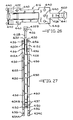
- the stress contours shown in Fig. 18 indicate that the highest stretching force felt by the ellipse at contour lines A are equivalent to 7.65E + 04 or 526 MPa (76,350 psi). As with the embodiment shown in Fig.
- each slot 136 may be coined around its perimeter (not shown) to prestress the material around the perimeter of the slot 136 thereby providing the ability to limit any stress fractures which may occur in the prestressed perimeter during use of the band and prevent such stress fractures from progressing into the body of each band member 112A, 112B, 112C.
- the holes 137 to which the apply member 120 is attached are generally circular in shape and coined. However, it is envisioned that such holes 137 may be designed to be longitudinal and elliptical in shape as are the remaining slots 136.
- the bracket member 116 has generally the same structure as the bracket member 16 described earlier with reference to Fig. 5 and is formed to have generally the same radial curvature as the strap member 110.
- the bracket member 116 includes a reaction member 122, apply member 120 and connector member 124.
- the bracket member 116 includes a plurality of elliptically shaped longitudinal extrusions 140 located in the reaction member 122 and connector member 124.
- the apply member 120 includes a pair of circular extrusions 141.
- the extrusions 140, 141 are formed by locally extruding the bracket material through the inner peripheral surface (not shown) of the bracket member 116 to create a series of tabs (not shown).
- the tabs are designed to mate with the slots 136 and holes 137 of the strap member 110 and extend therethrough.
- the tabs preferably have a clearance of ⁇ 0.38 mm (.0015 inches) per side with the slots 136, 137 to enhance the positioning of the bracket member 116 upon the strap member 110.
- the extruded tab members have the structural detail as described and shown in Fig. 7 and the manner in which the tabs are clinched to form a bead and fix the bracket member 116 to the strap member 110 is the same as that described earlier.
- the strap member 510 is generally manufactured to have the same structure as the strap member of Fig. 3.
- One end 532B of the middle band member 512B extends beyond the ends 532A, 532C of the outside band member 512A, 512C.
- the opposed ends 534A, 534C of the outside band members 512A, 512C extend beyond opposed end 534B of the middle band member 512B.
- the boat-shaped slot 536 is a hybrid longitudinal slot formed from an elliptical curve 535 on one end and an oval curve 537 on the opposed end of the slot.
- the hybrid boat-shape 536 formed from an elliptical curve 535 and an oval curve 537 is designed to accommodate high stress levels at the rear of the connection with respect to the load applied. It has been noted that an elliptical shape does not fare well when subjected to brute force gross overloading in that the narrow curve of the ellipse tends to shear off at a 45 degree angle.
- the boat-shaped hybrid 536 as shown in Fig. 12 creates a design wherein the oval curve 537 presents a larger area to counteract the shear forces and an elliptical tapered section 535 where the strap stress is multiplied in a non-shear fashion.
- the boat-shaped slots 536 will accommodate the stresses encountered by the slot in a different manner at each specified curved end of the slot. The stress contours shown in Fig.
- each slot 536 may be coined about its perimeter (not shown) to prestress the material around the perimeter of the slot 536 thereby providing the ability to limit any stress fractures which may occur in the prestressed perimeter during use of the band and preventing such fractures from progressing into the body of each band member 512A, 512B, 512C.
- the holes 537 to which the apply member 520 is attached are generally circular in shape and coined. However, it is envisioned that such holes 537 may be designed to be longitudinal and boat-shaped as are the remaining slots 536.
- the bracket member 516 has generally the same structure as the bracket member 16 described earlier with reference to Fig. 5 and is formed to have the same radial curvature as the strap member 510.
- the bracket member 516 includes a reaction member 522, apply member 520 and connector member 524.
- the bracket member 516 includes a plurality of boat-shaped longitudinal extrusions 540 located in the reaction member 522 and a connector member 524.
- the apply member 520 includes a pair of circular extrusions 541.
- the extrusions 540, 541 are formed by locally extruding the bracket material through the inner peripheral surface (not shown) of the bracket member 516 to create a series of tabs (not shown).
- the tabs are designed to mate with the slots 536 and holes 537 of the strap member 510 and extend therethrough.
- the tabs preferably have a clearance of ⁇ 038 mm (.0015 inches) per side with the slots 536, 537 to enhance the positioning of the bracket member 516 upon the strap member 510.
- the extruded tab members have the structural detail described and shown in Fig. 7 and the manner in which the tabs are clinched to form a bead and fix the bracket member 516 to the strap member 510 is the same as that described earlier.
- a third embodiment of a one-piece bracket member 616 and corresponding strap member 610 is shown.
- the strap member 610 is generally manufactured to have the same structure as the strap member of Fig. 3.
- One end 632B of the middle band member 612B extends beyond the ends 632A, 632C of the outside band members 612A, 612C.
- the opposed ends 634A, 634C of the outside band members 612A, 612C extend beyond the opposed end 6348 of the middle band member 612B.
- Longitudinally oriented elliptically shaped slots with oval shaped ends 636 are located on the three band members 612A, 612B, 612C, extending therethrough. As shown in Fig. 15, the elliptical slots 636 have oval shaped ends which are designed to spread the stresses encountered by the slots over a large surface area, thereby greatly reducing the potential premature failure of the brake band.
- the stress contours shown in Fig. 20 indicated that the highest stretching forces felt by the ellipse with oval ends at contour lines A are equivalent to 7.499E + 04 or 517 MPa (74,990 psi). As with the embodiment shown in Fig.
- each slot 636 may be coined about its perimeter (not shown) to prestress the material around the perimeter of the slots 636 thereby providing the ability to limit any stress fractures which may occur in the prestressed perimeter during use ofthe band and preventing such stress fractures from progressing into the body of each band member 612A, 612B, 612C.
- the holes 637 to which the apply member 620 are attached are generally circular in shape and coined. However, it is envisioned that such holes 637 may be designed to longitudinal and elliptical shaped with oval curves as are the remaining slots 636.
- the bracket member 616 has generally the same structure as the bracket member 16 described earlier with reference to Fig. 5 and is formed to have generally the same radial curvature as the strap member 610.
- the bracket member 616 includes a reaction member 622, apply member 620, and connector member 624.
- the bracket member 616 includes a plurality of elliptically shaped longitudinal extrusions having oval curves 640 located in the reaction member 622 and connector member 624.
- the apply member 620 includes a pair of circular extrusions 641.
- the extrusions 640, 641 are formed by locally extruding the bracket material through the inner peripheral surface (not shown) of the bracket member 616 to create a series of tabs (not shown).
- the tabs are designed to mate with the slots 636 and holes 637 of the strap member 610 and extend therethrough.
- the tabs preferably have a clearance of ⁇ 038 mm (.0015 inches) per side with the slots 636, 637 to enhance the positioning of the bracket member 616 upon the strap member 610.
- the extruded tab members may have the same structural detail as described and shown in Fig. 7 and the manner in which the tabs are clinched to form a bead and fix the bracket member 616 to the strap member 610 is the same as that discussed earlier.
- a fourth embodiment of a one-piece bracket member 216 and the corresponding strap member 210 is shown.
- the strap member 210 is generally manufactured to have the same structure as the embodiments described earlier with reference to Fig. 3.
- the longitudinally oriented slots 236, however, are diamond shaped.
- the slots 236 have a minor radial curve 239 as shown in Fig. 23 at each of the four corners of the diamond shape.
- the longitudinal orientation coupled with the diamond shape of the slots 236 and the radial curve at the corners of the slots 236 serves to spread the stresses encountered by each slot 236 over a larger surface area, thereby greatly reducing the potential for premature failure of the brake band.
- each of the slots 236 may be coined about the perimeter as has been described earlier with regard to Fig. 3.
- the holes 237 to which the apply member 220 is attached are generally circular in shape, and, preferably, coined. However, it is envisioned that such holes 237 may also be designed to be diamond shaped as are the remaining slots 236.
- the bracket member 216 is generally structured in the same manner as the bracket members described earlier with reference to Fig. 5.
- the extrusions 240 of the bracket member 216 are generally diamond shaped having a minor radial curve at each of the four corners so as to cleanly mate with the diamond shaped slots 236 of the band member 210 of Fig. 22.
- the structure of the extruded tabs preferably includes the same detail as that structure described earlier for those tabs referenced in Figs. 5-7 and the manner in which the tabs are clinched to form a bead and fix the bracket member 216 to the strap member 210 is the same as that described earlier.
- a fifth embodiment of a one-piece bracket member 316 and the corresponding strap member 310 is shown.
- the structure of the strap member 310 remains generally unchanged with the exception of the slots-328 having the shape of tear drops.
- the structure of the bracket member 316 remains generally unchanged from the structure described earlier with reference to Figs. 5-7.
- the bracket member 316 includes corresponding tear drop shaped extrusions 340 intended to mate with the slots 328 of the strap member 310.
- a sixth embodiment of a bracket member 416 and a corresponding strap member 410 is shown.
- the structure of the strap member 410 remains generally unchanged from the structure of the embodiments described earlier with reference to Fig. 3 with the exception of the slots 428 which are clover shaped.
- the structure of the bracket member 416 remains generally unchanged from the structure described earlier with reference to Figs. 5 - 7.
- the bracket member 416 includes corresponding clover shaped extrusions 440 intended to mate with the slots 428 of the strap member 410.
- the described and illustrated double-wrap brake bands embodying the invention provide the ability to maintain a lighter weight without reduced strength characteristics through the use of lighter gauge materials; simplify manufacturing operations and reduce complexities in manufacturing operations by eliminating the need for loose parts during the assembly process; provide for improved bracket alignment on the strap members; eliminate the need for heat treatment of the band assembly and, therefore, provide for better conformity of the band to the transmission drum; and, by eliminating the need for welding in the assembly process, reduce the distortion of the band assembly which otherwise would be caused by the extreme heat of welding.
Landscapes
- Engineering & Computer Science (AREA)
- General Engineering & Computer Science (AREA)
- Mechanical Engineering (AREA)
- Braking Arrangements (AREA)
- Clamps And Clips (AREA)
Description
Claims (7)
- A double-wrap brake band comprising a strap member (10; 110; 210; 310; 410; 510; 610) having three curved bands (12A, 12B, 12C; 112A, 112B, 112C; 212A, 212B, 212C; 312A, 312B, 312C; 412A, 412B, 412C; 512A, 512B, 512C; 612A, 612B, 612C) of a specified thickness joined together in a generally parallel relationship by a bracket member (16; 116; 216; 316; 416; 516; 616) having an annular inner peripheral surface (42) to form a substantially annular configuration; said bracket member having a connector member (24; 124; 224; 324; 424; 524; 624) joined to the ends of all three bands, an apply member (20; 120; 220; 320; 420; 520; 620) secured to the end (34B; 134B; 234B; 334B; 434B; 534B; 634B) of the central band member (12B; 112B; 212B; 312B; 412B; 512B; 612B), and a reaction member (22; 122; 222; 322; 422; 522; 622) secured to the ends (32A, 32C; 132A, 132C; 232A, 232C; 332A, 332C; 432A, 432C; 532A, 532C; 632A, 632C) of the outside band members (12A, 12C; 112A, 112C; 212A, 212C; 312A, 312C; 412A, 412C; 512A, 512C; 612A, 612C); wherein said strap member includes a plurality of slots (36; 136; 236; 336; 436; 536; 636) extending therethrough; characterized in that each slot is non-circular, longitudinally oriented on said strap member and defines a perimeter edge (38), said bracket member includes a plurality of extruded non-circular tabs (44) extending from the inner peripheral surface of said bracket member for positioning within said slots to engage said slots and extend beyond an inner peripheral surface (15) of said strap member, whereby said tabs extending beyond said inner peripheral surface of said strap member are clinched and are pressed into engagement with the perimeter edges of said slots to secure said bracket member to said strap member; anda) said slots (136) are elliptical-shaped, such elliptical shape being longitudinally oriented on said strap member (110), and said tabs have an elliptical-shape designed to mate with said elliptical-shaped slots (136); orb) said slots (236) are generally diamond-shaped and said tabs are generally diamond-shaped and designed to mate with said slots (236); orc) said slots (336) are generally tear drop shaped, such tear drop shape being longitudinally oriented on said strap member (310), and said tabs have a tear drop shape designed to mate with said tear drop shaped slots (336); ord) said slots (446) are generally clover-shaped and said tabs have a clover shape designed to mate with said clover-shaped slots (436); ore) said slots (536) are boat-shaped having an elliptical curve (535) at one end of such longitudinally oriented slot and an oval curve (537) at the opposed end of such slot and said tabs have a boat shape designed to mate with said boat-shaped slots (536); orf) said slots (636) are elliptical in shape with oval-like curves located at each end of such longitudinal elliptical slot and said tabs have a matching shape designed to mate with said slots (636).
- A brake band as claimed in claim 1, wherein said diamond-shape of said slots (236) and tabs includes small radial curves located at the apexes of said diamond shape.
- A brake band as claimed in claim 1 or claim 2, wherein each of said slots (36) is prestressed about its perimeter (33).
- A brake band as claimed in any of the preceding claims, wherein said tabs (44) continue to extend beyond the inner peripheral surface (15) of said strap member (10), after said tabs (44) are clinched to said strap member (10) and pressed into engagement with the perimeters (38) of said slots (36), such extension being less than 3 mil.
- A brake band as claimed in any of the preceding claims, wherein said tabs (44) are each extruded such that each of said tabs (44) has a longitudinal curvature that is substantially radially parallel to the annular inner peripheral surface (42) of said bracket member (16) and the curvature of said strap member (10).
- A brake band as claimed in any of claims 1 to 4, wherein said tabs (44) have longitudinally oriented sides that are tapered inward from the inner peripheral surface (42) of said bracket member (16).
- A brake band as claimed in any of the preceding claims, wherein said apply member (20), said reaction member (22), and said connector member (24) are structurally independent components.
Applications Claiming Priority (4)
| Application Number | Priority Date | Filing Date | Title |
|---|---|---|---|
| US632493A | 1993-01-19 | 1993-01-19 | |
| US6324 | 1993-01-19 | ||
| US162495 | 1993-12-03 | ||
| US08/162,495 US5476160A (en) | 1991-10-29 | 1993-12-03 | Double-wrap brake band assembly |
Publications (2)
| Publication Number | Publication Date |
|---|---|
| EP0607698A1 EP0607698A1 (en) | 1994-07-27 |
| EP0607698B1 true EP0607698B1 (en) | 1998-03-18 |
Family
ID=26675481
Family Applications (1)
| Application Number | Title | Priority Date | Filing Date |
|---|---|---|---|
| EP93310494A Expired - Lifetime EP0607698B1 (en) | 1993-01-19 | 1993-12-23 | Double-wrap brake band assembly |
Country Status (5)
| Country | Link |
|---|---|
| US (1) | US5476160A (en) |
| EP (1) | EP0607698B1 (en) |
| JP (1) | JPH06235433A (en) |
| KR (1) | KR100329687B1 (en) |
| DE (1) | DE69317542T2 (en) |
Families Citing this family (8)
| Publication number | Priority date | Publication date | Assignee | Title |
|---|---|---|---|---|
| JP4054122B2 (en) * | 1998-11-26 | 2008-02-27 | Nskワーナー株式会社 | Double wound brake band device |
| JP4349704B2 (en) * | 1999-11-12 | 2009-10-21 | Nskワーナー株式会社 | Double wound band brake device |
| US20010008196A1 (en) | 2000-01-13 | 2001-07-19 | Kazuyuki Fujita | Band braking device, and method of manufacturing annular brake band |
| JP4579467B2 (en) * | 2001-08-23 | 2010-11-10 | Nskワーナー株式会社 | Double winding band brake device |
| JP4117185B2 (en) * | 2002-12-03 | 2008-07-16 | Nskワーナー株式会社 | Double winding band brake device |
| JP4088197B2 (en) | 2003-05-08 | 2008-05-21 | Nskワーナー株式会社 | Double winding band brake device |
| JP4553672B2 (en) * | 2004-10-08 | 2010-09-29 | Nskワーナー株式会社 | Brake band |
| US20080240849A1 (en) * | 2007-03-30 | 2008-10-02 | Robert Lindemann | Non-marring shaft collar |
Family Cites Families (23)
| Publication number | Priority date | Publication date | Assignee | Title |
|---|---|---|---|---|
| US2663270A (en) * | 1949-05-25 | 1953-12-22 | Gregory Ind Inc | Composite stud |
| US2867898A (en) * | 1954-06-28 | 1959-01-13 | Gen Motors Corp | Method of manufacturing a brake band |
| US2841864A (en) * | 1955-05-23 | 1958-07-08 | Kelsey Hayes Co | Method of making friction band assemblies |
| US2958230A (en) * | 1958-02-04 | 1960-11-01 | Haroldson Victor Gottfrid | Fastener structure for pulleys and the like |
| US3265166A (en) * | 1964-08-31 | 1966-08-09 | Bendix Corp | Brake shoe |
| US3386535A (en) * | 1966-10-26 | 1968-06-04 | Gen Motors Corp | Friction band |
| US3399749A (en) * | 1966-10-31 | 1968-09-03 | Borg Warner | Flexible resilient brake band |
| US3828517A (en) * | 1971-10-27 | 1974-08-13 | V Johnson | Metal layer rivetform and two layer assembly |
| DE2532349B2 (en) * | 1975-07-19 | 1979-08-30 | Stieber Division Der Borg-Warner Gmbh, 6900 Heidelberg | Resilient brake band of the flexible design provided with a brake lining |
| FR2376338A1 (en) * | 1976-12-30 | 1978-07-28 | Borg Warner Stieber Gmbh | Brake band for rotary drum - consists of steel strip with friction lining and holding shoes at ends |
| US4363385A (en) * | 1980-07-28 | 1982-12-14 | Alfred Schlanger | Transmission brake band end connection |
| US4581803A (en) * | 1981-10-09 | 1986-04-15 | Borg-Warner Corporation | Method of forming double wrap brake bands |
| US4602706A (en) * | 1981-10-09 | 1986-07-29 | Borg-Warner Corporation | Double wrap brake band |
| CA1248885A (en) * | 1984-09-06 | 1989-01-17 | Borg-Warner Corporation | Strap configuration for a double wrap band |
| CA1248884A (en) * | 1984-09-06 | 1989-01-17 | Borg-Warner Corporation | Bracket assembly for a double wrap band |
| US4757880A (en) * | 1985-11-21 | 1988-07-19 | Borg-Warner Automotive, Inc. | Strap configuration for a reverse double wrap band |
| JP2706462B2 (en) * | 1988-03-29 | 1998-01-28 | ジャトコ株式会社 | Brake band |
| JPH0276934A (en) * | 1988-09-12 | 1990-03-16 | Daikin Mfg Co Ltd | Laminated winding brake band and manufacture thereof |
| US5083642A (en) * | 1990-01-25 | 1992-01-28 | Advanced Friction Materials Company | Double wrap friction brake band and method of manufacture |
| US5346040A (en) * | 1990-04-12 | 1994-09-13 | Borg-Warner Automotive Transmission & Engine Components Corporation | One-piece transmission band |
| CA2076325A1 (en) * | 1991-10-29 | 1993-04-30 | Anthony J. Grzesiak | Double-wrap brake band assembly |
| AU2700192A (en) * | 1991-11-26 | 1993-05-27 | Borg-Warner Automotive Transmission & Engine Components Corporation | Improved anchor in automatic transmission bands |
| FR2693894B1 (en) * | 1992-07-24 | 1994-09-30 | Seb Sa | Method for modifying the characteristics of a metal surface. |
-
1993
- 1993-12-03 US US08/162,495 patent/US5476160A/en not_active Expired - Lifetime
- 1993-12-23 EP EP93310494A patent/EP0607698B1/en not_active Expired - Lifetime
- 1993-12-23 DE DE69317542T patent/DE69317542T2/en not_active Expired - Lifetime
- 1993-12-28 JP JP5334782A patent/JPH06235433A/en active Pending
-
1994
- 1994-01-19 KR KR1019940000912A patent/KR100329687B1/en not_active Expired - Fee Related
Also Published As
| Publication number | Publication date |
|---|---|
| EP0607698A1 (en) | 1994-07-27 |
| DE69317542D1 (en) | 1998-04-23 |
| DE69317542T2 (en) | 1998-07-09 |
| KR940018582A (en) | 1994-08-18 |
| KR100329687B1 (en) | 2002-11-18 |
| US5476160A (en) | 1995-12-19 |
| JPH06235433A (en) | 1994-08-23 |
Similar Documents
| Publication | Publication Date | Title |
|---|---|---|
| US5067227A (en) | Double wrap brake band and its manufacturing method | |
| EP0230727B1 (en) | Strap configuration for a reverse double wrap band | |
| US5476160A (en) | Double-wrap brake band assembly | |
| US4602706A (en) | Double wrap brake band | |
| AU2003221811A1 (en) | Composite sprocket | |
| EP0512044B1 (en) | Double wrap friction band | |
| WO1991002176A1 (en) | Elastomeric vibrational dampers | |
| EP0491292B1 (en) | Clamping band | |
| JP3053257B2 (en) | Brake band for transmission and method of manufacturing the same | |
| EP0540156B1 (en) | Double-wrap brake band assembly | |
| KR930011877B1 (en) | Friction member for clutch plate and clutch plate assembly using same | |
| EP0180389B1 (en) | Friction components for clutch plates and the like | |
| US4581803A (en) | Method of forming double wrap brake bands | |
| US5381876A (en) | Anchor in automatic transmission bands | |
| US5346040A (en) | One-piece transmission band | |
| US4915531A (en) | Disc clutch | |
| JP3942663B2 (en) | Brake band | |
| EP0520614B1 (en) | One-piece transmission band | |
| EP0544406B1 (en) | Improved anchor in automatic transmission bands | |
| JPH10132052A (en) | Drive plate structure made of sheet metal | |
| CA1248883A (en) | Bracket assembly for a double wrap band | |
| CA1248885A (en) | Strap configuration for a double wrap band | |
| US5347702A (en) | Method of producing a transmission brake band | |
| JPH0942333A (en) | Brake band | |
| AU6145090A (en) | Elastomeric vibrational dampers |
Legal Events
| Date | Code | Title | Description |
|---|---|---|---|
| PUAI | Public reference made under article 153(3) epc to a published international application that has entered the european phase |
Free format text: ORIGINAL CODE: 0009012 |
|
| AK | Designated contracting states |
Kind code of ref document: A1 Designated state(s): DE FR GB |
|
| 17P | Request for examination filed |
Effective date: 19941207 |
|
| 17Q | First examination report despatched |
Effective date: 19950905 |
|
| GRAG | Despatch of communication of intention to grant |
Free format text: ORIGINAL CODE: EPIDOS AGRA |
|
| GRAG | Despatch of communication of intention to grant |
Free format text: ORIGINAL CODE: EPIDOS AGRA |
|
| GRAH | Despatch of communication of intention to grant a patent |
Free format text: ORIGINAL CODE: EPIDOS IGRA |
|
| GRAH | Despatch of communication of intention to grant a patent |
Free format text: ORIGINAL CODE: EPIDOS IGRA |
|
| GRAA | (expected) grant |
Free format text: ORIGINAL CODE: 0009210 |
|
| AK | Designated contracting states |
Kind code of ref document: B1 Designated state(s): DE FR GB |
|
| REF | Corresponds to: |
Ref document number: 69317542 Country of ref document: DE Date of ref document: 19980423 |
|
| ET | Fr: translation filed | ||
| PLBE | No opposition filed within time limit |
Free format text: ORIGINAL CODE: 0009261 |
|
| STAA | Information on the status of an ep patent application or granted ep patent |
Free format text: STATUS: NO OPPOSITION FILED WITHIN TIME LIMIT |
|
| 26N | No opposition filed | ||
| REG | Reference to a national code |
Ref country code: GB Ref legal event code: IF02 |
|
| PGFP | Annual fee paid to national office [announced via postgrant information from national office to epo] |
Ref country code: GB Payment date: 20091106 Year of fee payment: 17 Ref country code: FR Payment date: 20091215 Year of fee payment: 17 |
|
| PGFP | Annual fee paid to national office [announced via postgrant information from national office to epo] |
Ref country code: DE Payment date: 20091230 Year of fee payment: 17 |
|
| GBPC | Gb: european patent ceased through non-payment of renewal fee |
Effective date: 20101223 |
|
| REG | Reference to a national code |
Ref country code: FR Ref legal event code: ST Effective date: 20110831 |
|
| PG25 | Lapsed in a contracting state [announced via postgrant information from national office to epo] |
Ref country code: FR Free format text: LAPSE BECAUSE OF NON-PAYMENT OF DUE FEES Effective date: 20110103 |
|
| REG | Reference to a national code |
Ref country code: DE Ref legal event code: R119 Ref document number: 69317542 Country of ref document: DE Effective date: 20110701 |
|
| PG25 | Lapsed in a contracting state [announced via postgrant information from national office to epo] |
Ref country code: GB Free format text: LAPSE BECAUSE OF NON-PAYMENT OF DUE FEES Effective date: 20101223 Ref country code: DE Free format text: LAPSE BECAUSE OF NON-PAYMENT OF DUE FEES Effective date: 20110701 |