EP0606412B1 - Medical device - Google Patents
Medical device Download PDFInfo
- Publication number
- EP0606412B1 EP0606412B1 EP93910490A EP93910490A EP0606412B1 EP 0606412 B1 EP0606412 B1 EP 0606412B1 EP 93910490 A EP93910490 A EP 93910490A EP 93910490 A EP93910490 A EP 93910490A EP 0606412 B1 EP0606412 B1 EP 0606412B1
- Authority
- EP
- European Patent Office
- Prior art keywords
- electrode
- electrodes
- skin
- electrode plate
- electrode tip
- Prior art date
- Legal status (The legal status is an assumption and is not a legal conclusion. Google has not performed a legal analysis and makes no representation as to the accuracy of the status listed.)
- Expired - Lifetime
Links
- 210000003491 skin Anatomy 0.000 claims abstract description 84
- 208000002193 Pain Diseases 0.000 claims abstract description 20
- 230000036407 pain Effects 0.000 claims abstract description 20
- 208000003251 Pruritus Diseases 0.000 claims abstract description 16
- 230000035515 penetration Effects 0.000 claims abstract description 12
- 210000001519 tissue Anatomy 0.000 claims abstract description 11
- 230000037023 motor activity Effects 0.000 claims abstract description 8
- 210000002615 epidermis Anatomy 0.000 claims abstract description 7
- 239000008280 blood Substances 0.000 claims abstract description 5
- 210000004369 blood Anatomy 0.000 claims abstract description 5
- 230000001684 chronic effect Effects 0.000 claims abstract description 5
- 230000001154 acute effect Effects 0.000 claims abstract description 4
- 230000004936 stimulating effect Effects 0.000 claims description 6
- 238000013461 design Methods 0.000 claims description 3
- 230000000638 stimulation Effects 0.000 description 24
- 108020003175 receptors Proteins 0.000 description 19
- 210000005036 nerve Anatomy 0.000 description 18
- 238000002646 transcutaneous electrical nerve stimulation Methods 0.000 description 9
- 230000037368 penetrate the skin Effects 0.000 description 7
- 210000000412 mechanoreceptor Anatomy 0.000 description 6
- 108091008704 mechanoreceptors Proteins 0.000 description 6
- 210000003205 muscle Anatomy 0.000 description 6
- 230000003213 activating effect Effects 0.000 description 5
- 238000001467 acupuncture Methods 0.000 description 5
- 210000000929 nociceptor Anatomy 0.000 description 5
- 230000000694 effects Effects 0.000 description 4
- 108091008700 nociceptors Proteins 0.000 description 4
- 230000004913 activation Effects 0.000 description 3
- 230000000202 analgesic effect Effects 0.000 description 3
- 210000004207 dermis Anatomy 0.000 description 3
- 230000002401 inhibitory effect Effects 0.000 description 3
- 239000012212 insulator Substances 0.000 description 3
- 239000000463 material Substances 0.000 description 3
- 239000011159 matrix material Substances 0.000 description 3
- 210000002569 neuron Anatomy 0.000 description 3
- NTYJJOPFIAHURM-UHFFFAOYSA-N Histamine Chemical compound NCCC1=CN=CN1 NTYJJOPFIAHURM-UHFFFAOYSA-N 0.000 description 2
- 239000003638 chemical reducing agent Substances 0.000 description 2
- 239000004020 conductor Substances 0.000 description 2
- 230000008602 contraction Effects 0.000 description 2
- 230000002045 lasting effect Effects 0.000 description 2
- 230000007246 mechanism Effects 0.000 description 2
- 238000000034 method Methods 0.000 description 2
- 230000035807 sensation Effects 0.000 description 2
- 210000000225 synapse Anatomy 0.000 description 2
- 238000012360 testing method Methods 0.000 description 2
- 208000000112 Myalgia Diseases 0.000 description 1
- 208000000114 Pain Threshold Diseases 0.000 description 1
- 206010033799 Paralysis Diseases 0.000 description 1
- 208000028990 Skin injury Diseases 0.000 description 1
- 208000002240 Tennis Elbow Diseases 0.000 description 1
- 208000027418 Wounds and injury Diseases 0.000 description 1
- 230000004308 accommodation Effects 0.000 description 1
- 210000003050 axon Anatomy 0.000 description 1
- 230000017531 blood circulation Effects 0.000 description 1
- 210000004556 brain Anatomy 0.000 description 1
- 210000004027 cell Anatomy 0.000 description 1
- 230000006378 damage Effects 0.000 description 1
- 238000011156 evaluation Methods 0.000 description 1
- 239000000835 fiber Substances 0.000 description 1
- 229960001340 histamine Drugs 0.000 description 1
- 238000002347 injection Methods 0.000 description 1
- 239000007924 injection Substances 0.000 description 1
- 208000014674 injury Diseases 0.000 description 1
- 239000011810 insulating material Substances 0.000 description 1
- 230000003993 interaction Effects 0.000 description 1
- 210000003127 knee Anatomy 0.000 description 1
- 230000007774 longterm Effects 0.000 description 1
- 208000013465 muscle pain Diseases 0.000 description 1
- 230000003387 muscular Effects 0.000 description 1
- 230000001537 neural effect Effects 0.000 description 1
- 230000037040 pain threshold Effects 0.000 description 1
- 210000000578 peripheral nerve Anatomy 0.000 description 1
- 238000011160 research Methods 0.000 description 1
- 238000006748 scratching Methods 0.000 description 1
- 230000002393 scratching effect Effects 0.000 description 1
- 230000015541 sensory perception of touch Effects 0.000 description 1
- 229920002379 silicone rubber Polymers 0.000 description 1
- 125000006850 spacer group Chemical group 0.000 description 1
- 210000000434 stratum corneum Anatomy 0.000 description 1
- 210000000439 stratum lucidum Anatomy 0.000 description 1
- 230000001360 synchronised effect Effects 0.000 description 1
- 239000003106 tissue adhesive Substances 0.000 description 1
- 238000012546 transfer Methods 0.000 description 1
Images
Classifications
-
- A—HUMAN NECESSITIES
- A61—MEDICAL OR VETERINARY SCIENCE; HYGIENE
- A61N—ELECTROTHERAPY; MAGNETOTHERAPY; RADIATION THERAPY; ULTRASOUND THERAPY
- A61N1/00—Electrotherapy; Circuits therefor
- A61N1/18—Applying electric currents by contact electrodes
- A61N1/32—Applying electric currents by contact electrodes alternating or intermittent currents
- A61N1/36—Applying electric currents by contact electrodes alternating or intermittent currents for stimulation
- A61N1/36014—External stimulators, e.g. with patch electrodes
- A61N1/36021—External stimulators, e.g. with patch electrodes for treatment of pain
-
- A—HUMAN NECESSITIES
- A61—MEDICAL OR VETERINARY SCIENCE; HYGIENE
- A61N—ELECTROTHERAPY; MAGNETOTHERAPY; RADIATION THERAPY; ULTRASOUND THERAPY
- A61N1/00—Electrotherapy; Circuits therefor
- A61N1/02—Details
- A61N1/04—Electrodes
- A61N1/0404—Electrodes for external use
- A61N1/0472—Structure-related aspects
-
- A—HUMAN NECESSITIES
- A61—MEDICAL OR VETERINARY SCIENCE; HYGIENE
- A61N—ELECTROTHERAPY; MAGNETOTHERAPY; RADIATION THERAPY; ULTRASOUND THERAPY
- A61N1/00—Electrotherapy; Circuits therefor
- A61N1/18—Applying electric currents by contact electrodes
- A61N1/20—Applying electric currents by contact electrodes continuous direct currents
- A61N1/205—Applying electric currents by contact electrodes continuous direct currents for promoting a biological process
-
- A—HUMAN NECESSITIES
- A61—MEDICAL OR VETERINARY SCIENCE; HYGIENE
- A61N—ELECTROTHERAPY; MAGNETOTHERAPY; RADIATION THERAPY; ULTRASOUND THERAPY
- A61N1/00—Electrotherapy; Circuits therefor
- A61N1/18—Applying electric currents by contact electrodes
- A61N1/32—Applying electric currents by contact electrodes alternating or intermittent currents
- A61N1/36—Applying electric currents by contact electrodes alternating or intermittent currents for stimulation
- A61N1/36014—External stimulators, e.g. with patch electrodes
- A61N1/36017—External stimulators, e.g. with patch electrodes with leads or electrodes penetrating the skin
Definitions
- the present invention relates to a device for relieving chronic and acute states of pain as well as itch, for affecting the motor activity of disabled people, or for increasing the flow-through of blood in underlying tissue.
- the device comprises a shapable electrode plate through which extend a plurality of electrodes which are fixed in the electrode plate and terminate, at their respective free ends, in an electrode tip portion for skin protection.
- thick myelinated nerve fibres from sensitive mechanoreceptors can be preferentially stimulated, having the lowest threshold for electrical stimulation. This method has been found to have analgetic effects for some states of pain in about 50% of the patients tested.
- pain-activated nerve cells as well as other nerve cells receiving information from the body surface, can be maximally activated from very small areas of the skin. Consequently, it is unnecessary, and probably wrong, to stimulate whole nerves supplying large receptor beds.
- the object of the present invention is to provide a device enabling specific stimulation of the receptors in the skin in order to relieve chronic and acute states of pain as well as itch, affect the motor activity of disabled people, or increase the flow-through of blood in underlying tissue.
- the inventive device differs from existing TENS apparatus by the stimulation being performed locally within a defined and functional area of the skin, TENS stimulating whole nerves which convey unspecific information from the skin as well as the underlying tissue. Since stimulation from multiple points can be performed consecutively, thus reaching individual skin receptors at a relatively low frequency, fatigue phenomena (accommodation) of individual inward-leading nerve fibres and their central synapses can be reduced. TENS, on the other hand, activate whole nerves, and consequently a large number of nerve fibres, which involves a pronounced fatigue phenomenon.
- TENS generates an unpleasant sensation of current owing to the synchronous activation of nerve fibres. This sensation often radiates along the distribution of the stimulated nerves.
- the inventive device initially gives rise to a local and brief pricking pain which largely can be eliminated by gradually increasing the intensity of the stimulation.
- the inventive device makes it possible to use a lower current intensity (6 mA at the most) than in TENS (30-60 mA).
- the voltage used in the invention (40 V at the most, usually below 20 V) is also much lower than that used in TENS (50-200 V). This reduces the risk of complications, e.g. for people with pacemakers.
- the present invention differs from acupuncture in the following way.
- acupuncture the skin is punctured by individual needles which penetrate the underlying tissue. Stimulation is brought about either by electrical current or by mechanical manipulation. Since the needles used are not insulated, current dissipates along the needles, resulting in an unspecific stimulation of receptors in the skin as well as deaper-lying tissue. Often, acupuncture also activates nearby nerves passing by. Thus, acupuncture differs from the present invention primarily by providing unspecific stimulation of different types of receptors along the needle and nearby nerves. Furthermore, the current intensity used in acupuncture is, as a rule, higher than that used in the invention.
- US patent 3,612,061 (Collins et al) relates to a flexible electrode matrix.
- the aim of this invention is to use the tactile sense of blind people for transmitting information.
- the US device consists of a flexible sheet or plate with electrodes placed in a matrix. Each electrode is connected to a separate, lying cable to a power supply unit. The sheet is earthed. The electrodes can be individually stimulated, and the electrode matrix may therefore be stimulated according to different patterns.
- Each electrode projects from the sheet and consists of a cylinder having a convex surface which is applied to the skin under pressure.
- the US device differs from the present invention in that the electrodes do not penetrate the skin. No parameters for the stimulation are indicated.
- the electrodes are apparently not intended to be stimulated consecutively, a spatial pattern being aimed at. Since the electrodes do not penetrate the skin, a higher voltage is needed for stimulating the skin receptors/nerves. As a result, the current dissipates to a larger extent and is less specific than in the present invention.
- US patent 4,982,743 (Pierson) relates to an itch reducer, which comprises an electrode sheet or plate (smaller than 4 cm 2 ) having projecting and blunt electrodes to be applied against the skin.
- the electrodes project 0.2-1.0 mm from the sheet.
- the electrode tips are not pointed and are only pressed slightly into the skin when the electrode head is applied against the skin surface.
- the US specification explicitly states that the electrodes do not penetrate or perforate the skin.
- the skin is stimulated by direct voltage (20 V at the most) for up to a minute or so. It is further indicated that the stimulation is not felt (i.e. does not noticeably activate the skin receptors) while the itch is relieved.
- the US itch reducer differs from the present invention in that the electrodes, as already stated, are not designed to penetrate the skin. Furthermore, direct current is used, and not pulsed stimulation. Unlike the inventive device, the US device does not provide any possibility of consecutively stimulating the different projecting electrodes. Finally, the size of the sheet is even smaller than 4 cm 2 .
- EP-A-0,377,057 (Bernardini et al) relates to a hand-operated electromedical device for analgetic skin treatment, more precisely a portable apparatus having four electrode pairs embedded in a plate.
- the electrodes which are blunt and shown as round in the accompanying drawing, do not penetrate the skin.
- the electrode pairs are stimulated at the same frequency. Any parameters for the stimulation are not indicated, neither are the dimensions of the apparatus.
- the EP apparatus differs from the inventive device in that the electrodes do not penetrate the skin and in that only a few electrode pairs are used. Further, it is not possible to stimulate these electrodes consecutively.
- the stimulation voltage should, in addition, be much higher in order to activate receptors/nerves, as in conventional TENS. Moreover, the current density does not become as high intracutaneously.
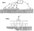
- an electrode plate 1 is provided with several electrodes 2 fixed in the plate 1 and extending therethrough. Each electrode 2 is connected to a control unit 4 by an electric line 3.
- the control unit 4 is in turn connected, by an electric line 5, to a collector electrode 6 of opposite electrical polarity to the electrodes 2.
- the electrode plate 1 with the electrodes 2 projecting from its underside, and the collector electrode 6 are applied to a skin portion 10 during the stimulation operation.
- the electrode plate 1 is shapable and substantially flat.
- the plate may be of different size, depending on the size of the skin portion to be stimulated.
- the plate is made of some conventional pliable material enabling it to be used on curved parts of the body, such as the elbows, the shoulders and the knees.
- the plate may be about 1-500 cm 2 , but preferably is about 4-300 cm 2 .
- the size of the plate depends on the skin area to be stimulated. Where the skin has low receptor density, fairly large areas have to be stimulated. For instance, comparatively large areas are stimulated on the back and the back of the head, while smaller areas are stimulated on the arms and the face.
- one or more electrode plates 1 may in addition be connected when large areas of the skin are to be stimulated. Electrically, the electrode plate 1 may be an insulator in its entirety or it may be made up of an insulator in the layer closest to the skin and, in an overlying layer, consist either of electrically conductive wires from the electrodes 2 to the control unit 4 or of printed board. In a preferred embodiment, the electrode plate 1 is a sleeve of silicon rubber.
- Electrodes 2 extend through recesses in the electrode plate 1 and project from the underside of the plate facing the skin portion 10, as shown in Fig. 2.
- the electrodes 2 are substantially elongate and are made of conventional conductive material.
- the upper end of each electrode 2 is connected to the control unit 4. This upper end may project from the upper side of the electrode plate 1 facing away from the skin portion or it may be embedded in the electrode plate 1.
- the electrode 2 ends in an electrode tip portion 7 intended to penetrate the skin portion 10. It is of considerable importance that the electrode tip portion 7 is so designed that it can penetrate the skin sufficiently to achieve the desired stimulation of the skin receptors.
- the electrode tip portion 7 is pointed at an angle less than 90°, preferably less than 45°.
- the electrode tip portion 7 may be perfectly conically pointed or convexly/concavely conically pointed or it may have a cutting edge. It may also be otherwise designed, provided that it meets the requirements at issue, and thus may have the shape of a needle or a pin.
- the cross-sectional surface of the electrode tip portion 7 can also be so small that the skin is penetrated under the exertion of a pressure, regardless of its design.
- the cross-sectional surface should be about 1 mm 2 at the most, preferably 0.25 mm 2 at the most, in order to minimise skin injuries caused by the penetration.
- a stop means 9 is furthermore provided round the projecting lower electrode part formed with the electrode tip portion 7, in such a manner that it also surrounds the electrode 2 and serves as a spacer between the underside of the electrode plate 1 and the skin portion 10. This also creates an air gap 11 between the electrode plate 1 and the skin portion 10.
- the term "electrode tip portion” is used to designate the portion of the electrode 2 projecting from the stop means 9.
- the stop means 9 can be made of any conventional material, e.g. either an electrically conductive material or an insulating material, and have any suitable design.
- the stop means is a hollow cylinder with a height of about 0.1-5 mm.
- Its skin contact surface which preferably is annular, has a size of about 0.2-25 mm 2 , depending on the electrode density and the curvature of the skin surface.
- the skin contact surface of the stop means 9 is about 3 mm 2 .
- the stop means 9 may be a separate component of the device, but it may also be made in one piece with the electrodes 2.
- the stop means 9 enables the electrode 2 to penetrate to a predetermined depth in the skin when pressure is applied from above.
- the lower end of the stop means 9 is convex for optimal skin contact.
- the skin contact surface may alternatively be flat, be flat closest to the electrode tip portion 7 and rounded up towards the electrode plate 1, or be conical.
- the angle ⁇ between the stop means 9 and the electrode tip portion 7 should not exceed 160° to enable satisfactory control of the penetration depth of the electrode 2 into the skin.
- the angle ⁇ between the stop means 9 and the electrode tip portion 7 is about 90°.
- a device in which the electrode plate 1 in itself serves as stop means is also conceivable. However, such an arrangement does not enable satisfactory control of the penetration depth of the electrodes 2 into the skin.
- the present invention is preferably used for stimulating receptors in the lower part of the epidermis and the upper part of the dermis.
- the electrodes 2 should reach down to the lower part of the epidermis 13 and the upper part of the dermis 16, being the location of both nociceptors 14 and sensitive mechanoreceptors 15.
- the term "receptors" used throughout this description relates to mechanoreceptors and nociceptors as well as their intracutaneous nerve fibres in the layers of the skin 13 and 16.
- the horny layer 12 constitutes the uppermost part of the epidermis 13.
- the skin penetration depth i.e. the vertical distance between the tip 8 of the electrode tip portion 7 and an imaginary extension of the surface of the stop means 9 applied against the skin portion 10, depends on the type of skin to be stimulated and on how far into the skin stimulation is to take place.
- the electrode tip portion 7 preferably projects about 0.1-2.0 mm, in a particularly preferred embodiment about 0.2-1.2 mm.
- skin penetration used throughout the description and the claims, encompasses penetration through the skin layers to the sensitive mechanoreceptors 15 and the nociceptors 14 found in the lower part of the epidermis 13 and the upper part of the dermis 16.
- the electrodes 2 can be arranged at different distances from the electrode plate 1. For practical reasons, however, distances above about 30-50 mm and below about 2-5 mm should not be used.
- the number of electrodes 2 per electrode plate 1 may vary between about 2 and 100, and preferably is about 15-50.
- the electrodes 2 can be asymmetrically arranged on the electrode plate 1, depending on the skin portion to be treated. The above parameters are easily determined by anyone skilled in the art.
- the plate is oval or rectangular and has a surface area of about 100 cm 2 , 16 electrodes being symmetrically arranged on the plate and spaced apart 20 mm.
- the electrodes 2 are in addition cylindrical and have a diameter of about 0.5 mm.
- the electrode plate 1 consists of an upper layer having integrated lines/printed boards and a lower insulator layer.
- the stop means 9 is made in one piece with the electrodes 2.
- the control unit 4 which is connected to each electrode 2 on the electrode plate 1 by electric lines 3, utilises conventional electronics and is designed to provide the required values of the electronic parameters used in the invention.
- the control unit 4 may be either enclosed in a separate container or encased directly on the electrode plate 1.
- the electrodes are activated consecutively, i.e. in turn, to achieve optimal effect. Although simultaneous stimulation of all the electrodes is possible, this does not yield as good results.
- the frequency for each electrode 2 can be varied between about 1 Hz and 300 Hz, preferably between about 5 Hz and 100 Hz, but is about 40 Hz in a preferred embodiment.
- the voltage and the current intensity required for activating the receptors in the skin can, according to the invention, be reduced to about 40 V and about 6 mA, at the most, preferably to about 20 V and about 3 mA, at the most. In the preferred embodiment, the voltage does not exceed about 15 V and the current intensity does not exceed about 1-3 mA.
- the voltage is gradually increased during a first period lasting about 5-10 min, which considerably reduces any feeling of discomfort as compared with the discomfort felt when the stimulation voltage is increased stepwise to the required level. Stimulation then continues for about 20-50 min, but more time may be needed for some states of pain.
- the required pulse duration is about 0.01-5 ms, preferably 0.2-1 ms, and is 0.2 ms in a preferred embodiment. The above parameters depend on which portion of the skin is to be stimulated.
- the control unit 4 is connected to a shapable, electrically conductive collector electrode 6, which is an electrode of opposite polarity to the electrodes 2.
- the collector electrode 6 is made of conventional material and may, like the electrode plate 1, be adjusted to curved body surfaces when need be. The shape and surface of the collector electrode 6 can be varied to a considerable extent, and the surface area is about 15-25 cm 2 in a preferred embodiment. When using the inventive device, the required current transfer takes place between the electrodes 2 and the collector electrode 6 of opposite polarity.
- the collector electrode 6 can be applied to the skin portion 10 at a distance from the electrode plate 1 or be applied as a frame round the plate. The collector electrode 6 may also be otherwise positioned in relation to the electrode plate 1.
- the electrodes 2 can be either cathodes or anodes.
- the collector electrode 6 is an anode, and vice versa.
- the electrodes 2 are cathodes and the collector electrode 6 is an anode.
- the electrodes 2 on the electrode plate 1 can operate in pairs as cathode and anode.
- groups of two or more electrodes 2 on the electrode plate 1 can act as mutual cathode-anode pairs with another group of electrodes 2 on the electrode plate 1.
- the collector electrode 6 is superfluous and thus dispensed with.
- the inventive device can be applied to the skin portion 10 at issue with the aid of a conventional fixing device (not shown), such as a sleeve with an adjustable clamping means, or with the aid of tissue adhesive. It is of great importance that the electrode plate 1 with the electrodes 2 and their electrode tip portions 7 can be applied against the skin portion at issue by adjustable pressure exertion to achieve the skin penetration required.
- the flow-through of blood in underlying tissue can be locally increased by stimulation with the aid of the device according to the invention.
- Such an increase in the blood flow has been shown, inter alia by an increase in temperature in the treated area of the skin.
- the inventive device totally blocked itch, caused by an injection of histamine, in 3 patients and considerably relieved the itch in another 3 patients after about 5 min. of stimulation. The effect lasted more than 1 h.
Landscapes
- Health & Medical Sciences (AREA)
- Life Sciences & Earth Sciences (AREA)
- Public Health (AREA)
- Veterinary Medicine (AREA)
- Radiology & Medical Imaging (AREA)
- Biomedical Technology (AREA)
- Animal Behavior & Ethology (AREA)
- General Health & Medical Sciences (AREA)
- Engineering & Computer Science (AREA)
- Nuclear Medicine, Radiotherapy & Molecular Imaging (AREA)
- Pain & Pain Management (AREA)
- Biophysics (AREA)
- Heart & Thoracic Surgery (AREA)
- Electrotherapy Devices (AREA)
- Surgical Instruments (AREA)
- External Artificial Organs (AREA)
- Eye Examination Apparatus (AREA)
Abstract
Description
- The present invention relates to a device for relieving chronic and acute states of pain as well as itch, for affecting the motor activity of disabled people, or for increasing the flow-through of blood in underlying tissue. The device comprises a shapable electrode plate through which extend a plurality of electrodes which are fixed in the electrode plate and terminate, at their respective free ends, in an electrode tip portion for skin protection.
- It is well-known that the activation of sensitive mechanoreceptors in the skin may relieve pain as well as itch, and quite a number of theories trying to explain the underlying mechanisms have been launched in the past 25 years. The most well-known theory, the gate theory (Melzack and Wall, Science, 150:971-979, 1965), describes in great detail how the interaction between mechanoreception and pain might work. On the basis of this theory, apparatus for transcutaneous electrical nerve stimulation (TENS) were developed in the 70s and 80s to provide pain relief. These apparatus activate whole nerves (nerve fibre bands) from the skin and the underlying tissue. By using a suitable current intensity, thick myelinated nerve fibres from sensitive mechanoreceptors can be preferentially stimulated, having the lowest threshold for electrical stimulation. This method has been found to have analgetic effects for some states of pain in about 50% of the patients tested.
- The majority of nociceptors (injury receptors) have slowly transferring non-myelinated axons, so-called C fibres. These are believed to play a crucial part in chronic states of pain. Previously, one was labouring under the misapprehension that the pain paths activated by these fibres have a diffuse topographic organisation. However, more recent neurophysiological studies have shown that the pain paths have a very detailed organisation with well-defined activating and inhibiting skin areas (Schouenborg, J. Physiol, 356:169-192, 1984; Schouenborg and Kalliomäki, Exp. Brain Res. 83:67-78, 1990). If effective pain relief is to be achieved, local inhibitory skin areas should thus be specifically stimulated. Established TENS technique does not provide this possibility, since whole nerves from the skin as well as the underlying tissue are stimulated. In addition, the different peripheral nerves practically never supply functionally defined areas.
- Studies of the organisation of the pain paths have shown that pain-activated nerve cells, as well as other nerve cells receiving information from the body surface, can be maximally activated from very small areas of the skin. Consequently, it is unnecessary, and probably wrong, to stimulate whole nerves supplying large receptor beds. By consecutively stimulating different nearby points at a low frequency for each point, one might obtain high-frequency activation of central nerve cells without tiring individual inward-leading nerve fibres and central synapses.
- The knowledge of central nerve paths mediating itch is quite limited. Itch makes one want to scratch the skin, providing a certain relief. Regrettably, scratching often worsens the itch in the long run by injuring the tissue. Thus, it is desirable to activate the central itch-relieving mechanisms without injuring the skin.
- Recent research has also revealed that individual muscles can be activated and inhibited from specific skin areas. The areas activating a given muscle correspond to those areas of the skin that the muscle removes upon contraction, and the areas inhibiting a given muscle correspond to those areas of the skin that are moved by the muscle towards a stationary object upon contraction. Muscular activity might be controlled by specifically activating these areas of the skin. This is of importance in order to facilitate motor activity or alter involuntary motor activity under various disabling conditions.
- The object of the present invention is to provide a device enabling specific stimulation of the receptors in the skin in order to relieve chronic and acute states of pain as well as itch, affect the motor activity of disabled people, or increase the flow-through of blood in underlying tissue.
- This object is achieved by a device which is of the type indicated by way of introduction and which in addition exhibit the features recited in the characterising clauses of the appended claims. Preferred embodiments of the invention are defined in the subclaims.
- The inventive device differs from existing TENS apparatus by the stimulation being performed locally within a defined and functional area of the skin, TENS stimulating whole nerves which convey unspecific information from the skin as well as the underlying tissue. Since stimulation from multiple points can be performed consecutively, thus reaching individual skin receptors at a relatively low frequency, fatigue phenomena (accommodation) of individual inward-leading nerve fibres and their central synapses can be reduced. TENS, on the other hand, activate whole nerves, and consequently a large number of nerve fibres, which involves a pronounced fatigue phenomenon.
- Furthermore, TENS generates an unpleasant sensation of current owing to the synchronous activation of nerve fibres. This sensation often radiates along the distribution of the stimulated nerves.
- The inventive device, on the other hand, initially gives rise to a local and brief pricking pain which largely can be eliminated by gradually increasing the intensity of the stimulation. In addition, the inventive device makes it possible to use a lower current intensity (6 mA at the most) than in TENS (30-60 mA). The voltage used in the invention (40 V at the most, usually below 20 V) is also much lower than that used in TENS (50-200 V). This reduces the risk of complications, e.g. for people with pacemakers.
- Moreover, the present invention differs from acupuncture in the following way. In acupuncture, the skin is punctured by individual needles which penetrate the underlying tissue. Stimulation is brought about either by electrical current or by mechanical manipulation. Since the needles used are not insulated, current dissipates along the needles, resulting in an unspecific stimulation of receptors in the skin as well as deaper-lying tissue. Often, acupuncture also activates nearby nerves passing by. Thus, acupuncture differs from the present invention primarily by providing unspecific stimulation of different types of receptors along the needle and nearby nerves. Furthermore, the current intensity used in acupuncture is, as a rule, higher than that used in the invention.
- US patent 3,612,061 (Collins et al) relates to a flexible electrode matrix. The aim of this invention is to use the tactile sense of blind people for transmitting information. The US device consists of a flexible sheet or plate with electrodes placed in a matrix. Each electrode is connected to a separate, lying cable to a power supply unit. The sheet is earthed. The electrodes can be individually stimulated, and the electrode matrix may therefore be stimulated according to different patterns. Each electrode projects from the sheet and consists of a cylinder having a convex surface which is applied to the skin under pressure. Among other things, the US device differs from the present invention in that the electrodes do not penetrate the skin. No parameters for the stimulation are indicated. However, the electrodes are apparently not intended to be stimulated consecutively, a spatial pattern being aimed at. Since the electrodes do not penetrate the skin, a higher voltage is needed for stimulating the skin receptors/nerves. As a result, the current dissipates to a larger extent and is less specific than in the present invention.
- US patent 4,982,743 (Pierson) relates to an itch reducer, which comprises an electrode sheet or plate (smaller than 4 cm2) having projecting and blunt electrodes to be applied against the skin. The electrodes project 0.2-1.0 mm from the sheet. However, the electrode tips are not pointed and are only pressed slightly into the skin when the electrode head is applied against the skin surface. The US specification explicitly states that the electrodes do not penetrate or perforate the skin. The skin is stimulated by direct voltage (20 V at the most) for up to a minute or so. It is further indicated that the stimulation is not felt (i.e. does not noticeably activate the skin receptors) while the itch is relieved. The US itch reducer differs from the present invention in that the electrodes, as already stated, are not designed to penetrate the skin. Furthermore, direct current is used, and not pulsed stimulation. Unlike the inventive device, the US device does not provide any possibility of consecutively stimulating the different projecting electrodes. Finally, the size of the sheet is even smaller than 4 cm2.
- EP-A-0,377,057 (Bernardini et al) relates to a hand-operated electromedical device for analgetic skin treatment, more precisely a portable apparatus having four electrode pairs embedded in a plate. The electrodes, which are blunt and shown as round in the accompanying drawing, do not penetrate the skin. The electrode pairs are stimulated at the same frequency. Any parameters for the stimulation are not indicated, neither are the dimensions of the apparatus. The EP apparatus differs from the inventive device in that the electrodes do not penetrate the skin and in that only a few electrode pairs are used. Further, it is not possible to stimulate these electrodes consecutively. The stimulation voltage should, in addition, be much higher in order to activate receptors/nerves, as in conventional TENS. Moreover, the current density does not become as high intracutaneously.
- The state of the art is further disclosed in EP-A-0,249,532 (Ory), US patents 4,982,742 (Claude), 4,509,535 (Bryan), 4,453,548 (Maurer et al) and 4,823,810 (Dervieux), as well as US patents 4,708,149, 4,722,354, 4,867,166 and 5,038,796 (all to Axelgaard and Grussing). The devices taught by these publications all have in common that no penetration of the skin by electrodes takes place, and the mechanoreceptors and pain receptors of the skin can therefore not be specifically stimulated. Furthermore, none of these devices enables consecutive stimulation.
- The invention will be described in more detail below with reference to the accompanying drawings, in which
- Fig. 1 is a side view of a preferred embodiment of the inventive device;
- Fig. 2 is a section of an electrode arranged in the electrode plate of the device shown in Fig. 1;
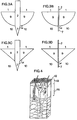
- Fig. 3 is a section of four different embodiments of the electrode tip portion and the stop means according to the invention; and
- Fig. 4 is a section in perspective of a skin portion.
- As appears from Fig. 1, an
electrode plate 1 is provided withseveral electrodes 2 fixed in theplate 1 and extending therethrough. Eachelectrode 2 is connected to acontrol unit 4 by anelectric line 3. Thecontrol unit 4 is in turn connected, by anelectric line 5, to acollector electrode 6 of opposite electrical polarity to theelectrodes 2. Theelectrode plate 1 with theelectrodes 2 projecting from its underside, and thecollector electrode 6 are applied to askin portion 10 during the stimulation operation. - Preferably, the
electrode plate 1 is shapable and substantially flat. The plate may be of different size, depending on the size of the skin portion to be stimulated. Further, the plate is made of some conventional pliable material enabling it to be used on curved parts of the body, such as the elbows, the shoulders and the knees. The plate may be about 1-500 cm2, but preferably is about 4-300 cm2. - Naturally, the size of the plate depends on the skin area to be stimulated. Where the skin has low receptor density, fairly large areas have to be stimulated. For instance, comparatively large areas are stimulated on the back and the back of the head, while smaller areas are stimulated on the arms and the face. If need be, one or
more electrode plates 1 may in addition be connected when large areas of the skin are to be stimulated. Electrically, theelectrode plate 1 may be an insulator in its entirety or it may be made up of an insulator in the layer closest to the skin and, in an overlying layer, consist either of electrically conductive wires from theelectrodes 2 to thecontrol unit 4 or of printed board. In a preferred embodiment, theelectrode plate 1 is a sleeve of silicon rubber. -
Electrodes 2 extend through recesses in theelectrode plate 1 and project from the underside of the plate facing theskin portion 10, as shown in Fig. 2. Theelectrodes 2 are substantially elongate and are made of conventional conductive material. By anelectric line 3, the upper end of eachelectrode 2 is connected to thecontrol unit 4. This upper end may project from the upper side of theelectrode plate 1 facing away from the skin portion or it may be embedded in theelectrode plate 1. At the lower end, theelectrode 2 ends in anelectrode tip portion 7 intended to penetrate theskin portion 10. It is of considerable importance that theelectrode tip portion 7 is so designed that it can penetrate the skin sufficiently to achieve the desired stimulation of the skin receptors. Theelectrode tip portion 7 is pointed at an angle less than 90°, preferably less than 45°. Theelectrode tip portion 7 may be perfectly conically pointed or convexly/concavely conically pointed or it may have a cutting edge. It may also be otherwise designed, provided that it meets the requirements at issue, and thus may have the shape of a needle or a pin. The cross-sectional surface of theelectrode tip portion 7 can also be so small that the skin is penetrated under the exertion of a pressure, regardless of its design. The cross-sectional surface should be about 1 mm2 at the most, preferably 0.25 mm2 at the most, in order to minimise skin injuries caused by the penetration. - To achieve controlled penetration, a stop means 9 is furthermore provided round the projecting lower electrode part formed with the
electrode tip portion 7, in such a manner that it also surrounds theelectrode 2 and serves as a spacer between the underside of theelectrode plate 1 and theskin portion 10. This also creates anair gap 11 between theelectrode plate 1 and theskin portion 10. The term "electrode tip portion" is used to designate the portion of theelectrode 2 projecting from the stop means 9. The stop means 9 can be made of any conventional material, e.g. either an electrically conductive material or an insulating material, and have any suitable design. Preferably, the stop means is a hollow cylinder with a height of about 0.1-5 mm. Its skin contact surface, which preferably is annular, has a size of about 0.2-25 mm2, depending on the electrode density and the curvature of the skin surface. In a preferred embodiment, the skin contact surface of the stop means 9 is about 3 mm2. The stop means 9 may be a separate component of the device, but it may also be made in one piece with theelectrodes 2. Thus, the stop means 9 enables theelectrode 2 to penetrate to a predetermined depth in the skin when pressure is applied from above. Preferably, the lower end of the stop means 9 is convex for optimal skin contact. The skin contact surface may alternatively be flat, be flat closest to theelectrode tip portion 7 and rounded up towards theelectrode plate 1, or be conical. As appears from Figs 3A-D, showing alternative embodiments of the invention, the angle α between the stop means 9 and theelectrode tip portion 7 should not exceed 160° to enable satisfactory control of the penetration depth of theelectrode 2 into the skin. In the preferred embodiment, the angle α between the stop means 9 and theelectrode tip portion 7 is about 90°. Basically, a device in which theelectrode plate 1 in itself serves as stop means is also conceivable. However, such an arrangement does not enable satisfactory control of the penetration depth of theelectrodes 2 into the skin. - Since different receptors are located at different depths in the skin, it is possible to select the group of receptors to be stimulated by varying the penetration depth of the
electrode tip portion 7 into the skin. The present invention is preferably used for stimulating receptors in the lower part of the epidermis and the upper part of the dermis. When theelectrode 2 is applied to theskin portion 10 under the exertion of a pressure, theelectrode tip portion 7 perforates the electrically insulating layers of the epidermis (stratum corneum and stratum lucidum, i.e. the horny layer made up of dead cells of the skin). As appears from Fig. 4, which is a section illustrating the structures and the positions of receptors in the skin, theelectrodes 2 should reach down to the lower part of the epidermis 13 and the upper part of thedermis 16, being the location of bothnociceptors 14 andsensitive mechanoreceptors 15. The term "receptors" used throughout this description relates to mechanoreceptors and nociceptors as well as their intracutaneous nerve fibres in the layers of theskin 13 and 16. Thehorny layer 12 constitutes the uppermost part of the epidermis 13. When theelectrode tip portion 7 passes these layers of the skin, the electrical resistance between the electrode tip and the receptor is considerably reduced. The voltage and the current intensity required for activating receptors in the skin may therefore be considerably reduced as well. The skin penetration depth, i.e. the vertical distance between thetip 8 of theelectrode tip portion 7 and an imaginary extension of the surface of the stop means 9 applied against theskin portion 10, depends on the type of skin to be stimulated and on how far into the skin stimulation is to take place. Theelectrode tip portion 7 preferably projects about 0.1-2.0 mm, in a particularly preferred embodiment about 0.2-1.2 mm. The term "skin penetration", used throughout the description and the claims, encompasses penetration through the skin layers to thesensitive mechanoreceptors 15 and thenociceptors 14 found in the lower part of the epidermis 13 and the upper part of thedermis 16. - The
electrodes 2 can be arranged at different distances from theelectrode plate 1. For practical reasons, however, distances above about 30-50 mm and below about 2-5 mm should not be used. The number ofelectrodes 2 perelectrode plate 1 may vary between about 2 and 100, and preferably is about 15-50. Theelectrodes 2 can be asymmetrically arranged on theelectrode plate 1, depending on the skin portion to be treated. The above parameters are easily determined by anyone skilled in the art. - In a preferred embodiment of the invention, the plate is oval or rectangular and has a surface area of about 100 cm2, 16 electrodes being symmetrically arranged on the plate and spaced apart 20 mm. In the preferred embodiment, the
electrodes 2 are in addition cylindrical and have a diameter of about 0.5 mm. - In the preferred embodiment, the
electrode plate 1 consists of an upper layer having integrated lines/printed boards and a lower insulator layer. The stop means 9 is made in one piece with theelectrodes 2. - The
control unit 4, which is connected to eachelectrode 2 on theelectrode plate 1 byelectric lines 3, utilises conventional electronics and is designed to provide the required values of the electronic parameters used in the invention. Thecontrol unit 4 may be either enclosed in a separate container or encased directly on theelectrode plate 1. In the preferred embodiment of the invention, the electrodes are activated consecutively, i.e. in turn, to achieve optimal effect. Although simultaneous stimulation of all the electrodes is possible, this does not yield as good results. With the aid of thecontrol unit 4, the frequency for eachelectrode 2 can be varied between about 1 Hz and 300 Hz, preferably between about 5 Hz and 100 Hz, but is about 40 Hz in a preferred embodiment. The voltage and the current intensity required for activating the receptors in the skin can, according to the invention, be reduced to about 40 V and about 6 mA, at the most, preferably to about 20 V and about 3 mA, at the most. In the preferred embodiment, the voltage does not exceed about 15 V and the current intensity does not exceed about 1-3 mA. When using the inventive device for pain and itch relief, the voltage is gradually increased during a first period lasting about 5-10 min, which considerably reduces any feeling of discomfort as compared with the discomfort felt when the stimulation voltage is increased stepwise to the required level. Stimulation then continues for about 20-50 min, but more time may be needed for some states of pain. The required pulse duration is about 0.01-5 ms, preferably 0.2-1 ms, and is 0.2 ms in a preferred embodiment. The above parameters depend on which portion of the skin is to be stimulated. - By an
electric line 5, thecontrol unit 4 is connected to a shapable, electricallyconductive collector electrode 6, which is an electrode of opposite polarity to theelectrodes 2. Thecollector electrode 6 is made of conventional material and may, like theelectrode plate 1, be adjusted to curved body surfaces when need be. The shape and surface of thecollector electrode 6 can be varied to a considerable extent, and the surface area is about 15-25 cm2 in a preferred embodiment. When using the inventive device, the required current transfer takes place between theelectrodes 2 and thecollector electrode 6 of opposite polarity. Thecollector electrode 6 can be applied to theskin portion 10 at a distance from theelectrode plate 1 or be applied as a frame round the plate. Thecollector electrode 6 may also be otherwise positioned in relation to theelectrode plate 1. - Thus, the
electrodes 2 can be either cathodes or anodes. When theelectrodes 2 are cathodes, thecollector electrode 6 is an anode, and vice versa. In a preferred embodiment of the invention, theelectrodes 2 are cathodes and thecollector electrode 6 is an anode. - In another embodiment of the invention, the
electrodes 2 on theelectrode plate 1 can operate in pairs as cathode and anode. Alternatively, groups of two ormore electrodes 2 on theelectrode plate 1 can act as mutual cathode-anode pairs with another group ofelectrodes 2 on theelectrode plate 1. In this embodiment, thecollector electrode 6 is superfluous and thus dispensed with. - The inventive device can be applied to the
skin portion 10 at issue with the aid of a conventional fixing device (not shown), such as a sleeve with an adjustable clamping means, or with the aid of tissue adhesive. It is of great importance that theelectrode plate 1 with theelectrodes 2 and theirelectrode tip portions 7 can be applied against the skin portion at issue by adjustable pressure exertion to achieve the skin penetration required. - With the aid of the invention, it is thus possible to affect also the motor activity of disabled people whose muscles are partly or totally paralysed. Normally, the current intensity then is not gradually increased for 5-10 min. In such an instance, the skin area is stimulated in a manner coordinated with the intended motor activity.
- Furthermore, the flow-through of blood in underlying tissue can be locally increased by stimulation with the aid of the device according to the invention. Such an increase in the blood flow has been shown, inter alia by an increase in temperature in the treated area of the skin.
- In a test involving 6 patients, pronounced and local pain relief in the stimulation area occurred within 3-5 min. The pain caused by heat stimulation of the skin surface showed that the pain threshold had been considerably raised. As a rule, the feeling of pin pricking disappeared completely. Moreover, tests on 4 patients with back muscle pain and tennis elbow showed good and long-term pain relief lasting several days.
- In addition, the inventive device totally blocked itch, caused by an injection of histamine, in 3 patients and considerably relieved the itch in another 3 patients after about 5 min. of stimulation. The effect lasted more than 1 h.
Claims (9)
- A device for relieving chronic and acute states of pain as well as itch, for affecting the motor activity of disabled people, or for increasing the flow-through of blood in underlying tissue, said device comprising a shapable electrode plate (1) through which extend a plurality of electrodes (2) which are fixed in the electrode plate (1) and terminate, at their respective free ends, in electrode tip portions (7) for skin penetration, characterised in that(a) the electrode tip portion (7) of each electrode (2), at a distance of about 0.1-2.0 mm from the electrode tip (8), is surrounded by a stop means (9) separating the electrode plate (1) from the skin portion (10),(b) the electrodes (2) cooperate with a collector electrode (6) of opposite electrical polarity to the electrodes (2), and(c) the electrodes (2) and the collector electrode (6) are electrically connected to a control unit (4) designed to activate the electrodes (2) consecutively, so that when pressure is applied on the electrodes (2), the electrode tip portions (7) will penetrate the isolating outer layers of the epidermis to stimulate the receptors of the skin.
- A device as claimed in claim 1, characterised in that the electrodes (2) are cathodes, and that the collector electrode (6) is an anode.
- A device as claimed in any one of the preceding claims, characterised in that the control unit (4) is designed to activate the electrodes (2) consecutively at a frequency of about 1-300 Hz, a current intensity not exceeding about 6 mA, and a pulse duration of about 0.01-5 ms.
- A device as claimed in claim 3, characterised in that the control unit (4) is designed to activate the electrodes (2) consecutively at a frequency of preferably about 5-100 Hz, a current intensity not exceeding about 3mA, and a pulse duration of about 0.2-1.0 ms.
- A device as claimed in any one of the preceding claims, characterised in that the electrode plate (1) has a surface area of 4-300 cm2, and that 2-100 electrodes (2) are fixed in the electrode plate (1).
- A device as claimed in any one of the preceding claims, characterised in that the electrode tip portion (7) of each electrode (2) is pointed, has a cutting edge or so small a cross-sectional surface that the skin portion (10) is penetrated, regardless of the design of the electrode tip (8), and that the electrode tip portion (7) is surrounded by the stop means (9) at a distance of about 0.2-1.2 mm from the tip (8).
- A device as claimed in any one of the preceding claims, characterised in that the contact surface of the stop means (9) with the skin is flat, flat closest to the electrode tip portion (7) and rounded up towards the electrode plate (1), or conical, in which case the angle between the electrode tip portion (7) and the stop means (9) does not exceed 160°.
- A device as claimed in any one of the preceding claims, characterised in that one or more electrode plates (1) according to the invention are connected for stimulating a major skin portion.
- A device as claimed in any one of the preceding claims, characterised in that the electrodes (2) in the electrode plate (1), in pairs or groups, form mutual anode-cathode pairs, the collector electrode (6) being excluded from the device.
Applications Claiming Priority (3)
| Application Number | Priority Date | Filing Date | Title |
|---|---|---|---|
| SE9201453 | 1992-05-08 | ||
| SE9201453A SE9201453L (en) | 1992-05-08 | 1992-05-08 | MEDICAL DEVICE FOR RELIEFING THE PAIN CONDITION INCLUDING AN ELECTRIC PLATE |
| PCT/SE1993/000287 WO1993023112A1 (en) | 1992-05-08 | 1993-04-05 | Medical device |
Publications (2)
| Publication Number | Publication Date |
|---|---|
| EP0606412A1 EP0606412A1 (en) | 1994-07-20 |
| EP0606412B1 true EP0606412B1 (en) | 1996-08-14 |
Family
ID=20386188
Family Applications (1)
| Application Number | Title | Priority Date | Filing Date |
|---|---|---|---|
| EP93910490A Expired - Lifetime EP0606412B1 (en) | 1992-05-08 | 1993-04-05 | Medical device |
Country Status (10)
| Country | Link |
|---|---|
| US (1) | US5449378A (en) |
| EP (1) | EP0606412B1 (en) |
| AT (1) | ATE141177T1 (en) |
| AU (1) | AU4096193A (en) |
| CA (1) | CA2135301C (en) |
| DE (1) | DE69304035T2 (en) |
| ES (1) | ES2090999T3 (en) |
| PL (1) | PL171134B1 (en) |
| SE (1) | SE9201453L (en) |
| WO (1) | WO1993023112A1 (en) |
Families Citing this family (105)
| Publication number | Priority date | Publication date | Assignee | Title |
|---|---|---|---|---|
| US6024733A (en) | 1995-06-07 | 2000-02-15 | Arthrocare Corporation | System and method for epidermal tissue ablation |
| AUPM540394A0 (en) * | 1994-05-03 | 1994-05-26 | Hatziorfanos, Peter | Cellulite removal process |
| US6560480B1 (en) * | 1994-10-24 | 2003-05-06 | Transscan Medical Ltd. | Localization of anomalies in tissue and guidance of invasive tools based on impedance imaging |
| US6678552B2 (en) | 1994-10-24 | 2004-01-13 | Transscan Medical Ltd. | Tissue characterization based on impedance images and on impedance measurements |
| US5810742A (en) | 1994-10-24 | 1998-09-22 | Transcan Research & Development Co., Ltd. | Tissue characterization based on impedance images and on impedance measurements |
| US7758537B1 (en) | 1995-11-22 | 2010-07-20 | Arthrocare Corporation | Systems and methods for electrosurgical removal of the stratum corneum |
| US6896672B1 (en) | 1995-11-22 | 2005-05-24 | Arthrocare Corporation | Methods for electrosurgical incisions on external skin surfaces |
| US5861015A (en) * | 1997-05-05 | 1999-01-19 | Benja-Athon; Anuthep | Modulation of the nervous system for treatment of pain and related disorders |
| SE513814C2 (en) * | 1998-03-31 | 2000-11-06 | Aditus Medical Ab | Device for the treatment of diseases with electric fields |
| US6159163A (en) * | 1998-05-07 | 2000-12-12 | Cedars-Sinai Medical Center | System for attenuating pain during bone marrow aspiration and method |
| IL125990A (en) * | 1998-08-30 | 2004-12-15 | Moshe Ein-Gal | Electrocoagulation apparatus |
| ATE262881T1 (en) * | 1999-11-12 | 2004-04-15 | Josef Constantin Szeles | PUNCTUAL STIMULATION THERAPY DEVICE |
| US6549810B1 (en) | 1999-12-01 | 2003-04-15 | Vertis Neuroscience, Inc. | Percutaneous electrical therapy system with electrode depth control |
| US6549797B1 (en) | 1999-12-01 | 2003-04-15 | Vertis Neuroscience, Inc. | Electrode remover for a percutaneous electrical therapy system |
| US6516226B1 (en) | 1999-12-01 | 2003-02-04 | Vertis Neuroscience, Inc. | Percutaneous electrical therapy system for minimizing electrode insertion discomfort |
| US6522927B1 (en) | 1999-12-01 | 2003-02-18 | Vertis Neuroscience, Inc. | Electrode assembly for a percutaneous electrical therapy system |
| US6493592B1 (en) | 1999-12-01 | 2002-12-10 | Vertis Neuroscience, Inc. | Percutaneous electrical therapy system with electrode position maintenance |
| US6529776B1 (en) | 1999-12-01 | 2003-03-04 | Vertis Neuroscience, Inc. | Method and apparatus for repositioning a percutaneous probe |
| US6912424B2 (en) * | 1999-12-01 | 2005-06-28 | Meagan, Medical, Inc. | Apparatus and method for coupling therapeutic and/or monitoring equipment to a patient |
| US6560491B1 (en) | 1999-12-01 | 2003-05-06 | Vertis Neuroscience, Inc. | Percutaneous electrical therapy system providing electrode axial support |
| US6622051B1 (en) | 1999-12-01 | 2003-09-16 | Vertis Neuroscience, Inc. | Percutaneous electrical therapy system with electrode entry angle control |
| US6539264B1 (en) | 1999-12-01 | 2003-03-25 | Vertis Neuroscience, Inc. | Percutaneous electrical therapy system with sharp point protection |
| US6556869B1 (en) | 1999-12-01 | 2003-04-29 | Vertis Neuroscience, Inc. | Electrode introducer for a percutaneous electrical therapy system |
| US6904324B2 (en) * | 1999-12-01 | 2005-06-07 | Meagan Medical, Inc. | Method and apparatus for deploying a percutaneous probe |
| US20080033492A1 (en) * | 2000-01-07 | 2008-02-07 | Biowave Corporation | Electro-therapy method |
| US7013179B2 (en) * | 2000-01-07 | 2006-03-14 | Biowave Corporation | Percutaneous electrode array |
| US6564079B1 (en) | 2000-07-27 | 2003-05-13 | Ckm Diagnostics, Inc. | Electrode array and skin attachment system for noninvasive nerve location and imaging device |
| US7118555B2 (en) * | 2000-09-21 | 2006-10-10 | Meagan Medical, Inc. | Method and apparatus for repositioning a percutaneous probe |
| USD480478S1 (en) | 2000-09-28 | 2003-10-07 | Vertis Neuroscience, Inc. | Percutaneous probe applicator |
| US6671557B1 (en) | 2000-10-10 | 2003-12-30 | Meagan Medical, Inc. | System and method for providing percutaneous electrical therapy |
| AT5005U1 (en) * | 2000-11-21 | 2002-02-25 | Ernst Biegler Ges M B H | ELECTRODESY SYSTEM FOR ELECTRICAL PUNCTUAL STIMULATION THERAPY AND HANDLING TOOL THEREFOR |
| WO2003084397A2 (en) | 2002-04-04 | 2003-10-16 | Transscan Medical Ltd. | Breast cancer screening |
| US6785569B2 (en) | 2001-09-07 | 2004-08-31 | Orbital Research | Dry physiological recording electrode |
| US7286864B1 (en) | 2001-09-07 | 2007-10-23 | Orbital Research, Inc. | Dry physiological recording device |
| US9763590B1 (en) * | 2004-11-12 | 2017-09-19 | Orbital Research Inc. | Physiological recording device or electrode |
| US6782283B2 (en) | 2001-09-07 | 2004-08-24 | Robert N. Schmidt | Dry penetrating recording device |
| USD475463S1 (en) | 2001-09-28 | 2003-06-03 | Vertis Neuroscience, Inc. | Control device for delivering electrical therapy |
| US6920883B2 (en) | 2001-11-08 | 2005-07-26 | Arthrocare Corporation | Methods and apparatus for skin treatment |
| JP2005537069A (en) * | 2002-08-30 | 2005-12-08 | インターナショナル リハビリテイティブ サイエンシズ インコーポレーティッド | Integrated deep percutaneous / surface electrical stimulation |
| US20110071439A1 (en) * | 2003-10-22 | 2011-03-24 | Wicab, Inc. | Tactile input system |
| US20050149145A1 (en) * | 2003-12-29 | 2005-07-07 | Coulter George G. | Enhanced device for diminishing or eliminating the pain caused by superficial therapeutic injection or superficial body tissue sampling or the pain from a superficial injury as well as for the reduction of hemorrhage from an injured area |
| US8086318B2 (en) * | 2004-02-12 | 2011-12-27 | Ndi Medical, Llc | Portable assemblies, systems, and methods for providing functional or therapeutic neurostimulation |
| US7120499B2 (en) * | 2004-02-12 | 2006-10-10 | Ndi Medical, Llc | Portable percutaneous assemblies, systems and methods for providing highly selective functional or therapeutic neuromuscular stimulation |
| US8467875B2 (en) | 2004-02-12 | 2013-06-18 | Medtronic, Inc. | Stimulation of dorsal genital nerves to treat urologic dysfunctions |
| JP2007531562A (en) * | 2004-02-12 | 2007-11-08 | エヌディーアイ メディカル, エルエルシー | Portable assembly, system and method for providing functional or therapeutic neuromuscular stimulation |
| WO2005107848A2 (en) | 2004-04-01 | 2005-11-17 | The General Hospital Corporation | Method for dermatological treatment using chromophores |
| US8571648B2 (en) | 2004-05-07 | 2013-10-29 | Aesthera | Apparatus and method to apply substances to tissue |
| US8195304B2 (en) | 2004-06-10 | 2012-06-05 | Medtronic Urinary Solutions, Inc. | Implantable systems and methods for acquisition and processing of electrical signals |
| US9205255B2 (en) | 2004-06-10 | 2015-12-08 | Medtronic Urinary Solutions, Inc. | Implantable pulse generator systems and methods for providing functional and/or therapeutic stimulation of muscles and/or nerves and/or central nervous system tissue |
| US7761167B2 (en) | 2004-06-10 | 2010-07-20 | Medtronic Urinary Solutions, Inc. | Systems and methods for clinician control of stimulation systems |
| US8165692B2 (en) | 2004-06-10 | 2012-04-24 | Medtronic Urinary Solutions, Inc. | Implantable pulse generator power management |
| US7283867B2 (en) | 2004-06-10 | 2007-10-16 | Ndi Medical, Llc | Implantable system and methods for acquisition and processing of electrical signals from muscles and/or nerves and/or central nervous system tissue |
| US9308382B2 (en) | 2004-06-10 | 2016-04-12 | Medtronic Urinary Solutions, Inc. | Implantable pulse generator systems and methods for providing functional and/or therapeutic stimulation of muscles and/or nerves and/or central nervous system tissue |
| US20060047281A1 (en) | 2004-09-01 | 2006-03-02 | Syneron Medical Ltd. | Method and system for invasive skin treatment |
| US7463927B1 (en) | 2004-09-02 | 2008-12-09 | Intelligent Neurostimulation Microsystems, Llc | Self-adaptive system for the automatic detection of discomfort and the automatic generation of SCS therapies for chronic pain control |
| AU2005296341B2 (en) * | 2004-10-19 | 2011-06-30 | Meagan Medical, Inc. | Method and means for electrical stimulation of cutaneous sensory receptors |
| US8417352B2 (en) | 2004-10-19 | 2013-04-09 | Meagan Medical, Inc. | System and method for stimulating sensory nerves |
| NL1028232C2 (en) | 2005-02-09 | 2006-08-11 | Univ Twente | Equipment is for stimulation of sensitivity nerves in skin of person and comprises substrate on which extends matrix of electrodes connected on one hand to current source and on skin of person for transmission of electrical current |
| US20070142885A1 (en) * | 2005-11-29 | 2007-06-21 | Reliant Technologies, Inc. | Method and Apparatus for Micro-Needle Array Electrode Treatment of Tissue |
| US9610459B2 (en) | 2009-07-24 | 2017-04-04 | Emkinetics, Inc. | Cooling systems and methods for conductive coils |
| US20080306325A1 (en) | 2006-10-02 | 2008-12-11 | Emkinetics | Method and apparatus for magnetic induction therapy |
| US9339641B2 (en) | 2006-01-17 | 2016-05-17 | Emkinetics, Inc. | Method and apparatus for transdermal stimulation over the palmar and plantar surfaces |
| US9308363B2 (en) | 2006-02-21 | 2016-04-12 | Teodor Goroszeniuk | Neurostimulation for treating pain, improving function and other nervous system related conditions |
| US20070288078A1 (en) * | 2006-03-17 | 2007-12-13 | Steve Livneh | Apparatus and method for skin tightening and corrective forming |
| US9480846B2 (en) | 2006-05-17 | 2016-11-01 | Medtronic Urinary Solutions, Inc. | Systems and methods for patient control of stimulation systems |
| US11224742B2 (en) | 2006-10-02 | 2022-01-18 | Emkinetics, Inc. | Methods and devices for performing electrical stimulation to treat various conditions |
| US10786669B2 (en) | 2006-10-02 | 2020-09-29 | Emkinetics, Inc. | Method and apparatus for transdermal stimulation over the palmar and plantar surfaces |
| US9005102B2 (en) | 2006-10-02 | 2015-04-14 | Emkinetics, Inc. | Method and apparatus for electrical stimulation therapy |
| US8007493B2 (en) | 2006-10-16 | 2011-08-30 | Syneron Medical Ltd. | Methods and devices for treating tissue |
| US8142426B2 (en) | 2006-10-16 | 2012-03-27 | Syneron Medical Ltd. | Methods and devices for treating tissue |
| US8273080B2 (en) | 2006-10-16 | 2012-09-25 | Syneron Medical Ltd. | Methods and devices for treating tissue |
| US8133216B2 (en) | 2006-10-16 | 2012-03-13 | Syneron Medical Ltd. | Methods and devices for treating tissue |
| US9283029B2 (en) * | 2007-01-31 | 2016-03-15 | Alma Lasers Ltd. | Skin treatment using a multi-discharge applicator |
| EP2136872A4 (en) * | 2007-04-13 | 2010-05-12 | Alejandro Covalin | Apparatus and method for the treatment of headache |
| US9364287B2 (en) * | 2007-06-05 | 2016-06-14 | Reliant Technologies, Inc. | Method for reducing pain of dermatological treatments |
| US20090036958A1 (en) * | 2007-08-01 | 2009-02-05 | Primaeva Medical, Inc. | Methods and devices for treating tissue |
| US20120143178A9 (en) * | 2007-06-15 | 2012-06-07 | Primaeva Medical, Inc. | Devices and methods for percutaneous energy delivery |
| US20080312647A1 (en) * | 2007-06-15 | 2008-12-18 | Primaeva Medical, Inc. | Methods and devices for treating tissue |
| US8845630B2 (en) | 2007-06-15 | 2014-09-30 | Syneron Medical Ltd | Devices and methods for percutaneous energy delivery |
| US20090012434A1 (en) * | 2007-07-03 | 2009-01-08 | Anderson Robert S | Apparatus, method, and system to treat a volume of skin |
| US20090069795A1 (en) * | 2007-09-10 | 2009-03-12 | Anderson Robert S | Apparatus and method for selective treatment of tissue |
| US20090093864A1 (en) * | 2007-10-08 | 2009-04-09 | Anderson Robert S | Methods and devices for applying energy to tissue |
| US20090112205A1 (en) * | 2007-10-31 | 2009-04-30 | Primaeva Medical, Inc. | Cartridge electrode device |
| US20090156958A1 (en) * | 2007-12-12 | 2009-06-18 | Mehta Bankim H | Devices and methods for percutaneous energy delivery |
| JP5676445B2 (en) * | 2008-08-01 | 2015-02-25 | エヌディーアイ メディカル, エルエルシー | Portable assembly, system and method for providing functional or therapeutic neural stimulation |
| US8882758B2 (en) * | 2009-01-09 | 2014-11-11 | Solta Medical, Inc. | Tissue treatment apparatus and systems with pain mitigation and methods for mitigating pain during tissue treatments |
| US8506506B2 (en) * | 2009-01-12 | 2013-08-13 | Solta Medical, Inc. | Tissue treatment apparatus with functional mechanical stimulation and methods for reducing pain during tissue treatments |
| US9278230B2 (en) | 2009-02-25 | 2016-03-08 | Syneron Medical Ltd | Electrical skin rejuvenation |
| US8788060B2 (en) * | 2009-07-16 | 2014-07-22 | Solta Medical, Inc. | Tissue treatment systems with high powered functional electrical stimulation and methods for reducing pain during tissue treatments |
| EP2456519A1 (en) * | 2009-07-23 | 2012-05-30 | Emkinetics, Inc. | Method and apparatus for magnetic induction therapy |
| EP2493551A4 (en) | 2009-10-26 | 2013-04-17 | Emkinetics Inc | Method and apparatus for electromagnetic stimulation of nerve, muscle, and body tissues |
| US20110202048A1 (en) * | 2010-02-12 | 2011-08-18 | Solta Medical, Inc. | Methods for pain reduction with functional thermal stimulation and tissue treatment systems |
| US8588884B2 (en) | 2010-05-28 | 2013-11-19 | Emkinetics, Inc. | Microneedle electrode |
| WO2012046231A2 (en) * | 2010-10-04 | 2012-04-12 | Nervomatrix Ltd. | Electrode for finding points of low impedance and applying electrical stimulation thereto |
| CA2881161C (en) | 2011-08-11 | 2020-06-30 | James R. Robertson | Symptom-treatment system |
| US9962546B2 (en) | 2013-02-21 | 2018-05-08 | Meagan Medical, Inc. | Cutaneous field stimulation with disposable and rechargeable components |
| US9192313B1 (en) * | 2013-03-14 | 2015-11-24 | Orbital Research Inc. | Dry physiological recording device and method of manufacturing |
| US10052257B2 (en) | 2013-06-13 | 2018-08-21 | Dyansys, Inc. | Method and apparatus for stimulative electrotherapy |
| US10130275B2 (en) | 2013-06-13 | 2018-11-20 | Dyansys, Inc. | Method and apparatus for autonomic nervous system sensitivity-point testing |
| WO2015176778A1 (en) * | 2014-05-23 | 2015-11-26 | Albrecht Molsberger | Therapeutically applicable multichannel direct current delivery device |
| MX364500B (en) * | 2014-10-31 | 2019-04-29 | Avent Inc | Non-invasive nerve stimulation system. |
| US10959674B2 (en) | 2017-10-23 | 2021-03-30 | Datafeel Inc. | Communication devices, methods, and systems |
| KR20240083855A (en) | 2020-10-30 | 2024-06-12 | 데이터필 인코포레이티드 | Wearable data communication devices, kits, methods, and systems |
| WO2022221203A1 (en) * | 2021-04-13 | 2022-10-20 | Pulse Biosciences, Inc. | Conductive spacer in an electrode assembly of an electrical treatment apparatus |
| EP4257175A1 (en) * | 2022-04-04 | 2023-10-11 | Aurimod GmbH | Electrode array and electrode for peripheral nerve stimulation |
Family Cites Families (26)
| Publication number | Priority date | Publication date | Assignee | Title |
|---|---|---|---|---|
| US3612061A (en) * | 1969-02-20 | 1971-10-12 | Inst Of Medical Sciences The | Flexible cutaneous electrode matrix |
| DE2555281C2 (en) * | 1975-12-09 | 1984-11-15 | Heinz Dipl.-Phys. 7800 Freiburg Dehnert | Electrode arrangement for tapping bioelectric body potentials |
| JPS5382980A (en) * | 1976-12-28 | 1978-07-21 | Agency Of Ind Science & Technol | Distribution type information transmission unit by multi point electric stimulas |
| US4453548A (en) * | 1981-06-08 | 1984-06-12 | Empi, Inc. | Method of improving sensory tolerance with modulated nerve stimulator |
| US4509535A (en) * | 1982-06-07 | 1985-04-09 | Horace Bryan | Electrode apparatus |
| DE3236756A1 (en) * | 1982-10-05 | 1984-04-05 | Physiomed - Medizintechnik GmbH, 8563 Schnaittach | Stimulating current therapy unit |
| IL75048A0 (en) * | 1984-05-04 | 1985-08-30 | Dervieux Dominique | Bipolar electrodes and apparatus comprising them for the relief of pains |
| DE3502913C1 (en) * | 1985-01-29 | 1986-07-03 | Günter Prof. Dr.rer.nat. 5100 Aachen Rau | Sensor for non-invasive detection of electrophysiological values |
| US4722354A (en) * | 1985-06-14 | 1988-02-02 | Jens Axelgaard | Electrical stimulation electrode |
| US4708149A (en) * | 1985-06-14 | 1987-11-24 | Jens Axelgaard | Electrical stimulation electrode |
| US4867166A (en) * | 1985-06-14 | 1989-09-19 | Jens Axelgaard | Electrical stimulation electrode |
| FR2599979B1 (en) * | 1986-06-11 | 1991-05-03 | Saeat Fluvita Sarl | FLEXIBLE ELECTRODES FOR HIGH FREQUENCY CURRENT APPLICATIONS |
| US4837049A (en) * | 1986-06-17 | 1989-06-06 | Alfred E. Mann Foundation For Scientific Research | Method of making an electrode array |
| EP0268701A1 (en) * | 1986-11-26 | 1988-06-01 | JAMUTRON GERÄTEBAU GmbH | Electric stimulator for medical and cosmetic applications |
| JPH05173Y2 (en) * | 1987-01-20 | 1993-01-06 | ||
| US4926879A (en) * | 1988-06-13 | 1990-05-22 | Sevrain-Tech, Inc. | Electro-tactile stimulator |
| US5178161A (en) * | 1988-09-02 | 1993-01-12 | The Board Of Trustees Of The Leland Stanford Junior University | Microelectronic interface |
| AU4634089A (en) * | 1988-11-21 | 1990-06-12 | Josef Constantin Szeles | Needle and therapeutic device for stimulating specific points of the body |
| EP0377057A1 (en) * | 1988-12-30 | 1990-07-11 | Leandro Bernardini | Hand-operated electromedical device for analgesic skin treatments |
| US4982742A (en) * | 1989-02-22 | 1991-01-08 | C&Y Technology, Inc. | Apparatus and method to facilitate healing of soft tissue wounds |
| CS275292B2 (en) * | 1989-02-22 | 1992-02-19 | Cvut Fakulta Elektrotechnick | Private rehabilitation apparatus with ion transcutaneous acceleration |
| US5067495A (en) * | 1989-09-27 | 1991-11-26 | Brehm Richard L | Electro wave therapy |
| GB8924559D0 (en) * | 1989-11-01 | 1989-12-20 | Capel Ifor D | Method for transcranial electrotherapy |
| DE4000893A1 (en) * | 1990-01-15 | 1991-07-18 | Bosch Gmbh Robert | Multichannel appts. for electro-simulation - provides several current circuits for patient with electrodes applying pulse signals |
| US4982743A (en) * | 1990-03-23 | 1991-01-08 | Pierson Marlin R | Itch reducer |
| US5133354A (en) * | 1990-11-08 | 1992-07-28 | Medtronic, Inc. | Method and apparatus for improving muscle tone |
-
1992
- 1992-05-08 SE SE9201453A patent/SE9201453L/en not_active IP Right Cessation
-
1993
- 1993-04-05 WO PCT/SE1993/000287 patent/WO1993023112A1/en not_active Ceased
- 1993-04-05 DE DE69304035T patent/DE69304035T2/en not_active Expired - Lifetime
- 1993-04-05 EP EP93910490A patent/EP0606412B1/en not_active Expired - Lifetime
- 1993-04-05 PL PL93305982A patent/PL171134B1/en unknown
- 1993-04-05 AU AU40961/93A patent/AU4096193A/en not_active Abandoned
- 1993-04-05 ES ES93910490T patent/ES2090999T3/en not_active Expired - Lifetime
- 1993-04-05 US US08/170,338 patent/US5449378A/en not_active Expired - Lifetime
- 1993-04-05 AT AT93910490T patent/ATE141177T1/en active
- 1993-04-05 CA CA002135301A patent/CA2135301C/en not_active Expired - Lifetime
Also Published As
| Publication number | Publication date |
|---|---|
| AU4096193A (en) | 1993-12-13 |
| CA2135301A1 (en) | 1993-11-25 |
| SE469465B (en) | 1993-07-12 |
| DE69304035T2 (en) | 1996-12-19 |
| DE69304035D1 (en) | 1996-09-19 |
| SE9201453D0 (en) | 1992-05-08 |
| US5449378A (en) | 1995-09-12 |
| SE9201453L (en) | 1993-07-12 |
| CA2135301C (en) | 2003-03-11 |
| ATE141177T1 (en) | 1996-08-15 |
| PL171134B1 (en) | 1997-03-28 |
| WO1993023112A1 (en) | 1993-11-25 |
| EP0606412A1 (en) | 1994-07-20 |
| ES2090999T3 (en) | 1996-10-16 |
Similar Documents
| Publication | Publication Date | Title |
|---|---|---|
| US5449378A (en) | Method and apparatus for the electric stimulation of skin receptors | |
| US20240216678A1 (en) | Systems and methods for tissue treatment | |
| EP0461151B1 (en) | Electro-therapy apparatus | |
| US9981120B2 (en) | Electrode set and stimulating device | |
| US5070862A (en) | Glove for electro-massage therapy | |
| CA2584722C (en) | Method and means for electrical stimulation of cutaneous sensory receptors | |
| US6038485A (en) | Current-controlling electrode | |
| US9308363B2 (en) | Neurostimulation for treating pain, improving function and other nervous system related conditions | |
| US20090048642A1 (en) | Neurostimulation | |
| US6078842A (en) | Electrode and iontophoretic device and method | |
| EP2830704B1 (en) | Apparatus for stimulating muscles of a subject | |
| US7200444B2 (en) | Method and device for electro-acupuncture | |
| KR102131691B1 (en) | Needle and Medical Handpiece including tha same | |
| Pomeranz | Electroacupuncture and transcutaneous electrical nerve stimulation | |
| WO2007096600A1 (en) | Improvements in and relating to neurostimulation | |
| Berlant | Method of determining optimal stimulation sites for transcutaneous electrical nerve stimulation | |
| Sherwood et al. | Biomedical engineering specifications for epidural spinal cord stimulation to augment motor performance | |
| RU40896U1 (en) | ELECTRODE DEVICE | |
| KR20080051495A (en) | Herbal Insulation Needle | |
| Stux et al. | 7 Electroacupuncture and Transcutaneous Electrical Nerve Stimulation | |
| Jenkner | Transdermal Stimulation | |
| WO2008015405A1 (en) | An electrical stimulator |
Legal Events
| Date | Code | Title | Description |
|---|---|---|---|
| PUAI | Public reference made under article 153(3) epc to a published international application that has entered the european phase |
Free format text: ORIGINAL CODE: 0009012 |
|
| 17P | Request for examination filed |
Effective date: 19931231 |
|
| AK | Designated contracting states |
Kind code of ref document: A1 Designated state(s): AT BE CH DE DK ES FR GB GR IE IT LI LU MC NL PT SE |
|
| GRAG | Despatch of communication of intention to grant |
Free format text: ORIGINAL CODE: EPIDOS AGRA |
|
| 17Q | First examination report despatched |
Effective date: 19951213 |
|
| GRAH | Despatch of communication of intention to grant a patent |
Free format text: ORIGINAL CODE: EPIDOS IGRA |
|
| GRAH | Despatch of communication of intention to grant a patent |
Free format text: ORIGINAL CODE: EPIDOS IGRA |
|
| GRAA | (expected) grant |
Free format text: ORIGINAL CODE: 0009210 |
|
| AK | Designated contracting states |
Kind code of ref document: B1 Designated state(s): AT BE CH DE DK ES FR GB GR IE IT LI LU MC NL PT SE |
|
| PG25 | Lapsed in a contracting state [announced via postgrant information from national office to epo] |
Ref country code: NL Free format text: LAPSE BECAUSE OF FAILURE TO SUBMIT A TRANSLATION OF THE DESCRIPTION OR TO PAY THE FEE WITHIN THE PRESCRIBED TIME-LIMIT Effective date: 19960814 Ref country code: LI Effective date: 19960814 Ref country code: GR Free format text: LAPSE BECAUSE OF FAILURE TO SUBMIT A TRANSLATION OF THE DESCRIPTION OR TO PAY THE FEE WITHIN THE PRESCRIBED TIME-LIMIT Effective date: 19960814 Ref country code: DK Effective date: 19960814 Ref country code: CH Effective date: 19960814 Ref country code: BE Effective date: 19960814 Ref country code: AT Effective date: 19960814 |
|
| REF | Corresponds to: |
Ref document number: 141177 Country of ref document: AT Date of ref document: 19960815 Kind code of ref document: T |
|
| ITF | It: translation for a ep patent filed | ||
| REG | Reference to a national code |
Ref country code: IE Ref legal event code: FG4D Free format text: 69431 |
|
| REF | Corresponds to: |
Ref document number: 69304035 Country of ref document: DE Date of ref document: 19960919 |
|
| ET | Fr: translation filed | ||
| REG | Reference to a national code |
Ref country code: ES Ref legal event code: FG2A Ref document number: 2090999 Country of ref document: ES Kind code of ref document: T3 |
|
| PG25 | Lapsed in a contracting state [announced via postgrant information from national office to epo] |
Ref country code: SE Effective date: 19961114 Ref country code: PT Effective date: 19961114 |
|
| REG | Reference to a national code |
Ref country code: ES Ref legal event code: FG2A Ref document number: 2090999 Country of ref document: ES Kind code of ref document: T3 |
|
| NLV1 | Nl: lapsed or annulled due to failure to fulfill the requirements of art. 29p and 29m of the patents act | ||
| REG | Reference to a national code |
Ref country code: CH Ref legal event code: PL |
|
| PG25 | Lapsed in a contracting state [announced via postgrant information from national office to epo] |
Ref country code: IE Free format text: LAPSE BECAUSE OF NON-PAYMENT OF DUE FEES Effective date: 19970405 |
|
| PG25 | Lapsed in a contracting state [announced via postgrant information from national office to epo] |
Ref country code: LU Free format text: LAPSE BECAUSE OF NON-PAYMENT OF DUE FEES Effective date: 19970430 |
|
| PLBE | No opposition filed within time limit |
Free format text: ORIGINAL CODE: 0009261 |
|
| STAA | Information on the status of an ep patent application or granted ep patent |
Free format text: STATUS: NO OPPOSITION FILED WITHIN TIME LIMIT |
|
| 26N | No opposition filed | ||
| PG25 | Lapsed in a contracting state [announced via postgrant information from national office to epo] |
Ref country code: MC Effective date: 19971031 |
|
| REG | Reference to a national code |
Ref country code: GB Ref legal event code: 732E |
|
| REG | Reference to a national code |
Ref country code: FR Ref legal event code: TP |
|
| REG | Reference to a national code |
Ref country code: ES Ref legal event code: PC2A |
|
| REG | Reference to a national code |
Ref country code: GB Ref legal event code: IF02 |
|
| REG | Reference to a national code |
Ref country code: FR Ref legal event code: TP Owner name: INTERNATIONAL REHABILITATIVE SCIENCES INC., DB, US Effective date: 20110920 |
|
| PGFP | Annual fee paid to national office [announced via postgrant information from national office to epo] |
Ref country code: GB Payment date: 20120327 Year of fee payment: 20 |
|
| PGFP | Annual fee paid to national office [announced via postgrant information from national office to epo] |
Ref country code: DE Payment date: 20120430 Year of fee payment: 20 |
|
| PGFP | Annual fee paid to national office [announced via postgrant information from national office to epo] |
Ref country code: FR Payment date: 20120503 Year of fee payment: 20 |
|
| PGFP | Annual fee paid to national office [announced via postgrant information from national office to epo] |
Ref country code: IT Payment date: 20120418 Year of fee payment: 20 |
|
| PGFP | Annual fee paid to national office [announced via postgrant information from national office to epo] |
Ref country code: ES Payment date: 20120426 Year of fee payment: 20 |
|
| REG | Reference to a national code |
Ref country code: DE Ref legal event code: R071 Ref document number: 69304035 Country of ref document: DE |
|
| REG | Reference to a national code |
Ref country code: GB Ref legal event code: PE20 Expiry date: 20130404 |
|
| REG | Reference to a national code |
Ref country code: ES Ref legal event code: FD2A Effective date: 20130711 |
|
| PG25 | Lapsed in a contracting state [announced via postgrant information from national office to epo] |
Ref country code: GB Free format text: LAPSE BECAUSE OF EXPIRATION OF PROTECTION Effective date: 20130404 Ref country code: ES Free format text: LAPSE BECAUSE OF EXPIRATION OF PROTECTION Effective date: 20130406 Ref country code: DE Free format text: LAPSE BECAUSE OF EXPIRATION OF PROTECTION Effective date: 20130406 |