EP0606000B1 - Electric razor - Google Patents
Electric razor Download PDFInfo
- Publication number
- EP0606000B1 EP0606000B1 EP93310390A EP93310390A EP0606000B1 EP 0606000 B1 EP0606000 B1 EP 0606000B1 EP 93310390 A EP93310390 A EP 93310390A EP 93310390 A EP93310390 A EP 93310390A EP 0606000 B1 EP0606000 B1 EP 0606000B1
- Authority
- EP
- European Patent Office
- Prior art keywords
- shaving
- fan
- cutter
- cutters
- drive shaft
- Prior art date
- Legal status (The legal status is an assumption and is not a legal conclusion. Google has not performed a legal analysis and makes no representation as to the accuracy of the status listed.)
- Expired - Lifetime
Links
- 230000000712 assembly Effects 0.000 claims description 16
- 238000000429 assembly Methods 0.000 claims description 16
- 238000003825 pressing Methods 0.000 claims description 3
- 230000003670 easy-to-clean Effects 0.000 abstract 1
- 230000005540 biological transmission Effects 0.000 description 13
- 238000004140 cleaning Methods 0.000 description 3
- 230000000149 penetrating effect Effects 0.000 description 2
- 206010044625 Trichorrhexis Diseases 0.000 description 1
- 210000000078 claw Anatomy 0.000 description 1
- 238000001816 cooling Methods 0.000 description 1
- 230000000694 effects Effects 0.000 description 1
- 230000001815 facial effect Effects 0.000 description 1
- 239000004519 grease Substances 0.000 description 1
- 238000003780 insertion Methods 0.000 description 1
- 230000037431 insertion Effects 0.000 description 1
- 239000000463 material Substances 0.000 description 1
- 239000002184 metal Substances 0.000 description 1
- 238000000034 method Methods 0.000 description 1
- 239000000203 mixture Substances 0.000 description 1
- 238000012986 modification Methods 0.000 description 1
- 230000004048 modification Effects 0.000 description 1
- 230000001012 protector Effects 0.000 description 1
- 238000010008 shearing Methods 0.000 description 1
- 229920003002 synthetic resin Polymers 0.000 description 1
- 239000000057 synthetic resin Substances 0.000 description 1
Images


Classifications
-
- B—PERFORMING OPERATIONS; TRANSPORTING
- B26—HAND CUTTING TOOLS; CUTTING; SEVERING
- B26B—HAND-HELD CUTTING TOOLS NOT OTHERWISE PROVIDED FOR
- B26B19/00—Clippers or shavers operating with a plurality of cutting edges, e.g. hair clippers, dry shavers
- B26B19/14—Clippers or shavers operating with a plurality of cutting edges, e.g. hair clippers, dry shavers of the rotary-cutter type; Cutting heads therefor; Cutters therefor
- B26B19/141—Details of inner cutters having their axes of rotation perpendicular to the cutting surface
-
- B—PERFORMING OPERATIONS; TRANSPORTING
- B26—HAND CUTTING TOOLS; CUTTING; SEVERING
- B26B—HAND-HELD CUTTING TOOLS NOT OTHERWISE PROVIDED FOR
- B26B19/00—Clippers or shavers operating with a plurality of cutting edges, e.g. hair clippers, dry shavers
- B26B19/14—Clippers or shavers operating with a plurality of cutting edges, e.g. hair clippers, dry shavers of the rotary-cutter type; Cutting heads therefor; Cutters therefor
-
- B—PERFORMING OPERATIONS; TRANSPORTING
- B26—HAND CUTTING TOOLS; CUTTING; SEVERING
- B26B—HAND-HELD CUTTING TOOLS NOT OTHERWISE PROVIDED FOR
- B26B19/00—Clippers or shavers operating with a plurality of cutting edges, e.g. hair clippers, dry shavers
- B26B19/38—Details of, or accessories for, hair clippers, or dry shavers, e.g. housings, casings, grips, guards
- B26B19/44—Suction means for collecting severed hairs or for the skin to be shaved
Definitions
- the present invention relates to an electric razor and more particularly to an electric rotary razor.
- the inner cutters are rotated under the outer cutters, and the whiskers are cut by the shearing force provided by the outer and inner cutters.
- One such electric razor has a single shaving unit that consists of a single inner cutter and a single outer cutter installed in a head frame of the razor.
- Another such electric razor has three shaving units arranged in an equilateral triangular configuration on a head frame.
- US-A-4089110 discloses a shaver in which a fan wheel is disposed in a compartment provided between an encased gear assembly and a motor housing.
- the fan wheel which is of such a size as the compartment permits, is mounted to the shaft of the motor.
- the fan wheel draws in air through protector grills of the shaver heads to effect cooling of the grills for a more comfortable shave and both draws skin to the grills and whiskers into the grills for a closer and a more uniformally clean shave.
- FR-A-1103679 discloses an electric razor which includes a plurality of fans installed coaxially with the inner cutters of the shaving units.
- a primary aim of the present invention is to provide an electric razor that can collect the shaving debris in a receptacle provided under the shaving units so that the shaving debris is kept away from the shaving units so as not to adhere thereto, thus keeping the shaving units clean.
- the present invention provides an electric razor comprising: a head frame installed in a freely detachable manner over a drive shaft holder, said drive shaft holder being receptacle shaped for collecting shaving debris, so that said head frame covers said drive shaft holder; shaving units installed on a back side of said head frame, each of said shaving units consisting of an outer cutter with slits for introducing whiskers and an inner cutter which in use rotates on a back surface of said outer cutter to shear whiskers introduced through said slits, each inner cutter having cutting blades which slide on a back surface of a corresponding outer cutter, said cutting blades being formed at ends of a plurality of arms which are extended upwardly from a central part of said inner cutter and being inclined in a direction of rotation; drive shafts projecting from said drive shaft holder which are coupled to said inner cutters and connected to a driving source; and a fan assembly including a plurality of fan blades which in use is rotated together with said inner cutters by a driving force for said drive shafts;
- each fan assembly is made up of a cylindrical base block, an engagement hole formed in the bottom of the base block, at least one fan blade provided on the circumferential surface of the cylindrical base block to extend in the radial direction, and an engagement projection provided on the top surface of the base block.
- Each fan assembly is installed between an inner cutter and the drive shaft that rotates together with that inner cutter.
- the fan blades extend substantially in the axial direction of the base block so that the upper edges are located immediately beneath the back surface of the outer cutter.
- the electric razor may include supporting tubes for supporting the outer cutters by pressing them from inside the razor.
- the inner cutters and the fan assemblies are positioned inside respective supporting tubes.
- the whiskers penetrating the outer cutters through the slits thereof are sheared by the outer cutters and inner cutters, and these sheared whiskers are blown downward (as if being sucked in) by the fan blades which rotate together with the inner cutters.
- the sheared whiskers are collected in the drive shaft holder which is a cylindrical receptacle shape.
- Each inner cutter and fan assembly is provided inside a respective supporting tube which supports the outer cutter. Accordingly, the supporting tubes act as guides for the whiskers dropping into the drive shaft holder without being scattered.
- reference numeral 12 is the housing of an electric razor 10.
- the housing 12 has an opening 12a at the upper end, and a fixing frame 14 is inserted into the housing 12 through this opening 12a and fixed inside the housing 12.
- a motor 16 is mounted to the undersurface of the fixing frame 14.
- the axle 16a of the motor 16 protrudes through a hole 14a of the fixing frame 14, and a drive gear 18 is coupled to the motor axle 16a.
- Three transmission gears 20 are rotatably provided on the fixing frame 14 and engaged with the drive gear 18. These transmission gears 20 are arranged in an equilateral triangle configuration, and drive shafts 24 (only one is shown) are engaged with the transmission gears 20. Since all three transmission gears 20 have the same structure, only one transmission gear 20 and its related elements will be described below.
- the transmission gear 20 includes a shaft tube 20a which is rotatable on a shaft 22 that is fixed to the fixing frame 14.
- a coil spring 21 is provided on the shaft tube 20a.
- the lower portion of the spring 21 is positioned on the shaft tube 20a, and the upper portion of the spring 21 is set inside the inner tube 24a of the drive shaft 24.
- the drive shaft 24 is urged upward (in the drawing) by the spring 21.
- a flange 24b is formed around the lower end of the drive shaft 24 and positioned inside a guide tube 20b of the transmission gear 20.
- the drive shaft 24 is prevented from slipping relative to the transmission gear 20 by a claw 20c formed on the inner surface of the guide tube 20b.
- the flange 24b of the drive shaft 24 is engaged with the guide tube 20b so that the transmission gear 20 and the drive shaft 24 are rotated together.
- a portion of the flange 24b of the drive shaft 24 has a cut away portion, and the guide tube 20b has the same shape as the cut-away flange 24b for a secure engagement.
- a drive shaft holder 26 is installed in the opening 12a of the housing 12 at a distance from the fixing frame 14.
- the drive shaft holder 26 is shaped somewhat as a shallow cylindrical receptacle. The upper portion of the drive shaft 24 protrudes from the bottom of this drive shaft holder 26.
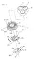
- a head frame 30 is detachably fitted on the housing 12 so that the head frame 30 covers the drive shaft holder 26. As seen in Figure 2, three through holes 31 are opened in the head frame 30 so that three shaving units described below are installed in these holes 31 from the inside of the housing 12.
- Each shaving unit 34 comprises an outer cutter 36 and an inner cutter 38.
- the outer cutter 36 as seen in Figure 2, has a round shaving surface 37 on its top surface. Radial slits 37a are opened over the entire shaving surface 37.
- An outer cutter cap 35 is fitted in the center of the outer cutter 36.
- a ring-shaped guide groove 37b is formed at an intermediate point of the shaving surface 37, so that the shaving surface 37 is divided into two (outside and inside) sections in the form of concentric circles.
- the outer cutter 36 has a flange 36a at the lower end. The flange 36a comes into contact with the inside surface of the head frame 30 so that the outer cutter 36 cannot slip off.
- a cut-out 36b is formed at one part of the outer cutter 36.
- the outer cutter 36 is prevented from rotating by a combination of the cut-out 36b and a stopper (not shown) formed on the inside surface of the head frame 30.
- the inner cutter 38 has a plurality of arms 39a extended upwardly from the outer edge portion of a cutter disk 39, and cutting blades 40 are formed at the ends of these arms 39a so that they slide on the back surface of the outer cutter 36.
- the ends of these cutting blades 40 are split into two branches so that each of the split ends can fit in a respective one of the two circular sections of the shaving surface 37 of the outer cutter 36.
- the cutting blades 40 are inclined in the direction of rotation of the inner cutter (as shown by an arrow in Figure 2).
- An engagement hole 39b is opened in the cutter disk 39 of the inner cutter 38.
- the engagement hole 39b is formed, for example, in a square shape with a semicircular cut-out formed on each side of the square hole 39b.
- Into this engagement hole 39b of the inner cutter 38 is inserted a portion of a fan assembly 42 to make a secure engagement between the inner cutter 38 and the fan assembly 42.
- the fan assembly 42 is comprised of a base block 43, at least one fan blade 44 and an engagement projection 43a.
- the base block 43 is a shallow cylinder and the engagement projection 43a is formed on the top surface of this base block 43.
- the engagement projection 43a has the same shape as the engagement hole 39b of the inner cutter 38 so as to be snugly fitted into the engagement hole 39b.
- an engagement hole 43b is formed in the bottom of the base block 43 so that a transmission tongue 24c formed at the tip end of the drive shaft 24 is inserted into this engagement hole 43b.
- the surrounding areas of the engagement hole 43b are rounded for an easy insertion of the transmission tongue 24c of the drive shaft 24 into the engagement hole 43b.
- Figure 2 shows a fan assembly 42 with two fan blades 44 that extend in a radial direction from the circumferential surface of the base block 43. These fan blades 44 are inclined in the same direction as the cutting blades 40 of the inner cutter 38, the direction of inclination of the fan blades 44 being the rotational direction of the inner cutter 38 and the fan assembly 42.
- reference numeral 46 designates a shaving unit retaining plate which is installed on the back surface of the head frame 30.
- the shaving unit retaining plate 46 is fixed to the head frame 30 via a supporting shaft 48.
- the supporting shaft 48 has a threaded portion 48a that is screwed into the center hole of the head frame 30.
- the supporting shaft 48 has a flange 48b at the lower end, and a spring 50 is installed on the supporting shaft 48 so that the spring 50 is between the flange 48b and the shaving unit retaining plate 46.
- the upper end of the supporting shaft 48 is restrained by a retaining ring 49.
- the shaving unit retaining plate 46 is urged upwardly (in the drawings) by the spring 50.
- the shaving unit retaining plate 46 has through holes 51 which positionally correspond to the holes 31 formed in the head frame 30.
- supporting tubes 51a project upwardly from the inside rims of these holes 51, and the upper ends of these supporting tubes 51a are in contact with the flanges 36a of the outer cutters 36.
- the shaving surfaces 37 of the outer cutters 36 are pressed toward the inside of the razor 10 so that the outer cutters 36 are pushed inwardly against the driving force of the spring 50.
- shaving is performed with the razor snugly fitting the facial contour. Since the drive shafts 24 that hold the fan assemblies 42 are also supported by springs 21, the drive shafts 24 can move to and fro in the axial directions together with the shaving units 34.
- the shaving unit retaining plate 46 has a ring section 52 in each supporting part 53.
- the ring section 52 is supported by the drive shaft 24 so as not to come into contact with the fan assembly 42 during shaving.
- the shaving unit retaining plate 46 is fixed to the back surface of the head frame 30 by the supporting shaft 48. Accordingly, when the head frame 30 is removed from the razor 10, the shaving units 34 and the fan assemblies 42 do not fall away from the shaving unit retaining plate 46 because of the provision of the ring sections 52 of the supporting tubes 51a of the shaving unit retaining plate 46.
- the electric razor 10 is switched on, and shaving is performed by pressing outer cutters 36 against the skin. Whiskers penetrating the outer cutters 36 through the radial slits 37a of the shaving surface 37 are sheared by the outer cutters 36 and the cutting blades 40 of the inner cutters 38 which are rotated by the motor 16 via the drive gear 18, the transmission gears 20 and the drive shafts 24. The sheared whiskers are driven downwardly while being sucked in by the fan blades 44 of the fan assemblies 42 which rotate together with the inner cutters 38.
- the sheared whiskers are guided by the supporting tubes 51a and drop without being scattered or coming out of the outer cutters 36.
- the whiskers are collected in the receptacle shaped drive shaft holder 26; and once the whiskers are in the drive shaft holder 26, they do not fly out through the slits 37a of the outer cutters 36.
- the head frame 30 When whiskers are collected in the drive shaft holder 26, the head frame 30 is detached and the whiskers are removed from the drive shaft holder 26 by a brush, etc. Since not much of the shaving debris sticks to the shaving units 34 because of the function of the fan assemblies 42, there is no great need to clean the shaving units 34. If, however, the shaving units 34 need to be cleaned, they can be removed from the head frame 30 by unscrewing the supporting shaft 48.
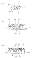
- FIG. 5 shows a modified fan assembly 42.
- This fan assembly 42 has ten fan blades 44 extending radially from the circumferential surface of the base block 43.
- the remaining structure of this fan assembly 42 is the same as the fan assembly shown in Figure 2.
- the fan blades 44 can be in any number.
- the arrow in Figure 5 indicates the direction in which the fan assembly 42 is rotated in use.
- Figure 6 shows the arrangement of one of the inner cutters 38 with a fan assembly 42 which has a plurality of fan blades 44.
- the cutting blades 40 of the inner cutter 38 are the same in number as the fan blades 44 of the fan assembly 42.
- the cutting blades 40 and fan blades 44 are also designed so as to be at the same angle of inclination.
- the lower ends of the cutting blades 40 and the upper ends of the fan blades 44 are set to be in contact so that the cutting blades 40 and the fan blades 44 are flush and continuous to each other.
- the cutting blades 40 and the fan blades 44 can however be positioned so that the surfaces thereof are not flush in the circumferential direction.
- the fan assembly 42 has ten fan blades 44; however, there is no particular restriction on the number of the fan blades 44 that can be used.
- FIG. 7 shows a modified arrangement of the inner cutter 38 and fan assembly 42.
- the fan blades 44 of the fan assembly 42 are positioned between the cutting blades 40 of the inner cutter 38.
- the inclination of the fan blades 44 is set to be the same as that of the cutting blades 40.
- the fan blades 44 are extended in the axial direction of the base block 43 so that the upper edges of the fan blades 44 can be located immediately beneath the back surface of the shaving surface 37 of an outer cutter 36.
- the upper end of each fan blade 44 is branched into two. With these fan blades 44, the branched upper ends of the fan blades 44 can scrape off the shaving debris, if any, sticking to the back surfaces of the circularly divided shaving surface 37 of the outer cutter 36.
- the fan blades 44 can also be in any number.
- the inner cutters 38 and the fan assemblies 42 are coupled together via the engagement holes 39b opened in the inner cutters 38 and the engagement projections 43a formed on the fan assemblies 42.
- this engagement relationship can be reversed. It is also possible to use other engagement structures.
- the inner cutters 38 are made out of metal, and the fan assemblies 42 a synthetic resin.
- the fan assemblies 42 and the inner cutters 38 can be made in a single unit from a single material.
- an inner cutter 38 may have not only the cutting blades 40 but in addition also the fan blades 44.
- whiskers sheared by the shaving units 34 are blown in by the suction force of the fan assemblies 42.
- whiskers cut by the outer cutters and inner cutters are scraped off and pulled by the suction force of the fan assemblies so that the whiskers are blown into and collected in a receptacle element which is the drive shaft holder in the described embodiment. Accordingly, not much of the shaving debris adheres to the shaving units which are difficult to clean. Thus, cleaning of the electric razor is made easier.
- the whiskers entering through the slits of the outer cutter are pulled into the razor body and extended. Thus, the cutting of the whiskers can be done more efficiently.
- the outer cutters are supported from the inside of the razor housing by the supporting tubes, and the inner cutters and fan assembly are positioned inside these supporting tubes. Accordingly, the scattering of the shaving debris is prevented. In addition, the adhesion of shaving debris to the inside walls of the supporting tubes can be prevented by the rotation of the fan blades.
Landscapes
- Life Sciences & Earth Sciences (AREA)
- Forests & Forestry (AREA)
- Engineering & Computer Science (AREA)
- Mechanical Engineering (AREA)
- Dry Shavers And Clippers (AREA)
- Glass Compositions (AREA)
- Reverberation, Karaoke And Other Acoustics (AREA)
- Iron Core Of Rotating Electric Machines (AREA)
- Organic Low-Molecular-Weight Compounds And Preparation Thereof (AREA)
- Air Humidification (AREA)
Abstract
Description
Claims (5)
- An electric razor comprising: a head frame (30) installed in a freely detachable manner over a drive shaft holder (26), said drive shaft holder (26) being receptacle shaped for collecting shaving debris, so that said head frame (30) covers said drive shaft holder (26); shaving units (34) installed on a back side of said head frame (30), each of said shaving units (34) consisting of an outer cutter (36) with slits (37a) for introducing whiskers and an inner cutter (38) which in use rotates on a back surface of said outer cutter (36) to shear whiskers introduced through said slits (37a), each inner cutter (38) having cutting blades (40) which slide on a back surface of a corresponding outer cutter (36), said cutting blades (40) being formed at ends of a plurality of arms (39a) which are extended upwardly from a central part (39) of said inner cutter (38) and being inclined in a direction of rotation; drive shafts (24) projecting from said drive shaft holder (26) which are coupled to said inner cutters (38) and connected to a driving source (16); and a fan assembly (42) including a plurality of fan blades (44) which in use is rotated together with said inner cutters (38) by a driving force for said drive shafts (24); characterized in that said electric razor comprises a plurality of fan assemblies (42) which are installed coaxially with said inner cutters (38) so as in use to rotate together with said inner cutters (38), in that said fan blades (44) are located between said cutting blades (40), and in that said fan blades (44) are inclined in substantially the same direction as said cutting blades (40).
- An electric razor according to claim 1, wherein each of said fan assemblies (42) comprises a base block (43), an engagement hole (43b) engageable with a corresponding drive shaft (24), fan blades (44) extended in a radial direction from a circumferential surface of said base block (43), and an engagement projection (43a) formed on an upper surface of said base block (43) so as to engage with a corresponding inner cutter (38).
- An electric razor according to claim 1 or 2, wherein upper ends of said fan blades (44) are positioned near a back surface of a respective outer cutter (38).
- An electric razor according to claim 3, further comprising supporting tubes (51a) which support said outer cutters (36) by pressing said outer cutters (36) from inside of said razor so that said inner cutters (38) and fan assemblies (42) are positioned inside said supporting tubes (51a).
- An electric razor according to any one of claims 1 to 3, further comprising a shaving unit retaining plate (46) mounted to said head frame (30) via a screw, said shaving unit retaining plate (46) being provided with a plurality of supporting tubes (51a) that accommodate said shaving units (34).
Priority Applications (1)
| Application Number | Priority Date | Filing Date | Title |
|---|---|---|---|
| EP96200189A EP0713752B1 (en) | 1993-01-08 | 1993-12-21 | Electric razor |
Applications Claiming Priority (2)
| Application Number | Priority Date | Filing Date | Title |
|---|---|---|---|
| JP5018230A JPH06205884A (en) | 1993-01-08 | 1993-01-08 | Electric razor |
| JP18230/93 | 1993-01-08 |
Related Child Applications (2)
| Application Number | Title | Priority Date | Filing Date |
|---|---|---|---|
| EP96200189A Division EP0713752B1 (en) | 1993-01-08 | 1993-12-21 | Electric razor |
| EP96200189.7 Division-Into | 1993-12-21 |
Publications (2)
| Publication Number | Publication Date |
|---|---|
| EP0606000A1 EP0606000A1 (en) | 1994-07-13 |
| EP0606000B1 true EP0606000B1 (en) | 1998-03-11 |
Family
ID=11965871
Family Applications (2)
| Application Number | Title | Priority Date | Filing Date |
|---|---|---|---|
| EP96200189A Expired - Lifetime EP0713752B1 (en) | 1993-01-08 | 1993-12-21 | Electric razor |
| EP93310390A Expired - Lifetime EP0606000B1 (en) | 1993-01-08 | 1993-12-21 | Electric razor |
Family Applications Before (1)
| Application Number | Title | Priority Date | Filing Date |
|---|---|---|---|
| EP96200189A Expired - Lifetime EP0713752B1 (en) | 1993-01-08 | 1993-12-21 | Electric razor |
Country Status (10)
| Country | Link |
|---|---|
| US (1) | US5394611A (en) |
| EP (2) | EP0713752B1 (en) |
| JP (1) | JPH06205884A (en) |
| AT (2) | ATE215431T1 (en) |
| CA (1) | CA2111626C (en) |
| DE (3) | DE606000T1 (en) |
| ES (1) | ES2058042T1 (en) |
| GR (1) | GR940300061T1 (en) |
| HK (1) | HK1005773A1 (en) |
| MX (1) | MX9400302A (en) |
Cited By (1)
| Publication number | Priority date | Publication date | Assignee | Title |
|---|---|---|---|---|
| CN107696071A (en) * | 2017-10-10 | 2018-02-16 | 无锡市南长实验中学 | A kind of shaver for being convenient to clean beard |
Families Citing this family (19)
| Publication number | Priority date | Publication date | Assignee | Title |
|---|---|---|---|---|
| US5625950A (en) * | 1994-07-19 | 1997-05-06 | U.S. Philips Corporation | Shaving apparatus |
| JP3682997B2 (en) * | 1995-01-11 | 2005-08-17 | 株式会社泉精器製作所 | Electric razor |
| US6032365A (en) * | 1997-02-24 | 2000-03-07 | James L. Hodges | Slotted rotary shaver |
| DE10018486A1 (en) * | 2000-04-14 | 2001-10-18 | Philips Corp Intellectual Pty | Cleaning device for a shaver |
| JP4635166B2 (en) * | 2000-11-28 | 2011-02-16 | 株式会社泉精器製作所 | Rotary electric razor |
| JP2005312523A (en) * | 2004-04-27 | 2005-11-10 | Izumi Products Co | Rotary electric shaver |
| US20060230619A1 (en) * | 2005-04-18 | 2006-10-19 | Rovcal, Inc. | Hair clipper with vacuum collection system |
| JP2007135991A (en) * | 2005-11-21 | 2007-06-07 | Izumi Products Co | Rotary electric shaver |
| JP5215301B2 (en) * | 2006-07-14 | 2013-06-19 | コーニンクレッカ フィリップス エレクトロニクス エヌ ヴィ | Shaver with space for collecting hair to be excised |
| US9009978B2 (en) | 2009-01-09 | 2015-04-21 | Koninklijke Philips N.V. | Shaver having spaces for collecting cut-off hairs |
| US9027251B2 (en) | 2009-04-29 | 2015-05-12 | Spectrum Brands, Inc. | Rotary electric shaver |
| IT1402976B1 (en) * | 2010-12-06 | 2013-09-27 | Zizzari | PERFECT ELECTRIC RAZOR |
| US8838232B1 (en) * | 2012-03-12 | 2014-09-16 | Thomas Edward Schwerin | Multifunction electric razor having an electrical stimulator |
| CN103273511B (en) * | 2013-05-21 | 2015-09-09 | 宁波美钻机电有限公司 | A kind of rotary shaver |
| US9919438B2 (en) * | 2016-02-03 | 2018-03-20 | Dave Knapp | Personal grooming assembly |
| EP3647001A1 (en) * | 2018-11-05 | 2020-05-06 | Koninklijke Philips N.V. | Shaving apparatus with improved cap functionality |
| EP3647002A1 (en) * | 2018-11-05 | 2020-05-06 | Koninklijke Philips N.V. | A cutting unit for a shaving apparatus comprising a hair transporting fan structure |
| CN112518807A (en) * | 2020-11-16 | 2021-03-19 | 陈金花 | Electric shaver |
| CN221248917U (en) * | 2023-11-25 | 2024-07-02 | 温州劲科电器有限公司 | Shaver |
Family Cites Families (14)
| Publication number | Priority date | Publication date | Assignee | Title |
|---|---|---|---|---|
| US2283865A (en) * | 1938-06-10 | 1942-05-19 | Casco Products Corp | Shaving machine |
| FR1103679A (en) * | 1954-07-05 | 1955-11-04 | Electric razor | |
| JPS5144462B2 (en) * | 1971-08-19 | 1976-11-29 | ||
| AU6159673A (en) * | 1972-11-17 | 1975-04-24 | Bissell Inc | Rotary shaver |
| US4089110A (en) * | 1976-03-08 | 1978-05-16 | Rasco Darius K | Shaving means |
| JPS5719084Y2 (en) * | 1976-05-26 | 1982-04-21 | ||
| NL7811228A (en) * | 1978-11-14 | 1980-05-19 | Philips Nv | SHAVER. |
| NL8003669A (en) * | 1980-06-25 | 1982-01-18 | Philips Nv | SHAVER. |
| JPS5729392A (en) * | 1980-07-29 | 1982-02-17 | Matsushita Electric Works Ltd | Electric razor |
| JPS5793077A (en) * | 1980-11-29 | 1982-06-09 | Matsushita Electric Works Ltd | Rotary type electric razor |
| US4847996A (en) * | 1987-06-10 | 1989-07-18 | Ayzik Blykharov | Device for facilitating cleaning of rotary razor, and rotary razor provided therewith |
| JPS647293U (en) * | 1987-06-27 | 1989-01-17 | ||
| JPS6468561A (en) * | 1987-09-04 | 1989-03-14 | Matsushita Electric Works Ltd | Wool ball remover |
| DE3919022A1 (en) * | 1989-06-10 | 1989-12-28 | Dieter Meyer | METHOD AND DEVICE FOR VACUUM-ASSISTED DRY SHAVE |
-
1993
- 1993-01-08 JP JP5018230A patent/JPH06205884A/en active Pending
- 1993-12-07 US US08/163,378 patent/US5394611A/en not_active Expired - Lifetime
- 1993-12-16 CA CA002111626A patent/CA2111626C/en not_active Expired - Fee Related
- 1993-12-21 DE DE0606000T patent/DE606000T1/en active Pending
- 1993-12-21 EP EP96200189A patent/EP0713752B1/en not_active Expired - Lifetime
- 1993-12-21 DE DE69331784T patent/DE69331784T2/en not_active Expired - Fee Related
- 1993-12-21 EP EP93310390A patent/EP0606000B1/en not_active Expired - Lifetime
- 1993-12-21 DE DE69317394T patent/DE69317394T2/en not_active Expired - Fee Related
- 1993-12-21 AT AT96200189T patent/ATE215431T1/en not_active IP Right Cessation
- 1993-12-21 ES ES93310390T patent/ES2058042T1/en active Pending
- 1993-12-21 AT AT93310390T patent/ATE163878T1/en active
-
1994
- 1994-01-06 MX MX9400302A patent/MX9400302A/en not_active IP Right Cessation
- 1994-09-30 GR GR940300061T patent/GR940300061T1/en unknown
-
1998
- 1998-06-04 HK HK98104886A patent/HK1005773A1/en not_active IP Right Cessation
Cited By (1)
| Publication number | Priority date | Publication date | Assignee | Title |
|---|---|---|---|---|
| CN107696071A (en) * | 2017-10-10 | 2018-02-16 | 无锡市南长实验中学 | A kind of shaver for being convenient to clean beard |
Also Published As
| Publication number | Publication date |
|---|---|
| ATE215431T1 (en) | 2002-04-15 |
| GR940300061T1 (en) | 1994-09-30 |
| CA2111626A1 (en) | 1994-07-09 |
| HK1013042A1 (en) | 1999-08-13 |
| DE69317394D1 (en) | 1998-04-16 |
| HK1005773A1 (en) | 1999-01-22 |
| ES2058042T1 (en) | 1994-11-01 |
| MX9400302A (en) | 1994-08-31 |
| EP0713752A2 (en) | 1996-05-29 |
| EP0606000A1 (en) | 1994-07-13 |
| ATE163878T1 (en) | 1998-03-15 |
| US5394611A (en) | 1995-03-07 |
| DE606000T1 (en) | 1995-04-20 |
| DE69317394T2 (en) | 1998-07-02 |
| DE69331784T2 (en) | 2002-10-31 |
| EP0713752B1 (en) | 2002-04-03 |
| DE69331784D1 (en) | 2002-05-08 |
| JPH06205884A (en) | 1994-07-26 |
| EP0713752A3 (en) | 1997-12-29 |
| CA2111626C (en) | 1999-08-31 |
Similar Documents
| Publication | Publication Date | Title |
|---|---|---|
| EP0713752B1 (en) | Electric razor | |
| HK1005773B (en) | Electric razor | |
| EP0611043B1 (en) | Electric razor | |
| HK1005707B (en) | Electric razor | |
| CA1093804A (en) | Knife | |
| US5012576A (en) | Personal hair trimmer | |
| US5123430A (en) | Cutter device for fingernails or toenails | |
| US4089110A (en) | Shaving means | |
| CA1286116C (en) | Lawn mower cutting assembly | |
| EP0378266A1 (en) | Shaving apparatus | |
| CN1404432A (en) | Accessories for electric shavers | |
| JPH0333473B2 (en) | ||
| HK1013042B (en) | Electric razor | |
| EP1231034A1 (en) | Dry shaver for variable height of cut | |
| US3298101A (en) | Counter-rotating head electric razor | |
| US5909928A (en) | Electrical hair remover device and method | |
| EP0997066B1 (en) | A blade-whetting apparatus for bladed wheels | |
| US2933809A (en) | Interchangeable cutter head dry shaver | |
| US1941583A (en) | Power operated shaving apparatus | |
| JP2635110B2 (en) | Inner blade for electric shaving apparatus and electric shaving apparatus | |
| GB2045046A (en) | Lawn edger | |
| GB1562948A (en) | Powered cutting or stripping tools | |
| GB2038691A (en) | Electric razor | |
| EP0145218A1 (en) | Improvements in or relating to lawn maintenance equipment | |
| JPH0451750Y2 (en) |
Legal Events
| Date | Code | Title | Description |
|---|---|---|---|
| PUAI | Public reference made under article 153(3) epc to a published international application that has entered the european phase |
Free format text: ORIGINAL CODE: 0009012 |
|
| AK | Designated contracting states |
Kind code of ref document: A1 Designated state(s): AT BE CH DE DK ES FR GB GR IE IT LI LU MC NL PT SE |
|
| ITCL | It: translation for ep claims filed |
Representative=s name: JACOBACCI CASETTA & PERANI S.P.A. |
|
| 17P | Request for examination filed |
Effective date: 19940714 |
|
| TCAT | At: translation of patent claims filed | ||
| REG | Reference to a national code |
Ref country code: ES Ref legal event code: BA2A Ref document number: 2058042 Country of ref document: ES Kind code of ref document: T1 |
|
| TCNL | Nl: translation of patent claims filed | ||
| EL | Fr: translation of claims filed |
Free format text: BO 94/38 PAGE 191:LIRE 0606000 AU LIEU DE 0606600 |
|
| DET | De: translation of patent claims | ||
| 17Q | First examination report despatched |
Effective date: 19950919 |
|
| GRAG | Despatch of communication of intention to grant |
Free format text: ORIGINAL CODE: EPIDOS AGRA |
|
| GRAG | Despatch of communication of intention to grant |
Free format text: ORIGINAL CODE: EPIDOS AGRA |
|
| GRAG | Despatch of communication of intention to grant |
Free format text: ORIGINAL CODE: EPIDOS AGRA |
|
| GRAH | Despatch of communication of intention to grant a patent |
Free format text: ORIGINAL CODE: EPIDOS IGRA |
|
| GRAH | Despatch of communication of intention to grant a patent |
Free format text: ORIGINAL CODE: EPIDOS IGRA |
|
| GRAA | (expected) grant |
Free format text: ORIGINAL CODE: 0009210 |
|
| AK | Designated contracting states |
Kind code of ref document: B1 Designated state(s): AT BE CH DE DK ES FR GB GR IE IT LI LU MC NL PT SE |
|
| PG25 | Lapsed in a contracting state [announced via postgrant information from national office to epo] |
Ref country code: LI Free format text: LAPSE BECAUSE OF FAILURE TO SUBMIT A TRANSLATION OF THE DESCRIPTION OR TO PAY THE FEE WITHIN THE PRESCRIBED TIME-LIMIT Effective date: 19980311 Ref country code: GR Free format text: LAPSE BECAUSE OF NON-PAYMENT OF DUE FEES Effective date: 19980311 Ref country code: CH Free format text: LAPSE BECAUSE OF FAILURE TO SUBMIT A TRANSLATION OF THE DESCRIPTION OR TO PAY THE FEE WITHIN THE PRESCRIBED TIME-LIMIT Effective date: 19980311 Ref country code: BE Free format text: LAPSE BECAUSE OF FAILURE TO SUBMIT A TRANSLATION OF THE DESCRIPTION OR TO PAY THE FEE WITHIN THE PRESCRIBED TIME-LIMIT Effective date: 19980311 Ref country code: AT Free format text: LAPSE BECAUSE OF FAILURE TO SUBMIT A TRANSLATION OF THE DESCRIPTION OR TO PAY THE FEE WITHIN THE PRESCRIBED TIME-LIMIT Effective date: 19980311 |
|
| REF | Corresponds to: |
Ref document number: 163878 Country of ref document: AT Date of ref document: 19980315 Kind code of ref document: T |
|
| XX | Miscellaneous (additional remarks) |
Free format text: TEILANMELDUNG 96200189.7 EINGEREICHT AM 26/01/96. |
|
| REG | Reference to a national code |
Ref country code: CH Ref legal event code: EP |
|
| REF | Corresponds to: |
Ref document number: 69317394 Country of ref document: DE Date of ref document: 19980416 |
|
| ET | Fr: translation filed | ||
| ITF | It: translation for a ep patent filed | ||
| PG25 | Lapsed in a contracting state [announced via postgrant information from national office to epo] |
Ref country code: SE Free format text: LAPSE BECAUSE OF FAILURE TO SUBMIT A TRANSLATION OF THE DESCRIPTION OR TO PAY THE FEE WITHIN THE PRESCRIBED TIME-LIMIT Effective date: 19980611 Ref country code: DK Free format text: LAPSE BECAUSE OF FAILURE TO SUBMIT A TRANSLATION OF THE DESCRIPTION OR TO PAY THE FEE WITHIN THE PRESCRIBED TIME-LIMIT Effective date: 19980611 |
|
| PG25 | Lapsed in a contracting state [announced via postgrant information from national office to epo] |
Ref country code: PT Free format text: LAPSE BECAUSE OF FAILURE TO SUBMIT A TRANSLATION OF THE DESCRIPTION OR TO PAY THE FEE WITHIN THE PRESCRIBED TIME-LIMIT Effective date: 19980615 |
|
| REG | Reference to a national code |
Ref country code: IE Ref legal event code: FG4D Free format text: 79269 |
|
| REG | Reference to a national code |
Ref country code: CH Ref legal event code: PL |
|
| PG25 | Lapsed in a contracting state [announced via postgrant information from national office to epo] |
Ref country code: ES Free format text: LAPSE BECAUSE OF FAILURE TO SUBMIT A TRANSLATION OF THE DESCRIPTION OR TO PAY THE FEE WITHIN THE PRESCRIBED TIME-LIMIT Effective date: 19980921 |
|
| PG25 | Lapsed in a contracting state [announced via postgrant information from national office to epo] |
Ref country code: LU Free format text: LAPSE BECAUSE OF NON-PAYMENT OF DUE FEES Effective date: 19981221 Ref country code: IE Free format text: LAPSE BECAUSE OF NON-PAYMENT OF DUE FEES Effective date: 19981221 |
|
| PLBE | No opposition filed within time limit |
Free format text: ORIGINAL CODE: 0009261 |
|
| STAA | Information on the status of an ep patent application or granted ep patent |
Free format text: STATUS: NO OPPOSITION FILED WITHIN TIME LIMIT |
|
| 26N | No opposition filed | ||
| PG25 | Lapsed in a contracting state [announced via postgrant information from national office to epo] |
Ref country code: MC Free format text: LAPSE BECAUSE OF NON-PAYMENT OF DUE FEES Effective date: 19990630 |
|
| REG | Reference to a national code |
Ref country code: GB Ref legal event code: IF02 |
|
| PGFP | Annual fee paid to national office [announced via postgrant information from national office to epo] |
Ref country code: FR Payment date: 20041231 Year of fee payment: 12 Ref country code: NL Payment date: 20041231 Year of fee payment: 12 Ref country code: DE Payment date: 20041231 Year of fee payment: 12 |
|
| PG25 | Lapsed in a contracting state [announced via postgrant information from national office to epo] |
Ref country code: IT Free format text: LAPSE BECAUSE OF NON-PAYMENT OF DUE FEES Effective date: 20051221 |
|
| PG25 | Lapsed in a contracting state [announced via postgrant information from national office to epo] |
Ref country code: NL Free format text: LAPSE BECAUSE OF NON-PAYMENT OF DUE FEES Effective date: 20060701 Ref country code: DE Free format text: LAPSE BECAUSE OF NON-PAYMENT OF DUE FEES Effective date: 20060701 |
|
| PG25 | Lapsed in a contracting state [announced via postgrant information from national office to epo] |
Ref country code: FR Free format text: LAPSE BECAUSE OF NON-PAYMENT OF DUE FEES Effective date: 20060831 |
|
| NLV4 | Nl: lapsed or anulled due to non-payment of the annual fee |
Effective date: 20060701 |
|
| REG | Reference to a national code |
Ref country code: FR Ref legal event code: ST Effective date: 20060831 |
|
| PGFP | Annual fee paid to national office [announced via postgrant information from national office to epo] |
Ref country code: GB Payment date: 20071231 Year of fee payment: 15 |
|
| GBPC | Gb: european patent ceased through non-payment of renewal fee |
Effective date: 20081221 |
|
| PG25 | Lapsed in a contracting state [announced via postgrant information from national office to epo] |
Ref country code: GB Free format text: LAPSE BECAUSE OF NON-PAYMENT OF DUE FEES Effective date: 20081221 |