EP0605148A2 - Securing system for centrifuge chamber - Google Patents
Securing system for centrifuge chamber Download PDFInfo
- Publication number
- EP0605148A2 EP0605148A2 EP93310148A EP93310148A EP0605148A2 EP 0605148 A2 EP0605148 A2 EP 0605148A2 EP 93310148 A EP93310148 A EP 93310148A EP 93310148 A EP93310148 A EP 93310148A EP 0605148 A2 EP0605148 A2 EP 0605148A2
- Authority
- EP
- European Patent Office
- Prior art keywords
- clamp arm
- chamber
- chuck
- pivot
- securing means
- Prior art date
- Legal status (The legal status is an assumption and is not a legal conclusion. Google has not performed a legal analysis and makes no representation as to the accuracy of the status listed.)
- Granted
Links
Images


Classifications
-
- B—PERFORMING OPERATIONS; TRANSPORTING
- B04—CENTRIFUGAL APPARATUS OR MACHINES FOR CARRYING-OUT PHYSICAL OR CHEMICAL PROCESSES
- B04B—CENTRIFUGES
- B04B7/00—Elements of centrifuges
-
- B—PERFORMING OPERATIONS; TRANSPORTING
- B04—CENTRIFUGAL APPARATUS OR MACHINES FOR CARRYING-OUT PHYSICAL OR CHEMICAL PROCESSES
- B04B—CENTRIFUGES
- B04B7/00—Elements of centrifuges
- B04B7/08—Rotary bowls
Definitions
- This invention relates to an improvement in securing or chucking, in a system for separating and irradiating multi-component fluids and, in particular, to the use of such systems in the field of treating cells with photoactivatable compounds by radiation, which activates the compounds to effect cellular change.
- Numerous human disease states of the body respond favorably to the treatment of selected bodily fluid components, such as those found in blood, by visible or ultraviolet light irradiation. Such treatment may be effective to eliminate immunogenicity in cells, inactive or kill selected cells, inactivate viruses or bacteria, or activate desirable immune responses. Certain forms of treatment with light irradiation may be effective without the introduction of outside agents or compounds, while others may involve the introduction of specific agents or catalysts. Among the latter treatment techniques is the use of photoactivatable agents to regulate the population of leukocytes. It is well-known that a number of human disease states may be characterized by the over production of certain types of leukocytes, including lymphocytes, in comparison to other populations of cells which normally comprise whole blood. Excessive or abnormal lymphocyte populations result in numerous adverse effects in patients including the functional impairment of bodily organs, leukocyte mediated autoimmune diseases and leukemia related disorders many of which often ultimately result in fatality.
- U.S. Patent Nos. 4,321,919; 4,398,906; 4,428,744 and 4,464,166 to Edelson describe methods for treating blood whereby the operation or viability of certain cellular population may be moderated thereby providing relief for these patients.
- the methods comprise treating the blood with a dissolved photactivatable drug, such as psoralen, which is capable of forming photoaducts with DNA in the presence of ultraviolet (U.V.) radiation. It is believed that covalent bonding results between the psoralen and the lymphocyte nucleic acid thereby effecting metabolic inhibition of the treated cells.
- the cells are returned to the patient where they are thought to be cleared by natural processes but at an accelerated pace, believed attributable to disruption of membrane integrity, alteration of DNA within the cell, or like conditions often associated with substantial loss of cellular effectiveness or viability.
- the current system for retaining the removable separation/irradiation chamber utilizes either screws, which are subject to over- or under-tightening with each use, along with O-rings for gripping when the screws are tightened.
- the O-rings present an additional problem that make it difficult to insert or release the centrifuge bowl unless the O-rings are regularly cleaned and frequently greased.
- vacuum systems are available to retain the removable chamber while it is being rotated during use. Although vacuum systems are convenient, they are fairly complicated requiring pumps and rotating seals. In addition, this type of system has components that can be contaminated by a spill and is difficult to clean.
- an apparatus that automatically retains the removable chamber during operation by providing a clamp arm that has two ends.
- the first acts as a securing means, the second contains the clamp arm center of mass.
- the clamp arm is pivoted on the rotating chuck near the interface of the rotating chuck interior and the removable chamber exterior.
- the pivot allows for rotation of the clamp arm about the pivot, the pivot being located between the first end with the securing means and the second end containing the center of mass.
- the preferred embodiment contains on the clamp arm end containing the securing means, a bevelled end so that the clamp arm swings out of the way upon insertion or removal of the chamber.
- the preferred embodiment also includes a stop pin which prevents the end of the clamp arm containing the center of mass from rotating under the rim of the chamber and interfering with its insertion.
- Fig. 1 is a cross sectional view of a prior art means for securing the removable chamber into the rotatable chuck of the separating and irradiating system.
- Fig. 2 is an isometric view showing the rotatable chuck and removable chamber as well as the securing system of the present invention.
- Fig. 3 is an isometric view of a clamp arm which forms one of the elements of the present invention.
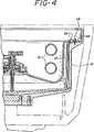
- Fig. 4 is a cross sectional view of the present invention showing the improved chamber securing apparatus as it would be positioned during operational rotation of the chuck and chamber.
- FIG. 1 there is shown a multi-component bodily fluid separating and irradiation apparatus employing one of the prior art systems for securing the chamber 10 within chuck 12.
- This prior art securing system 14 is comprised of screw 16 which is locked into the chuck 12. This screw passes through nut 18 which has matching mating threads for the screw as well as passing through clamp ring 20 which is unthreaded and does not interact with the screw.
- O-ring 22 is compressed by clamp ring 20 when nut 18 is tightened down on clamp ring 20.
- Nut 18 is free to turn between the top of screw 16 and a tightened position fully down on clamp ring 20 in about 1 to 11 ⁇ 2 turns.
- the chuck 12 and chamber 10 are shown in isolation without the remainder of the blood separation and irradiation system. Also shown is the improved retaining system 24 of the present invention.
- This retaining system comprises clamp arm 26 which is free to rotate at least partially about pivot 28. Pivot 28 is constructed of stainless steal shoulder screws. Rotation of the clamp arm 26 is limited by stop pin 30.
- clamp arm 26 is shown in greater detail.
- Clamp arm 26 is comprised of pivot point 32 wherein pivot 28 mates.
- Clamp arm 26 is comprised of two portions: a first portion having a securing means 34 and a second portion containing the clamp arm center of mass 36.
- chuck 12 rotates in the direction indicated by the arrow, although this is merely a matter of design choice and the device of the present invention will work equally well with rotation counter to that shown.
- This rotation causes the center of mass 36 to move away from the central axis of the chamber ⁇ chuck combination, causing clamp arm 26 to rotate about pivot 28 in the direction of the arrows shown at either end of the clamp arm.
- This causes securing means 34 to move above chamber 10.
- this direction of rotation of the clamp arm is a design choice, and the present invention would work equally well with the clamp arm designed to rotate in the other direction.
- FIG. 4 there is shown the separation irradiation system with the apparatus of the present invention taking the position it assumes during operational rotation of the chuck 12.
- securing means 34 with its chamfered edge rotates over the ledge of chuck 12 and above a portion of chamber 10. In this way, chamber 10 is secured within chuck 12 during operational rotation of the device.
- the bevelled portions of securing means 34 preferably at angles of 45°, allows chamber 10 to be removed and inserted when chuck 12 is stationary by translating upward or downward force on the chamber during removal or insertion into translational force rotating clamp arm 26 out of the way of chamber 12.
- stop pin 30 located on chuck 12 is positioned to prevent the second portion of clamp arm 26 containing center of mass 36 from inadvertently becoming positioned under the edge of the chamber 10 when the chuck 12 is not rotating, preventing insertion of the chamber.
- the use of a stop pin is preferable to attempting to implement a bevel on this end because of the end's width and thinness.
- a bias means may be used, such as a spring, to provide a small force causing the clamp arm 26 to return to a desired stable position when the unit is not in operation.
- An embodiment implementing by conventional means a bias means such as a spring, and elimination of the stop pin is readily apparent to one working in the mechanical arts. This approach, however, has the disadvantages of using small parts that can be loosened and lost and are difficult to clean, and is therfore not preferred.
- two or more of the above described apparatus are used to hold the chamber in place during operation. It has been found that gravity alone is sufficient to hold the chamber in place until the chuck begins to turn when centrifugal force acts on the clamp arm to rotate the arm about pivot 28 in the desired direction.
- the chamber 10 can be lifted directly out of chuck 12 because the bevel angels at 45° are sufficient to prevent jamming the arm against the rim of the bowl. Specifically, it was calculated that if there were no friction, the force to remove the chamber should be approximately 19 pounds. Under actual conditions, it was measured that the chamber could be removed with a direct upward pull of 42 pounds, deflecting the clamp arms and freeing the chamber from the chuck.
Landscapes
- Centrifugal Separators (AREA)
- External Artificial Organs (AREA)
Abstract
Description
- This invention relates to an improvement in securing or chucking, in a system for separating and irradiating multi-component fluids and, in particular, to the use of such systems in the field of treating cells with photoactivatable compounds by radiation, which activates the compounds to effect cellular change.
- Numerous human disease states of the body respond favorably to the treatment of selected bodily fluid components, such as those found in blood, by visible or ultraviolet light irradiation. Such treatment may be effective to eliminate immunogenicity in cells, inactive or kill selected cells, inactivate viruses or bacteria, or activate desirable immune responses. Certain forms of treatment with light irradiation may be effective without the introduction of outside agents or compounds, while others may involve the introduction of specific agents or catalysts. Among the latter treatment techniques is the use of photoactivatable agents to regulate the population of leukocytes. It is well-known that a number of human disease states may be characterized by the over production of certain types of leukocytes, including lymphocytes, in comparison to other populations of cells which normally comprise whole blood. Excessive or abnormal lymphocyte populations result in numerous adverse effects in patients including the functional impairment of bodily organs, leukocyte mediated autoimmune diseases and leukemia related disorders many of which often ultimately result in fatality.
- U.S. Patent Nos. 4,321,919; 4,398,906; 4,428,744 and 4,464,166 to Edelson describe methods for treating blood whereby the operation or viability of certain cellular population may be moderated thereby providing relief for these patients. In general, the methods comprise treating the blood with a dissolved photactivatable drug, such as psoralen, which is capable of forming photoaducts with DNA in the presence of ultraviolet (U.V.) radiation. It is believed that covalent bonding results between the psoralen and the lymphocyte nucleic acid thereby effecting metabolic inhibition of the treated cells. Following extracorporeal irradiation, the cells are returned to the patient where they are thought to be cleared by natural processes but at an accelerated pace, believed attributable to disruption of membrane integrity, alteration of DNA within the cell, or like conditions often associated with substantial loss of cellular effectiveness or viability.
- Although a number of photoactivatable compounds in the psoralen class are known, 8-methoxy psoralen is presently the compound of choice. An effective radiation for this compound, and for many psoralens in general, is the ultraviolet spectrum in the range of approximately 320 to 400 nanometers, alternatively referred to as the uvA spectrum. As the development of photoactivatable compounds proceeds, it may be expected that changes in the preferred activation radiation spectrum may occur. For instance, it may be preferable to treat some disease states with light in the ultraviolet spectrum of 280 to 320 nanometers, referred to as the uvB spectrum.
- An apparatus for carrying out the above referenced Edelson method of treatment is described in detail in U.S. Patent 4,921,473 to Lee et al. This document describes in detail a multi-component bodily fluid separating and irradiation system which includes a housing, a rotatable chuck located within the housing, a removable separation/irradiation chamber suitable for mounting in the rotatable chuck which has at least one passage way for the passing of a multi-component bodily fluid into and out of the rotatable chamber, and a source radiant energy connected to the housing and located near the separation irradiation chamber so as to allow transmission of radiant energy to the interior of the chamber that contains the multi-component bodily fluid.
- While the foregoing system and method has met clinical and regulatory standards, it is desirable to provide the system with greater operational efficiency.
- In particular, the current system for retaining the removable separation/irradiation chamber utilizes either screws, which are subject to over- or under-tightening with each use, along with O-rings for gripping when the screws are tightened. In addition to problems with the tightening of the screws, the O-rings present an additional problem that make it difficult to insert or release the centrifuge bowl unless the O-rings are regularly cleaned and frequently greased.
- Another method for retaining the bowl is the use of wedges. Wedges however, can be misplaced and lost and also present the possibility of being improperly inserted.
- Finally, vacuum systems are available to retain the removable chamber while it is being rotated during use. Although vacuum systems are convenient, they are fairly complicated requiring pumps and rotating seals. In addition, this type of system has components that can be contaminated by a spill and is difficult to clean.
- It is an object therefore, of the present invention to provide a system for automatically securing a removable chamber inside a rotating chuck that does not require operator adjustment.
- It is another object of the present invention to provide such a securing system that does not have parts that can be misplaced and lost.
- It is another object of the present invention to provide such a securing system that is simple, does not require additional active mechanical components and does not require cleaning or maintenance.
- The above objectives are achieved by an improvement in the above system by an apparatus that automatically retains the removable chamber during operation by providing a clamp arm that has two ends. The first acts as a securing means, the second contains the clamp arm center of mass. The clamp arm is pivoted on the rotating chuck near the interface of the rotating chuck interior and the removable chamber exterior. The pivot allows for rotation of the clamp arm about the pivot, the pivot being located between the first end with the securing means and the second end containing the center of mass. When the chuck is rotating, the end of the clamp arm containing the center of mass rotates outward, causing the clamp arm securing means to pivot above the removable chamber thereby securing it in place.
- In the preferred embodiment, a plurality of these are used, preferably three. The preferred embodiment contains on the clamp arm end containing the securing means, a bevelled end so that the clamp arm swings out of the way upon insertion or removal of the chamber. The preferred embodiment also includes a stop pin which prevents the end of the clamp arm containing the center of mass from rotating under the rim of the chamber and interfering with its insertion.
- Fig. 1 is a cross sectional view of a prior art means for securing the removable chamber into the rotatable chuck of the separating and irradiating system.
- Fig. 2 is an isometric view showing the rotatable chuck and removable chamber as well as the securing system of the present invention.
- Fig. 3 is an isometric view of a clamp arm which forms one of the elements of the present invention.
- Fig. 4 is a cross sectional view of the present invention showing the improved chamber securing apparatus as it would be positioned during operational rotation of the chuck and chamber.
- Referring to Figure 1, there is shown a multi-component bodily fluid separating and irradiation apparatus employing one of the prior art systems for securing the
chamber 10 withinchuck 12. - This prior art securing
system 14 is comprised ofscrew 16 which is locked into thechuck 12. This screw passes throughnut 18 which has matching mating threads for the screw as well as passing throughclamp ring 20 which is unthreaded and does not interact with the screw. - O-
ring 22 is compressed byclamp ring 20 whennut 18 is tightened down onclamp ring 20.Nut 18 is free to turn between the top ofscrew 16 and a tightened position fully down onclamp ring 20 in about 1 to 1½ turns. - In Figure 1,
nut 18 is shown in the fully clamped position compressing O-ring 22 upon the flange ofchamber 10. In this way, three or four of these systems are used to securechamber 10 inchuck 12. - Referring now to Figure 2, the
chuck 12 andchamber 10 are shown in isolation without the remainder of the blood separation and irradiation system. Also shown is the improvedretaining system 24 of the present invention. This retaining system comprisesclamp arm 26 which is free to rotate at least partially aboutpivot 28.Pivot 28 is constructed of stainless steal shoulder screws. Rotation of theclamp arm 26 is limited bystop pin 30. - Referring now to Figure 3,
clamp arm 26 is shown in greater detail.Clamp arm 26 is comprised ofpivot point 32 wherein pivot 28 mates.Clamp arm 26 is comprised of two portions: a first portion having asecuring means 34 and a second portion containing the clamp arm center ofmass 36. - Referring back now to Figure 2, in
operation chuck 12 rotates in the direction indicated by the arrow, although this is merely a matter of design choice and the device of the present invention will work equally well with rotation counter to that shown. This rotation causes the center ofmass 36 to move away from the central axis of the chamber\ chuck combination, causingclamp arm 26 to rotate aboutpivot 28 in the direction of the arrows shown at either end of the clamp arm. This causes securing means 34 to move abovechamber 10. Again, this direction of rotation of the clamp arm is a design choice, and the present invention would work equally well with the clamp arm designed to rotate in the other direction. - Referring now to Figure 4, there is shown the separation irradiation system with the apparatus of the present invention taking the position it assumes during operational rotation of the
chuck 12. As is readily apparent from the Figure, securing means 34 with its chamfered edge rotates over the ledge ofchuck 12 and above a portion ofchamber 10. In this way,chamber 10 is secured withinchuck 12 during operational rotation of the device. - As is also apparent from the Figure, the bevelled portions of securing means 34, preferably at angles of 45°, allows
chamber 10 to be removed and inserted whenchuck 12 is stationary by translating upward or downward force on the chamber during removal or insertion into translational force rotatingclamp arm 26 out of the way ofchamber 12. - As is similarly apparent from Figure 2, stop
pin 30 located onchuck 12 is positioned to prevent the second portion ofclamp arm 26 containing center ofmass 36 from inadvertently becoming positioned under the edge of thechamber 10 when thechuck 12 is not rotating, preventing insertion of the chamber. The use of a stop pin is preferable to attempting to implement a bevel on this end because of the end's width and thinness. - In lieu of
stop pin 30 preventing such rotation and the bevels of securing means 34 allowing ready insertion and removal of the chamber, a bias means may be used, such as a spring, to provide a small force causing theclamp arm 26 to return to a desired stable position when the unit is not in operation. An embodiment implementing by conventional means a bias means such as a spring, and elimination of the stop pin is readily apparent to one working in the mechanical arts. This approach, however, has the disadvantages of using small parts that can be loosened and lost and are difficult to clean, and is therfore not preferred. - In operation, two or more of the above described apparatus (typically three) are used to hold the chamber in place during operation. It has been found that gravity alone is sufficient to hold the chamber in place until the chuck begins to turn when centrifugal force acts on the clamp arm to rotate the arm about
pivot 28 in the desired direction. - With the securing means 34 properly designed with the bevels, it has been found that the bowl can simply be dropped into the chuck where it will settle into the corresponding seat of the chuck, so that the clamp arm can grip the chamber when rotation starts.
- When the above improved securing system is installed in a separation and irradiation system for blood such as that described in U.S. Patent 4,921,473, the following results were obtained. As
chuck 12 spins, the center of gravity of theclamp arm 26 moves radially outward, rotating the arm to bring the bevelled surface of securing means 34 to bear onchamber 10. The centrifugal force at the operating angular velocity of 1340 revolutions per minute was found to be 11.8 pounds. The downward force at the bearing surface was found to be 6.32 pounds. - Because of the bevel on the underside of securing means 34, the
chamber 10 can be lifted directly out ofchuck 12 because the bevel angels at 45° are sufficient to prevent jamming the arm against the rim of the bowl. Specifically, it was calculated that if there were no friction, the force to remove the chamber should be approximately 19 pounds. Under actual conditions, it was measured that the chamber could be removed with a direct upward pull of 42 pounds, deflecting the clamp arms and freeing the chamber from the chuck. - As a test of the reliability of this invention, the system was run with a 7.22 ounce-inch unbalance with a full fluid charge of 250 cc for 3 ½ hours at 1340 revolutions per minute. This period of operation was completed successfully without any problems or unexpected occurrences.
Claims (5)
- An apparatus for use in a system for separating and irradiating multi-component bodily fluid, said system including a housing, a rotatable chuck located within said housing, a removable separation\irradiation chamber suitable for mounting in said rotatable chuck and having at least one passageway for the passing of the multi-component bodily fluid, and a source or radiant energy connected to said housing and located proximate said separation\irradiation chamber so as to allow transmission of radiant energy to the interior of said chamber,
wherein the apparatus is for automatically retaining said removable chamber during operation, said apparatus comprising:
a clamp arm having two portions, a first portion having a securing means and a second portion containing the clamp arm center of mass,
a pivot for allowing at least partial rotation of said clamp arm about the pivot, said pivot being located between said first portion having the securing means and said second portion containing the clamp arm center of mass,
said pivot attaching said clamp arm to said rotatable chuck at a location where rotation of the second clamp arm portion about the pivot in a direction away from the chuck/chamber central axis causes said clamp arm securing means to take a position above said chamber, preventing its removal. - The apparatus of claim 1 wherein said clamp arm securing means comprises a beveled end, said bevel angle causing said clamp arm to rotate about said pivot in a direction away from the chuck\chamber central axis upon insertion or removal of said chamber, preventing operation of the securing means.
- The apparatus of claim 1 or claim 2 further comprising a stop pin located on said rotatable chuck at a location whereby rotation of the second clamp arm portion about the pivot in a direction toward the chuck\chamber central axis is limited to prevent said clamp arm second portion from taking a position below the rim of said chamber.
- The apparatus of claim 3 further comprising a bias means to prevent said securing means from taking a position above said chamber when said chuck is not rotating.
- The apparatus of claim 4 wherein said bias means is a spring.
Applications Claiming Priority (2)
| Application Number | Priority Date | Filing Date | Title |
|---|---|---|---|
| US07/996,298 US5308309A (en) | 1992-12-23 | 1992-12-23 | Securing system for centrifuge chamber |
| US996298 | 1992-12-23 |
Publications (3)
| Publication Number | Publication Date |
|---|---|
| EP0605148A2 true EP0605148A2 (en) | 1994-07-06 |
| EP0605148A3 EP0605148A3 (en) | 1994-12-21 |
| EP0605148B1 EP0605148B1 (en) | 1999-03-03 |
Family
ID=25542740
Family Applications (1)
| Application Number | Title | Priority Date | Filing Date |
|---|---|---|---|
| EP93310148A Expired - Lifetime EP0605148B1 (en) | 1992-12-23 | 1993-12-15 | Securing system for centrifuge chamber |
Country Status (11)
| Country | Link |
|---|---|
| US (1) | US5308309A (en) |
| EP (1) | EP0605148B1 (en) |
| JP (1) | JPH07222796A (en) |
| KR (1) | KR100271072B1 (en) |
| AT (1) | ATE177025T1 (en) |
| CA (1) | CA2111505A1 (en) |
| DE (1) | DE69323709T2 (en) |
| ES (1) | ES2127797T3 (en) |
| GR (1) | GR1001858B (en) |
| SG (1) | SG70551A1 (en) |
| TW (1) | TW299832U (en) |
Cited By (1)
| Publication number | Priority date | Publication date | Assignee | Title |
|---|---|---|---|---|
| EP4306220A1 (en) * | 2022-07-13 | 2024-01-17 | Sigma Laborzentrifugen GmbH | Centrifuge rotor and centrifuge |
Families Citing this family (12)
| Publication number | Priority date | Publication date | Assignee | Title |
|---|---|---|---|---|
| US5658231A (en) * | 1995-09-21 | 1997-08-19 | Haemonetics Corporation | Mechanism for securing a separation bowl to a mechanical chuck |
| US6860846B2 (en) * | 1999-09-03 | 2005-03-01 | Baxter International Inc. | Blood processing systems and methods with umbilicus-driven blood processing chambers |
| US8722422B2 (en) | 1999-09-03 | 2014-05-13 | Therakos, Inc. | Uninterrupted flow pump apparatus and method |
| US6495366B1 (en) * | 1999-09-03 | 2002-12-17 | Therakos, Inc. | Uninterrupted flow pump apparatus and method |
| US6322488B1 (en) | 1999-09-03 | 2001-11-27 | Baxter International Inc. | Blood separation chamber with preformed blood flow passages and centralized connection to external tubing |
| US6315707B1 (en) | 1999-09-03 | 2001-11-13 | Baxter International Inc. | Systems and methods for seperating blood in a rotating field |
| US6524231B1 (en) | 1999-09-03 | 2003-02-25 | Baxter International Inc. | Blood separation chamber with constricted interior channel and recessed passage |
| US6793643B1 (en) | 2000-04-21 | 2004-09-21 | Therakos, Inc. | Low extracorporeal volume treatment system |
| JP2005517637A (en) * | 2001-11-29 | 2005-06-16 | セラコス・インコーポレイテッド | Methods for pretreatment of certain subjects with in vitro photophoresis and / or apoptosis cells |
| US6849039B2 (en) * | 2002-10-24 | 2005-02-01 | Baxter International Inc. | Blood processing systems and methods for collecting plasma free or essentially free of cellular blood components |
| US7297272B2 (en) * | 2002-10-24 | 2007-11-20 | Fenwal, Inc. | Separation apparatus and method |
| US7998052B2 (en) * | 2006-03-07 | 2011-08-16 | Jacques Chammas | Rotor defining a fluid separation chamber of varying volume |
Family Cites Families (6)
| Publication number | Priority date | Publication date | Assignee | Title |
|---|---|---|---|---|
| GB1557231A (en) * | 1976-02-07 | 1979-12-05 | Fisons Ltd | Mounting of a centrifuge rotor |
| US4718888A (en) * | 1986-03-10 | 1988-01-12 | Cardiovascular Systems, Inc. | Centrifuge bowl mount |
| US4753630A (en) * | 1986-11-03 | 1988-06-28 | E. I. Du Pont De Nemours And Company | Speed limiting arrangement for a centrifuge rotor mounted from the undersurface thereof |
| IT1202514B (en) * | 1987-02-10 | 1989-02-09 | Dideco Spa | SPINDLE FOR FASTENING OF CELL FOR CENTRIFUGATION OF BLOOD, AND SIMILAR |
| US4921473A (en) * | 1989-02-02 | 1990-05-01 | Therakos, Inc. | Multicomponent fluid separation and irradiation system |
| IT1230356B (en) * | 1989-07-14 | 1991-10-18 | Dideco Spa | BLOCK SPINDLE BLOCKING DEVICE FOR BLOOD CENTRIFUGATION. |
-
1992
- 1992-12-23 US US07/996,298 patent/US5308309A/en not_active Expired - Lifetime
-
1993
- 1993-12-15 ES ES93310148T patent/ES2127797T3/en not_active Expired - Lifetime
- 1993-12-15 DE DE69323709T patent/DE69323709T2/en not_active Expired - Fee Related
- 1993-12-15 CA CA002111505A patent/CA2111505A1/en not_active Abandoned
- 1993-12-15 SG SG1996001593A patent/SG70551A1/en unknown
- 1993-12-15 EP EP93310148A patent/EP0605148B1/en not_active Expired - Lifetime
- 1993-12-15 AT AT93310148T patent/ATE177025T1/en not_active IP Right Cessation
- 1993-12-16 GR GR930100515A patent/GR1001858B/en not_active IP Right Cessation
- 1993-12-22 JP JP5345522A patent/JPH07222796A/en active Pending
- 1993-12-23 KR KR1019930029239A patent/KR100271072B1/en not_active Expired - Lifetime
-
1994
- 1994-02-08 TW TW084213094U patent/TW299832U/en unknown
Cited By (2)
| Publication number | Priority date | Publication date | Assignee | Title |
|---|---|---|---|---|
| EP4306220A1 (en) * | 2022-07-13 | 2024-01-17 | Sigma Laborzentrifugen GmbH | Centrifuge rotor and centrifuge |
| WO2024012959A1 (en) | 2022-07-13 | 2024-01-18 | Sigma Laborzentrifugen Gmbh | Centrifuge rotor and centrifuge |
Also Published As
| Publication number | Publication date |
|---|---|
| TW299832U (en) | 1997-03-01 |
| KR100271072B1 (en) | 2000-12-01 |
| DE69323709T2 (en) | 1999-08-05 |
| DE69323709D1 (en) | 1999-04-08 |
| GR1001858B (en) | 1995-04-05 |
| ES2127797T3 (en) | 1999-05-01 |
| ATE177025T1 (en) | 1999-03-15 |
| US5308309A (en) | 1994-05-03 |
| GR930100515A (en) | 1994-08-31 |
| CA2111505A1 (en) | 1994-06-24 |
| HK1003080A1 (en) | 1998-10-09 |
| EP0605148B1 (en) | 1999-03-03 |
| KR940013556A (en) | 1994-07-15 |
| SG70551A1 (en) | 2000-02-22 |
| JPH07222796A (en) | 1995-08-22 |
| EP0605148A3 (en) | 1994-12-21 |
Similar Documents
| Publication | Publication Date | Title |
|---|---|---|
| US5308309A (en) | Securing system for centrifuge chamber | |
| JP2825588B2 (en) | Multi-component fluid separation and irradiation equipment | |
| CN105749369B (en) | System and method for detecting minimal hematocrit using a radiation receiver during extracorporeal photopheresis | |
| EP3666309B1 (en) | Systems and methods for performing online extracorporeal photopheresis | |
| EP2813253B1 (en) | System for treating a suspension of mononuclear cells to facilitate extracorporeal photopheresis | |
| US9974899B2 (en) | Method for delivering desired light dose to cells in a light attenuating medium | |
| JP6756474B2 (en) | Methods and systems for collecting mononuclear cells | |
| EP3299042B1 (en) | System and method for platelet removal during mononuclear cell collection | |
| NZ544491A (en) | Method and apparatus for the continuous fractionation of biological fluids | |
| JPS62224368A (en) | Pump block for photoactivated patient remedy apparatus | |
| EP3132817B1 (en) | Systems for processing and washing a photopheresis mononuclear cell product | |
| US11678825B2 (en) | Methods and systems for collecting samples in a photopheresis procedure | |
| JPS62224366A (en) | Improved valve apparatus for photoactivated patient remedy system | |
| JPS62224369A (en) | Peristaltic pump for patient remedy apparatus | |
| HK1003080B (en) | Securing system for centrifuge chamber | |
| JPH074424B2 (en) | Zero-force input socket for photo-activated patient care device | |
| WINTERS et al. | of Photopheresis in the Treatment of Cardiac Transplant Rejection |
Legal Events
| Date | Code | Title | Description |
|---|---|---|---|
| PUAI | Public reference made under article 153(3) epc to a published international application that has entered the european phase |
Free format text: ORIGINAL CODE: 0009012 |
|
| AK | Designated contracting states |
Kind code of ref document: A2 Designated state(s): AT BE CH DE ES FR GB IT LI LU NL SE |
|
| PUAL | Search report despatched |
Free format text: ORIGINAL CODE: 0009013 |
|
| AK | Designated contracting states |
Kind code of ref document: A3 Designated state(s): AT BE CH DE ES FR GB IT LI LU NL SE |
|
| 17P | Request for examination filed |
Effective date: 19950525 |
|
| 17Q | First examination report despatched |
Effective date: 19970127 |
|
| GRAG | Despatch of communication of intention to grant |
Free format text: ORIGINAL CODE: EPIDOS AGRA |
|
| GRAG | Despatch of communication of intention to grant |
Free format text: ORIGINAL CODE: EPIDOS AGRA |
|
| GRAH | Despatch of communication of intention to grant a patent |
Free format text: ORIGINAL CODE: EPIDOS IGRA |
|
| GRAH | Despatch of communication of intention to grant a patent |
Free format text: ORIGINAL CODE: EPIDOS IGRA |
|
| GRAA | (expected) grant |
Free format text: ORIGINAL CODE: 0009210 |
|
| ITF | It: translation for a ep patent filed | ||
| AK | Designated contracting states |
Kind code of ref document: B1 Designated state(s): AT BE CH DE ES FR GB IT LI LU NL SE |
|
| REF | Corresponds to: |
Ref document number: 177025 Country of ref document: AT Date of ref document: 19990315 Kind code of ref document: T |
|
| REG | Reference to a national code |
Ref country code: CH Ref legal event code: NV Representative=s name: E. BLUM & CO. PATENTANWAELTE Ref country code: CH Ref legal event code: EP |
|
| REF | Corresponds to: |
Ref document number: 69323709 Country of ref document: DE Date of ref document: 19990408 |
|
| ET | Fr: translation filed | ||
| REG | Reference to a national code |
Ref country code: ES Ref legal event code: FG2A Ref document number: 2127797 Country of ref document: ES Kind code of ref document: T3 |
|
| PLBE | No opposition filed within time limit |
Free format text: ORIGINAL CODE: 0009261 |
|
| STAA | Information on the status of an ep patent application or granted ep patent |
Free format text: STATUS: NO OPPOSITION FILED WITHIN TIME LIMIT |
|
| 26N | No opposition filed | ||
| PGFP | Annual fee paid to national office [announced via postgrant information from national office to epo] |
Ref country code: SE Payment date: 20011206 Year of fee payment: 9 |
|
| PGFP | Annual fee paid to national office [announced via postgrant information from national office to epo] |
Ref country code: LU Payment date: 20011207 Year of fee payment: 9 |
|
| PGFP | Annual fee paid to national office [announced via postgrant information from national office to epo] |
Ref country code: FR Payment date: 20011212 Year of fee payment: 9 Ref country code: AT Payment date: 20011212 Year of fee payment: 9 |
|
| PGFP | Annual fee paid to national office [announced via postgrant information from national office to epo] |
Ref country code: GB Payment date: 20011219 Year of fee payment: 9 |
|
| PGFP | Annual fee paid to national office [announced via postgrant information from national office to epo] |
Ref country code: NL Payment date: 20011228 Year of fee payment: 9 Ref country code: ES Payment date: 20011228 Year of fee payment: 9 |
|
| REG | Reference to a national code |
Ref country code: GB Ref legal event code: IF02 |
|
| PGFP | Annual fee paid to national office [announced via postgrant information from national office to epo] |
Ref country code: CH Payment date: 20020104 Year of fee payment: 9 |
|
| PGFP | Annual fee paid to national office [announced via postgrant information from national office to epo] |
Ref country code: DE Payment date: 20020109 Year of fee payment: 9 |
|
| PGFP | Annual fee paid to national office [announced via postgrant information from national office to epo] |
Ref country code: BE Payment date: 20020215 Year of fee payment: 9 |
|
| PG25 | Lapsed in a contracting state [announced via postgrant information from national office to epo] |
Ref country code: LU Free format text: LAPSE BECAUSE OF NON-PAYMENT OF DUE FEES Effective date: 20021215 Ref country code: GB Free format text: LAPSE BECAUSE OF NON-PAYMENT OF DUE FEES Effective date: 20021215 Ref country code: AT Free format text: LAPSE BECAUSE OF NON-PAYMENT OF DUE FEES Effective date: 20021215 |
|
| PG25 | Lapsed in a contracting state [announced via postgrant information from national office to epo] |
Ref country code: SE Free format text: LAPSE BECAUSE OF NON-PAYMENT OF DUE FEES Effective date: 20021216 Ref country code: ES Free format text: LAPSE BECAUSE OF NON-PAYMENT OF DUE FEES Effective date: 20021216 |
|
| PG25 | Lapsed in a contracting state [announced via postgrant information from national office to epo] |
Ref country code: LI Free format text: LAPSE BECAUSE OF NON-PAYMENT OF DUE FEES Effective date: 20021231 Ref country code: CH Free format text: LAPSE BECAUSE OF NON-PAYMENT OF DUE FEES Effective date: 20021231 Ref country code: BE Free format text: LAPSE BECAUSE OF NON-PAYMENT OF DUE FEES Effective date: 20021231 |
|
| BERE | Be: lapsed |
Owner name: *THERAKOS INC. Effective date: 20021231 |
|
| PG25 | Lapsed in a contracting state [announced via postgrant information from national office to epo] |
Ref country code: NL Free format text: LAPSE BECAUSE OF NON-PAYMENT OF DUE FEES Effective date: 20030701 Ref country code: DE Free format text: LAPSE BECAUSE OF NON-PAYMENT OF DUE FEES Effective date: 20030701 |
|
| EUG | Se: european patent has lapsed | ||
| GBPC | Gb: european patent ceased through non-payment of renewal fee |
Effective date: 20021215 |
|
| REG | Reference to a national code |
Ref country code: CH Ref legal event code: PL |
|
| NLV4 | Nl: lapsed or anulled due to non-payment of the annual fee |
Effective date: 20030701 |
|
| PG25 | Lapsed in a contracting state [announced via postgrant information from national office to epo] |
Ref country code: FR Free format text: LAPSE BECAUSE OF NON-PAYMENT OF DUE FEES Effective date: 20030901 |
|
| REG | Reference to a national code |
Ref country code: FR Ref legal event code: ST |
|
| REG | Reference to a national code |
Ref country code: ES Ref legal event code: FD2A Effective date: 20021216 |
|
| PG25 | Lapsed in a contracting state [announced via postgrant information from national office to epo] |
Ref country code: IT Free format text: LAPSE BECAUSE OF NON-PAYMENT OF DUE FEES Effective date: 20051215 |