EP0604099B1 - Tubular pultruded member having uniform wall thickness - Google Patents
Tubular pultruded member having uniform wall thickness Download PDFInfo
- Publication number
- EP0604099B1 EP0604099B1 EP93310054A EP93310054A EP0604099B1 EP 0604099 B1 EP0604099 B1 EP 0604099B1 EP 93310054 A EP93310054 A EP 93310054A EP 93310054 A EP93310054 A EP 93310054A EP 0604099 B1 EP0604099 B1 EP 0604099B1
- Authority
- EP
- European Patent Office
- Prior art keywords
- tubular
- wall
- mandrel
- die
- spacers
- Prior art date
- Legal status (The legal status is an assumption and is not a legal conclusion. Google has not performed a legal analysis and makes no representation as to the accuracy of the status listed.)
- Expired - Lifetime
Links
- 125000006850 spacer group Chemical group 0.000 claims description 49
- 229920000642 polymer Polymers 0.000 claims description 31
- 238000000034 method Methods 0.000 claims description 27
- 239000000835 fiber Substances 0.000 claims description 14
- 239000011159 matrix material Substances 0.000 claims description 10
- 239000007788 liquid Substances 0.000 claims description 9
- 239000007787 solid Substances 0.000 claims description 8
- 239000012783 reinforcing fiber Substances 0.000 claims description 5
- 238000004519 manufacturing process Methods 0.000 claims description 4
- 230000002787 reinforcement Effects 0.000 description 11
- 239000000463 material Substances 0.000 description 9
- 229920000728 polyester Polymers 0.000 description 6
- 229920005989 resin Polymers 0.000 description 5
- 239000011347 resin Substances 0.000 description 5
- 239000011152 fibreglass Substances 0.000 description 4
- 238000001746 injection moulding Methods 0.000 description 4
- 229910052751 metal Inorganic materials 0.000 description 3
- 239000002184 metal Substances 0.000 description 3
- VTYYLEPIZMXCLO-UHFFFAOYSA-L Calcium carbonate Chemical compound [Ca+2].[O-]C([O-])=O VTYYLEPIZMXCLO-UHFFFAOYSA-L 0.000 description 2
- 239000004593 Epoxy Substances 0.000 description 2
- 239000004677 Nylon Substances 0.000 description 2
- VYPSYNLAJGMNEJ-UHFFFAOYSA-N Silicium dioxide Chemical compound O=[Si]=O VYPSYNLAJGMNEJ-UHFFFAOYSA-N 0.000 description 2
- 229910000831 Steel Inorganic materials 0.000 description 2
- 238000005299 abrasion Methods 0.000 description 2
- 229920000122 acrylonitrile butadiene styrene Polymers 0.000 description 2
- 238000005516 engineering process Methods 0.000 description 2
- 238000003754 machining Methods 0.000 description 2
- 229920001778 nylon Polymers 0.000 description 2
- 229920000647 polyepoxide Polymers 0.000 description 2
- -1 polyethersulphones Polymers 0.000 description 2
- 230000003014 reinforcing effect Effects 0.000 description 2
- 238000004513 sizing Methods 0.000 description 2
- 239000010959 steel Substances 0.000 description 2
- 229920001169 thermoplastic Polymers 0.000 description 2
- 229920001187 thermosetting polymer Polymers 0.000 description 2
- 239000004416 thermosoftening plastic Substances 0.000 description 2
- 238000007514 turning Methods 0.000 description 2
- OKTJSMMVPCPJKN-UHFFFAOYSA-N Carbon Chemical compound [C] OKTJSMMVPCPJKN-UHFFFAOYSA-N 0.000 description 1
- 229920004546 Hetron™ Polymers 0.000 description 1
- 240000007643 Phytolacca americana Species 0.000 description 1
- 239000004696 Poly ether ether ketone Substances 0.000 description 1
- 239000004642 Polyimide Substances 0.000 description 1
- 239000004743 Polypropylene Substances 0.000 description 1
- XECAHXYUAAWDEL-UHFFFAOYSA-N acrylonitrile butadiene styrene Chemical class C=CC=C.C=CC#N.C=CC1=CC=CC=C1 XECAHXYUAAWDEL-UHFFFAOYSA-N 0.000 description 1
- 239000000654 additive Substances 0.000 description 1
- 229910052782 aluminium Inorganic materials 0.000 description 1
- XAGFODPZIPBFFR-UHFFFAOYSA-N aluminium Chemical compound [Al] XAGFODPZIPBFFR-UHFFFAOYSA-N 0.000 description 1
- PNEYBMLMFCGWSK-UHFFFAOYSA-N aluminium oxide Inorganic materials [O-2].[O-2].[O-2].[Al+3].[Al+3] PNEYBMLMFCGWSK-UHFFFAOYSA-N 0.000 description 1
- 239000004760 aramid Substances 0.000 description 1
- 229920003235 aromatic polyamide Polymers 0.000 description 1
- 239000011324 bead Substances 0.000 description 1
- 229910000019 calcium carbonate Inorganic materials 0.000 description 1
- 229910052799 carbon Inorganic materials 0.000 description 1
- 239000003086 colorant Substances 0.000 description 1
- 239000002131 composite material Substances 0.000 description 1
- 239000002322 conducting polymer Substances 0.000 description 1
- 239000002482 conductive additive Substances 0.000 description 1
- 229920001940 conductive polymer Polymers 0.000 description 1
- 238000005260 corrosion Methods 0.000 description 1
- 230000007797 corrosion Effects 0.000 description 1
- 230000000593 degrading effect Effects 0.000 description 1
- 230000001419 dependent effect Effects 0.000 description 1
- 230000002708 enhancing effect Effects 0.000 description 1
- 125000003700 epoxy group Chemical group 0.000 description 1
- 239000003822 epoxy resin Substances 0.000 description 1
- 238000001125 extrusion Methods 0.000 description 1
- 239000002657 fibrous material Substances 0.000 description 1
- 239000000945 filler Substances 0.000 description 1
- 229920005560 fluorosilicone rubber Polymers 0.000 description 1
- 239000011888 foil Substances 0.000 description 1
- 230000005484 gravity Effects 0.000 description 1
- 229920001903 high density polyethylene Polymers 0.000 description 1
- 239000000314 lubricant Substances 0.000 description 1
- 239000000049 pigment Substances 0.000 description 1
- 239000004033 plastic Substances 0.000 description 1
- 229920003023 plastic Polymers 0.000 description 1
- 239000004417 polycarbonate Substances 0.000 description 1
- 229920000515 polycarbonate Polymers 0.000 description 1
- 229920002530 polyetherether ketone Polymers 0.000 description 1
- 229920001601 polyetherimide Polymers 0.000 description 1
- 229920001721 polyimide Polymers 0.000 description 1
- 229920001155 polypropylene Polymers 0.000 description 1
- 229920003225 polyurethane elastomer Polymers 0.000 description 1
- QQONPFPTGQHPMA-UHFFFAOYSA-N propylene Natural products CC=C QQONPFPTGQHPMA-UHFFFAOYSA-N 0.000 description 1
- 125000004805 propylene group Chemical group [H]C([H])([H])C([H])([*:1])C([H])([H])[*:2] 0.000 description 1
- 238000004080 punching Methods 0.000 description 1
- 238000006748 scratching Methods 0.000 description 1
- 230000002393 scratching effect Effects 0.000 description 1
- 239000000377 silicon dioxide Substances 0.000 description 1
- 229920002379 silicone rubber Polymers 0.000 description 1
- 239000000126 substance Substances 0.000 description 1
- 229920001567 vinyl ester resin Polymers 0.000 description 1
- 125000000391 vinyl group Chemical group [H]C([*])=C([H])[H] 0.000 description 1
Images



Classifications
-
- B—PERFORMING OPERATIONS; TRANSPORTING
- B29—WORKING OF PLASTICS; WORKING OF SUBSTANCES IN A PLASTIC STATE IN GENERAL
- B29C—SHAPING OR JOINING OF PLASTICS; SHAPING OF MATERIAL IN A PLASTIC STATE, NOT OTHERWISE PROVIDED FOR; AFTER-TREATMENT OF THE SHAPED PRODUCTS, e.g. REPAIRING
- B29C70/00—Shaping composites, i.e. plastics material comprising reinforcements, fillers or preformed parts, e.g. inserts
- B29C70/04—Shaping composites, i.e. plastics material comprising reinforcements, fillers or preformed parts, e.g. inserts comprising reinforcements only, e.g. self-reinforcing plastics
- B29C70/28—Shaping operations therefor
- B29C70/40—Shaping or impregnating by compression not applied
- B29C70/50—Shaping or impregnating by compression not applied for producing articles of indefinite length, e.g. prepregs, sheet moulding compounds [SMC] or cross moulding compounds [XMC]
- B29C70/52—Pultrusion, i.e. forming and compressing by continuously pulling through a die
- B29C70/525—Component parts, details or accessories; Auxiliary operations
-
- Y—GENERAL TAGGING OF NEW TECHNOLOGICAL DEVELOPMENTS; GENERAL TAGGING OF CROSS-SECTIONAL TECHNOLOGIES SPANNING OVER SEVERAL SECTIONS OF THE IPC; TECHNICAL SUBJECTS COVERED BY FORMER USPC CROSS-REFERENCE ART COLLECTIONS [XRACs] AND DIGESTS
- Y10—TECHNICAL SUBJECTS COVERED BY FORMER USPC
- Y10T—TECHNICAL SUBJECTS COVERED BY FORMER US CLASSIFICATION
- Y10T428/00—Stock material or miscellaneous articles
- Y10T428/13—Hollow or container type article [e.g., tube, vase, etc.]
- Y10T428/1352—Polymer or resin containing [i.e., natural or synthetic]
- Y10T428/1362—Textile, fabric, cloth, or pile containing [e.g., web, net, woven, knitted, mesh, nonwoven, matted, etc.]
-
- Y—GENERAL TAGGING OF NEW TECHNOLOGICAL DEVELOPMENTS; GENERAL TAGGING OF CROSS-SECTIONAL TECHNOLOGIES SPANNING OVER SEVERAL SECTIONS OF THE IPC; TECHNICAL SUBJECTS COVERED BY FORMER USPC CROSS-REFERENCE ART COLLECTIONS [XRACs] AND DIGESTS
- Y10—TECHNICAL SUBJECTS COVERED BY FORMER USPC
- Y10T—TECHNICAL SUBJECTS COVERED BY FORMER US CLASSIFICATION
- Y10T428/00—Stock material or miscellaneous articles
- Y10T428/13—Hollow or container type article [e.g., tube, vase, etc.]
- Y10T428/1352—Polymer or resin containing [i.e., natural or synthetic]
- Y10T428/139—Open-ended, self-supporting conduit, cylinder, or tube-type article
-
- Y—GENERAL TAGGING OF NEW TECHNOLOGICAL DEVELOPMENTS; GENERAL TAGGING OF CROSS-SECTIONAL TECHNOLOGIES SPANNING OVER SEVERAL SECTIONS OF THE IPC; TECHNICAL SUBJECTS COVERED BY FORMER USPC CROSS-REFERENCE ART COLLECTIONS [XRACs] AND DIGESTS
- Y10—TECHNICAL SUBJECTS COVERED BY FORMER USPC
- Y10T—TECHNICAL SUBJECTS COVERED BY FORMER US CLASSIFICATION
- Y10T428/00—Stock material or miscellaneous articles
- Y10T428/13—Hollow or container type article [e.g., tube, vase, etc.]
- Y10T428/1352—Polymer or resin containing [i.e., natural or synthetic]
- Y10T428/139—Open-ended, self-supporting conduit, cylinder, or tube-type article
- Y10T428/1393—Multilayer [continuous layer]
-
- Y—GENERAL TAGGING OF NEW TECHNOLOGICAL DEVELOPMENTS; GENERAL TAGGING OF CROSS-SECTIONAL TECHNOLOGIES SPANNING OVER SEVERAL SECTIONS OF THE IPC; TECHNICAL SUBJECTS COVERED BY FORMER USPC CROSS-REFERENCE ART COLLECTIONS [XRACs] AND DIGESTS
- Y10—TECHNICAL SUBJECTS COVERED BY FORMER USPC
- Y10T—TECHNICAL SUBJECTS COVERED BY FORMER US CLASSIFICATION
- Y10T428/00—Stock material or miscellaneous articles
- Y10T428/24—Structurally defined web or sheet [e.g., overall dimension, etc.]
- Y10T428/24174—Structurally defined web or sheet [e.g., overall dimension, etc.] including sheet or component perpendicular to plane of web or sheet
- Y10T428/24182—Inward from edge of web or sheet
-
- Y—GENERAL TAGGING OF NEW TECHNOLOGICAL DEVELOPMENTS; GENERAL TAGGING OF CROSS-SECTIONAL TECHNOLOGIES SPANNING OVER SEVERAL SECTIONS OF THE IPC; TECHNICAL SUBJECTS COVERED BY FORMER USPC CROSS-REFERENCE ART COLLECTIONS [XRACs] AND DIGESTS
- Y10—TECHNICAL SUBJECTS COVERED BY FORMER USPC
- Y10T—TECHNICAL SUBJECTS COVERED BY FORMER US CLASSIFICATION
- Y10T428/00—Stock material or miscellaneous articles
- Y10T428/24—Structurally defined web or sheet [e.g., overall dimension, etc.]
- Y10T428/24628—Nonplanar uniform thickness material
- Y10T428/24661—Forming, or cooperating to form cells
Definitions
- the present invention relates generally to pultruded members and in particular to tubular pultruded members having uniform wall thickness as well as methods of making such tubular pultruded members.
- the pultrusion process generally consists of pulling continuous lines of fibers through a resin bath or impregnator and then into a preforming fixture where the section is partially shaped and excess resin and/or air are removed and then into heated dies where the section is cured continuously.
- the process is used to make fiber glass reinforced pultruded shapes.
- pultrusion technology reference is directed to "Handbook of Pultrusion Technology" by Raymond W. Meyer, first published 1985 by Chapman & Hall, New York.
- the fibers are submersed in a polymer bath and drawn through a die opening of suitable shape and high temperature to produce a solid piece of dimensions and shapes of the die which can be cut, shaped and machined.
- holes, slots, ridges, grooves, contact areas or screw threads may be formed in the pultruded composite member by conventional machining techniques.
- the pultrusion process maybe modified such that when the pultrusion is initially removed from the die it is pliable and can be bent or otherwise shaped to a form which upon further curing becomes a rigid structural member.
- the resin is a thermoplastic the process can be adjusted such that the part is removed hot from the die, shaped and then cooled to solidify or subsequently heated, formed and then cooled.
- a mandrel In making tubular or hollow pultruded members a mandrel is installed to span from ahead of the polymer bath through the forming die section in the heated die and often totally through the heated die itself.
- the internal hole feature of the tubular pultruded member is created by a cantilevered mandrel of the desired internal shape supported only at the rear portion of the pultrusion machine.
- the cantilevered mandrel floats relative to the heated die and due to its length and weight which is unsupported provides variations in wall thickness of the final pultruded member.
- injection molding parts may have a ⁇ 2%, or even ⁇ 0.5% tolerance in thickness. As a result it is difficult if not impossible to use together or interchangeably structural tubular parts made from both an injection molding process and a pultrusion process.
- a tubular pultruded member having a longitudinal axis comprising a plurality of reinforcing fibers in a solid polymer matrix defining a wall of said tubular member, said wall having embedded therein a series of wall spacers parallel to said longitudinal axis, each of said wall spacers having a thickness dimension equal to the thickness of the wall in which it is embedded.
- the invention also provides a method of making a tubular pultruded member having a longitudinal axis and a substantially uniform wall thickness throughout comprising providing a heated die with a mandrel extending through the forming die section, and a bath of liquid polymer, simultaneously pulling continuous reinforcing fibers and at least one carrier tape with wall spacers therein or thereon through the liquid polymer bath around said mandrel and into and through said heated die to shape and cure said liquid polymer into said tubular pultruded member, said wall spacers having a thickness equal to the uniform distance between the outside surface of the mandrel and the inside surface of the die.
- the present invention providies solid spacers in the wall of the tubular pultruded member which possess the dimensions of the walls to control the wall thickness.
- the wall spacers are used to control the wall thickness of the tubular pultruded member and are oriented in the polymer matrix in a direction substantially parallel to the longitudinal axis of the pultruded member.
- tubular pultruded member has a substantially rectangular cross section and at least two sides thereof have wall spacers embedded therein and parallel to the longitudinal axis of the pultruded member.
- the pultruded member is a substantially rectangular cross section and all four sides thereof have wall spacers embedded therein and parallel to the longitudinal axis of the pultruded member.
- the pultruded member has a substantially circular cross section with a substantially uniform wall thickness.
- the wall spacers are uniformly spaced apart in the direction of the longitudinal axis of the pultruded member and are on or in a carrier tape.
- Figure 1 is an isometric representation of a typical pultrusion apparatus and process to produce a tubular pultruded member according to the present invention.
- Figure 2 is an enlarged isometric view of the die and mandrel in the pultrusion apparatus wherein two sides of the pultrusion have the wall spacers present.
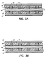
- Figures 3A and 3B are cross sections of tubular pultruded members being formed in the pultrusion apparatus of Figure 1 illustrating the position of the spacers relative to the mandrel and the heated die.
- Figure 4 is a cross sectional view of a tubular pultruded member wherein two sides of the member have spacers embedded therein.
- Figure 5 is a cross sectional view of a tubular pultruded member having a rectilinear cross section wherein all four sides of the member have spacers embedded therein.
- Figure 6 is a cross sectional representation of a substantially circular pultruded member having a series of shaped wall spacers parallel to the longitudinal axis of the pultruded member.
- Figure 7 is a cross sectional view of a spacer which is itself a pultrusion which may be used in small sections as spacers or in a continuous length such as the length of the pultrusion being made.
- a tubular pultruded member and method of making same are provided wherein the tubular pultruded member has a substantially uniform wall thickness throughout provided by a series of wall spacers embedded in the tubular pultruded member having a thickness equal to the uniform distance between the outside surface of the mandrel and the inside surface of the die.
- uniform distance it is intended to define the distance between the outside surface of the mandrel and the inside surface of the die if the mandrel and the die were precisely positioned relative to each other so that the distance therebetween along any longitudinal axis would be substantially uniform.
- tubular pultruded member having a square cross section wherein each of the four sides have substantially the same wall thickness in cross section and also along each of the four longitudinal axes of the pultruded member. It also means that a similar tubular pultruded member may have two parallel sides, for example, having the same uniform wall thickness and two perpendicular sides having the same uniform, but different, wall thicknesses. Similarly, it includes a substantially circular tubular pultruded member wherein the wall thickness through a cross section as well as along any longitudinal axis is substantially uniform.
- FIG. 1 the typical hollow pultrusion process is illustrated wherein continuous mat reinforcement 10 and roving 12 are first submerged in liquid polymer baths 14 then formed through preforming dies 16 around a mandrel 18 which extends through the forming die section and through the heated die 17.
- the pulling section 19 is illustrated as a pair of continuous caterpillar type belts 20 containing pads 21 that engage the pultrusion 23.
- the carrier tape 25 with the spacers 26 according to the present invention is typically supplied to the mandrel surface after having been pulled through a liquid polymer bath 14 and accordingly, the carrier tape with the wall spacers and the reinforcing fibers are simultaneously pulled around the mandrel and into and through the heated die to shape and cure the liquid polymer into the tubular pultruded member.
- the spacers on the top and bottom of the tubular pultruded member have a thickness equal to the uniform distance between the outside of the mandrel and the inside surface of the die.
- Figure 3A illustrates the embodiment wherein the spacers 26 extend through the carrier tape 25 while Figure 3B illustrates the spacers being in the surface of the carrier tape 25.
- the surfaces of the mandrel and die should be chosen from appropriately hard materials to resist abrasion and scratching which may arise from the sliding action of the solid spacers against the die and mandrel surfaces.
- the polymer matrix 11 includes any mat reinforcement 10 and roving 12 as shown in Figure 1. As may be observed in Figure 3A the polymer matrix 11 is between the inside of the heated die 17 and the carrier tape 25 and in Figure 3B the polymer matrix 11 extends between the carrier tape 25 which is in contact with the mandrel 18 to the inside of the heated die 17.
- the roving or tow which is similar to a yarn, provides a continuous fiber reinforcement, which is aligned axially along the longitudinal axis of the tubular pultruded member.
- the rovings are fiberglass, but they may be of other fibers as well such as carbon, aromatic polyamide fibers such as KevlarTM or any fiber that can be used as a reinforcing component.
- the mat reinforcement which may be woven or nonwoven,provides fibers which are both axially and nonaxially oriented in a thin layer and enhances transaxial mechanical properties as well as improves surface properties by way of enhancing abrasion resistance, weather resistance, etc.
- the mat reinforcement may be selected from virtually any suitable fibrous material that is capable of withstanding the temperatures required in the pultrusion process.
- they are fiberglass, polyester, nylon, propylene, polyimide and the like.
- the fiber loading including all rovings and mats is from about 50% to about 90% by weight of the total of the polymer matrix and fiber.
- the carrier tape with wall spacers according to the present invention may be used to replace the reinforcement mat or alternatively be in addition to it.
- any suitable polymer matrix may be employed in the practice of the present invention.
- the polymer may be insulating or conducting. If cross directional electrical connection is desired along the edges of the pultrusion a conducting polymer or conductive additives to the polymer may be used. Conversely, if insulating properties are desired along the edges of the pultrusion an insulating polymer may be used, or insulating fibers can be used in the outer periphery of the pultruded configuration and conducting fibers can be configured to reside away from the edges.
- the polymer is selected from the group of structural thermoplastic and thermosetting resins.
- Polyesters, epoxies, vinyl esters, polyetheretherketones, polyetherimides, polyethersulphones, high density polyethylenes, polycarbonates, acrylonitrile-butadiene-styrenes (ABS), polypropylene and nylon are in general, suitable materials with the thermosetting polyesters being preferred due to their short cure time, relative chemical inertness and low cost.
- a silicone, fluorosilicone or polyurethane elastomer may be chosen for the polymer matrix.
- Typical specific materials include Hetron 613, Arpol 7030 and 7362 available from Oshland Oil, Inc., Dion Iso 6315 available from Koppers Company, Inc. and Silmar S-7956 available from Vestron Corporation.
- Other materials may be added to the polymer bath to provide improved properties such as weather corrosion or flame resistance as desired.
- the polymer bath may contain fillers such as calcium carbonate, alumina, silica or pigments to provide a certain color or lubricants to reduce friction, for example, in sliding members. Further additives to alter the viscosity or surface tension, or to assist in bonding the pultrusion to the other materials, may be added.
- a compatible polymer should be selected. For example, if an epoxy resin is being used, it would be appropriate to add an epoxy sizing to the fiber to promote adhesion.
- the carrier tape with the wall spacer may take various forms depending upon the cross section of the tubular pultruded member. To function properly, however, in providing a substantially uniform wall thickness both the tape and the wall spacers should be capable of withstanding the temperatures involved in the pultrusion process.
- the spacers may be on the one surface of the carrier tape or alternatively extend through the tape.
- the carrier tape and spacers may be in the form of a wire frame or wire bead chain to provide the desired spacing between the outside of the mandrel and the inside of the die.
- the carrier tape and spacers can be made of materials selected to provide desirable properties in the pultruded member and accordingly, may be selected for their conductivity or insulating properties.
- polyesters such as MylarTM and other high temperature plastic materials may be used to provide the carrier tape and spacers. If insulating properties are desired a polyester carrier tape with polyester wall spacers uniformly spaced apart in the direction of the longitudinal axis may be used. Alternatively, if electrically conductive properties are desired, thin metal foil with metal spacers such as aluminum or steel may be used.
- Metal carrier tapes can provide electrical connectivity for grounds and power and/or signal voltages.
- a solid pultrusion such as that illustrated in cross section in Figure 7 may be used as both the carrier tape and the spacer. Since this pultrusion is solid and not hollow, it is noted that the tolerance and wall thickness is much higher being controlled by the tool dimension to less than 4% deviation.
- prepunched reinforcement mats may be used or if the spacer is a very hard solid such as steel may it allow the thickness of the mat to compress and poke itself through the mat.
- a mat hole punching assembly may be placed ahead of the mat polymer bath.
- FIGs 4, 5 and 6 three alternative cross sections of tubular pultruded members are illustrated wherein a substantially uniform wall thickness has been achieved according to the practice of the present invention.
- a tubular pultruded member having a rectilinear cross section is illustrated wherein carrier tapes with spacers have been incorporated or embedded in two contiguous sides of the rectangle which has been pulled through the pultrusion apparatus in the orientation illustrated thereby providing uniform spacing between the mandrel and the heated die on the two bottom surfaces and insuring substantially uniform wall thickness throughout.
- the rectilinear cross section is illustrated wherein carrier tape together with the spacers on it has been supplied during the pultrusion process to all four sides of the mandrel.
- Figure 6 represents a generally circular hollow pultrusion wherein a carrier tape with spacers shaped according to the shape of the tubular pultruded member are provided that extend in a substantial arc along the bottom of the pultruded member as it emerges from the pultrusion die and mandrel apparatus.
- This is a geometry wherein only one carrier tape may be needed to provide a tubular hollow pultruded member having substantially uniform wall thickness.
- a process for producing a tubular pultruded member having a substantially uniform wall thickness has been provided as well as the pultruded member itself.
- the tolerances in the wall thickness are much greater than in previous pultrusion processes and indeed come very close to those that may be achieved in injection molding or extrusion of tubular parts.
- By providing a high tolerance tubular member the need for final machining to get such a tolerance is avoided. This is particularly important in as much as fiberglass, a principal material used in both rovings and reinforcement mats in pultruded member, is not easy to machine or drill.
Landscapes
- Chemical & Material Sciences (AREA)
- Engineering & Computer Science (AREA)
- Composite Materials (AREA)
- Mechanical Engineering (AREA)
- Moulding By Coating Moulds (AREA)
Description
- The present invention relates generally to pultruded members and in particular to tubular pultruded members having uniform wall thickness as well as methods of making such tubular pultruded members.
- The pultrusion process generally consists of pulling continuous lines of fibers through a resin bath or impregnator and then into a preforming fixture where the section is partially shaped and excess resin and/or air are removed and then into heated dies where the section is cured continuously. Typically, the process is used to make fiber glass reinforced pultruded shapes. For a detailed discussion of pultrusion technology, reference is directed to "Handbook of Pultrusion Technology" by Raymond W. Meyer, first published 1985 by Chapman & Hall, New York. In the pultrusion process the fibers are submersed in a polymer bath and drawn through a die opening of suitable shape and high temperature to produce a solid piece of dimensions and shapes of the die which can be cut, shaped and machined. Typically, holes, slots, ridges, grooves, contact areas or screw threads may be formed in the pultruded composite member by conventional machining techniques. Alternatively, the pultrusion process maybe modified such that when the pultrusion is initially removed from the die it is pliable and can be bent or otherwise shaped to a form which upon further curing becomes a rigid structural member. Further, if the resin is a thermoplastic the process can be adjusted such that the part is removed hot from the die, shaped and then cooled to solidify or subsequently heated, formed and then cooled.
- In making tubular or hollow pultruded members a mandrel is installed to span from ahead of the polymer bath through the forming die section in the heated die and often totally through the heated die itself. The internal hole feature of the tubular pultruded member is created by a cantilevered mandrel of the desired internal shape supported only at the rear portion of the pultrusion machine. As a result, the cantilevered mandrel floats relative to the heated die and due to its length and weight which is unsupported provides variations in wall thickness of the final pultruded member. In addition, since the rovings and mat reinforcement used in the pultrusion manufacturing process may in themselves vary by up to ± 15% in thickness a further thickness variable in the final pultruded member can be created. Accordingly, the tolerances in the pultrusion process are much greater than those from injection molding processes and are typically of the order of ± 20% on wall thicknesses for major dimensions less than 50mm (two inches). Document US-A-5092950 shows such a process as defined in the preamble of claim 5 as well as the product obtained cf. the preamble of claim 1.
- By comparison, injection molding parts may have a ± 2%, or even ± 0.5% tolerance in thickness. As a result it is difficult if not impossible to use together or interchangeably structural tubular parts made from both an injection molding process and a pultrusion process.
- One technique that has previously been used to minimize these difficulties in obtaining uniform wall thickness is to have the pultrusion process run as a vertical process wherein the mandrel is centered more by gravity within the center of the heated die. However, this is a very expensive process, particularly in that it requires an extremely tall building to accommodate the larger pultruded members.
- It is an object of the present invention to provide a process for producing tubular pultruded members having substantially uniform wall thicknesses and to the resultant, tubular pultruded members.
- According to the present invention, there is provided a tubular pultruded member having a longitudinal axis comprising a plurality of reinforcing fibers in a solid polymer matrix defining a wall of said tubular member, said wall having embedded therein a series of wall spacers parallel to said longitudinal axis, each of said wall spacers having a thickness dimension equal to the thickness of the wall in which it is embedded.
- The invention also provides a method of making a tubular pultruded member having a longitudinal axis and a substantially uniform wall thickness throughout comprising providing a heated die with a mandrel extending through the forming die section, and a bath of liquid polymer, simultaneously pulling continuous reinforcing fibers and at least one carrier tape with wall spacers therein or thereon through the liquid polymer bath around said mandrel and into and through said heated die to shape and cure said liquid polymer into said tubular pultruded member, said wall spacers having a thickness equal to the uniform distance between the outside surface of the mandrel and the inside surface of the die.
- Thus, the present invention providies solid spacers in the wall of the tubular pultruded member which possess the dimensions of the walls to control the wall thickness.
- The wall spacers are used to control the wall thickness of the tubular pultruded member and are oriented in the polymer matrix in a direction substantially parallel to the longitudinal axis of the pultruded member.
- In a further embodiment of the present invention the tubular pultruded member has a substantially rectangular cross section and at least two sides thereof have wall spacers embedded therein and parallel to the longitudinal axis of the pultruded member.
- In a further embodiment of the present invention the pultruded member is a substantially rectangular cross section and all four sides thereof have wall spacers embedded therein and parallel to the longitudinal axis of the pultruded member.
- In a further embodiment of the present invention the pultruded member has a substantially circular cross section with a substantially uniform wall thickness.
- In a further embodiment of the present invention the wall spacers are uniformly spaced apart in the direction of the longitudinal axis of the pultruded member and are on or in a carrier tape. The preferred embodiments are disclosed in the dependent claims.
- The invention is illustrated with reference to the following drawings in which the dimensions of parts are not necessarily to scale but rather may be exaggerated or distorted for clarity of illustration and ease of description. In the drawings:-
- Figure 1 is an isometric representation of a typical pultrusion apparatus and process to produce a tubular pultruded member according to the present invention.
- Figure 2 is an enlarged isometric view of the die and mandrel in the pultrusion apparatus wherein two sides of the pultrusion have the wall spacers present.
- Figures 3A and 3B are cross sections of tubular pultruded members being formed in the pultrusion apparatus of Figure 1 illustrating the position of the spacers relative to the mandrel and the heated die.
- Figure 4 is a cross sectional view of a tubular pultruded member wherein two sides of the member have spacers embedded therein.
- Figure 5 is a cross sectional view of a tubular pultruded member having a rectilinear cross section wherein all four sides of the member have spacers embedded therein.
- Figure 6 is a cross sectional representation of a substantially circular pultruded member having a series of shaped wall spacers parallel to the longitudinal axis of the pultruded member.
- Figure 7 is a cross sectional view of a spacer which is itself a pultrusion which may be used in small sections as spacers or in a continuous length such as the length of the pultrusion being made.
- In accordance with the present invention a tubular pultruded member and method of making same, are provided wherein the tubular pultruded member has a substantially uniform wall thickness throughout provided by a series of wall spacers embedded in the tubular pultruded member having a thickness equal to the uniform distance between the outside surface of the mandrel and the inside surface of the die. By the term "uniform distance" it is intended to define the distance between the outside surface of the mandrel and the inside surface of the die if the mandrel and the die were precisely positioned relative to each other so that the distance therebetween along any longitudinal axis would be substantially uniform. Accordingly, it defines for example, a tubular pultruded member having a square cross section wherein each of the four sides have substantially the same wall thickness in cross section and also along each of the four longitudinal axes of the pultruded member. It also means that a similar tubular pultruded member may have two parallel sides, for example, having the same uniform wall thickness and two perpendicular sides having the same uniform, but different, wall thicknesses. Similarly, it includes a substantially circular tubular pultruded member wherein the wall thickness through a cross section as well as along any longitudinal axis is substantially uniform.
- Turning now to Figures 1 and 2 the invention will be described in greater detail. In Figure 1 the typical hollow pultrusion process is illustrated wherein
continuous mat reinforcement 10 and roving 12 are first submerged inliquid polymer baths 14 then formed through preformingdies 16 around amandrel 18 which extends through the forming die section and through theheated die 17. Thepulling section 19 is illustrated as a pair of continuouscaterpillar type belts 20 containingpads 21 that engage thepultrusion 23. The carrier tape 25 with thespacers 26 according to the present invention (see Figure 2) is typically supplied to the mandrel surface after having been pulled through aliquid polymer bath 14 and accordingly, the carrier tape with the wall spacers and the reinforcing fibers are simultaneously pulled around the mandrel and into and through the heated die to shape and cure the liquid polymer into the tubular pultruded member. As illustrated in the cross sections of Figures 3A and 3B the spacers on the top and bottom of the tubular pultruded member have a thickness equal to the uniform distance between the outside of the mandrel and the inside surface of the die. Figure 3A illustrates the embodiment wherein thespacers 26 extend through thecarrier tape 25 while Figure 3B illustrates the spacers being in the surface of thecarrier tape 25. The surfaces of the mandrel and die should be chosen from appropriately hard materials to resist abrasion and scratching which may arise from the sliding action of the solid spacers against the die and mandrel surfaces. In Figures 3A and 3B thepolymer matrix 11 includes anymat reinforcement 10 and roving 12 as shown in Figure 1. As may be observed in Figure 3A thepolymer matrix 11 is between the inside of theheated die 17 and thecarrier tape 25 and in Figure 3B thepolymer matrix 11 extends between thecarrier tape 25 which is in contact with themandrel 18 to the inside of theheated die 17. - The roving or tow, which is similar to a yarn, provides a continuous fiber reinforcement, which is aligned axially along the longitudinal axis of the tubular pultruded member. Typically, the rovings are fiberglass, but they may be of other fibers as well such as carbon, aromatic polyamide fibers such as Kevlar™ or any fiber that can be used as a reinforcing component. The mat reinforcement, which may be woven or nonwoven,provides fibers which are both axially and nonaxially oriented in a thin layer and enhances transaxial mechanical properties as well as improves surface properties by way of enhancing abrasion resistance, weather resistance, etc. As with the rovings, the mat reinforcement may be selected from virtually any suitable fibrous material that is capable of withstanding the temperatures required in the pultrusion process. Typically, they are fiberglass, polyester, nylon, propylene, polyimide and the like. Typically the fiber loading including all rovings and mats is from about 50% to about 90% by weight of the total of the polymer matrix and fiber. In certain applications, the carrier tape with wall spacers according to the present invention may be used to replace the reinforcement mat or alternatively be in addition to it.
- Any suitable polymer matrix may be employed in the practice of the present invention. The polymer may be insulating or conducting. If cross directional electrical connection is desired along the edges of the pultrusion a conducting polymer or conductive additives to the polymer may be used. Conversely, if insulating properties are desired along the edges of the pultrusion an insulating polymer may be used, or insulating fibers can be used in the outer periphery of the pultruded configuration and conducting fibers can be configured to reside away from the edges.
- Typically, the polymer is selected from the group of structural thermoplastic and thermosetting resins. Polyesters, epoxies, vinyl esters, polyetheretherketones, polyetherimides, polyethersulphones, high density polyethylenes, polycarbonates, acrylonitrile-butadiene-styrenes (ABS), polypropylene and nylon are in general, suitable materials with the thermosetting polyesters being preferred due to their short cure time, relative chemical inertness and low cost. If an elastomeric matrix is desired, a silicone, fluorosilicone or polyurethane elastomer may be chosen for the polymer matrix. Typical specific materials include Hetron 613, Arpol 7030 and 7362 available from Oshland Oil, Inc., Dion Iso 6315 available from Koppers Company, Inc. and Silmar S-7956 available from Vestron Corporation. For additional information on suitable resins attention is directed to Chapter 4 of the above-referenced Handbook by Meyer. Other materials may be added to the polymer bath to provide improved properties such as weather corrosion or flame resistance as desired. In addition, the polymer bath may contain fillers such as calcium carbonate, alumina, silica or pigments to provide a certain color or lubricants to reduce friction, for example, in sliding members. Further additives to alter the viscosity or surface tension, or to assist in bonding the pultrusion to the other materials, may be added. Naturally, if the fiber has an organic sizing applied to it, a compatible polymer should be selected. For example, if an epoxy resin is being used, it would be appropriate to add an epoxy sizing to the fiber to promote adhesion.
- The carrier tape with the wall spacer may take various forms depending upon the cross section of the tubular pultruded member. To function properly, however, in providing a substantially uniform wall thickness both the tape and the wall spacers should be capable of withstanding the temperatures involved in the pultrusion process. The spacers may be on the one surface of the carrier tape or alternatively extend through the tape. Alternatively, the carrier tape and spacers may be in the form of a wire frame or wire bead chain to provide the desired spacing between the outside of the mandrel and the inside of the die. The carrier tape and spacers can be made of materials selected to provide desirable properties in the pultruded member and accordingly, may be selected for their conductivity or insulating properties. They may be selected of the same or different material but must be able to withstand the temperature (typically 121 to 149°C (250° to 300°F)) of the pultrusion process without degrading. Ideally, they are selected to be compatible with the polymers used and bond to the polymers otherwise the carrier tape and spacers will delaminate and not provide the desired structural reinforcing properties. Typically, polyesters such as Mylar™ and other high temperature plastic materials may be used to provide the carrier tape and spacers. If insulating properties are desired a polyester carrier tape with polyester wall spacers uniformly spaced apart in the direction of the longitudinal axis may be used. Alternatively, if electrically conductive properties are desired, thin metal foil with metal spacers such as aluminum or steel may be used. Metal carrier tapes can provide electrical connectivity for grounds and power and/or signal voltages. Finally, if desired, a solid pultrusion such as that illustrated in cross section in Figure 7 may be used as both the carrier tape and the spacer. Since this pultrusion is solid and not hollow, it is noted that the tolerance and wall thickness is much higher being controlled by the tool dimension to less than 4% deviation. When using the carrier tape with spacers together with a mat reinforcement, it is preferable to provide a hole in the mat reinforcement to enable the spacer to extend through it. To this end prepunched reinforcement mats may be used or if the spacer is a very hard solid such as steel may it allow the thickness of the mat to compress and poke itself through the mat. Alternatively, of course, a mat hole punching assembly may be placed ahead of the mat polymer bath.
- Turning now to Figures 4, 5 and 6, three alternative cross sections of tubular pultruded members are illustrated wherein a substantially uniform wall thickness has been achieved according to the practice of the present invention. In Figure 4 a tubular pultruded member having a rectilinear cross section is illustrated wherein carrier tapes with spacers have been incorporated or embedded in two contiguous sides of the rectangle which has been pulled through the pultrusion apparatus in the orientation illustrated thereby providing uniform spacing between the mandrel and the heated die on the two bottom surfaces and insuring substantially uniform wall thickness throughout. In Figure 5, the rectilinear cross section is illustrated wherein carrier tape together with the spacers on it has been supplied during the pultrusion process to all four sides of the mandrel. Figure 6 represents a generally circular hollow pultrusion wherein a carrier tape with spacers shaped according to the shape of the tubular pultruded member are provided that extend in a substantial arc along the bottom of the pultruded member as it emerges from the pultrusion die and mandrel apparatus. This is a geometry wherein only one carrier tape may be needed to provide a tubular hollow pultruded member having substantially uniform wall thickness.
- Thus, according to the present invention a process for producing a tubular pultruded member having a substantially uniform wall thickness has been provided as well as the pultruded member itself. The tolerances in the wall thickness are much greater than in previous pultrusion processes and indeed come very close to those that may be achieved in injection molding or extrusion of tubular parts. By providing a high tolerance tubular member the need for final machining to get such a tolerance is avoided. This is particularly important in as much as fiberglass, a principal material used in both rovings and reinforcement mats in pultruded member, is not easy to machine or drill.
Claims (9)
- A tubular pultruded member (23) having a longitudinal axis comprising a plurality of reinforcing fibers (12) in a solid polymer matrix defining a wall of said tubular member, characterised by said wall having embedded therein a series of wall spacers (26) parallel to said longitudinal axis, each of said wall spacers (26) having a thickness dimension equal to the thickness of the wall in which it is embedded.
- The tubular pultruded member of claim 1 wherein said series of wall spacers (26) are all of the same thickness, and the wall thickness is substantially uniform throughout.
- The tubular pultruded member of claim 1 or claim 2 wherein said series of wall spacers (26) are uniformly spaced apart in the direction of said longitudinal axis.
- The tubular pultruded member of any one of claims 1 to 3 wherein said wall spacers (26) are in or on a carrier tape (25).
- The method of making a tubular pultruded member (23) having a longitudinal axis and a substantially uniform wall thickness throughout comprising providing a heated die (17) with a mandrel (18) extending through the forming die section, and a bath (14) of liquid polymer, characterised by simultaneously pulling continuous reinforcing fibers (12) and at least one carrier tape (25) with wall spacers (26) therein or thereon through the liquid polymer bath around said mandrel and into and through said heated die to shape and cure said liquid polymer into said tubular pultruded member, said wall spacers (26) having a thickness equal to the uniform distance between the outside surface of the mandrel and the inside surface of the die.
- The method of claim 5 including the step of pulling said fibers (12) and carrier tape (25) through said bath (14), around said mandrel (18) and into and through a preforming die (16) to partially shape said member before pulling it into and through said heated die (17).
- The method of claim 5 or claim 6 wherein said mandrel (18) and heated die (17) form a tubular member having a substantially rectangular cross section and including the step of pulling at least two carrier tapes (25) with wall spacers (26) corresponding to at least two sides of said substantially rectangular cross section through said polymer bath around said mandrel and through said heated die.
- The method of claim 5 or claim 6 wherein said mandrel and heated die form a tubular member having a substantially circular cross section.
- The method of any one of claims 5 to 8 wherein said wall spacers are uniformly spaced apart in the direction of said longitudinal axis.
Applications Claiming Priority (2)
| Application Number | Priority Date | Filing Date | Title |
|---|---|---|---|
| US07/993,845 US5366773A (en) | 1992-12-21 | 1992-12-21 | Tubular pultruded member having uniform wall thickness |
| US993845 | 1992-12-21 |
Publications (2)
| Publication Number | Publication Date |
|---|---|
| EP0604099A1 EP0604099A1 (en) | 1994-06-29 |
| EP0604099B1 true EP0604099B1 (en) | 1997-03-19 |
Family
ID=25539994
Family Applications (1)
| Application Number | Title | Priority Date | Filing Date |
|---|---|---|---|
| EP93310054A Expired - Lifetime EP0604099B1 (en) | 1992-12-21 | 1993-12-14 | Tubular pultruded member having uniform wall thickness |
Country Status (3)
| Country | Link |
|---|---|
| US (1) | US5366773A (en) |
| EP (1) | EP0604099B1 (en) |
| JP (1) | JPH0811425B2 (en) |
Families Citing this family (18)
| Publication number | Priority date | Publication date | Assignee | Title |
|---|---|---|---|---|
| US5549947A (en) * | 1994-01-07 | 1996-08-27 | Composite Development Corporation | Composite shaft structure and manufacture |
| US5653923A (en) * | 1996-02-29 | 1997-08-05 | Owens-Corning Fiberglas Technology, Inc. | Method for making shaped members using a foam froth |
| US5948472A (en) * | 1996-09-10 | 1999-09-07 | Lawrie Technology, Inc. | Method for making a pultruded product |
| DE19641946A1 (en) * | 1996-10-11 | 1998-04-16 | Huels Chemische Werke Ag | Multi-layer plastic pipe with segmented barrier layer |
| US6972144B2 (en) * | 2002-04-19 | 2005-12-06 | Hunter Paine Enterprises, Llc | Composite structural material and method of making same |
| WO2004101909A1 (en) * | 2003-05-14 | 2004-11-25 | N.V. Bekaert S.A. | Pultruded composite profile reinforced by metal cords |
| US20050031840A1 (en) * | 2003-08-05 | 2005-02-10 | Xerox Corporation | RF connector |
| US7052763B2 (en) * | 2003-08-05 | 2006-05-30 | Xerox Corporation | Multi-element connector |
| TW200635830A (en) * | 2004-12-29 | 2006-10-16 | Hunter Paine Entpr Llc | Composite structural material and method of making the same |
| WO2007009214A1 (en) * | 2005-07-15 | 2007-01-25 | Mastercore System Ltd. | Multistage method and apparatus for continuously forming a composite article |
| JP5608642B2 (en) * | 2008-05-13 | 2014-10-15 | ストライカー・スピン | Composite spinal rod |
| US9408649B2 (en) | 2008-09-11 | 2016-08-09 | Innovasis, Inc. | Radiolucent screw with radiopaque marker |
| US9433439B2 (en) | 2009-09-10 | 2016-09-06 | Innovasis, Inc. | Radiolucent stabilizing rod with radiopaque marker |
| US8721850B2 (en) * | 2010-02-02 | 2014-05-13 | Roche Diagnostics Operations, Inc. | Biosensor and methods for manufacturing |
| US20130092316A1 (en) * | 2011-10-14 | 2013-04-18 | Rahul Pakal | Reinforced Liners For Pipelines |
| US9267635B2 (en) | 2013-03-11 | 2016-02-23 | Exxonmobil Upstream Research Company | Pipeline liner monitoring system |
| US20150195897A1 (en) | 2014-01-08 | 2015-07-09 | Joseph A. Swift | Apparatus having management of electrical power capacity regions and management of thermal capacity regions |
| EP3569392B1 (en) * | 2018-05-17 | 2021-07-07 | Siemens Gamesa Renewable Energy A/S | Pultrusion method and apparatus |
Family Cites Families (9)
| Publication number | Priority date | Publication date | Assignee | Title |
|---|---|---|---|---|
| US2751320A (en) * | 1953-02-16 | 1956-06-19 | Taylor Fibre Co | Method of continuous production of rods, tubes, and the like |
| US3470051A (en) * | 1965-08-05 | 1969-09-30 | Leonard S Meyer | Formation of reinforced plastic rods and tubes |
| JPS4869870A (en) * | 1971-12-25 | 1973-09-21 | ||
| DE2910984A1 (en) * | 1979-03-21 | 1980-10-09 | Bayer Ag | FIBER COMPOSITE PARTS WITH INSERTS AND METHOD FOR THEIR PRODUCTION |
| JPH03143622A (en) * | 1989-10-31 | 1991-06-19 | Sekisui Chem Co Ltd | Wire-net-inserted reinforced plastic draw molded product |
| FI85403C (en) * | 1989-12-22 | 1992-04-10 | Neste Oy | Process for producing a plastic composite beam or pillar with the steel reinforcement |
| GB9008655D0 (en) * | 1990-04-18 | 1990-06-13 | Caledonia Composites | Vertical pultruder |
| US5092950A (en) * | 1990-08-06 | 1992-03-03 | Phillips Petroleum Company | Molding method using a mandrel stabilizer |
| JPH04301436A (en) * | 1991-03-29 | 1992-10-26 | Sekisui Chem Co Ltd | Method for molding fiber-reinforced synthetic resin composite |
-
1992
- 1992-12-21 US US07/993,845 patent/US5366773A/en not_active Expired - Lifetime
-
1993
- 1993-12-14 EP EP93310054A patent/EP0604099B1/en not_active Expired - Lifetime
- 1993-12-20 JP JP5320100A patent/JPH0811425B2/en not_active Expired - Fee Related
Also Published As
| Publication number | Publication date |
|---|---|
| JPH0811425B2 (en) | 1996-02-07 |
| US5366773A (en) | 1994-11-22 |
| EP0604099A1 (en) | 1994-06-29 |
| JPH06218823A (en) | 1994-08-09 |
Similar Documents
| Publication | Publication Date | Title |
|---|---|---|
| US5492743A (en) | Pultruded member with functional features | |
| US5366773A (en) | Tubular pultruded member having uniform wall thickness | |
| US12145330B2 (en) | Pultruded articles and methods for making same | |
| US11248096B2 (en) | Composites with thermoplastic epoxy polymeric phase, articles such as carriers made therewith and associated methods | |
| US4200605A (en) | Production of reinforced plastic pipes | |
| KR890005310A (en) | Fiber-reinforced composite resin molded product and its manufacturing method | |
| EP0747205A3 (en) | Fiber reinforced thermoplastic structural member | |
| US5158806A (en) | Method and apparatus for manufacturing fibre-reinforcing material | |
| HU213662B (en) | Method for producing of combined plastic tube | |
| WO1995025000A1 (en) | A process of melt impregnation | |
| DE3718676C2 (en) | ||
| KR20110020241A (en) | Lightweight, highly rigid composite with class A surface treatment | |
| US5567505A (en) | Means and method of applying a plastic finishing layer to the surface of a composite article; coated composite article | |
| EP0438745A1 (en) | Flexible corrosion-resistant conduit and method | |
| EP0381889B1 (en) | Laminate flexible strip and method for making same | |
| RU2009037C1 (en) | Method for manufacturing long length articles made of polymer compositions | |
| EP0549728B1 (en) | Plastics article provided with electrostatically applied coating | |
| WO2004051675A1 (en) | Three-dimensional moulded planar cable, method for production and use thereof | |
| EP0233521B1 (en) | Plane corrosion resistant apparatus parts | |
| JP3048337B2 (en) | Method for producing continuous fiber reinforced extruded plastic composite | |
| GB2101171A (en) | Gutter section | |
| KR100255003B1 (en) | Continuous fiber-reinforced extruded plastic and its manufacturing method | |
| RU2738062C1 (en) | Thermoplastic pultrusion reinforcement insert in a hollow plastic frame of a window or door unit | |
| DE10315747A1 (en) | Three-dimensional flat cable, process for its production and its use | |
| JPH0232430Y2 (en) |
Legal Events
| Date | Code | Title | Description |
|---|---|---|---|
| PUAI | Public reference made under article 153(3) epc to a published international application that has entered the european phase |
Free format text: ORIGINAL CODE: 0009012 |
|
| AK | Designated contracting states |
Kind code of ref document: A1 Designated state(s): GB |
|
| 17P | Request for examination filed |
Effective date: 19941229 |
|
| 17Q | First examination report despatched |
Effective date: 19950816 |
|
| GRAG | Despatch of communication of intention to grant |
Free format text: ORIGINAL CODE: EPIDOS AGRA |
|
| GRAH | Despatch of communication of intention to grant a patent |
Free format text: ORIGINAL CODE: EPIDOS IGRA |
|
| RBV | Designated contracting states (corrected) |
Designated state(s): GB |
|
| REG | Reference to a national code |
Ref country code: DE Ref legal event code: 8566 |
|
| GRAH | Despatch of communication of intention to grant a patent |
Free format text: ORIGINAL CODE: EPIDOS IGRA |
|
| GRAH | Despatch of communication of intention to grant a patent |
Free format text: ORIGINAL CODE: EPIDOS IGRA |
|
| GRAA | (expected) grant |
Free format text: ORIGINAL CODE: 0009210 |
|
| AK | Designated contracting states |
Kind code of ref document: B1 Designated state(s): GB |
|
| PLBE | No opposition filed within time limit |
Free format text: ORIGINAL CODE: 0009261 |
|
| STAA | Information on the status of an ep patent application or granted ep patent |
Free format text: STATUS: NO OPPOSITION FILED WITHIN TIME LIMIT |
|
| 26N | No opposition filed | ||
| REG | Reference to a national code |
Ref country code: GB Ref legal event code: IF02 |
|
| PGFP | Annual fee paid to national office [announced via postgrant information from national office to epo] |
Ref country code: GB Payment date: 20101208 Year of fee payment: 18 |
|
| GBPC | Gb: european patent ceased through non-payment of renewal fee |
Effective date: 20111214 |
|
| PG25 | Lapsed in a contracting state [announced via postgrant information from national office to epo] |
Ref country code: GB Free format text: LAPSE BECAUSE OF NON-PAYMENT OF DUE FEES Effective date: 20111214 |