EP0602365B1 - Assembly for a north-south automatice transaxle - Google Patents
Assembly for a north-south automatice transaxle Download PDFInfo
- Publication number
- EP0602365B1 EP0602365B1 EP93117754A EP93117754A EP0602365B1 EP 0602365 B1 EP0602365 B1 EP 0602365B1 EP 93117754 A EP93117754 A EP 93117754A EP 93117754 A EP93117754 A EP 93117754A EP 0602365 B1 EP0602365 B1 EP 0602365B1
- Authority
- EP
- European Patent Office
- Prior art keywords
- passageway
- assembly
- shaft portion
- differential
- disposed
- Prior art date
- Legal status (The legal status is an assumption and is not a legal conclusion. Google has not performed a legal analysis and makes no representation as to the accuracy of the status listed.)
- Expired - Lifetime
Links
Images




Classifications
-
- F—MECHANICAL ENGINEERING; LIGHTING; HEATING; WEAPONS; BLASTING
- F16—ENGINEERING ELEMENTS AND UNITS; GENERAL MEASURES FOR PRODUCING AND MAINTAINING EFFECTIVE FUNCTIONING OF MACHINES OR INSTALLATIONS; THERMAL INSULATION IN GENERAL
- F16H—GEARING
- F16H57/00—General details of gearing
- F16H57/02—Gearboxes; Mounting gearing therein
- F16H57/021—Shaft support structures, e.g. partition walls, bearing eyes, casing walls or covers with bearings
- F16H57/022—Adjustment of gear shafts or bearings
-
- B—PERFORMING OPERATIONS; TRANSPORTING
- B60—VEHICLES IN GENERAL
- B60K—ARRANGEMENT OR MOUNTING OF PROPULSION UNITS OR OF TRANSMISSIONS IN VEHICLES; ARRANGEMENT OR MOUNTING OF PLURAL DIVERSE PRIME-MOVERS IN VEHICLES; AUXILIARY DRIVES FOR VEHICLES; INSTRUMENTATION OR DASHBOARDS FOR VEHICLES; ARRANGEMENTS IN CONNECTION WITH COOLING, AIR INTAKE, GAS EXHAUST OR FUEL SUPPLY OF PROPULSION UNITS IN VEHICLES
- B60K17/00—Arrangement or mounting of transmissions in vehicles
- B60K17/04—Arrangement or mounting of transmissions in vehicles characterised by arrangement, location or kind of gearing
- B60K17/16—Arrangement or mounting of transmissions in vehicles characterised by arrangement, location or kind of gearing of differential gearing
-
- F—MECHANICAL ENGINEERING; LIGHTING; HEATING; WEAPONS; BLASTING
- F16—ENGINEERING ELEMENTS AND UNITS; GENERAL MEASURES FOR PRODUCING AND MAINTAINING EFFECTIVE FUNCTIONING OF MACHINES OR INSTALLATIONS; THERMAL INSULATION IN GENERAL
- F16H—GEARING
- F16H57/00—General details of gearing
- F16H57/02—Gearboxes; Mounting gearing therein
- F16H57/023—Mounting or installation of gears or shafts in the gearboxes, e.g. methods or means for assembly
-
- F—MECHANICAL ENGINEERING; LIGHTING; HEATING; WEAPONS; BLASTING
- F16—ENGINEERING ELEMENTS AND UNITS; GENERAL MEASURES FOR PRODUCING AND MAINTAINING EFFECTIVE FUNCTIONING OF MACHINES OR INSTALLATIONS; THERMAL INSULATION IN GENERAL
- F16H—GEARING
- F16H57/00—General details of gearing
- F16H57/02—Gearboxes; Mounting gearing therein
- F16H57/037—Gearboxes for accommodating differential gearings
-
- B—PERFORMING OPERATIONS; TRANSPORTING
- B60—VEHICLES IN GENERAL
- B60K—ARRANGEMENT OR MOUNTING OF PROPULSION UNITS OR OF TRANSMISSIONS IN VEHICLES; ARRANGEMENT OR MOUNTING OF PLURAL DIVERSE PRIME-MOVERS IN VEHICLES; AUXILIARY DRIVES FOR VEHICLES; INSTRUMENTATION OR DASHBOARDS FOR VEHICLES; ARRANGEMENTS IN CONNECTION WITH COOLING, AIR INTAKE, GAS EXHAUST OR FUEL SUPPLY OF PROPULSION UNITS IN VEHICLES
- B60K17/00—Arrangement or mounting of transmissions in vehicles
- B60K17/04—Arrangement or mounting of transmissions in vehicles characterised by arrangement, location or kind of gearing
-
- B—PERFORMING OPERATIONS; TRANSPORTING
- B60—VEHICLES IN GENERAL
- B60K—ARRANGEMENT OR MOUNTING OF PROPULSION UNITS OR OF TRANSMISSIONS IN VEHICLES; ARRANGEMENT OR MOUNTING OF PLURAL DIVERSE PRIME-MOVERS IN VEHICLES; AUXILIARY DRIVES FOR VEHICLES; INSTRUMENTATION OR DASHBOARDS FOR VEHICLES; ARRANGEMENTS IN CONNECTION WITH COOLING, AIR INTAKE, GAS EXHAUST OR FUEL SUPPLY OF PROPULSION UNITS IN VEHICLES
- B60K17/00—Arrangement or mounting of transmissions in vehicles
- B60K17/22—Arrangement or mounting of transmissions in vehicles characterised by arrangement, location, or type of main drive shafting, e.g. cardan shaft
-
- F—MECHANICAL ENGINEERING; LIGHTING; HEATING; WEAPONS; BLASTING
- F16—ENGINEERING ELEMENTS AND UNITS; GENERAL MEASURES FOR PRODUCING AND MAINTAINING EFFECTIVE FUNCTIONING OF MACHINES OR INSTALLATIONS; THERMAL INSULATION IN GENERAL
- F16C—SHAFTS; FLEXIBLE SHAFTS; ELEMENTS OR CRANKSHAFT MECHANISMS; ROTARY BODIES OTHER THAN GEARING ELEMENTS; BEARINGS
- F16C2361/00—Apparatus or articles in engineering in general
- F16C2361/61—Toothed gear systems, e.g. support of pinion shafts
-
- F—MECHANICAL ENGINEERING; LIGHTING; HEATING; WEAPONS; BLASTING
- F16—ENGINEERING ELEMENTS AND UNITS; GENERAL MEASURES FOR PRODUCING AND MAINTAINING EFFECTIVE FUNCTIONING OF MACHINES OR INSTALLATIONS; THERMAL INSULATION IN GENERAL
- F16H—GEARING
- F16H57/00—General details of gearing
- F16H57/02—Gearboxes; Mounting gearing therein
- F16H2057/02039—Gearboxes for particular applications
- F16H2057/02043—Gearboxes for particular applications for vehicle transmissions
-
- F—MECHANICAL ENGINEERING; LIGHTING; HEATING; WEAPONS; BLASTING
- F16—ENGINEERING ELEMENTS AND UNITS; GENERAL MEASURES FOR PRODUCING AND MAINTAINING EFFECTIVE FUNCTIONING OF MACHINES OR INSTALLATIONS; THERMAL INSULATION IN GENERAL
- F16H—GEARING
- F16H57/00—General details of gearing
- F16H57/02—Gearboxes; Mounting gearing therein
- F16H2057/02039—Gearboxes for particular applications
- F16H2057/02043—Gearboxes for particular applications for vehicle transmissions
- F16H2057/02047—Automatic transmissions
-
- Y—GENERAL TAGGING OF NEW TECHNOLOGICAL DEVELOPMENTS; GENERAL TAGGING OF CROSS-SECTIONAL TECHNOLOGIES SPANNING OVER SEVERAL SECTIONS OF THE IPC; TECHNICAL SUBJECTS COVERED BY FORMER USPC CROSS-REFERENCE ART COLLECTIONS [XRACs] AND DIGESTS
- Y10—TECHNICAL SUBJECTS COVERED BY FORMER USPC
- Y10T—TECHNICAL SUBJECTS COVERED BY FORMER US CLASSIFICATION
- Y10T74/00—Machine element or mechanism
- Y10T74/19—Gearing
- Y10T74/19219—Interchangeably locked
- Y10T74/19251—Control mechanism
-
- Y—GENERAL TAGGING OF NEW TECHNOLOGICAL DEVELOPMENTS; GENERAL TAGGING OF CROSS-SECTIONAL TECHNOLOGIES SPANNING OVER SEVERAL SECTIONS OF THE IPC; TECHNICAL SUBJECTS COVERED BY FORMER USPC CROSS-REFERENCE ART COLLECTIONS [XRACs] AND DIGESTS
- Y10—TECHNICAL SUBJECTS COVERED BY FORMER USPC
- Y10T—TECHNICAL SUBJECTS COVERED BY FORMER US CLASSIFICATION
- Y10T74/00—Machine element or mechanism
- Y10T74/21—Elements
- Y10T74/2186—Gear casings
Definitions
- the present invention relates to a north-south transaxle assembly for a motor vehicle according to the preamble of claim 1.
- motor vehicles require three basic components. These components include a power plant (such as an internal combustion engine), a power train and wheels.
- a power plant such as an internal combustion engine
- the internal combustion engine produces force by the conversion of chemical energy in a liquid fuel into mechanical energy of motion (kinetic energy).
- the function of the power train is to transmit this force to the wheels to provide movement of the motor vehicle.
- the power train's main component is typically referred to as the "transaxle".
- Engine torque and speed are converted in the transaxle in accordance with the tractive-power demand of the motor vehicle.
- the transaxle is also capable of controlling the direction of rotation being applied to the wheels, so that the motor vehicle may be driven both forward and backward.
- the transaxle typically includes two basic components. These components are a transmission and differential.
- the transmission is generally referred to as a manually actuated or automatic transmission.
- An automatic transmission is designed to take automatic control of frictional units, gear ratio selection and gear shifting.
- An example of such an automatic transmission is disclosed in U.S. Patent No. 4,875,391, issued on October 24, 1989, to Leising, et al.
- the differential is typically an arrangement of gears forming an epicyclic train for connecting two shafts or axles for the wheels in the same line, dividing the force from the transmission equally between them, and permitting one shaft to revolve faster than the other.
- transaxles have been orientated in an east-west manner or generally perpendicular to a longitudinal axis of the motor vehicle. While this orientation provides several advantages, it has been desired to orientate the transaxle in a north-south manner or generally parallel to the longitudinal axis of the motor vehicle. It has also been desired to provide a north-south orientated transaxle which is more compact and meets specific needs and requirements of today's motor vehicle design.
- the present invention is characterized by the features of claim 1.
- the transaxle includes other specific features to be described and claimed in the subclaims.
- an automatic transaxle is provided for a motor vehicle having a north-south orientation generally parallel to a longitudinal axis of the motor vehicle.
- the transaxle has a transfer assembly between a transmission assembly and differential assembly.
- a retaining arrangement is provided which allows sprocket wheels and a transfer chain to be removed and installed without disturbing bearings for the transmission assembly and transfer assembly.
- the transaxle case and differential assembly are made of an aluminum material to provide thermal compensation of bearing preload for the differential assembly.
- a lubrication system is provided in the differential assembly for lubricating a bearing of the transfer assembly.
- an assembly is provided to retain the connector to the transaxle case to allow removal and installation of a solenoid assembly without disturbing the connector.
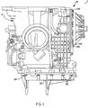
- FIG. 1 is a plan view of a north-south automatic transaxle according to the present invention.
- FIG. 2 is an elevational view of the transaxle of FIG. 1.
- FIG. 3 is an end view of the transaxle of FIGS. 1 and 2 rotated approximately one hundred eighty degrees.
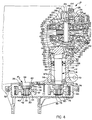
- FIG. 4 is a fragmentary view of the transaxle of FIGS. 1 and 2.
- FIG. 5 is a partial enlarged view of a portion of FIG. 4 illustrating a transfer shaft being installed.
- FIG. 6 is a view similar to FIG. 5 illustrating the transfer shaft installed.
- FIG. 7 is a view similar to FIG. 6 illustrating the transfer shaft installed and retained in the transaxle.
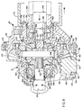
- FIG. 8 is an enlarged view of a portion of the transaxle of FIG. 4 illustrated in operational relationship with an adjustment assembly.
- FIG. 9 is an enlarged view of a portion of the transaxle of FIG. 2 with a cover member removed.
- FIG. 10 is a sectional view taken along line 10-10 of FIG. 9.
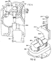
- FIG. 11 is a fragmentary view of the transaxle of FIGS. 1 and 2.
- FIG. 12 is a partial exploded perspective view of a portion of FIG. 11.
- a transaxle 10 is illustrated for a motor vehicle (not shown) such as an automotive vehicle.
- the transaxle 10 has a north-south or longitudinal powertrain orientation generally parallel to a longitudinal axis of the motor vehicle.
- the transaxle 10 includes a case 12, transmission assembly 14, transfer assembly 16 and differential assembly 18.
- the case 12 houses the transmission assembly 14, transfer assembly 16 and differential assembly 18.
- the transmission assembly 14 converts torque and speed from an engine (not shown) such as an internal combustion engine of the motor vehicle and produces a torque output.
- the transfer assembly 16 transfers the torque output from the transmission assembly 14 to the differential assembly 18.
- the differential assembly 18 divides the torque output and transmits the resultant torque to wheels (not shown) of the motor vehicle.
- the case 12 has a first passageway 20 extending longitudinally therethrough to house the transmission assembly 14.
- the case 12 also has a second passageway 22 spaced laterally and substantially parallel to the first passageway 20 and extending longitudinally therethrough to house the transfer assembly 16.
- the case 12 includes a cavity 24 at one end of the second passageway 22 to house the differential assembly 18.
- the cavity 24 is closed by a differential cover member 26 connected by suitable fastening means such as bolts 28 to a side of the case 12.
- the case 12 also includes a rear cover member 30 connected by suitable fastening means such as bolts 32 to a rear or output end of the case 12 to enclose the ends of the transmission assembly 14 and transfer assembly 16.
- the case 12, differential cover member 26 and rear cover member 30 are from a similar metal material such as an aluminum material.
- the transmission assembly 14 is an automatic transmission of the type disclosed in U.S. Patent No. 4,875,391 to Leising et al. and assigned to the same assignee at the present invention, the disclosure of which is hereby incorporated by reference.
- the transmission assembly 14 includes a shaft portion 34 of a rear carrier of a gear assembly (not shown) disposed in the first passageway 20.
- the shaft portion 34 extends longitudinally and is rotatably supported by a bearing 35 such as a tapered roller bearing in the case 12.
- the transmission assembly 14 includes a nut 36 which threadably engages a threaded portion 37 on the shaft portion 34 to retain the shaft portion 34 and bearing 35 in the case 12.
- the transmission assembly 14 also includes an output sprocket wheel 38 connected by a spline connection 39 to the shaft portion 34.
- the output sprocket wheel 38 is retained to the shaft portion 34 by suitable retaining means such as a wave washer 40 and a snap ring 42.
- the transmission assembly 14 further includes a spacer 44 disposed between the nut 36 and the output sprocket wheel 38 to align the output sprocket wheel 38 with a transfer sprocket wheel 78 to be described.
- the transfer assembly 16 includes a transfer shaft 46 disposed in the second passageway 22.
- the transfer shaft 46 has a head portion 48 and shaft portion 50.
- the head portion 48 has a generally frustoconical shape with a plurality of teeth 52 spaced circumferentially thereabout to form a pinion gear.
- the shaft portion 50 extends longitudinally from the head portion 48 and is rotatably supported in the second passageway 22 by front and rear bearings 54 and 56.
- the bearings 54, 56 are, preferably, tapered roller bearings having a cup 58 engaging the case 12 and a cone 60 with tapered rollers 62 disposed about the shaft portion 50 and engaging the cup 58.
- the cup 58 and cone 60 have tapered mating surfaces extending inwardly at an angle toward the transfer shaft 46. It should be appreciated that the front and rear bearings 54 and 56 are conventional and allow the transfer shaft 46 to rotate relative to the case 12.
- the transfer assembly 16 also includes front and rear seals 66 and 68 disposed in the second passageway 22 and about the shaft portion 50 and engaging the case 12.
- the front and rear seals 66 and 68 abut each other and are located at a predetermined position along the shaft portion 50 for a function to be described.
- the transfer assembly 16 includes a fluid baffle 72 disposed in the second passageway 22 and about the shaft portion 50 and engaging the case 12.
- the fluid baffle 72 is located adjacent the rear bearing 56 to prevent fluid entering the second passageway 22 from the rear bearing 56.
- the transfer assembly 16 further includes a nut 74 which threadably engages a threaded portion 76 on the transfer shaft 46 to retain the transfer shaft 46 and bearings 54, 56 in the case 12.
- the transfer assembly 16 also includes a transfer sprocket wheel 78 connected by a spline connection 79 to the shaft portion 50 of the transfer shaft 46.
- the transfer sprocket wheel 78 is retained to the transfer shaft 46 by suitable retaining means such as a wave washer 80 and a snap ring 82.
- the transaxle 10 also includes a transfer chain 84 disposed about the output sprocket wheel 38 and transfer sprocket wheel 78 to connect the sprocket wheels 38 and 78 together.
- the transaxle 10 further includes a snubber 85 connected to the case 12 by suitable fastening means such as bolts 86.
- the snubber 85 is made of an elastomeric material and is located on the tension or power side of the transfer chain 84. The snubber 85 dampens and resists excursions or vibrations of the transfer chain 84 due to a vertical component of rotation.
- the method includes installing the front bearing 54 in the case 12.
- the cup 58 of the front bearing 54 is pressed or seated along the second passageway 22 in the case 12.
- the cone 60 of the front bearing 54 is disposed on the cup 58.
- a tool such as a dial indicator (not shown), is used to measure the depth of the transfer shaft 46 and determine the thickness of a shim 87a (FIG. 4) that will be required between the head portion 48 and the bearing cone 60.
- the shim 87 is disposed about the shaft portion 50 and seated against the head portion 48.
- the cone 60 is removed from the case 12, disposed about the shaft portion 50, and pressed or seated against the head portion 48.
- the method includes installing the transfer shaft 46 with shim 87 and cone 60 in the case 12.
- the shaft portion 50 is inserted into the cavity 24 and rotated to enter the second passageway 22.
- the shaft portion 50 is extended through the second passageway 22 until the cone 60 seats against the cup 58 of the front bearing 54.
- the method includes installing the front and rear seals 66 and 68 and fluid baffle 72 in the case 12.
- the front and rear seals 66 and 68 are disposed about the shaft portion 50.
- a tool such as a press (not shown), is used to install the front and rear seals 66 and 68 at the proper location along the shaft portion 50.
- the fluid baffle 72 is disposed about the shaft portion 50 and installed in the case 12 at the proper location along the shaft portion 50.
- the method includes installing the rear bearing 56 in the case 12.
- the cup 58 of the rear bearing 56 is pressed or seated along the second passageway 22 in the case 12.
- a preload shim 87b is disposed about the shaft portion 50 and seated against a shoulder of the shaft portion 50.
- the cone 60 is disposed about the shaft portion 50 and pressed onto the shaft portion 50 until seated against the cup 58 and preload shim 87b.
- the nut 74 is threaded onto the threaded portion 76 and tightened to obtain a predetermined torque. After the predetermined torque is obtained, the nut 74 is staked to the transfer shaft 46.
- the method includes installing the sprocket wheels 38, 78 and transfer chain 84.
- the transfer chain 84 is disposed about the sprocket wheels 38, 78 and a chain spreader (not shown) is disposed between the sprocket wheels 38, 78 and adjusted to apply pressure to the transfer chain 84 and form an assembly.
- the sprocket wheels 38, 78 are then slip fitted onto the shaft portions 34, 50, respectively.
- the chain spreader is adjusted to release the pressure on the transfer chain 84 and is removed.
- the wave washers 40, 80 and snap rings 42, 82 are disposed about the shaft portions 34, 50, respectively.
- the chain snubber 85 is then installed with the bolts 86.
- the rear cover member 30 is installed with bolts 32. It should be appreciated that the spacer 44 may be replaced with a different thickness to ensure that the sprocket wheels 38, 78 are at the same height prior to installing the sprocket wheels 38, 78 and transfer chain 84.
- the differential assembly 18 includes a ring or hypoid gear 88 disposed in the cavity 24 and having a plurality of teeth 90 engaging the teeth 52 of the transfer shaft 46.
- the differential assembly 18 also includes a differential case assembly, generally indicated at 92, disposed in the cavity 24 and connected to the hypoid gear 88 by suitable fastening means such as bolts 94.
- the differential assembly 18 further includes inner and outer stub or axle shafts 96 and 98 extending into the cavity 24 and differential case assembly 92.
- the inner stub shaft 96 extends laterally or perpendicularly to the longitudinal axis of the transaxle 10 and is rotatably supported by bearings (not shown) in the case 12.
- the outer stub shaft 98 is shorter in length than the inner stub shaft 96.
- the outer stub shaft 98 is aligned with inner stub shaft 96 and extends laterally or perpendicularly to the longitudinal axis of the transaxle 10. It should be appreciated that the stub shafts 96, 98 are operatively connected to the wheels of the motor vehicle.
- the differential assembly 18 includes inner and outer differential adjusters 100 and 102 disposed about the inner and outer stub shafts 96 and 98, respectively, and engaging the case 12.
- the differential adjusters 100, 102 are generally annular and made of a metal material such as an aluminum material similar to the differential cover member 26.
- the differential adjusters 100, 102 have a threaded portion 104 which threadably engages corresponding threaded portions 106 on the case 12 to allow rotation and lateral adjustment of the differential adjusters 100, 102 relative to the case 12.
- the differential assembly 18 includes inner and outer adjuster lock brackets 108 and 110 connected to the case 12 by suitable fastening means such as bolts 112 and which engage the differential adjusters 100, 102 to prevent rotation of the differential adjusters 100, 102.
- the differential assembly 18 further includes inner and outer seals 114, 116 disposed between the differential adjusters 100, 102 and stub shafts 96, 98 to prevent fluid from exiting the differential assembly 18.
- the differential assembly 18 also includes inner and outer bearings 118 and 120 disposed between the differential adjusters 100, 102 and differential case assembly 92 to rotatably support the differential case assembly 92 in the cavity 24.
- the bearings 118, 120 are, preferably, tapered roller bearings having a cup 122 engaging the differential adjusters 100, 102 and a cone 124 with tapered rollers 126 disposed about the differential case assembly 92 and engaging the cup 122. It should be appreciated that the bearings 118, 120 are conventional and allow the differential case assembly 92 to rotate relative to the differential adjusters 100, 102 and case 12.
- the differential case assembly 92 includes inner and outer differential carriers 128 and 130 which form a central cavity 132 therein with inner and outer apertures 134 and 136 at each end.
- the stub shafts 96, 98 extend through the apertures 134, 136 and into the central cavity 132.
- the differential carriers 128, 130 are made of a metal material such as a cast iron or aluminum material.
- the differential case assembly 92 also includes a pinion shaft 138 disposed in a longitudinal aperture 140 extending through the inner differential carrier 128.
- the pinion shaft 138 is secured to the inner differential carrier 128 by suitable means such as a pin 144.
- the differential case assembly 92 further includes front and rear pinion gears 146 and 148 disposed in the central cavity 132 and about the pinion shaft 138.
- the front and rear pinion gears 146 and 148 have a generally frustoconical shape with a plurality of teeth 150 and 152, respectively, spaced circumferentially thereabout.
- the differential case assembly 92 also includes bearing pads 154 disposed between the pinion gears 146, 148 and the inner differential carrier 128. It should be appreciated that the pinion gears 146, 148 may rotate about the pinion shaft 138.
- the differential case assembly 92 also includes inner and outer side gears 156 and 158 disposed in the central cavity 132.
- the inner and outer side gears 156 and 158 are connected by a spline connection to the inner and outer stub shafts 96 and 98, respectively, and may be retained by suitable retaining means such as a "C" shaped clip 160.
- the inner and outer side gears 156 and 158 have a generally frustoconical shape with a plurality of teeth 162 and 164, respectively, engaging the teeth 150 and 152 of the front and rear pinion gears 146 and 148.
- the differential case assembly 92 includes bearing pads 166 disposed between the side gears 156, 158 and carriers 128, 130.
- hypoid gear 88 drives the differential case assembly 92 for all gears and provides input power to the stub shafts 96, 98. It should also be appreciated that the pinion gears 146, 148 and side gears 156, 158 allow the stub shafts 96, 98 to rotate at different speeds while the motor vehicle is moving.
- the method includes preloading the bearings 118, 120 and differential cover member 26 of the transaxle 10.
- the preloading is performed at room temperature and since the case 12, differential cover member 26, adjusters 100, 102 and differential carriers 128, 130 are made of aluminum material, thermal compensation is provided to equalize bearing preload over a temperature operating range.
- a preload or dead weight 170 having a hook portion 172 engages corresponding slots 174 in the differential cover member 26.
- a first ram pulls the dead weight 170 in the direction indicated by the arrow and a second ram 176 pushes on the outer differential adjuster 102 to stretch the differential cover member 26.
- distance sensors are placed on the differential cover member 26 to record the stretch and an additional sensor (not shown) is placed on the inner stub shaft 96 to measure preload and backlash.
- the method includes determining the amount of backlash or engagement between the teeth 52 of the transfer shaft 46 and the teeth 90 of the hypoid gear 88.
- the amount of stretch of the differential cover member 26 is compared to predetermined plots of stretch versus preload (i.e., dead weight).
- predetermined plots of stretch versus preload i.e., dead weight.
- backlash is adjusted by rotating the differential adjusters 100, 102 and moving the differential adjustors 100, 102 laterally in tandem, in turn moving the cups 122, to achieve the target preload.
- the inner and outer adjusters 100 and 102 are rotated to move the hypoid gear 88 closer to or further away from the head portion 48 of the transfer shaft 46 by corresponding tools 178 and 180, respectively, such as a racket with spaced teeth which engage spaced recesses in the differential adjusters 100, 102. It should also be appreciated that the differential adjusters 100, 102 are unlocked before adjustment and locked in place after adjustment by the adjuster lock brackets 108, 110. It should further be appreciated that once the adjusters 100, 102 are locked in place, the dead weight 170, rams 176 and sensors are removed.
- the transaxle 10 includes a lubrication system, generally indicated at 182, in the differential assembly 18 for lubricating the front bearing 54 of the transfer assembly 14.
- the lubrication system 182 includes differential fluid in the cavity 24 which acts as a sump and is separate from the transmission assembly 14.
- the lubrication system 182 includes a fluid passageway 184 in the case 12 between the cavity 24 and an inlet aperture 186 along the second passageway 22.
- the front and rear seals 66 and 68 are located past the inlet aperture 186 to separate the differential fluid from transmission fluid of the transaxle 12. It should be appreciated that the seals 66, 68 may have a weep hole 187 between them for fluid identification purposes during leakage.
- the hypoid gear 88 rotates to act as a pump to move differential fluid in the fluid passageway 184 as indicated by the arrows.
- the differential fluid moves along the fluid passageway 184 and into the inlet aperture 186. From the inlet aperture 186, the differential fluid enters the second passageway 22 and flows between the tapered rollers 162 and through the front bearing 54. Then, the differential fluid travels between the teeth 52 in the transfer shaft 46 and the teeth 90 in the hypoid gear 88 in the cavity 24.
- the connector assembly 188 includes a connector 192 connected to a source of electrical power (not shown).
- the connector 192 has a head portion 194, a flange portion 196, and a body portion 198.
- the head portion 194 is generally rectangular in shape and has a recess 200 extending inwardly from one side for a function to be described.
- the flange portion 196 extends laterally from the head portion 194 and has a seal 197 on one side.
- the body portion 198 is generally rectangular and extends longitudinally from the flange portion 198.
- the body portion 198 extends through an aperture 202 in the case 12 and the seal 197 on the flange portion 196 engages the case 12 adjacent the aperture 202, as illustrated in FIG. 11. It should be appreciated that the aperture 202 is orientated at an angle relative to a longitudinal axis of the case 12. It should also be appreciated that the flange portion 196 has a width and length greater than the aperture 202. It should further be appreciated that the free end of the connector 192 is disposed in a correspondingly shaped cavity (not shown) of a receiver 204 of the solenoid assembly 190.
- the connector assembly 188 also includes a retainer bracket 206 for cooperating with the connector 192.
- the retainer bracket 206 is generally an inverted “L” shape and has an aperture 208 extending therethrough.
- the retainer bracket 206 has a projection 210 extending laterally from an upper end of the inverted “L” shape.
- the projection 210 is generally triangular in shape and engages the recess 200 in the connector 192.
- the connector assembly 188 further includes fastener 212 such as bolt to retain the retainer bracket 206 to the case 12.
- the fastener 212 has a head portion 214 and a shaft portion 216 extending from the head portion 216.
- the shaft portion 216 has a threaded portion 218 which threadably engages a threaded aperture 220 in the case 12 adjacent the aperture 202.
- the connector 192 is disposed in the aperture 202 such that the body portion 198 extends therethrough and the flange portion 196 abuts the case 12.
- the projection 210 of the retainer bracket 206 is disposed in the recess 200 of the head portion 194 and the aperture 208 is aligned with the aperture 220 in the case 12.
- the fastener 212 is disposed in the aperture 208 such that the shaft portion 216 extends therethrough and the threaded portion 218 engages the threaded aperture 220.
- the fastener 212 is tightened by rotating the head 214 to sandwich the connector 192 between the retainer bracket 206 and case 12.
- the solenoid assembly 190 is secured to a valve body (not shown) which is fastened to the case 12.
- the valve body is moved toward the case 12 such that the body portion 198 is disposed in the receiver 204.
- the valve body is secured to the case 12 by suitable means such as fasteners (not shown). It should be appreciated that the valve body and solenoid assembly 190 may be removed and installed without disturbing the connector 192 which is retained to the case 12 by the retainer bracket 206 and fastener 212.
- the transaxle 10 is an automatic transaxle having a north-south powertrain orientation.
- the transaxle 10 has a transfer assembly 16 between a transmission assembly 14 and differential assembly 18.
- a transfer shaft 46 of the transfer assembly 16 is installed through a differential cavity 24 and into a passageway 22.
- the transmission assembly 14 and transfer assembly 16 have corresponding nuts 36 and 74 for retaining the shafts and bearings which allow sprocket wheels 38, 78 to be installed and serviced without disturbing any bearing setting.
- the transaxle 10 uses an aluminum material for the case 12, differential cover member 26, differential adjusters 100, 102, and differential carriers 128, 130 to provide thermal compensation to equalize bearing preload over an operating range of the bearings for the differential assembly 18.
- the transaxle 10 has a unique method for adjusting the backlash between the hypoid gear 88 and transfer shaft 46.
- the transaxle 10 has a pump and lubrication system for delivery of differential fluid to the front bearing 54 for the transfer shaft 46.
- the transaxle 10 has a connector assembly 188 for retaining a connector 192 to the case 12 which allows removal and installation of a solenoid assembly 190 without disturbing the connector 192.
Landscapes
- Engineering & Computer Science (AREA)
- General Engineering & Computer Science (AREA)
- Mechanical Engineering (AREA)
- Chemical & Material Sciences (AREA)
- Combustion & Propulsion (AREA)
- Transportation (AREA)
- General Details Of Gearings (AREA)
- Structure Of Transmissions (AREA)
- Arrangement And Driving Of Transmission Devices (AREA)
- Vending Machines For Individual Products (AREA)
- Ultra Sonic Daignosis Equipment (AREA)
- Toys (AREA)
Abstract
Description
- The present invention relates to a north-south transaxle assembly for a motor vehicle according to the preamble of claim 1.
- Generally speaking, motor vehicles require three basic components. These components include a power plant (such as an internal combustion engine), a power train and wheels. The internal combustion engine produces force by the conversion of chemical energy in a liquid fuel into mechanical energy of motion (kinetic energy). The function of the power train is to transmit this force to the wheels to provide movement of the motor vehicle.
- The power train's main component is typically referred to as the "transaxle". Engine torque and speed are converted in the transaxle in accordance with the tractive-power demand of the motor vehicle. The transaxle is also capable of controlling the direction of rotation being applied to the wheels, so that the motor vehicle may be driven both forward and backward.
- Typically, the transaxle includes two basic components. These components are a transmission and differential. The transmission is generally referred to as a manually actuated or automatic transmission. An automatic transmission is designed to take automatic control of frictional units, gear ratio selection and gear shifting. An example of such an automatic transmission is disclosed in U.S. Patent No. 4,875,391, issued on October 24, 1989, to Leising, et al. The differential is typically an arrangement of gears forming an epicyclic train for connecting two shafts or axles for the wheels in the same line, dividing the force from the transmission equally between them, and permitting one shaft to revolve faster than the other.
- In recent years, transaxles have been orientated in an east-west manner or generally perpendicular to a longitudinal axis of the motor vehicle. While this orientation provides several advantages, it has been desired to orientate the transaxle in a north-south manner or generally parallel to the longitudinal axis of the motor vehicle. It has also been desired to provide a north-south orientated transaxle which is more compact and meets specific needs and requirements of today's motor vehicle design.
- It is, therefore, one object of the present invention to provide a transaxle for a motor vehicle having a north-south orientation.
- It is another object of the present invention to provide a north-south automatic transaxle for a motor vehicle.
- It is yet another object of the present invention to provide a transfer assembly between a transmission and differential of a transaxle and a method of assembling the transfer assembly.
- It is still another object of the present invention to provide a retaining arrangement for the transmission and transfer assembly.
- It is a further object of the present invention to provide thermal compensation of bearing preload for the differential of the transaxle.
- It is yet a further object of the present invention to provide a method of adjusting the engagement between the transfer assembly and differential.
- It is a still further object of the present invention to provide a lubrication system for lubricating a bearing of the transfer assembly.
- It is another object of the present invention to provide an assembly for retaining a connector to the transaxle. To achieve the foregoing objects, the present invention is characterized by the features of claim 1. The transaxle includes other specific features to be described and claimed in the subclaims.
- One advantage of the present invention is that an automatic transaxle is provided for a motor vehicle having a north-south orientation generally parallel to a longitudinal axis of the motor vehicle. Another advantage of the present invention is that the transaxle has a transfer assembly between a transmission assembly and differential assembly. Yet another advantage of the present invention is that a retaining arrangement is provided which allows sprocket wheels and a transfer chain to be removed and installed without disturbing bearings for the transmission assembly and transfer assembly. Still another advantage of the present invention is that the transaxle case and differential assembly are made of an aluminum material to provide thermal compensation of bearing preload for the differential assembly. A further advantage of the present invention is that a lubrication system is provided in the differential assembly for lubricating a bearing of the transfer assembly. A still further advantage of the present invention is that an assembly is provided to retain the connector to the transaxle case to allow removal and installation of a solenoid assembly without disturbing the connector.
- Other objects, features and advantages of the present invention will be readily appreciated as the same becomes better understood after reading the subsequent description taken in conjunction with the accompanying drawings.
- FIG. 1 is a plan view of a north-south automatic transaxle according to the present invention.
- FIG. 2 is an elevational view of the transaxle of FIG. 1.
- FIG. 3 is an end view of the transaxle of FIGS. 1 and 2 rotated approximately one hundred eighty degrees.
- FIG. 4 is a fragmentary view of the transaxle of FIGS. 1 and 2.
- FIG. 5 is a partial enlarged view of a portion of FIG. 4 illustrating a transfer shaft being installed.
- FIG. 6 is a view similar to FIG. 5 illustrating the transfer shaft installed.
- FIG. 7 is a view similar to FIG. 6 illustrating the transfer shaft installed and retained in the transaxle.
- FIG. 8 is an enlarged view of a portion of the transaxle of FIG. 4 illustrated in operational relationship with an adjustment assembly.
- FIG. 9 is an enlarged view of a portion of the transaxle of FIG. 2 with a cover member removed.
- FIG. 10 is a sectional view taken along line 10-10 of FIG. 9.
- FIG. 11 is a fragmentary view of the transaxle of FIGS. 1 and 2.
- FIG. 12 is a partial exploded perspective view of a portion of FIG. 11.
- Referring to FIGS. 1 through 4, a
transaxle 10, according to the present invention, is illustrated for a motor vehicle (not shown) such as an automotive vehicle. Thetransaxle 10 has a north-south or longitudinal powertrain orientation generally parallel to a longitudinal axis of the motor vehicle. Thetransaxle 10 includes acase 12, transmission assembly 14, transfer assembly 16 and differential assembly 18. Thecase 12 houses the transmission assembly 14, transfer assembly 16 and differential assembly 18. The transmission assembly 14 converts torque and speed from an engine (not shown) such as an internal combustion engine of the motor vehicle and produces a torque output. The transfer assembly 16 transfers the torque output from the transmission assembly 14 to the differential assembly 18. The differential assembly 18 divides the torque output and transmits the resultant torque to wheels (not shown) of the motor vehicle. - The
case 12 has afirst passageway 20 extending longitudinally therethrough to house the transmission assembly 14. Thecase 12 also has asecond passageway 22 spaced laterally and substantially parallel to thefirst passageway 20 and extending longitudinally therethrough to house the transfer assembly 16. Thecase 12 includes acavity 24 at one end of thesecond passageway 22 to house the differential assembly 18. Thecavity 24 is closed by adifferential cover member 26 connected by suitable fastening means such asbolts 28 to a side of thecase 12. Thecase 12 also includes arear cover member 30 connected by suitable fastening means such asbolts 32 to a rear or output end of thecase 12 to enclose the ends of the transmission assembly 14 and transfer assembly 16. Thecase 12,differential cover member 26 andrear cover member 30 are from a similar metal material such as an aluminum material. - The transmission assembly 14 is an automatic transmission of the type disclosed in U.S. Patent No. 4,875,391 to Leising et al. and assigned to the same assignee at the present invention, the disclosure of which is hereby incorporated by reference. As illustrated, the transmission assembly 14 includes a
shaft portion 34 of a rear carrier of a gear assembly (not shown) disposed in thefirst passageway 20. Theshaft portion 34 extends longitudinally and is rotatably supported by a bearing 35 such as a tapered roller bearing in thecase 12. The transmission assembly 14 includes anut 36 which threadably engages a threadedportion 37 on theshaft portion 34 to retain theshaft portion 34 and bearing 35 in thecase 12. The transmission assembly 14 also includes anoutput sprocket wheel 38 connected by aspline connection 39 to theshaft portion 34. Theoutput sprocket wheel 38 is retained to theshaft portion 34 by suitable retaining means such as awave washer 40 and asnap ring 42. The transmission assembly 14 further includes aspacer 44 disposed between thenut 36 and theoutput sprocket wheel 38 to align theoutput sprocket wheel 38 with atransfer sprocket wheel 78 to be described. - The transfer assembly 16 includes a
transfer shaft 46 disposed in thesecond passageway 22. Thetransfer shaft 46 has ahead portion 48 andshaft portion 50. Thehead portion 48 has a generally frustoconical shape with a plurality ofteeth 52 spaced circumferentially thereabout to form a pinion gear. Theshaft portion 50 extends longitudinally from thehead portion 48 and is rotatably supported in thesecond passageway 22 by front andrear bearings bearings cup 58 engaging thecase 12 and acone 60 with taperedrollers 62 disposed about theshaft portion 50 and engaging thecup 58. Thecup 58 andcone 60 have tapered mating surfaces extending inwardly at an angle toward thetransfer shaft 46. It should be appreciated that the front andrear bearings transfer shaft 46 to rotate relative to thecase 12. - The transfer assembly 16 also includes front and
rear seals second passageway 22 and about theshaft portion 50 and engaging thecase 12. The front andrear seals shaft portion 50 for a function to be described. The transfer assembly 16 includes afluid baffle 72 disposed in thesecond passageway 22 and about theshaft portion 50 and engaging thecase 12. Thefluid baffle 72 is located adjacent therear bearing 56 to prevent fluid entering thesecond passageway 22 from therear bearing 56. - The transfer assembly 16 further includes a
nut 74 which threadably engages a threadedportion 76 on thetransfer shaft 46 to retain thetransfer shaft 46 andbearings case 12. The transfer assembly 16 also includes atransfer sprocket wheel 78 connected by aspline connection 79 to theshaft portion 50 of thetransfer shaft 46. Thetransfer sprocket wheel 78 is retained to thetransfer shaft 46 by suitable retaining means such as awave washer 80 and asnap ring 82. - Referring to FIGS. 3 and 4, the
transaxle 10 also includes atransfer chain 84 disposed about theoutput sprocket wheel 38 andtransfer sprocket wheel 78 to connect thesprocket wheels transaxle 10 further includes asnubber 85 connected to thecase 12 by suitable fastening means such asbolts 86. Preferably, thesnubber 85 is made of an elastomeric material and is located on the tension or power side of thetransfer chain 84. Thesnubber 85 dampens and resists excursions or vibrations of thetransfer chain 84 due to a vertical component of rotation. It should be appreciated that rotation of theshaft portion 34 andoutput sprocket wheel 38 moves thetransfer chain 84, in turn, rotating thetransfer sprocket wheel 78 andtransfer shaft 46. It should also be appreciated that thetransfer chain 84 andsprocket wheels transaxle 10 quieter and more durable. - Referring to FIGS. 5 through 7, a method of assembling the transfer assembly 16, according to the present invention, is illustrated. The method includes installing the
front bearing 54 in thecase 12. Thecup 58 of thefront bearing 54 is pressed or seated along thesecond passageway 22 in thecase 12. Next, thecone 60 of thefront bearing 54 is disposed on thecup 58. A tool, such as a dial indicator (not shown), is used to measure the depth of thetransfer shaft 46 and determine the thickness of a shim 87a (FIG. 4) that will be required between thehead portion 48 and the bearingcone 60. Next, theshim 87 is disposed about theshaft portion 50 and seated against thehead portion 48. Thecone 60 is removed from thecase 12, disposed about theshaft portion 50, and pressed or seated against thehead portion 48. - As illustrated in FIG. 5, the method includes installing the
transfer shaft 46 withshim 87 andcone 60 in thecase 12. Theshaft portion 50 is inserted into thecavity 24 and rotated to enter thesecond passageway 22. Theshaft portion 50 is extended through thesecond passageway 22 until thecone 60 seats against thecup 58 of thefront bearing 54. As illustrated in FIG. 6, the method includes installing the front andrear seals fluid baffle 72 in thecase 12. The front andrear seals shaft portion 50. A tool, such as a press (not shown), is used to install the front andrear seals shaft portion 50. Thefluid baffle 72 is disposed about theshaft portion 50 and installed in thecase 12 at the proper location along theshaft portion 50. - Next, the method includes installing the
rear bearing 56 in thecase 12. Thecup 58 of therear bearing 56 is pressed or seated along thesecond passageway 22 in thecase 12. Apreload shim 87b is disposed about theshaft portion 50 and seated against a shoulder of theshaft portion 50. Thecone 60 is disposed about theshaft portion 50 and pressed onto theshaft portion 50 until seated against thecup 58 andpreload shim 87b. As illustrated in FIG. 7, thenut 74 is threaded onto the threadedportion 76 and tightened to obtain a predetermined torque. After the predetermined torque is obtained, thenut 74 is staked to thetransfer shaft 46. - Next, the method includes installing the
sprocket wheels transfer chain 84. Thetransfer chain 84 is disposed about thesprocket wheels sprocket wheels transfer chain 84 and form an assembly. Thesprocket wheels shaft portions transfer chain 84 and is removed. The wave washers 40, 80 and snap rings 42, 82 are disposed about theshaft portions chain snubber 85 is then installed with thebolts 86. Finally, therear cover member 30 is installed withbolts 32. It should be appreciated that thespacer 44 may be replaced with a different thickness to ensure that thesprocket wheels sprocket wheels transfer chain 84. - Referring to FIGS. 4 and 8, the differential assembly 18 includes a ring or
hypoid gear 88 disposed in thecavity 24 and having a plurality ofteeth 90 engaging theteeth 52 of thetransfer shaft 46. The differential assembly 18 also includes a differential case assembly, generally indicated at 92, disposed in thecavity 24 and connected to thehypoid gear 88 by suitable fastening means such asbolts 94. The differential assembly 18 further includes inner and outer stub oraxle shafts cavity 24 and differential case assembly 92. Theinner stub shaft 96 extends laterally or perpendicularly to the longitudinal axis of thetransaxle 10 and is rotatably supported by bearings (not shown) in thecase 12. Theouter stub shaft 98 is shorter in length than theinner stub shaft 96. Theouter stub shaft 98 is aligned withinner stub shaft 96 and extends laterally or perpendicularly to the longitudinal axis of thetransaxle 10. It should be appreciated that thestub shafts - The differential assembly 18 includes inner and outer
differential adjusters outer stub shafts case 12. Thedifferential adjusters differential cover member 26. Thedifferential adjusters portion 104 which threadably engages corresponding threadedportions 106 on thecase 12 to allow rotation and lateral adjustment of thedifferential adjusters case 12. The differential assembly 18 includes inner and outeradjuster lock brackets case 12 by suitable fastening means such asbolts 112 and which engage thedifferential adjusters differential adjusters outer seals differential adjusters stub shafts - The differential assembly 18 also includes inner and
outer bearings differential adjusters cavity 24. Thebearings cup 122 engaging thedifferential adjusters cone 124 with taperedrollers 126 disposed about the differential case assembly 92 and engaging thecup 122. It should be appreciated that thebearings differential adjusters case 12. - The differential case assembly 92 includes inner and outer
differential carriers central cavity 132 therein with inner andouter apertures stub shafts apertures central cavity 132. Thedifferential carriers - The differential case assembly 92 also includes a
pinion shaft 138 disposed in alongitudinal aperture 140 extending through the innerdifferential carrier 128. Thepinion shaft 138 is secured to the innerdifferential carrier 128 by suitable means such as apin 144. The differential case assembly 92 further includes front and rear pinion gears 146 and 148 disposed in thecentral cavity 132 and about thepinion shaft 138. The front and rear pinion gears 146 and 148 have a generally frustoconical shape with a plurality ofteeth pads 154 disposed between the pinion gears 146, 148 and the innerdifferential carrier 128. It should be appreciated that the pinion gears 146, 148 may rotate about thepinion shaft 138. - The differential case assembly 92 also includes inner and outer side gears 156 and 158 disposed in the
central cavity 132. The inner and outer side gears 156 and 158 are connected by a spline connection to the inner andouter stub shafts clip 160. The inner and outer side gears 156 and 158 have a generally frustoconical shape with a plurality ofteeth teeth pads 166 disposed between the side gears 156, 158 andcarriers hypoid gear 88 drives the differential case assembly 92 for all gears and provides input power to thestub shafts stub shafts - Referring to FIG. 8, a method for adjusting the engagement or backlash between the transfer assembly 16 and differential assembly 18, according to the present invention, is illustrated. The method includes preloading the
bearings differential cover member 26 of thetransaxle 10. The preloading is performed at room temperature and since thecase 12,differential cover member 26,adjusters differential carriers dead weight 170 having a hook portion 172 engages correspondingslots 174 in thedifferential cover member 26. A first ram (not shown) pulls thedead weight 170 in the direction indicated by the arrow and asecond ram 176 pushes on the outerdifferential adjuster 102 to stretch thedifferential cover member 26. It should be appreciated that distance sensors (not shown) are placed on thedifferential cover member 26 to record the stretch and an additional sensor (not shown) is placed on theinner stub shaft 96 to measure preload and backlash. - The method includes determining the amount of backlash or engagement between the
teeth 52 of thetransfer shaft 46 and theteeth 90 of thehypoid gear 88. The amount of stretch of thedifferential cover member 26 is compared to predetermined plots of stretch versus preload (i.e., dead weight). At a preload less than or greater than a predetermined or target preload, backlash is adjusted by rotating thedifferential adjusters differential adjustors cups 122, to achieve the target preload. It should be appreciated that the inner andouter adjusters hypoid gear 88 closer to or further away from thehead portion 48 of thetransfer shaft 46 by correspondingtools differential adjusters differential adjusters adjuster lock brackets adjusters dead weight 170, rams 176 and sensors are removed. - Referring to FIGS. 9 and 10, the
transaxle 10 includes a lubrication system, generally indicated at 182, in the differential assembly 18 for lubricating thefront bearing 54 of the transfer assembly 14. Thelubrication system 182 includes differential fluid in thecavity 24 which acts as a sump and is separate from the transmission assembly 14. Thelubrication system 182 includes afluid passageway 184 in thecase 12 between thecavity 24 and aninlet aperture 186 along thesecond passageway 22. The front andrear seals inlet aperture 186 to separate the differential fluid from transmission fluid of thetransaxle 12. It should be appreciated that theseals hole 187 between them for fluid identification purposes during leakage. - In operation, the
hypoid gear 88 rotates to act as a pump to move differential fluid in thefluid passageway 184 as indicated by the arrows. The differential fluid moves along thefluid passageway 184 and into theinlet aperture 186. From theinlet aperture 186, the differential fluid enters thesecond passageway 22 and flows between thetapered rollers 162 and through thefront bearing 54. Then, the differential fluid travels between theteeth 52 in thetransfer shaft 46 and theteeth 90 in thehypoid gear 88 in thecavity 24. - Referring to FIGS. 11 and 12, a connector assembly, generally indicated at 188 and according to the present invention, is illustrated in operational relationship with the
case 12 and asolenoid assembly 190. Theconnector assembly 188 includes aconnector 192 connected to a source of electrical power (not shown). Theconnector 192 has ahead portion 194, aflange portion 196, and abody portion 198. Thehead portion 194 is generally rectangular in shape and has arecess 200 extending inwardly from one side for a function to be described. Theflange portion 196 extends laterally from thehead portion 194 and has aseal 197 on one side. Thebody portion 198 is generally rectangular and extends longitudinally from theflange portion 198. Thebody portion 198 extends through anaperture 202 in thecase 12 and theseal 197 on theflange portion 196 engages thecase 12 adjacent theaperture 202, as illustrated in FIG. 11. It should be appreciated that theaperture 202 is orientated at an angle relative to a longitudinal axis of thecase 12. It should also be appreciated that theflange portion 196 has a width and length greater than theaperture 202. It should further be appreciated that the free end of theconnector 192 is disposed in a correspondingly shaped cavity (not shown) of areceiver 204 of thesolenoid assembly 190. - The
connector assembly 188 also includes aretainer bracket 206 for cooperating with theconnector 192. Theretainer bracket 206 is generally an inverted "L" shape and has anaperture 208 extending therethrough. Theretainer bracket 206 has aprojection 210 extending laterally from an upper end of the inverted "L" shape. Theprojection 210 is generally triangular in shape and engages therecess 200 in theconnector 192. - The
connector assembly 188 further includesfastener 212 such as bolt to retain theretainer bracket 206 to thecase 12. Thefastener 212 has ahead portion 214 and ashaft portion 216 extending from thehead portion 216. Theshaft portion 216 has a threadedportion 218 which threadably engages a threadedaperture 220 in thecase 12 adjacent theaperture 202. - In operation, the
connector 192 is disposed in theaperture 202 such that thebody portion 198 extends therethrough and theflange portion 196 abuts thecase 12. Theprojection 210 of theretainer bracket 206 is disposed in therecess 200 of thehead portion 194 and theaperture 208 is aligned with theaperture 220 in thecase 12. Thefastener 212 is disposed in theaperture 208 such that theshaft portion 216 extends therethrough and the threadedportion 218 engages the threadedaperture 220. Thefastener 212 is tightened by rotating thehead 214 to sandwich theconnector 192 between theretainer bracket 206 andcase 12. - The
solenoid assembly 190 is secured to a valve body (not shown) which is fastened to thecase 12. The valve body is moved toward thecase 12 such that thebody portion 198 is disposed in thereceiver 204. The valve body is secured to thecase 12 by suitable means such as fasteners (not shown). It should be appreciated that the valve body andsolenoid assembly 190 may be removed and installed without disturbing theconnector 192 which is retained to thecase 12 by theretainer bracket 206 andfastener 212. - Accordingly, the
transaxle 10 is an automatic transaxle having a north-south powertrain orientation. Thetransaxle 10 has a transfer assembly 16 between a transmission assembly 14 and differential assembly 18. Atransfer shaft 46 of the transfer assembly 16 is installed through adifferential cavity 24 and into apassageway 22. The transmission assembly 14 and transfer assembly 16 have correspondingnuts sprocket wheels transaxle 10 uses an aluminum material for thecase 12,differential cover member 26,differential adjusters differential carriers transaxle 10 has a unique method for adjusting the backlash between thehypoid gear 88 andtransfer shaft 46. Thetransaxle 10 has a pump and lubrication system for delivery of differential fluid to thefront bearing 54 for thetransfer shaft 46. Further, thetransaxle 10 has aconnector assembly 188 for retaining aconnector 192 to thecase 12 which allows removal and installation of asolenoid assembly 190 without disturbing theconnector 192. - The present invention has been described in an illustrative manner. It is to be understood that the terminology which has been used is intended to be in the nature of words of description rather than of limitation.
- Many modifications and variations of the present invention are possible in light of the above teachings. Therefore, within the scope of the appended claims, the present invention may be practiced otherwise than as specifically described.
Claims (5)
- A north-south transaxle assembly (10) capable of being oriented generally parallel to a longitudinal axis of a motor vehicle characterized by a case (12) having a first passageway (20) disposed longitudinally therein and a second passageway (22) spaced from said first passageway (20) and being generally parallel to said first passageway (20) and extending longitudinally, a transmission assembly (14) disposed in said first passageway (20) and having a first shaft portion (34) extending through said first passageway at one end thereof, a transfer assembly (16) disposed in said second passageway (22) and having a second shaft portion (46) extending through said second passageway (22) at one end thereof, a first bearing (35) rotatably supporting said first shaft portion (34) in said first passageway (20), and a second bearing (54, 56) rotatably supporting said second shaft portion (46) in said second passageway (22) and a first retaining device (36, 37) for retaining said first bearing and said first shaft portion in said first passageway (20) and a second retaining device (74, 76) for retaining a said second bearing (56) and said second shaft portion (46) in said second passageway (22).
- The assembly according to claim 1, characterized in that said first retaining device includes a threaded portion (37) on said first shaft portion (34) and a nut (36) threadably engaging said threaded portion (37) and, in that said second retaining device includes a threaded portion (76) on said second shaft portion (46) and a nut (74) threadably engaging said threaded portion (76).
- The assembly according to claim 2, characterized in that said nut (36, 74) is staked to a respective shaft portion (34, 46) to secure said nut (36, 74) to said shaft portion (34, 46).
- The assembly according to claim 1, characterized by a first sprocket wheel (38) disposed about said first shaft portion (34), a second sprocket wheel (78) disposed about said second shaft portion (46), and a chain (84) disposed about said first and second sprocket wheels (38, 78) for transferring torque between said first (34) and second (46) shaft portions.
- The assembly according to claim 4, characterized by a first wave washer (40) and snap ring (42) disposed about said first shaft portion (34) and adjacent said second sprocket wheel (38) for retaining said first sprocket wheel (38) to said first shaft portion (34) and a second wave washer (80) and snap ring (82) disposed about said second shaft portion (46) adjacent said second sprocket wheel (38) for retaining said second sprocket wheel (78) to said second shaft portion (46).
Applications Claiming Priority (2)
| Application Number | Priority Date | Filing Date | Title |
|---|---|---|---|
| US995394 | 1992-12-18 | ||
| US07/995,394 US5279186A (en) | 1992-12-18 | 1992-12-18 | Assembly for a north-south automatic transaxle |
Publications (3)
| Publication Number | Publication Date |
|---|---|
| EP0602365A2 EP0602365A2 (en) | 1994-06-22 |
| EP0602365A3 EP0602365A3 (en) | 1995-03-01 |
| EP0602365B1 true EP0602365B1 (en) | 1997-10-01 |
Family
ID=25541736
Family Applications (1)
| Application Number | Title | Priority Date | Filing Date |
|---|---|---|---|
| EP93117754A Expired - Lifetime EP0602365B1 (en) | 1992-12-18 | 1993-11-02 | Assembly for a north-south automatice transaxle |
Country Status (5)
| Country | Link |
|---|---|
| US (1) | US5279186A (en) |
| EP (1) | EP0602365B1 (en) |
| AT (1) | ATE158762T1 (en) |
| CA (1) | CA2102260A1 (en) |
| DE (1) | DE69314290T2 (en) |
Families Citing this family (7)
| Publication number | Priority date | Publication date | Assignee | Title |
|---|---|---|---|---|
| DE19734858A1 (en) * | 1997-08-12 | 1999-02-18 | Zahnradfabrik Friedrichshafen | Front axle drive of an automatic transmission |
| DE29819114U1 (en) * | 1998-10-27 | 2000-03-09 | Röchling Getriebe KG, 49716 Meppen | Drive axle with built-in electric motor |
| US6692398B1 (en) * | 2001-05-11 | 2004-02-17 | Torque-Traction Technologies, Inc. | Simplified differential assembly |
| DE10143886C1 (en) * | 2001-09-07 | 2002-12-12 | Bayerische Motoren Werke Ag | Power take-off gear for vehicles has a pinion gear with hollow cylindrical recesses in which bearings are arranged |
| US7775928B2 (en) * | 2007-09-21 | 2010-08-17 | American Axle & Manufacturing, Inc. | Differential and bearing arrangement |
| US8657716B1 (en) * | 2012-09-13 | 2014-02-25 | American Axle & Manufacturing, Inc. | Drive train component with structural cover |
| DE102013021595A1 (en) * | 2013-12-19 | 2015-06-25 | Daimler Ag | Method for mounting an angle drive for a motor vehicle and angle drive for a motor vehicle |
Family Cites Families (16)
| Publication number | Priority date | Publication date | Assignee | Title |
|---|---|---|---|---|
| US3905089A (en) * | 1974-02-22 | 1975-09-16 | Dana Corp | Method of constructing a one-piece aluminum differential housing |
| US4095487A (en) * | 1976-08-11 | 1978-06-20 | Chrysler Corporation | Power transmission driveline unit |
| DE2639150C2 (en) * | 1976-08-31 | 1983-03-10 | Daimler-Benz Ag, 7000 Stuttgart | Storage of a differential housing of a differential gear in an axle housing |
| JPS5857560A (en) * | 1981-09-30 | 1983-04-05 | Fuji Heavy Ind Ltd | Air breather mechanism for oil seal |
| US4736653A (en) * | 1984-08-02 | 1988-04-12 | Aisin-Warner Limited | Power transmission |
| JPS61153061A (en) * | 1984-12-26 | 1986-07-11 | Aisin Warner Ltd | 4-wheel drive type transmission case |
| US4738152A (en) * | 1985-05-15 | 1988-04-19 | Toyota Jidosha Kabushiki Kaisha | Power transmission for automotive vehicle |
| DE3621620A1 (en) * | 1986-06-27 | 1988-01-21 | Opel Adam Ag | MOTOR VEHICLE WITH A CROSS-MOUNTED ENGINE FRONT |
| AU621073B2 (en) * | 1987-12-11 | 1992-03-05 | Honda Giken Kogyo Kabushiki Kaisha | Drive system for automobiles |
| US4986073A (en) * | 1988-02-03 | 1991-01-22 | Kanzaki Kokyukoki Mfg. Co., Ltd. | Axle driving apparatus |
| US4875391A (en) * | 1988-04-29 | 1989-10-24 | Chrysler Motors Corporation | Electronically-controlled, adaptive automatic transmission system |
| US5218886A (en) * | 1989-03-03 | 1993-06-15 | Sauer Inc. | Hydrostatic transmission center section |
| JP2626167B2 (en) * | 1990-05-18 | 1997-07-02 | 日産自動車株式会社 | Transfer device for four-wheel drive vehicles |
| FR2670722B1 (en) * | 1990-12-19 | 1995-03-24 | Peugeot | TRANSFER DEVICE CONNECTING A MOTOR-PROPELLER UNIT BEFORE A MOTOR VEHICLE TO A LONGITUDINAL TRANSMISSION SHAFT THEREOF. |
| US5186078A (en) * | 1991-03-19 | 1993-02-16 | Mazda Motor Corporation | Engine unit |
| US5156576B1 (en) * | 1991-05-22 | 1994-08-30 | Sauer Inc | Compact integrated transaxle |
-
1992
- 1992-12-18 US US07/995,394 patent/US5279186A/en not_active Expired - Fee Related
-
1993
- 1993-11-02 CA CA002102260A patent/CA2102260A1/en not_active Abandoned
- 1993-11-02 EP EP93117754A patent/EP0602365B1/en not_active Expired - Lifetime
- 1993-11-02 AT AT93117754T patent/ATE158762T1/en not_active IP Right Cessation
- 1993-11-02 DE DE69314290T patent/DE69314290T2/en not_active Expired - Fee Related
Also Published As
| Publication number | Publication date |
|---|---|
| DE69314290T2 (en) | 1998-04-23 |
| ATE158762T1 (en) | 1997-10-15 |
| DE69314290D1 (en) | 1997-11-06 |
| EP0602365A3 (en) | 1995-03-01 |
| EP0602365A2 (en) | 1994-06-22 |
| US5279186A (en) | 1994-01-18 |
| CA2102260A1 (en) | 1994-06-19 |
Similar Documents
| Publication | Publication Date | Title |
|---|---|---|
| US5273136A (en) | Lubrication system for a north-south automatic transaxle | |
| US5293686A (en) | Method of adjustment for a north-south automatic transaxle | |
| US5363722A (en) | Connector assembly for a north-south automatic transaxle | |
| CA1294460C (en) | Tandem axle assembly | |
| US4733578A (en) | Bevel gear differential with conical spherical gear seats | |
| US7931557B2 (en) | Axle assembly method | |
| US10330183B2 (en) | Two-speed active transfer case | |
| US6855086B2 (en) | Motor vehicle transmission with a toroidal variable-speed drive unit | |
| EP3561330A1 (en) | Axle assembly having a wheel end disconnect and method of control | |
| US5141088A (en) | Hub clutch device | |
| EP0507431A1 (en) | Two-speed planetary friction accessory drive | |
| US5257962A (en) | Output assembly for a north-south transaxle | |
| JP2001074124A (en) | Combination of bearing assembly with bearing adjusting ring, automobile differential unit, and differential bearing assembly adjusting method | |
| US10759274B2 (en) | Power transfer assembly with hypoid gearset having integrated pinion and CV joint coupling unit | |
| US7485065B2 (en) | Producing and maintaining a desired bearing preload in a differential mechanism | |
| US5279186A (en) | Assembly for a north-south automatic transaxle | |
| US20210285536A1 (en) | Ultra-lightweight rear axle drive (ulrad) assembly with clutch lubrication system | |
| US4899622A (en) | Automatic transmission for a motor vehicle | |
| US5259271A (en) | North-south automatic transaxle | |
| EP0602364B1 (en) | Method of assembly for a north-south automatic transaxle | |
| US6991580B2 (en) | Toroidal variable-speed drive unit | |
| US20050211526A1 (en) | Vehicle powertrain with bi-directional overrunning clutch | |
| US10851886B2 (en) | Power transfer assembly with planetary gearset having carrier with crack arresting features | |
| GB2076083A (en) | Transmission for automobiles | |
| US20030176254A1 (en) | Toroidal variable-speed drive unit with rollers |
Legal Events
| Date | Code | Title | Description |
|---|---|---|---|
| PUAI | Public reference made under article 153(3) epc to a published international application that has entered the european phase |
Free format text: ORIGINAL CODE: 0009012 |
|
| AK | Designated contracting states |
Kind code of ref document: A2 Designated state(s): AT BE CH DE FR GB IT LI |
|
| PUAL | Search report despatched |
Free format text: ORIGINAL CODE: 0009013 |
|
| AK | Designated contracting states |
Kind code of ref document: A3 Designated state(s): AT BE CH DE FR GB IT LI |
|
| 17P | Request for examination filed |
Effective date: 19950816 |
|
| 17Q | First examination report despatched |
Effective date: 19960221 |
|
| GRAG | Despatch of communication of intention to grant |
Free format text: ORIGINAL CODE: EPIDOS AGRA |
|
| GRAH | Despatch of communication of intention to grant a patent |
Free format text: ORIGINAL CODE: EPIDOS IGRA |
|
| GRAH | Despatch of communication of intention to grant a patent |
Free format text: ORIGINAL CODE: EPIDOS IGRA |
|
| GRAA | (expected) grant |
Free format text: ORIGINAL CODE: 0009210 |
|
| AK | Designated contracting states |
Kind code of ref document: B1 Designated state(s): AT BE CH DE FR GB IT LI |
|
| PG25 | Lapsed in a contracting state [announced via postgrant information from national office to epo] |
Ref country code: LI Free format text: LAPSE BECAUSE OF FAILURE TO SUBMIT A TRANSLATION OF THE DESCRIPTION OR TO PAY THE FEE WITHIN THE PRESCRIBED TIME-LIMIT Effective date: 19971001 Ref country code: IT Free format text: LAPSE BECAUSE OF FAILURE TO SUBMIT A TRANSLATION OF THE DESCRIPTION OR TO PAY THE FEE WITHIN THE PRESCRIBED TIME-LIMIT;WARNING: LAPSES OF ITALIAN PATENTS WITH EFFECTIVE DATE BEFORE 2007 MAY HAVE OCCURRED AT ANY TIME BEFORE 2007. THE CORRECT EFFECTIVE DATE MAY BE DIFFERENT FROM THE ONE RECORDED. Effective date: 19971001 Ref country code: FR Free format text: LAPSE BECAUSE OF FAILURE TO SUBMIT A TRANSLATION OF THE DESCRIPTION OR TO PAY THE FEE WITHIN THE PRESCRIBED TIME-LIMIT Effective date: 19971001 Ref country code: CH Free format text: LAPSE BECAUSE OF FAILURE TO SUBMIT A TRANSLATION OF THE DESCRIPTION OR TO PAY THE FEE WITHIN THE PRESCRIBED TIME-LIMIT Effective date: 19971001 Ref country code: BE Free format text: LAPSE BECAUSE OF FAILURE TO SUBMIT A TRANSLATION OF THE DESCRIPTION OR TO PAY THE FEE WITHIN THE PRESCRIBED TIME-LIMIT Effective date: 19971001 Ref country code: AT Free format text: LAPSE BECAUSE OF FAILURE TO SUBMIT A TRANSLATION OF THE DESCRIPTION OR TO PAY THE FEE WITHIN THE PRESCRIBED TIME-LIMIT Effective date: 19971001 |
|
| REF | Corresponds to: |
Ref document number: 158762 Country of ref document: AT Date of ref document: 19971015 Kind code of ref document: T |
|
| REG | Reference to a national code |
Ref country code: CH Ref legal event code: EP |
|
| REF | Corresponds to: |
Ref document number: 69314290 Country of ref document: DE Date of ref document: 19971106 |
|
| PG25 | Lapsed in a contracting state [announced via postgrant information from national office to epo] |
Ref country code: GB Free format text: LAPSE BECAUSE OF NON-PAYMENT OF DUE FEES Effective date: 19980101 |
|
| EN | Fr: translation not filed | ||
| REG | Reference to a national code |
Ref country code: CH Ref legal event code: PL |
|
| PLBE | No opposition filed within time limit |
Free format text: ORIGINAL CODE: 0009261 |
|
| STAA | Information on the status of an ep patent application or granted ep patent |
Free format text: STATUS: NO OPPOSITION FILED WITHIN TIME LIMIT |
|
| GBPC | Gb: european patent ceased through non-payment of renewal fee |
Effective date: 19980101 |
|
| 26N | No opposition filed | ||
| PGFP | Annual fee paid to national office [announced via postgrant information from national office to epo] |
Ref country code: DE Payment date: 20001030 Year of fee payment: 8 |
|
| PG25 | Lapsed in a contracting state [announced via postgrant information from national office to epo] |
Ref country code: DE Free format text: LAPSE BECAUSE OF NON-PAYMENT OF DUE FEES Effective date: 20020702 |