EP0602036B1 - Pressure compensated flow amplifying poppet valve - Google Patents
Pressure compensated flow amplifying poppet valve Download PDFInfo
- Publication number
- EP0602036B1 EP0602036B1 EP92904925A EP92904925A EP0602036B1 EP 0602036 B1 EP0602036 B1 EP 0602036B1 EP 92904925 A EP92904925 A EP 92904925A EP 92904925 A EP92904925 A EP 92904925A EP 0602036 B1 EP0602036 B1 EP 0602036B1
- Authority
- EP
- European Patent Office
- Prior art keywords
- valve
- flow
- compensating
- passage
- regulating
- Prior art date
- Legal status (The legal status is an assumption and is not a legal conclusion. Google has not performed a legal analysis and makes no representation as to the accuracy of the status listed.)
- Expired - Lifetime
Links
Images


Classifications
-
- F—MECHANICAL ENGINEERING; LIGHTING; HEATING; WEAPONS; BLASTING
- F15—FLUID-PRESSURE ACTUATORS; HYDRAULICS OR PNEUMATICS IN GENERAL
- F15B—SYSTEMS ACTING BY MEANS OF FLUIDS IN GENERAL; FLUID-PRESSURE ACTUATORS, e.g. SERVOMOTORS; DETAILS OF FLUID-PRESSURE SYSTEMS, NOT OTHERWISE PROVIDED FOR
- F15B13/00—Details of servomotor systems ; Valves for servomotor systems
- F15B13/02—Fluid distribution or supply devices characterised by their adaptation to the control of servomotors
- F15B13/04—Fluid distribution or supply devices characterised by their adaptation to the control of servomotors for use with a single servomotor
- F15B13/0416—Fluid distribution or supply devices characterised by their adaptation to the control of servomotors for use with a single servomotor with means or adapted for load sensing
- F15B13/0417—Load sensing elements; Internal fluid connections therefor; Anti-saturation or pressure-compensation valves
-
- F—MECHANICAL ENGINEERING; LIGHTING; HEATING; WEAPONS; BLASTING
- F15—FLUID-PRESSURE ACTUATORS; HYDRAULICS OR PNEUMATICS IN GENERAL
- F15B—SYSTEMS ACTING BY MEANS OF FLUIDS IN GENERAL; FLUID-PRESSURE ACTUATORS, e.g. SERVOMOTORS; DETAILS OF FLUID-PRESSURE SYSTEMS, NOT OTHERWISE PROVIDED FOR
- F15B13/00—Details of servomotor systems ; Valves for servomotor systems
- F15B13/02—Fluid distribution or supply devices characterised by their adaptation to the control of servomotors
- F15B13/04—Fluid distribution or supply devices characterised by their adaptation to the control of servomotors for use with a single servomotor
- F15B13/0401—Valve members; Fluid interconnections therefor
- F15B13/0405—Valve members; Fluid interconnections therefor for seat valves, i.e. poppet valves
-
- Y—GENERAL TAGGING OF NEW TECHNOLOGICAL DEVELOPMENTS; GENERAL TAGGING OF CROSS-SECTIONAL TECHNOLOGIES SPANNING OVER SEVERAL SECTIONS OF THE IPC; TECHNICAL SUBJECTS COVERED BY FORMER USPC CROSS-REFERENCE ART COLLECTIONS [XRACs] AND DIGESTS
- Y10—TECHNICAL SUBJECTS COVERED BY FORMER USPC
- Y10T—TECHNICAL SUBJECTS COVERED BY FORMER US CLASSIFICATION
- Y10T137/00—Fluid handling
- Y10T137/8593—Systems
- Y10T137/87169—Supply and exhaust
- Y10T137/87193—Pilot-actuated
Definitions
- This invention relates generally to poppet type hydraulic control valves and more particularly to a pressure compensated flow amplifying poppet valve.
- poppet valves typically include a cylindrical poppet valve element having a reduced diameter end seated against a valve seat in the valve. Fluid flow from an inlet port through the valve to an outlet port is controlled by controllably moving the valve element off the seat.
- a basic type of poppet valve has a throttling slot through the valve element to communicate the inlet port pressure to a control chamber at the back side of the valve element. The fluid pressure in the control chamber exerts a closing force on the valve element holding it against the valve seat.
- a spring is also generally used to hold the valve element against the valve seat when the inlet, control and outlet pressures are all equal.
- One method of controlling the opening position of the poppet valve element is to communicate the control chamber with the outlet port through a variable regulating orifice of a pilot valve.
- the variable regulating orifice is normally closed so that fluid pressure in the control chamber equals the inlet pressure and the poppet valve element is urged against the valve seat by the pressure in the control chamber. Opening of the poppet valve element is achieved by controllably opening the variable regulating orifice to communicate the control chamber with the outlet port. This creates a pressure drop through the throttling slot in the valve element such that the inlet pressure urges the valve element off the valve seat as the control pressure drops below the balance pressure.
- the degree of opening of the valve element is subsequently controlled by controlling the flow through the variable regulating orifice of the pilot valve to regulate the flow through the throttling slot.
- This method of control is described in US-A-4,535,809.
- One of the problems with that design is that the flow through the poppet valve increases and decreases with increasing and decreasing pressure drops respectively between the inlet and outlet ports. The pressure drop between the inlet and outlet port changes with changing loads and/or pump pressure due to other circuits of the hydraulic system.
- Another method of controlling the position of the poppet valve element also described in US-A-4,535,809 includes the addition of a pressure reducing valve in series with the variable regulating orifice described in the preceding paragraph.
- the pressure reducing valve maintains a constant pressure drop across the variable regulating orifice.
- the throttling slot of that design is always open to some degree to allow control fluid flow through the slot to pressurize the control chamber and urge the valve element against the seat.
- the amount of opening through the slot when the valve element is seated against the valve seat depends upon machining tolerances. However, due to this control flow, the outlet flow decreases with increasing pressure drop between the inlet and outlet ports.
- the present invention is directed to overcoming one or more of the problems as set forth above.
- a means is provided for establishing a restricted compensating flow path from the control chamber to the outlet port parallel to the flow regulating passage means.
- the establishing means includes a compensating orifice disposed in the compensating flow path and a compensating valve movable between a variable open position for controlling fluid flow through the compensating flow path and a closed position blocking fluid flow through the compensating flow path.
- a pressure compensated flow amplifying poppet valve is generally indicated by the reference numeral 10 and includes a composite valve body 11 and a valve element 12.
- the body includes a pair of concentric cylindrical bores 13,14, a pair of axially spaced annuluses 16,17, an inlet port 19 in communication with the annulus 17, an outlet port 21 in communication with the cylindrical bore 14, and a valve seat 22 between the cylindrical bore 14 and the outlet port 21.
- the cylindrical bore 14 is formed in an annular sleeve 24 suitably seated in a bore 26.
- a plurality of flow modulating ports 27 extend through the sleeve 24 to communicate the annulus 17 with the cylindrical bore 14.
- the valve element 12 has a pair of concentric spool portions 28,29 slidably disposed in the cylindrical bores 13,14, respectively and define an annular reaction surface 31 therebetween.
- a control chamber 32 is defined by the annulus 16 and the end of the spool portion 28.
- the area of the end of the spool portion 28 is substantially larger than area of the surface 31.
- the spool portion 29 terminates at a conical end portion 34 and cooperates with the ports 27 to provide a main flow regulating orifice 35.
- a pair of variable area flow control orifices 36 are provided in the spool portion 28 to communicate the inlet port 19 with the control chamber 32.
- the orifices 36 are in the form of a pair of axially extending rectangular slots 37 connected to the inlet port 19 through a pair of diagonally extending passages 38. As more clearly shown in Fig. 2, a minimum flow area "a" of the slots 37 is always open to continuously communicate the inlet port 19 with the control chamber 32.
- a pressure compensated variable displacement pump 41 is connected to the inlet port 19 and a motor 42 is connected to the outlet port 21.
- the poppet valve 10 also includes a flow regulating passage means 43 communicating the control chamber 32 with the outlet port 21, a valve means 44 for controllably regulating the fluid flow through the passage means 43, and means 45 for establishing a restricted compensating flow path 46 from the control chamber 32 to the outlet port 21 parallel to the passage means 43.
- the passage means 43 includes a regulating passage 47 connected to and extending between the control chamber 32 and the outlet port 21.
- the valve means 44 includes a pressure reducing valve 48 and a flow regulating valve 49 serially disposed in the regulating passage 47.
- the flow regulating valve 49 is movable between a closed position blocking communication through the regulating passage 47 and an infinitely variable open position establishing a variable regulating orifice 50 for regulating fluid flow through the regulating passage 47.
- the pressure reducing valve 48 maintains a substantially constant pressure drop across the regulating valve 49 at its open position.
- the flow path 46 includes a compensating passage 51 connected to the passage 47 on opposite sides of the valves 48 and 49.
- the establishing means 45 includes a means 52 for controlling fluid flow through the passage 51 of the flow path 46.
- the regulating means 52 includes a compensating orifice 53 and a compensating valve 54 serially disposed in the passage 51.
- the compensating valve 54 is movable between a closed position and an open position to modulatably control fluid flow through the passage 51.
- the compensating orifice 53 establishes a maximum flow area through the passage 51 at the fully open position of the compensating valve 54.
- the pressure regulating valve 48 and the compensating valve 54 are shown combined into a single valve movable between positions A, B, and C. Such movement can be by any convenient means such as pilot operation, electrical solenoid operation or mechanical operation.
- the flow regulating valve and compensating valve 54 may be separate valves which can be sequentially operated.
- the orifice 53 may be incorporated within the compensating valve 54 and be established by the maximum opening area of the compensating valve.
- FIG. 3-6 Other embodiments of a pressure compensating flow amplifying poppet valve 10 of the present invention are disclosed in Figs. 3-6. It is noted that the same reference numerals of the first embodiment are used to designate similarly constructed counterpart elements of these embodiments.
- the compensating passage 51 connects the cylindrical bore 13 with the outlet port 21 and the compensating valve 54 is formed by a slot 57 provided in the spool portion 28 of the valve element 12.
- the slot 57 is in continuous communication with the control chamber 32. Communication through the compensating passage 51 is blocked by the spool portion 28 when the end portion 34 is seated against the valve seat 22.
- Fig. 4 is similar to the embodiment of Fig. 3 with the exception that the establishing means 45 includes having the end portion 34 of the valve element 12 axially separated from the spool portion 29 by a reduced diameter portion 58, the valve seat 22 axially spaced from the ports 27 by an annular chamber 59 formed in the sleeve 24, and the compensating passage 51 connecting the bore 13 with the annulus 59.
- the compensating passage 51, the orifice 53, and a compensating valve 62 are disposed within the valve element 12. More specifically, the compensating valve 62 includes a poppet valve 63 having a piston 64 slidably disposed in an axial bore 66 and defines an actuating chamber 67 in communication with the inlet port 19 through an opening 68. A conical valve portion 69 of the poppet valve 63 is biased against a valve seat 71 by a spring 72 disposed in a chamber 73 open to the control chamber 32.
- the compensating passage 51 connects the bore 66 adjacent the valve seat 71 with the outlet port 21.
- the valve means 44 includes a fixed orifice 74 disposed in the regulating passage 47 and a pressure regulating valve 76 also disposed in the regulating passage 47 upstream of the orifice 74 to controllably vary the pressure drop across the fixed orifice 74.
- the compensating valve 54 is built into the regulating valve 76 and is disposed in the passage 51 of the compensating flow path 46 similar to the embodiment of Fig. 1.
- actuation of the poppet valve 10 is initiated by initially controllably moving the compensating valve 54 from the "A" position to the "B" position.
- Movement of the compensating valve 54 between the “A” and “B” positions modulatably controls the fluid passing through the passage 51 while the orifice 53 generally limits the amount of fluid that can pass through the passage 51 of the flow path 46.
- flow through the regulating valve 49 at the "B" position is still blocked.
- the fluid flow through the passage 51 is fairly low and generally does not generate a pressure drop sufficient to cause the valve element 12 to move upwardly to unseat the end portion 34 from the valve seat 22. Such low flow is referred to as impending flow.
- the spool portion 29 begins uncovering the ports 27 establishing fluid flow through the main flow regulating orifice 35 from the inlet port 19 to the outlet port 21.
- the upward movement of the valve element 12 and thus the degree of opening of the ports 27 is determined by the flow between the inlet port 19 and the control chamber 32 which in turn is modulatably controlled by the degree of opening of the flow regulating valve 49.
- the flow through the slots 37 equals the aggregate flow through the passages 47 and 51.
- the flow through the main orifice 35 is a proportional amount greater than the flow through the regulating orifice 50.
- the pressure reducing valve 48 functions in its usual manner to maintain a constant pressure drop across the regulating valve 49.
- the combination of the compensating orifice 53 and the compensating valve 54 in the flow path 46 disposed in parallel with the pressure reducing valve 48 and the regulating valve 54 makes the poppet valve substantially fully compensated.
- the fluid flow through the inlet and outlet ports remains substantially constant at a given setting of the regulating valve 49 regardless of pressure differentials between the inlet and outlet ports 19,21.
- the size of the compensating orifice 53 will be slightly less than the aggregate area "a" of the slots 37 that is always open.
- the size relationship between the orifice 53 and the aggregate area "a” can be varied to compensate for closing flow forces acting on the valve element 12 and the amount of fluid leaking between the valve element and the bore 13.
- the size of the compensating orifice may be slightly less than, equal to, or slightly greater than the open area "a" of the slots.
- the size of the compensating orifice is preferably selected so that the end portion 34 remains seated when the compensating valve is at the "B" or "C” position and the fluid flow through the passage 51 is limited by the compensating orifice.
- outlet flow from the outlet port 21 can be purposely made to increase or decrease with increasing pressure drop between the inlet and outlet ports by changing the size of the compensating orifice 53 relative to the area "a" of the control slots 37 which is always open.
- actuation of the poppet valve 10 to the open position is initiated by opening the flow regulating orifice 50 of the regulating valve 49.
- the valve element 12 moves upwardly to unseat the end portion 34 from the seat 22 and the slot 57 communicated with the compensating passage 51.
- a portion of the impending flow passes through the compensating passage 51 and the rest passes through the regulating passage 47.
- Increasing the regulating flow through the regulating orifice causes the valve element 12 to continue moving upwardly.
- the fixed orifice 53 limits the fluid flow through the passage 51.
- the spool portion 29 begins uncovering the modulating ports 27 thereby allowing fluid flow from the inlet port 19 to pass through the ports 27 to the outlet port 21.
- the pressure in the control chamber 32 equals the pressure in the inlet port 19.
- the poppet valve 63 is thus urged to the closed position shown by the spring 72.
- the regulating orifice 50 of the regulating valve 49 is initially opened to initiate regulating fluid flow through the regulating passage 47, the pressure in the control chamber 32 decreases due to the pressure drop across the slots 37.
- the poppet valve 63 opens allowing fluid flow from the control chamber 32 through the compensating passage 51 and the orifice 53 to the outlet port 21.
- the poppet valve 63 will become fully open.
- the compensating orifice 53 limits the amount of fluid that can pass through the passage 51 at the open position of the compensating valve 53. After the maximum flow rate through the passage 51 has been reached and with some additional regulating flow, the valve element 12 moves upwardly unseating the end portion 34 from the valve seat 22 and eventually the spool portion 29 will uncover the ports 27 to initiate the main flow between the inlet port 19 through the ports 27 to the outlet port 21.
- Operation of the embodiment of Fig. 6 is initiated by moving the combined pressure regulating valve 76 and the compensating valve 54 simultaneously.
- the initial movement of the compensating valve 54 permits fluid to flow through the compensating passage 51 from the control chamber 32 to the outlet port 21.
- the fluid flow rate through the passage 51 matches the size of the fixed orifice 53 so that further opening of the compensating valve 54 has no effect on fluid flow through the passage 51.
- the pressure regulating valve 76 opens to allow fluid flow through the regulating passage 47 to create a pressure drop between the inlet port 19 and the control chamber 32.
- valve element 12 initially moves upwardly sufficient to unseat the end portion 34 from the valve seat 22 with the spool portion 29 subsequently uncovering the ports 27 to initiate fluid flow from the inlet port 19 to the outlet port 21.
- the pressure regulating valve 76 is operative to controllably vary the pressure drop across the fixed orifice 74 in proportion to the input force applied to the regulating valve for moving it to the open position.
- the structure of the present invention provides an improved pressure compensating flow amplifying poppet valve which makes the poppet valve substantially fully pressure compensated. This is accomplished by providing a compensating valve and compensating orifice in a compensating passage disposed in parallel with the valve means in the regulating flow passage such that the small flow through the compensating passage essentially equals the amount of flow that can pass through the slots in the main valve element before the main flow is established between the inlet and outlet ports.
Landscapes
- Engineering & Computer Science (AREA)
- Physics & Mathematics (AREA)
- Fluid Mechanics (AREA)
- Mechanical Engineering (AREA)
- General Engineering & Computer Science (AREA)
- Safety Valves (AREA)
- Flow Control (AREA)
Abstract
Description
- This invention relates generally to poppet type hydraulic control valves and more particularly to a pressure compensated flow amplifying poppet valve.
- One type of low leakage hydraulic control valves is commonly referred to as a poppet valve. Such poppet valves typically include a cylindrical poppet valve element having a reduced diameter end seated against a valve seat in the valve. Fluid flow from an inlet port through the valve to an outlet port is controlled by controllably moving the valve element off the seat. A basic type of poppet valve has a throttling slot through the valve element to communicate the inlet port pressure to a control chamber at the back side of the valve element. The fluid pressure in the control chamber exerts a closing force on the valve element holding it against the valve seat. A spring is also generally used to hold the valve element against the valve seat when the inlet, control and outlet pressures are all equal.
- One method of controlling the opening position of the poppet valve element is to communicate the control chamber with the outlet port through a variable regulating orifice of a pilot valve. The variable regulating orifice is normally closed so that fluid pressure in the control chamber equals the inlet pressure and the poppet valve element is urged against the valve seat by the pressure in the control chamber. Opening of the poppet valve element is achieved by controllably opening the variable regulating orifice to communicate the control chamber with the outlet port. This creates a pressure drop through the throttling slot in the valve element such that the inlet pressure urges the valve element off the valve seat as the control pressure drops below the balance pressure. The degree of opening of the valve element is subsequently controlled by controlling the flow through the variable regulating orifice of the pilot valve to regulate the flow through the throttling slot. This method of control is described in US-A-4,535,809. One of the problems with that design is that the flow through the poppet valve increases and decreases with increasing and decreasing pressure drops respectively between the inlet and outlet ports. The pressure drop between the inlet and outlet port changes with changing loads and/or pump pressure due to other circuits of the hydraulic system.
- Another method of controlling the position of the poppet valve element also described in US-A-4,535,809 includes the addition of a pressure reducing valve in series with the variable regulating orifice described in the preceding paragraph. The pressure reducing valve maintains a constant pressure drop across the variable regulating orifice. The throttling slot of that design is always open to some degree to allow control fluid flow through the slot to pressurize the control chamber and urge the valve element against the seat. The amount of opening through the slot when the valve element is seated against the valve seat depends upon machining tolerances. However, due to this control flow, the outlet flow decreases with increasing pressure drop between the inlet and outlet ports.
- The present invention is directed to overcoming one or more of the problems as set forth above.
- In one aspect of the present invention, a pressure compensated flow amplifying poppet valve comprises an inlet port, an outlet port, a cylindrical bore, and an elongate valve element having a first spool portion slidably disposed in the cylindrical bore defining a control chamber. The valve element is movable between a closed position at which the inlet port is blocked from the outlet port and an open position to establish a main flow regulating orifice between the inlet and outlet ports. The first spool portion includes a variable orifice between the inlet port and the control chamber. A flow regulating passage means is provided for communicating the control chamber with the outlet port. A valve means controllably regulates the fluid flow through the flow regulating passage means. A means is provided for establishing a restricted compensating flow path from the control chamber to the outlet port parallel to the flow regulating passage means. The establishing means includes a compensating orifice disposed in the compensating flow path and a compensating valve movable between a variable open position for controlling fluid flow through the compensating flow path and a closed position blocking fluid flow through the compensating flow path.
- It is desirable to have the flow amplifying poppet valves pressure compensated so that the output flow of the valve remains substantially constant for a given opening of a pilot valve regardless of changes in the load pressure or the input pressure.
-
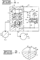
- Fig. 1 is a schematic illustration of one embodiment of the present invention with portions shown in cross-section for illustrative convenience;
- Fig. 2 is a somewhat enlarge sectional view taken along line 2-2 of Fig. 1; and
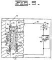
- Figs. 3 through 6 are schematic illustrations of other embodiments of the present invention.
- A pressure compensated flow amplifying poppet valve is generally indicated by the
reference numeral 10 and includes acomposite valve body 11 and avalve element 12. The body includes a pair of concentriccylindrical bores annuluses 16,17, aninlet port 19 in communication with the annulus 17, anoutlet port 21 in communication with thecylindrical bore 14, and avalve seat 22 between thecylindrical bore 14 and theoutlet port 21. Thecylindrical bore 14 is formed in anannular sleeve 24 suitably seated in abore 26. A plurality offlow modulating ports 27 extend through thesleeve 24 to communicate the annulus 17 with thecylindrical bore 14. - The
valve element 12 has a pair ofconcentric spool portions cylindrical bores annular reaction surface 31 therebetween. Acontrol chamber 32 is defined by theannulus 16 and the end of thespool portion 28. The area of the end of thespool portion 28 is substantially larger than area of thesurface 31. Thespool portion 29 terminates at aconical end portion 34 and cooperates with theports 27 to provide a mainflow regulating orifice 35. A pair of variable areaflow control orifices 36 are provided in thespool portion 28 to communicate theinlet port 19 with thecontrol chamber 32. Theorifices 36 are in the form of a pair of axially extendingrectangular slots 37 connected to theinlet port 19 through a pair of diagonally extendingpassages 38. As more clearly shown in Fig. 2, a minimum flow area "a" of theslots 37 is always open to continuously communicate theinlet port 19 with thecontrol chamber 32. A light-weight spring 39 disposed between thevalve element 12 and thebody 11 resiliently urges theconical end portion 34 into sealing engagement with thevalve seat 22. - A pressure compensated
variable displacement pump 41 is connected to theinlet port 19 and amotor 42 is connected to theoutlet port 21. - The
poppet valve 10 also includes a flow regulating passage means 43 communicating thecontrol chamber 32 with theoutlet port 21, a valve means 44 for controllably regulating the fluid flow through the passage means 43, and means 45 for establishing a restricted compensatingflow path 46 from thecontrol chamber 32 to theoutlet port 21 parallel to the passage means 43. The passage means 43 includes aregulating passage 47 connected to and extending between thecontrol chamber 32 and theoutlet port 21. The valve means 44 includes apressure reducing valve 48 and aflow regulating valve 49 serially disposed in the regulatingpassage 47. Theflow regulating valve 49 is movable between a closed position blocking communication through the regulatingpassage 47 and an infinitely variable open position establishing a variable regulatingorifice 50 for regulating fluid flow through the regulatingpassage 47. Thepressure reducing valve 48 maintains a substantially constant pressure drop across the regulatingvalve 49 at its open position. - The
flow path 46 includes acompensating passage 51 connected to thepassage 47 on opposite sides of thevalves means 45 includes ameans 52 for controlling fluid flow through thepassage 51 of theflow path 46. The regulatingmeans 52 includes a compensatingorifice 53 and a compensatingvalve 54 serially disposed in thepassage 51. The compensatingvalve 54 is movable between a closed position and an open position to modulatably control fluid flow through thepassage 51. The compensatingorifice 53 establishes a maximum flow area through thepassage 51 at the fully open position of the compensatingvalve 54. - In this embodiment the
pressure regulating valve 48 and the compensatingvalve 54 are shown combined into a single valve movable between positions A, B, and C. Such movement can be by any convenient means such as pilot operation, electrical solenoid operation or mechanical operation. Alternatively, the flow regulating valve and compensatingvalve 54 may be separate valves which can be sequentially operated. Also, theorifice 53 may be incorporated within the compensatingvalve 54 and be established by the maximum opening area of the compensating valve. - Other embodiments of a pressure compensating flow amplifying
poppet valve 10 of the present invention are disclosed in Figs. 3-6. It is noted that the same reference numerals of the first embodiment are used to designate similarly constructed counterpart elements of these embodiments. - In the embodiment of Fig. 3, the compensating
passage 51 connects the cylindrical bore 13 with theoutlet port 21 and the compensatingvalve 54 is formed by aslot 57 provided in thespool portion 28 of thevalve element 12. Theslot 57 is in continuous communication with thecontrol chamber 32. Communication through the compensatingpassage 51 is blocked by thespool portion 28 when theend portion 34 is seated against thevalve seat 22. - The embodiment of Fig. 4 is similar to the embodiment of Fig. 3 with the exception that the establishing means 45 includes having the
end portion 34 of thevalve element 12 axially separated from thespool portion 29 by a reduceddiameter portion 58, thevalve seat 22 axially spaced from theports 27 by anannular chamber 59 formed in thesleeve 24, and the compensatingpassage 51 connecting thebore 13 with theannulus 59. - In the embodiment of Fig. 5, the compensating
passage 51, theorifice 53, and a compensatingvalve 62 are disposed within thevalve element 12. More specifically, the compensatingvalve 62 includes apoppet valve 63 having apiston 64 slidably disposed in anaxial bore 66 and defines anactuating chamber 67 in communication with theinlet port 19 through anopening 68. Aconical valve portion 69 of thepoppet valve 63 is biased against a valve seat 71 by aspring 72 disposed in achamber 73 open to thecontrol chamber 32. The compensatingpassage 51 connects thebore 66 adjacent the valve seat 71 with theoutlet port 21. - In the embodiment of Fig. 6, the valve means 44 includes a fixed
orifice 74 disposed in the regulatingpassage 47 and apressure regulating valve 76 also disposed in the regulatingpassage 47 upstream of theorifice 74 to controllably vary the pressure drop across the fixedorifice 74. The compensatingvalve 54 is built into the regulatingvalve 76 and is disposed in thepassage 51 of the compensatingflow path 46 similar to the embodiment of Fig. 1. - With respect to the embodiment of Fig. 1, when both the regulating
valve 49 and compensatingvalve 54 are in the closed position represented by the letter "A" as shown in the Fig. 1, fluid from theinlet port 19 passes through thepassages 38 and theslots 37 into thecontrol chamber 32. Since there is no fluid flow through thepassages control chamber 32 is substantially equal to the fluid pressure in theinlet port 19. With the area of thevalve element 12 subjected to the fluid pressure in thecontrol chamber 32 being greater than the area of thereaction surface 31, thevalve element 12 is urged downwardly so that theend portion 34 remains sealingly engaged with thevalve seat 22. If the fluid pressures in theinlet port 19 and theoutlet port 21 are equal, thespring 39 holds the valve element in the sealing position. - In the use of the embodiment of Fig. 1 of the present invention, actuation of the
poppet valve 10 is initiated by initially controllably moving the compensatingvalve 54 from the "A" position to the "B" position. This controllably establishes fluid flow from theinlet port 19 through thepassages 38, the aggregate open area "a" of theslots 37, thecontrol chamber 32, thepassage 51, theorifice 53, and the compensatingvalve 54 to theoutlet port 21. Movement of the compensatingvalve 54 between the "A" and "B" positions modulatably controls the fluid passing through thepassage 51 while theorifice 53 generally limits the amount of fluid that can pass through thepassage 51 of theflow path 46. In this embodiment, flow through the regulatingvalve 49 at the "B" position is still blocked. The fluid flow through thepassage 51 is fairly low and generally does not generate a pressure drop sufficient to cause thevalve element 12 to move upwardly to unseat theend portion 34 from thevalve seat 22. Such low flow is referred to as impending flow. - Upon further movement of the compensating
valve 54 and the regulatingvalve 49 from the "B" position to the "C" position, fluid flow through theflow path 46 does not increase due to the size of theorifice 53. However, movement of the regulatingvalve 49 between the "B" and "C" positions opens the regulatingorifice 50 and establishes fluid flow through thepassage 47 between thecontrol chamber 32 and theoutlet port 21 sufficient to create a pressure drop between theinlet port 19 and thecontrol chamber 32. At some small regulating flow through the regulatingorifice 50 of the regulatingvalve 47, thevalve element 12 moves upwardly and lifts theend portion 34 from thevalve seat 22 but does not uncover any of the modulatingports 27 in thesleeve 24. With increasing regulating flow through the regulatingorifice 50 and increasing movement of thevalve element 12, thespool portion 29 begins uncovering theports 27 establishing fluid flow through the mainflow regulating orifice 35 from theinlet port 19 to theoutlet port 21. The upward movement of thevalve element 12 and thus the degree of opening of theports 27 is determined by the flow between theinlet port 19 and thecontrol chamber 32 which in turn is modulatably controlled by the degree of opening of theflow regulating valve 49. At a steady state position of the regulatingvalve 49, the flow through theslots 37 equals the aggregate flow through thepassages main orifice 35 is a proportional amount greater than the flow through the regulatingorifice 50. - The
pressure reducing valve 48 functions in its usual manner to maintain a constant pressure drop across the regulatingvalve 49. The combination of the compensatingorifice 53 and the compensatingvalve 54 in theflow path 46 disposed in parallel with thepressure reducing valve 48 and the regulatingvalve 54 makes the poppet valve substantially fully compensated. Thus, the fluid flow through the inlet and outlet ports remains substantially constant at a given setting of the regulatingvalve 49 regardless of pressure differentials between the inlet andoutlet ports - In general, to make the poppet valve fully compensated, the size of the compensating
orifice 53 will be slightly less than the aggregate area "a" of theslots 37 that is always open. However, the size relationship between theorifice 53 and the aggregate area "a" can be varied to compensate for closing flow forces acting on thevalve element 12 and the amount of fluid leaking between the valve element and thebore 13. Depending on the magnitude of the flow forces and the bore leakage, the size of the compensating orifice may be slightly less than, equal to, or slightly greater than the open area "a" of the slots. In actuality the size of the compensating orifice is preferably selected so that theend portion 34 remains seated when the compensating valve is at the "B" or "C" position and the fluid flow through thepassage 51 is limited by the compensating orifice. - Alternatively, the outlet flow from the
outlet port 21 can be purposely made to increase or decrease with increasing pressure drop between the inlet and outlet ports by changing the size of the compensatingorifice 53 relative to the area "a" of thecontrol slots 37 which is always open. - In the use of the embodiment of Fig. 3, actuation of the
poppet valve 10 to the open position is initiated by opening theflow regulating orifice 50 of the regulatingvalve 49. At some small regulated flow through the regulatingorifice 50, thevalve element 12 moves upwardly to unseat theend portion 34 from theseat 22 and theslot 57 communicated with the compensatingpassage 51. A portion of the impending flow passes through the compensatingpassage 51 and the rest passes through the regulatingpassage 47. Increasing the regulating flow through the regulating orifice causes thevalve element 12 to continue moving upwardly. At a predetermined position of thevalve element 12, the fixedorifice 53 limits the fluid flow through thepassage 51. Shortly thereafter, thespool portion 29 begins uncovering the modulatingports 27 thereby allowing fluid flow from theinlet port 19 to pass through theports 27 to theoutlet port 21. - Operation of the embodiment of Fig. 4 is essentially the same as the Fig. 3 embodiment. However, with this embodiment, the compensating
passage 51 is positively blocked from theoutlet port 21 when theend portion 34 is seated against thevalve seat 22. Thus, any leakage flow past thespool portion 28 is positively blocked from theoutlet port 21. The initial upward movement of thevalve element 12 unseats theend portion 34 thereby immediately establishing communication between the compensatingpassage 51 and theoutlet port 21. - Referring to the embodiment of Fig. 5 with the regulating
valve 49 in the blocked position and theend portion 34 seated against thevalve seat 22, the pressure in thecontrol chamber 32 equals the pressure in theinlet port 19. Thepoppet valve 63 is thus urged to the closed position shown by thespring 72. When the regulatingorifice 50 of the regulatingvalve 49 is initially opened to initiate regulating fluid flow through the regulatingpassage 47, the pressure in thecontrol chamber 32 decreases due to the pressure drop across theslots 37. At some small pressure drop, thepoppet valve 63 opens allowing fluid flow from thecontrol chamber 32 through the compensatingpassage 51 and theorifice 53 to theoutlet port 21. At some predetermined pressure drop, thepoppet valve 63 will become fully open. The compensatingorifice 53 limits the amount of fluid that can pass through thepassage 51 at the open position of the compensatingvalve 53. After the maximum flow rate through thepassage 51 has been reached and with some additional regulating flow, thevalve element 12 moves upwardly unseating theend portion 34 from thevalve seat 22 and eventually thespool portion 29 will uncover theports 27 to initiate the main flow between theinlet port 19 through theports 27 to theoutlet port 21. - Operation of the embodiment of Fig. 6 is initiated by moving the combined
pressure regulating valve 76 and the compensatingvalve 54 simultaneously. The initial movement of the compensatingvalve 54 permits fluid to flow through the compensatingpassage 51 from thecontrol chamber 32 to theoutlet port 21. At some predetermined point, the fluid flow rate through thepassage 51 matches the size of the fixedorifice 53 so that further opening of the compensatingvalve 54 has no effect on fluid flow through thepassage 51. Shortly after that occurs, thepressure regulating valve 76 opens to allow fluid flow through the regulatingpassage 47 to create a pressure drop between theinlet port 19 and thecontrol chamber 32. As previously described, with increasing flow through the regulatingpassage 47, thevalve element 12 initially moves upwardly sufficient to unseat theend portion 34 from thevalve seat 22 with thespool portion 29 subsequently uncovering theports 27 to initiate fluid flow from theinlet port 19 to theoutlet port 21. Thepressure regulating valve 76 is operative to controllably vary the pressure drop across the fixedorifice 74 in proportion to the input force applied to the regulating valve for moving it to the open position. - In view of the foregoing, it is readily apparent that the structure of the present invention provides an improved pressure compensating flow amplifying poppet valve which makes the poppet valve substantially fully pressure compensated. This is accomplished by providing a compensating valve and compensating orifice in a compensating passage disposed in parallel with the valve means in the regulating flow passage such that the small flow through the compensating passage essentially equals the amount of flow that can pass through the slots in the main valve element before the main flow is established between the inlet and outlet ports.
- Other aspects, objects, and advantages of this invention can be obtained from a study of the drawings, the disclosure, and the appended claims.
Claims (21)
- A pressure compensated flow amplifying poppet valve (10) comprising;an inlet port (19);an outlet port (21);a cylindrical bore (13);an elongate valve element (12) having a first spool portion (28) slidably disposed in the bore (13) defining a control chamber (32), the valve element (12) being movable between a closed position at which the inlet port (19) is blocked from the outlet port (21) and an open position at which a main flow regulating orifice (35) is established between the inlet and outlet ports (19,21), the first spool portion (28) including a variable orifice (36) between the inlet port (19) and the control chamber (32);flow regulating passage means (43) communicating the control chamber (32) with the outlet port (21); andvalve means (44) for controllably regulating the fluid flow through the flow regulating passage means (43); characterized bymeans (45) for establishing a restricted compensating flow path (46) from the control chamber (32) to the outlet port (21) parallel to the flow regulating passage means (43), the establishing means (45) including a compensating orifice (53) disposed in the compensating flow path (46) and a compensating valve (54,62) movable between a variable open position for controlling fluid flow through the compensating flow path (46) and a closed position blocking fluid flow through the compensating flow path.
- The flow amplifying poppet valve (10) of claim 1 wherein the compensating orifice (53) establishes a maximum flow area to limit fluid flow through the compensating flow path (46) at the open position of the pressure compensating valve (54).
- The flow amplifying poppet valve (10) of claim 2 including an annular valve seat (22) disposed between the inlet and outlet ports (19,21), the valve element (12) having an end portion (34) sealingly engaging the valve seat (22) at the closed position of the valve element (12).
- The flow amplifying poppet valve (10) of claim 3 wherein one of the valve seats (22) and the end portion (34) has a conical shape.
- The flow amplifying poppet valve (10) of claim 3 including a second cylindrical bore (14) coaxial with the first bore (13) and a plurality of ports (27) communicating the inlet port (21) with the second bore (14), and the valve element (22) includes a second spool portion (29) slidably disposed in the second bore (14) with the second spool portion (29) and the ports (27) cooperating to define the main flow regulating orifice (35) when the valve element (12) is at the open position.
- The flow amplifying poppet valve (10) of claim 5 wherein the variable orifice (36) includes an axially extending slot (37) disposed in the first spool portion (28) and being in continuous communication with the inlet port (19).
- The flow amplifying poppet valve (10) of claim 6 wherein the ports (27) are axially spaced from the valve seat (22) and movement of the valve element (12) to the open position establishes communication therethrough.
- The flow amplifying poppet valve (10) of claim 7 wherein the axially extending slot (37) has a minimum flow area which is always open to the control chamber (32) and the compensating orifice (53) has an area substantially equal to the minimum flow area.
- The flow amplifying poppet valve (10) of claim 7 wherein the valve means (44) includes a flow regulating valve (49) disposed in the flow regulating passage means (43) and movable between a closed position blocking communication through the flow regulating passage means (43) and an infinitely variable open position establishing variable communication through the flow regulating passage means (43), and a pressure reducing valve (48) disposed in the flow regulating passage means (43) in series flow relationship with the flow regulating valve (49) for maintaining a substantial constant pressure drop across the flow regulating valve at its open position.
- The flow amplifying poppet valve (10) of claim 9 wherein the compensating flow path (46) includes a compensating passage (51) communicating the control chamber (32) with the outlet port (21), the compensating orifice (53) and the compensating valve (54) being disposed in the compensating passage.
- The flow amplifying poppet valve (10) of claim 10 wherein movement of the flow regulating valve (49) and the pressure compensating valve (54) is sequential wherein the compensating valve (54) opens first and reaches a position to establish maximum fluid flow through the compensating passage (51) before the flow regulating valve (49) opens.
- The flow amplifying poppet valve (10) of claim 7 wherein the compensating flow path (46) includes a compensating passage (51) communicating the first bore (13) with the outlet port (21) and the compensating valve (54) includes the first spool portion (28) and a fluid flow regulating passage (57) in the first spool portion (28) in continuous communication with the control chamber (32).
- The flow amplifying poppet valve (10) of claim 12 wherein the regulating passage (57) is blocked from the compensating passage (51) when the valve element (12) is in the closed position, and in communication with the compensating passage (51) prior to the valve element (12) reaching its open position.
- The flow amplifying poppet valve (10) of claim 13 wherein the valve means (44) includes a flow regulating valve (49) disposed in the flow regulating passage means (43) and movable between a closed position blocking communication through the flow regulating passage means (43) and an infinitely variable open position establishing variable communication through the flow regulating passage means (43), and a pressure reducing valve disposed in the flow regulating passage means (43) in series flow relationship with the flow regulating valve (49) for maintaining a substantial constant pressure drop across the flow regulating valve at its open position.
- The flow amplifying poppet valve (10) of claim 7 wherein the compensating flow path (46) includes means defining an annular chamber (59) blocked from the outlet port (21) at the closed position of the valve element (12) and in communication with the outlet port at the open position of the valve element (12), and a compensating passage (51) communicating the first bore (13) with the annular chamber (59), and the compensating valve (54) includes the first spool portion (28) and a fluid flow regulating passage (57) in the first spool portion in continuous communication with the control chamber (32).
- The flow amplifying poppet valve (10) of claim 15 wherein the regulating passage (57) is blocked from the compensating passage (51) when the valve element (12) is in the closed position, and in communication with the compensating passage (51) prior to the valve element (12) reaching its open position.
- The flow amplifying poppet valve (10) of claim 16 wherein the valve means (44) includes a flow regulating valve (49) disposed in the flow regulating passage means (43) and movable between a closed position blocking communication through the flow regulating passage means (43) and an infinitely variable open position establishing variable communication through the flow regulating passage means (43), and a pressure reducing valve disposed in the flow regulating passage means (43) in series flow relationship with the flow regulating valve (49) for maintaining a substantial constant pressure drop across the flow regulating valve at its open position.
- The flow amplifying poppet valve (10) of claim 7 wherein the compensating flow path (46) includes a compensating passage (51) in the valve element (12) and being in continuous communication with the outlet port (21), and the compensating valve (62) includes a bore (66) in the valve element (12) and a poppet valve (63) disposed in the bore (66) of the valve element (12), the poppet valve (63) blocking communication between the control chamber (32) and the compensating passage (51) at its closed position and establishing communication between the control chamber (32) and the compensating passage (51) at its open position.
- The flow amplifying poppet valve (10) of claim 18 including a valve seat (71) adjacent the bore (66) in the valve element (12) and a conical portion (69) in sealing engagement with the valve seat (71) at the closed position of the compensating valve (62) and a spring (72) resiliently urging the compensating valve (62) to the closed position.
- The flow amplifying poppet valve (10) of claim 19 wherein the poppet valve (63) includes a piston (64) slidably disposed in the bore (66) of the valve element (12) defining an actuating chamber (67), and an opening (68) communicating the inlet port (21) with the actuating chamber (67).
- The flow amplifying poppet valve (10) of claim 7 wherein the valve means (44) includes a fixed orifice (74) disposed in the flow regulating passage means (43) and a pressure regulating valve (76) disposed in series with the fixed orifice (74) and operative to maintain a variable pressure drop across the fixed orifice (74) proportional to an input force applied to the pressure regulating valve.
Applications Claiming Priority (3)
| Application Number | Priority Date | Filing Date | Title |
|---|---|---|---|
| US754092 | 1985-07-15 | ||
| US07/754,092 US5137254A (en) | 1991-09-03 | 1991-09-03 | Pressure compensated flow amplifying poppet valve |
| PCT/US1991/008282 WO1993005303A1 (en) | 1991-09-03 | 1991-11-12 | Pressure compensated flow amplifying poppet valve |
Publications (2)
| Publication Number | Publication Date |
|---|---|
| EP0602036A1 EP0602036A1 (en) | 1994-06-22 |
| EP0602036B1 true EP0602036B1 (en) | 1996-05-29 |
Family
ID=25033457
Family Applications (1)
| Application Number | Title | Priority Date | Filing Date |
|---|---|---|---|
| EP92904925A Expired - Lifetime EP0602036B1 (en) | 1991-09-03 | 1991-11-12 | Pressure compensated flow amplifying poppet valve |
Country Status (6)
| Country | Link |
|---|---|
| US (1) | US5137254A (en) |
| EP (1) | EP0602036B1 (en) |
| JP (1) | JP3090275B2 (en) |
| AU (1) | AU1250892A (en) |
| DE (1) | DE69119914T2 (en) |
| WO (1) | WO1993005303A1 (en) |
Cited By (1)
| Publication number | Priority date | Publication date | Assignee | Title |
|---|---|---|---|---|
| WO2017202485A1 (en) * | 2016-05-25 | 2017-11-30 | Hydac System Gmbh | Valve device |
Families Citing this family (38)
| Publication number | Priority date | Publication date | Assignee | Title |
|---|---|---|---|---|
| US5207059A (en) * | 1992-01-15 | 1993-05-04 | Caterpillar Inc. | Hydraulic control system having poppet and spool type valves |
| US5421545A (en) * | 1993-09-03 | 1995-06-06 | Caterpillar Inc. | Poppet valve with force feedback control |
| US5645263A (en) * | 1993-10-04 | 1997-07-08 | Caterpillar Inc. | Pilot valve for a flow amplyifying poppet valve |
| JP3685923B2 (en) * | 1998-04-21 | 2005-08-24 | 日立建機株式会社 | Pipe break control valve device |
| US6089528A (en) * | 1998-12-18 | 2000-07-18 | Caterpillar Inc. | Poppet valve control with sealing element providing improved load drift control |
| US6047944A (en) * | 1999-02-25 | 2000-04-11 | Caterpillar Inc. | Poppet with a flow increasing element for limiting movement thereof in a poppet valve |
| KR100395893B1 (en) * | 1999-10-20 | 2003-08-27 | 히다치 겡키 가부시키 가이샤 | Pipe breakage control valve device |
| US6557822B1 (en) * | 2000-11-21 | 2003-05-06 | Caterpillar Inc. | Dynamically stable flow amplifying poppet valve |
| US6769252B2 (en) | 2001-12-10 | 2004-08-03 | Caterpillar Inc | Fluid system having variable pressure relief |
| US6694859B2 (en) | 2002-03-28 | 2004-02-24 | Caterpillar Inc | Variable pressure relief valve |
| JP4160530B2 (en) * | 2004-04-28 | 2008-10-01 | 日立建機株式会社 | Control valve device and pressure circuit |
| US7293579B2 (en) * | 2004-07-08 | 2007-11-13 | Caterpillar Inc. | Poppet valve arrangements |
| US7204084B2 (en) * | 2004-10-29 | 2007-04-17 | Caterpillar Inc | Hydraulic system having a pressure compensator |
| US7243493B2 (en) * | 2005-04-29 | 2007-07-17 | Caterpillar Inc | Valve gradually communicating a pressure signal |
| US7204185B2 (en) * | 2005-04-29 | 2007-04-17 | Caterpillar Inc | Hydraulic system having a pressure compensator |
| US7194856B2 (en) * | 2005-05-31 | 2007-03-27 | Caterpillar Inc | Hydraulic system having IMV ride control configuration |
| US7302797B2 (en) * | 2005-05-31 | 2007-12-04 | Caterpillar Inc. | Hydraulic system having a post-pressure compensator |
| US7258058B2 (en) * | 2005-08-31 | 2007-08-21 | Caterpillar Inc | Metering valve with integral relief and makeup function |
| US7210396B2 (en) * | 2005-08-31 | 2007-05-01 | Caterpillar Inc | Valve having a hysteretic filtered actuation command |
| US20070045584A1 (en) * | 2005-08-31 | 2007-03-01 | Diamond Power International, Inc. | Low loss poppet valve for a cleaning device and a method of delivering a cleaning fluid therewith |
| US7331175B2 (en) * | 2005-08-31 | 2008-02-19 | Caterpillar Inc. | Hydraulic system having area controlled bypass |
| US20100043418A1 (en) * | 2005-09-30 | 2010-02-25 | Caterpillar Inc. | Hydraulic system and method for control |
| US7614336B2 (en) * | 2005-09-30 | 2009-11-10 | Caterpillar Inc. | Hydraulic system having augmented pressure compensation |
| US7320216B2 (en) * | 2005-10-31 | 2008-01-22 | Caterpillar Inc. | Hydraulic system having pressure compensated bypass |
| KR100800081B1 (en) * | 2006-08-29 | 2008-02-01 | 볼보 컨스트럭션 이키프먼트 홀딩 스웨덴 에이비 | Hydraulic Circuit of Excavator Option |
| DE602006006676D1 (en) * | 2006-09-01 | 2009-06-18 | Parker Hannifin Ab | valve assembly |
| DE502006008678D1 (en) * | 2006-12-05 | 2011-02-17 | Festo Ag & Co Kg | Soft start valve device |
| US20080295681A1 (en) * | 2007-05-31 | 2008-12-04 | Caterpillar Inc. | Hydraulic system having an external pressure compensator |
| US8479504B2 (en) * | 2007-05-31 | 2013-07-09 | Caterpillar Inc. | Hydraulic system having an external pressure compensator |
| US7621211B2 (en) * | 2007-05-31 | 2009-11-24 | Caterpillar Inc. | Force feedback poppet valve having an integrated pressure compensator |
| US20110017310A1 (en) * | 2007-07-02 | 2011-01-27 | Parker Hannifin Ab | Fluid valve arrangement |
| EP2241764B1 (en) * | 2009-04-17 | 2011-08-31 | HAWE Hydraulik SE | Seat valve with circulating valve and pressure scale function |
| US8684037B2 (en) | 2009-08-05 | 2014-04-01 | Eaton Corportion | Proportional poppet valve with integral check valve |
| US8631650B2 (en) | 2009-09-25 | 2014-01-21 | Caterpillar Inc. | Hydraulic system and method for control |
| US8291934B2 (en) * | 2010-01-20 | 2012-10-23 | Eaton Corporation | Proportional valve assembly |
| US8770543B2 (en) | 2011-07-14 | 2014-07-08 | Eaton Corporation | Proportional poppet valve with integral check valves |
| CN112443527B (en) * | 2020-12-10 | 2023-11-07 | 徐州阿马凯液压技术有限公司 | High-flow-precision flow amplifying valve |
| CN114396497B (en) * | 2021-12-31 | 2024-05-24 | 浙江大学温州研究院 | Passive micro valve with constant flow output and method thereof |
Family Cites Families (9)
| Publication number | Priority date | Publication date | Assignee | Title |
|---|---|---|---|---|
| US3175800A (en) * | 1961-06-20 | 1965-03-30 | Int Harvester Co | Hydraulic control system and unloading valve therefor |
| US3561488A (en) * | 1969-07-01 | 1971-02-09 | Sanders Associates Inc | Fluid flow control valve |
| DE3132909A1 (en) * | 1981-08-20 | 1983-03-03 | Hans-Gebhard Krines | "VALVE DEVICE, IN PARTICULAR FOR DIE CASTING MACHINES |
| SE439342C (en) * | 1981-09-28 | 1996-11-18 | Bo Reiner Andersson | Valve device for controlling a linear or rotary hydraulic motor |
| DE3246738C2 (en) * | 1982-09-28 | 1987-02-05 | Dr. H. Tiefenbach Gmbh & Co, 4300 Essen | Self-medium controlled hydraulic valve with adjustable flow cross-section |
| DE3343620C2 (en) * | 1983-12-02 | 1986-09-04 | Glyco-Antriebstechnik Gmbh, 6200 Wiesbaden | Controllable 2-way valve for pressure and flow control of a liquid flow |
| AU603907B2 (en) * | 1987-06-30 | 1990-11-29 | Hitachi Construction Machinery Co. Ltd. | Hydraulic drive system |
| DE68910721T2 (en) * | 1988-05-12 | 1994-03-10 | Hitachi Construction Machinery | Hydraulic drive device for crawler construction vehicles. |
| US4846216A (en) * | 1988-07-05 | 1989-07-11 | Robert E. Raymond | Fluid power valve device |
-
1991
- 1991-09-03 US US07/754,092 patent/US5137254A/en not_active Expired - Lifetime
- 1991-11-12 AU AU12508/92A patent/AU1250892A/en not_active Abandoned
- 1991-11-12 EP EP92904925A patent/EP0602036B1/en not_active Expired - Lifetime
- 1991-11-12 JP JP50517792A patent/JP3090275B2/en not_active Expired - Fee Related
- 1991-11-12 DE DE69119914T patent/DE69119914T2/en not_active Expired - Fee Related
- 1991-11-12 WO PCT/US1991/008282 patent/WO1993005303A1/en not_active Ceased
Cited By (3)
| Publication number | Priority date | Publication date | Assignee | Title |
|---|---|---|---|---|
| WO2017202485A1 (en) * | 2016-05-25 | 2017-11-30 | Hydac System Gmbh | Valve device |
| CN109477499A (en) * | 2016-05-25 | 2019-03-15 | Hydac系统和服务有限公司 | Valve gear |
| CN109477499B (en) * | 2016-05-25 | 2020-10-30 | Hydac系统和服务有限公司 | Valve device |
Also Published As
| Publication number | Publication date |
|---|---|
| US5137254A (en) | 1992-08-11 |
| JP3090275B2 (en) | 2000-09-18 |
| WO1993005303A1 (en) | 1993-03-18 |
| DE69119914D1 (en) | 1996-07-04 |
| EP0602036A1 (en) | 1994-06-22 |
| JPH07503083A (en) | 1995-03-30 |
| DE69119914T2 (en) | 1996-10-02 |
| AU1250892A (en) | 1993-04-05 |
Similar Documents
| Publication | Publication Date | Title |
|---|---|---|
| EP0602036B1 (en) | Pressure compensated flow amplifying poppet valve | |
| US5421545A (en) | Poppet valve with force feedback control | |
| US5878647A (en) | Pilot solenoid control valve and hydraulic control system using same | |
| US5868059A (en) | Electrohydraulic valve arrangement | |
| US3722543A (en) | Pressure compensated control valve | |
| US8424836B2 (en) | Bidirectional force feedback poppet valve | |
| US4462566A (en) | Pressure compensated flow control system | |
| US4461314A (en) | Electrohydraulic valve | |
| JP3703265B2 (en) | Hydraulic control device | |
| US4327763A (en) | Dual control input flow control valve | |
| EP0231876B1 (en) | Hydraulic pressure control system | |
| WO1993009350A1 (en) | Pressure compensated flow amplifying poppet valve | |
| JPS6033446Y2 (en) | Pilot pressure regulating valve for pressure control valve equipment | |
| US5876184A (en) | Electrohydraulic pressure regulating valve | |
| US4246934A (en) | Remotely controlled load responsive valves | |
| JP2577225B2 (en) | Flow control valve | |
| JPS6347583A (en) | Holding valve | |
| EP0102960A4 (en) | Pressure compensated fluid control valve with maximum flow adjustment. | |
| CA1181658A (en) | Dual control input flow control valve | |
| JPH087458Y2 (en) | Stacked pressure reducing valve | |
| JP3298899B2 (en) | Load-sensitive control device | |
| JPS5855448Y2 (en) | Seat type flow regulating valve device | |
| EP0113708B1 (en) | Dual control input flow control valve | |
| JP3727750B2 (en) | Hydraulic control device | |
| US4436019A (en) | Pressure compensated fluid control valve |
Legal Events
| Date | Code | Title | Description |
|---|---|---|---|
| PUAI | Public reference made under article 153(3) epc to a published international application that has entered the european phase |
Free format text: ORIGINAL CODE: 0009012 |
|
| 17P | Request for examination filed |
Effective date: 19940204 |
|
| AK | Designated contracting states |
Kind code of ref document: A1 Designated state(s): BE DE FR GB IT SE |
|
| 17Q | First examination report despatched |
Effective date: 19950412 |
|
| GRAH | Despatch of communication of intention to grant a patent |
Free format text: ORIGINAL CODE: EPIDOS IGRA |
|
| GRAA | (expected) grant |
Free format text: ORIGINAL CODE: 0009210 |
|
| AK | Designated contracting states |
Kind code of ref document: B1 Designated state(s): BE DE FR GB IT SE |
|
| PG25 | Lapsed in a contracting state [announced via postgrant information from national office to epo] |
Ref country code: IT Free format text: LAPSE BECAUSE OF FAILURE TO SUBMIT A TRANSLATION OF THE DESCRIPTION OR TO PAY THE FEE WITHIN THE PRE;WARNING: LAPSES OF ITALIAN PATENTS WITH EFFECTIVE DATE BEFORE 2007 MAY HAVE OCCURRED AT ANY TIME BEFORE 2007. THE CORRECT EFFECTIVE DATE MAY BE DIFFERENT FROM THE ONE RECORDED.SCRIBED TIME-LIMIT Effective date: 19960529 Ref country code: FR Effective date: 19960529 Ref country code: BE Effective date: 19960529 |
|
| REF | Corresponds to: |
Ref document number: 69119914 Country of ref document: DE Date of ref document: 19960704 |
|
| PG25 | Lapsed in a contracting state [announced via postgrant information from national office to epo] |
Ref country code: SE Effective date: 19960829 |
|
| EN | Fr: translation not filed | ||
| PLBE | No opposition filed within time limit |
Free format text: ORIGINAL CODE: 0009261 |
|
| STAA | Information on the status of an ep patent application or granted ep patent |
Free format text: STATUS: NO OPPOSITION FILED WITHIN TIME LIMIT |
|
| 26N | No opposition filed | ||
| PGFP | Annual fee paid to national office [announced via postgrant information from national office to epo] |
Ref country code: GB Payment date: 20010926 Year of fee payment: 11 |
|
| REG | Reference to a national code |
Ref country code: GB Ref legal event code: IF02 |
|
| PG25 | Lapsed in a contracting state [announced via postgrant information from national office to epo] |
Ref country code: GB Free format text: LAPSE BECAUSE OF NON-PAYMENT OF DUE FEES Effective date: 20021112 |
|
| GBPC | Gb: european patent ceased through non-payment of renewal fee | ||
| PGFP | Annual fee paid to national office [announced via postgrant information from national office to epo] |
Ref country code: DE Payment date: 20081128 Year of fee payment: 18 |
|
| PG25 | Lapsed in a contracting state [announced via postgrant information from national office to epo] |
Ref country code: DE Free format text: LAPSE BECAUSE OF NON-PAYMENT OF DUE FEES Effective date: 20100601 |