EP0601516B1 - Cooling device - Google Patents
Cooling device Download PDFInfo
- Publication number
- EP0601516B1 EP0601516B1 EP93119629A EP93119629A EP0601516B1 EP 0601516 B1 EP0601516 B1 EP 0601516B1 EP 93119629 A EP93119629 A EP 93119629A EP 93119629 A EP93119629 A EP 93119629A EP 0601516 B1 EP0601516 B1 EP 0601516B1
- Authority
- EP
- European Patent Office
- Prior art keywords
- magnetic
- cooling device
- flat plates
- flat
- magnetic field
- Prior art date
- Legal status (The legal status is an assumption and is not a legal conclusion. Google has not performed a legal analysis and makes no representation as to the accuracy of the status listed.)
- Expired - Lifetime
Links
Images





Classifications
-
- H—ELECTRICITY
- H10—SEMICONDUCTOR DEVICES; ELECTRIC SOLID-STATE DEVICES NOT OTHERWISE PROVIDED FOR
- H10W—GENERIC PACKAGES, INTERCONNECTIONS, CONNECTORS OR OTHER CONSTRUCTIONAL DETAILS OF DEVICES COVERED BY CLASS H10
- H10W40/00—Arrangements for thermal protection or thermal control
- H10W40/40—Arrangements for thermal protection or thermal control involving heat exchange by flowing fluids
- H10W40/43—Arrangements for thermal protection or thermal control involving heat exchange by flowing fluids by flowing gases, e.g. forced air cooling
-
- F—MECHANICAL ENGINEERING; LIGHTING; HEATING; WEAPONS; BLASTING
- F04—POSITIVE - DISPLACEMENT MACHINES FOR LIQUIDS; PUMPS FOR LIQUIDS OR ELASTIC FLUIDS
- F04B—POSITIVE-DISPLACEMENT MACHINES FOR LIQUIDS; PUMPS
- F04B43/00—Machines, pumps, or pumping installations having flexible working members
- F04B43/02—Machines, pumps, or pumping installations having flexible working members having plate-like flexible members, e.g. diaphragms
- F04B43/04—Pumps having electric drive
- F04B43/043—Micropumps
-
- F—MECHANICAL ENGINEERING; LIGHTING; HEATING; WEAPONS; BLASTING
- F04—POSITIVE - DISPLACEMENT MACHINES FOR LIQUIDS; PUMPS FOR LIQUIDS OR ELASTIC FLUIDS
- F04B—POSITIVE-DISPLACEMENT MACHINES FOR LIQUIDS; PUMPS
- F04B45/00—Pumps or pumping installations having flexible working members and specially adapted for elastic fluids
- F04B45/04—Pumps or pumping installations having flexible working members and specially adapted for elastic fluids having plate-like flexible members, e.g. diaphragms
- F04B45/047—Pumps having electric drive
-
- H—ELECTRICITY
- H02—GENERATION; CONVERSION OR DISTRIBUTION OF ELECTRIC POWER
- H02K—DYNAMO-ELECTRIC MACHINES
- H02K99/00—Subject matter not provided for in other groups of this subclass
- H02K99/20—Motors
-
- H—ELECTRICITY
- H02—GENERATION; CONVERSION OR DISTRIBUTION OF ELECTRIC POWER
- H02N—ELECTRIC MACHINES NOT OTHERWISE PROVIDED FOR
- H02N1/00—Electrostatic generators or motors using a solid moving electrostatic charge carrier
- H02N1/002—Electrostatic motors
- H02N1/006—Electrostatic motors of the gap-closing type
-
- H—ELECTRICITY
- H10—SEMICONDUCTOR DEVICES; ELECTRIC SOLID-STATE DEVICES NOT OTHERWISE PROVIDED FOR
- H10W—GENERIC PACKAGES, INTERCONNECTIONS, CONNECTORS OR OTHER CONSTRUCTIONAL DETAILS OF DEVICES COVERED BY CLASS H10
- H10W70/00—Package substrates; Interposers; Redistribution layers [RDL]
- H10W70/60—Insulating or insulated package substrates; Interposers; Redistribution layers
- H10W70/62—Insulating or insulated package substrates; Interposers; Redistribution layers characterised by their interconnections
- H10W70/63—Vias, e.g. via plugs
Definitions
- the present invention relates to a cooling device, a semiconductor package on which the cooling device is mounted and a computer which includes this semiconductor package, and more particularly to a preferred cooling device which dissipates heat from the semiconductor package or a substrate on which the semiconductor package is mounted.
- Japanese Patent Unexamined Publication No. 2-130894 has disclosed a method for blowing air to a plurality of substrates by means of a large size rotation fan which produces air flow in a computer.
- Japanese Patent Unexamined Publication Nos. 2-83958 and 2-196454 have disclosed a cooling method for directly providing a circuit substrate with a miniature size rotation fan.
- Japanese Patent Unexamined Publication No. 62-149158 has disclosed a method for directly providing a circuit substrate with a reciprocating type fan employing a piezo-vibrator instead of the miniature size rotation fan.
- the method in which a miniature size fan or a reciprocating type fan unit employing a piezo-vibrator is directly mounted on a substrate is effective for the substrate on which the semiconductor packages having high heat generation density are mixedly mounted.
- the efficiency of the fan tends to decrease and additionally, since a space for air to be blown to the semiconductor package is needed, a wide space in a direction perpendicular to the substrate is required.
- the reciprocating type fan employing the piezo-vibrator it is necessary to locate the fan away from the surface of the substrate to blow air to the surface of the substrate.
- the height of the fan from the substrate is reduced so that the fan edges operate as if they sweep the surface of the substrate, the fan scans only a part of the substrate surface, thereby the cooling efficiency is not satisfactory.
- a micro-pump for pumping a flow of gas to be used in the epitaxial layer growing process employs a electrically conductive flexible film which is extending across a space defined between two flat plates which are held in a distance from each other by means of spacer plates upon which the ends of the film are clamped by the flat plates.
- the conductive film and electrodes disposed on inner surfaces of the flat plates and coated with isolating linings may get potentials applied thereto to provide an electrostatic field across the space in such a manner that the flexible film performs a reciprocating movement across the space between the flat plates thus moving a gas into and from that space so as to pump that gas to a vacuum chamber for performing the epitaxial layer growing process.
- the micro-pump may serve for the purpose of feeding the vacuum chamber with well-defined doses of gas but since its flexible film is operated through electrostatic fields there is a tendency of generating electric charges which would adversely affect the provide an effective flow of cooling medium through a very limited space as required for cooling semiconductor chips.
- a cooling device mounted on a semiconductor package comprising a flexible film both ends of which are fastened and flexible film driving means for changing shape of the flexible film.
- a cooling device comprising a pair of flat plates which face each other with a space therebetween, a pair of side plates which are disposed on both ends of the plates so as to define that space with the pair of flat plates and a flexible film which is disposed in the space, both ends of the flexible film being fastened near different side plates on different flat plates so that the shape of said flexible film is changeable in said space.
- a cooling device comprising a magnetic flexible film both ends of which are held, two magnetic field generating devices which generate magnetic fields according to electric signals and side plates which are mounted between the two magnetic field generating devices, the shape of the magnetic flexible film being changed by the generated magnetic fields.
- a semiconductor package including a semiconductor chip containing an electronic circuit, a substrate on which the semiconductor chip is mounted and which has an I/O portion for inputting and outputting electric signals to and from the semiconductor chip and a heat dissipation part which expels heat generated from the semiconductor chip, any one of the cooling devices mentioned above being used for the heat dissipation part.
- both ends of the flexible film are fastened near different side plates on different flat plates so that the shape of the flexible film is changeable in the space which is surrounded by the plates. In this manner, the flexible film is fixed so that it is loose, crossing the gap between the flat plates.
- the flexible film comes into contact with one flat plate successively from the portion where the flexible film is fastened to the flat plate.
- the portion which crosses the space between the flat plates of the flexible film is moved along the surface of the flat plate.
- the flexible film in contact with the surface of the one flat plate is separated therefrom and comes into contact with the surface of the other flat plate.
- the portion which crosses the space, of the flexible film is moved reversely.
- the flexible film repeats contact and separation from the flat plates which are heated by the semiconductor package in order to destroy the thermal boundary layer created over the surfaces of the flat plates. This action accelerates heat conduction on the surfaces of the flat plates and expels the heated cooling medium, introducing a new cooling medium from the surrounding area.
- the thermal boundary layer formed over the surface of a heat generating object blocks heat conduction from the surface of the heat generating object.
- Some countermeasures such as increasing the air flow rate or dispersing the air flow have been taken to decrease the effect of the thickness of the boundary layer.
- the present invention allows such heat to be expelled very effectively because the thermal boundary layer formed over the film in contact with the electrode plate is removed together with the film.
- the present invention is considerably different from conventional cooling devices such as a cooling device comprising a reciprocation type fan the end faces of which operate as if they sweep the surface of a substrate by employing a piezo-vibrator.
- the magnetic flexible film which is supported between two magnetic field generating devices is moved up and down by means of magnetic force. It is possible to provide a thin structure cooling device by narrowing the gap between the magnetic field generating plates. Additionally, because, in the present invention, the film is driven by a magnetic force, the cooling device can be driven by low voltages below 5V and easily integrated with a LSI chip.
- a computer comprising a substrate on which a plurality of semiconductor packages are mounted, a case which incorporates the substrate, a keyboard which is disposed on a surface of the case to input information, and a display screen, at least one of the semiconductor packages including a heat dissipation part which expels heat to a surface opposite to a surface fitted to the substrate, any one of the aforementioned cooling devices being used for the heat dissipation part.
- a cooling device of the present invention by disposing a cooling device of the present invention in a semiconductor package, which is contained in a computer including substrates on which semiconductor packages are mounted, and which generates a large amount of heat, it is possible to suppress a rise of the temperature of the semiconductor package and prevent a rise of the temperature of the substrate, both of which allow the electronic circuits to operate properly.
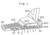
- Fig. 1 is a perspective view with a fragmentary cross section of a computer including cooling devices according to an embodiment of the present invention.
- Fig. 2 is a perspective view of an electromagnetic drive type cooling device according to the basic principle of the present invention.
- Figs. 3a and 3b are a sectional view of the electromagnetic drive type cooling device according to a second detailed embodiment of the present invention and a plan view of a magnetic field generating unit, respectively.
- Fig. 4 is a sectional view of an electromagnetic drive type cooling device according to a third embodiment of the present invention.
- Figs. 5a, 5b and 5c are diagrams showing method for producing a magnetic field generating unit of the electromagnetic drive type cooling device according to a third embodiment of the present invention.
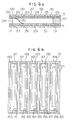
- Figs. 6a and 6b are a sectional view of an electromagnetic drive type cooling device according to a fourth embodiment of the present invention and a plan view of a magnetic field generating unit, respectively.
- Fig. 7 is a plan view of a magnetic field generating unit of an electromagnetic drive type cooling device according to a fifth embodiment of the present invention.
- Figs. 8a and 8b are a sectional view of an electromagnetic drive type cooling device according to a sixth embodiment of the present invention and an explanatory view showing condition of magnetization of a magnetic film used in the cooling device, respectively.
- Fig. 9 is a sectional view of an electromagnetic drive type cooling device according to a seventh embodiment of the present invention.
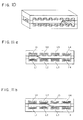
- Fig. 10 is a perspective view of an electromagnetic drive type cooling device according to an eighth embodiment of the present invention.
- Figs. 11a and 11b are diagrams showing operation principle of the electromagnetic drive type cooling device according to a eighth embodiment.
- Fig. 12 is a time-chart showing timing for flowing current to respective coils of the electromagnetic drive type cooling device according to the eighth embodiment.
- Fig. 1 is a fragmentary perspective view including an exterior and a fragmentary cross section showing an interior structure of a computer.
- the computer comprises a case 800 which includes a display screen 803 and a key board 805 mounted on a surface of the case, a substrate 8, on which various semiconductor packages and electronic parts are mounted, disposed inside of the case 800, an external connector 806 and a disk drive 804.
- the case 800 is provided with air ports 801, 802 which are formed on a keyboard side and an external connector side of the case to allow air to circulate in the computer.
- a plurality of semiconductor packages 2 with high heat generation density and semiconductor packages 20 with low heat generation density are mixedly mounted on the substrate 8 disposed in a flat space inside of the case 800.
- the substrate 8 is a multi-layer wiring board on which signal lines and power lines are disposed in multi-layers with insulating layers interposed.
- the semiconductor packages 2, 20 and other electronic parts are electrically connected to each other by means of through holes provided in the substrate and wirings placed on the surface layer.
- a cooling device 1 is bonded to the semi-conductor package 2 which has high heat generation density by high heat conductive adhesive on a side, opposite the substrate 8, of the semiconductor package.
- Fig. 2 shows an expanded view of the semiconductor package 2 on which the cooling device 1 is mounted.
- Fig. 2 is a perspective view showing the construction of the cooling device.
- the cooling device comprises a flexible magnetic film 70, side plates 103, 104, 102 which hold both ends of the film, upper and lower magnetic field generating units 73, 74 which drive the film held by the side plates 102, 103, 104 and power supply pads 105 which supply electric power to the magnetic field generating units.
- the cooling device is mounted on a semiconductor package 90, to be cooled, so that the cooling device is integrated with the semiconductor package 90.
- the power supply pads 105 are connected to power pads 106 which are formed on the semiconductor package 90 through gold wires.
- the magnetic field generating units 73, 74 drive the magnetic film so that the bent portion is moved.
- a voltage of 5V is supplied to the upper magnetic field generating unit 73
- a top surface of the bent portion of the magnetic film is moved so that the top surface successively comes into contact with a bottom surface of the upper magnetic field generating unit 73.
- the voltage to the upper magnetic field generating unit 73 is turned off and a voltage of 5V is supplied to the lower magnetic field generating unit 74, the S-shaped bent portion of the magnetic film is moved in reverse to the direction mentioned above.
- Fig. 3a is a sectional view of the cooling device according to a second embodiment.
- Fig. 3b shows the magnetic field generating plate which is a major part of the magnetic field generating unit.
- the cooling device measures 20 mm long, 20 mm wide, 2 mm - 5 mm high. These dimensions are only an example and must be almost the same as the size of the semiconductor package which is required to be cooled.
- the magnetic film 70 is made of Permalloy foil measuring 20 mm long, 15 mm wide, 5 ⁇ m thick.
- the upper and lower magnetic field generating units comprise insulating substrates 92, 93, coil patterns 95, 96 and magnetic substances 97, 98.
- resin 110, 111 such as polyimide or silicon resin which has heat resistance of over 200°C is coated on the surface of the magnetic field generating plate, that is, the surfaces of the coil pattern and the magnetic substance. Silicon oxide or silicon nitride which has a higher withstand voltage than these resins may be used for this insulation coating. It is possible to change the thickness of the copper foil, the width of the coil or the number of the turns in response to the magnitude of the magnetic force required to drive the magnetic film.
- the coil patterns 95, 96 and the magnetic substances 97, 98 may be produced by electrolytic plating as well as by the above mentioned method.
- Fig. 4 is a sectional view of a third embodiment of the present invention.
- Figs. 5a, 5b and 5c are process diagrams which show the method of producing a magnetic field generating plate which is a major part of the magnetic field generating unit.
- the cooling device shown in Fig. 4 is a modification of the magnetic field generating unit of the cooling device shown in Figs. 3a, 3b.
- the magnetic field generating unit comprises a magnetic substrate 112, 113 having cutout sections on the outside edge, a magnetic substrate 115, 116 both surfaces of which are flat and a coil 117, 118.
- Figs. 5a, 5b and 5c show the method for producing the cooling device.
- the flat magnetic substrate 116 is bonded to the magnetic substrate 113 with the cutout section on the outside edge, to form a groove on a periphery thereof.
- insulation coated copper wire is wound several hundred turns to form the coil 118 which is molded with a resin.
- the magnetic substrate with the cutout section on the edge and the flat magnetic substrate are made of Permalloy, nickel, cobalt or iron.
- the coil is made of copper wire having a diameter of less than 0.2 mm. If the depth of the groove is small, it is possible to use a substrate having a concave groove on its side face.
- a magnetic field generating plate using a coil produced by photolithography is suitable for a thin cooling device but it has a limitation in the strength of magnetic field which can be generated by it.
- the assembly-type cooling device which uses copper wire is capable of increasing the number of turns of and the current flowing through the coil as compared with a coil produced by photolithography.
- a stronger magnetic field can be produced but the thickness of the device exceeds 4 mm.
- Fig. 6a is a sectional view of the electromagnetic-drive-type cooling device and Fig. 6b shows a division-type magnetic field generating plate which is a major part of the magnetic field generating unit.
- the electromagnetic-drive-type cooling device shown in Figs. 6a and 6b includes five magnetic field generating units which are obtained by dividing the magnetic field generating unit of the cooling device shown in Figs. 15a, 15b into five stripes.
- the magnetic field generating unit comprises substrates 120, 121, magnetic substances 122 - 131 and coils 135 - 144. Supplying power to each magnetic field generating unit is performed by power supply pads 150 - 159.
- Fig. 6a shows a state in which magnetic fields are generated from the upper and lower magnetic substances 122 and 128 - 131, respectively. This state is obtained by feeding current to the upper coil 135 and the lower coils 141 - 144.
- the divided magnetic field generating unit produces magnetic fields to move the magnetic film.
- the divided magnetic field generating unit produces magnetic fields to move the magnetic film. For example, when moving the S shaped section to the right, by feeding current to the upper coils 135 - 139 successively, magnetic fields are produced in the magnetic substances 122 - 126 in order.
- the currents fed to the lower coils, 140 to 144 in order, are turned off accompanied by the movement of the magnetic film.
- current is fed in reverse to the order described above.
- the division type magnetic field generating unit includes divided magnetic field generating sections, the gradient of the magnetic field at the magnetic film which is produced by the divided magnetic field generating section is larger than the flat plate type magnetic field generating unit.
- use of the division type magnetic field generating unit enables the S shaped section of the magnetic film to be moved rapidly.
- the division type construction shown in Figs. 6a, 6b is applicable to the third embodiment which uses copper coils.
- the number of divided magnetic field generating units are determined in accordance with the size of the cooling device and the speed of the movement of the magnetic film.
- a magnetic substance has a property referred to as form antisotropy.
- the magnetic substance is a cylinder, the magnetic substance is readily magnetized along the longitudinal axis of the cylinder. That is, it tends to be magnetized along the length of the substance.
- the magnetic field generating units of the electromagnetic drive type cooling devices shown in the seventh and the present embodiment employ thin sheets of a magnetic substance, which produce magnetic fields by feeding current to coils disposed about the thin magnetic sheets.
- the direction of magnetization of the thin magnetic sheet is the same as that of the normal line (extending along the thickness of the sheet), and thus it is unlikely to be magnetized.
- Fig. 7 shows the construction of the cooling device in which the thin magnetic sheets of the magnetic field generating unit are divided into a plurality of small sections so that the thin magnetic sheets are likely to be magnetized along the normal line of the thin sheet.
- Fig. 7 is a plan view of the magnetic field generating plate showing a condition in which the thin magnetic sheet is divided into a plurality of small sections.
- a sectional view of the cooling device according to the present embodiment is omitted because this is almost the same as the ninth embodiment described above.
- magnetic substances 165 - 169 are divided into 40 small sections.
- the respective magnetic substances are more likely to be magnetized vertically relative to the substrate as compared with the construction shown in the sixth embodiment.
- the present embodiment forms a stronger magnetic field than the aforementioned embodiment.
- the number of divisions of the magnetic substances are appropriately changed in accordance with the size of the cooling device and the required strength of the magnetic field.
- Figs. 8a, 8b show a sixth embodiment of the present invention.
- Fig. 8a shows a sectional view of the electromagnetic drive type cooling device according to the present embodiment
- Fig. 8b shows the directions of the magnetization of the magnetic film.
- the electromagnetic drive type cooling device of the present embodiment is a partial modification of the electromagnetic drive type cooling device of the ninth embodiment. Differences between the former and latter embodiments are as follows.
- a plurality of the upper and lower magnetic field generating units are employed to drive the magnetic film. This is because Permalloy having a small coercive force is used for the magnetic film. If a magnetic substance (permanent magnet) which holds magnetization along the normal line of the film as shown in Figs. 8a, 8b is used, the magnetic film can be moved up and down by only reversing the line of magnetic force going through the film. A reversal of the line of magnetic force can be obtained by applying AC voltage to one magnetic field generating unit.
- the magnetic film can be driven by means of a single magnetic field generating unit.
- the division type produces a larger magnetic force to drive the film.
- Fig. 9 is a sectional view of the electromagnetic drive type cooling device of the present embodiment. Like the constructions shown in the fourth and fifth embodiments, divided magnetic field generating units are used to drive the magnetic film.
- coils are wound around magnetic substances having U shape cross sections to provide electromagnets 171 - 177 and 181 - 187 and these electromagnets are disposed on the substrate so that concave sides face each other.
- a magnetic circuit formed by the magnetic film and the flat type magnetic substance is open.
- lines of magnetic force are emitted to the space.
- a magnetic circuit formed by the magnetic film and the U shape magnetic substance is enclosed (closed circuit) by using the U shape magnetic substance, most of lines of magnetic force are enclosed in the magnetic circuit.
- a larger magnetic force than that of the construction of the flat type magnetic substance acts on the magnetic film, thereby making it possible to move the film rapidly.
- Fig. 9 shows a case when the electromagnets 171, 172 and 181 - 184 are actuated.
- the magnetic film is moved step by step by applying current to the respective upper and lower independent coils successively.
- Fig. 12 shows a time chart of current to be fed to the upper and lower coils. If currents are fed to the coils U1, U2, U3, U4, L1, L2, L3, L4 in order of the eight upper and lower coils (U1 - U4, L1 - L4), the magnetic film is moved so as to close a magnetic circuit formed by the respective protruded section of an iron core and the magnetic film. When currents are fed to the upper and lower coils U1 - U4, the magnetic film is moved from the left to the right.
- a film supported between two magnetic field generating unit plates is moved up and down by a magnetic force.
- a thin structure cooling device having a thickness of 10 mm by narrowing the space between the magnetic field generating plates.
- the cooling device can be driven by low voltages below 5V and integrated with the semiconductor package.
- cooling device described in the second to eighth embodiments is mounted on a semiconductor package and employed in the computer shown in Fig. 1, it is possible to effectively dissipate heat from the semiconductor package and the substrate on which the semiconductor package is mounted.
- the present invention it is possible to form a cooling device having a simple structure comprising a pair of flat plates oppositely disposed with each other with a space therebetween and a film element disposed therebetween.
- the cooling device performs cooling with a thin structure in comparison with a rotational fan type cooling device.
- the cooling device of the present invention has a remarkable effect to destroy a thermal boundary layer and has a high cooling performance.
- the cooling device of the present invention has no sliding portions such as bearings, there is no deterioration of life on account of wear. Further, energy consumption is very small.
Landscapes
- Engineering & Computer Science (AREA)
- Mechanical Engineering (AREA)
- General Engineering & Computer Science (AREA)
- Power Engineering (AREA)
- Cooling Or The Like Of Semiconductors Or Solid State Devices (AREA)
- Cooling Or The Like Of Electrical Apparatus (AREA)
Description
Claims (7)
- A cooling device, comprisingcharacterised ina pair of flat plates (73, 74; 110, 111; 115, 116) comprising driving means and facing each other to define a space therebetween,a pair of side plates (102, 103, 104) disposed between and on opposite ends of said flat plates to define said space together with them,a flexible film (70) disposed in said space between said flat plates and said side plates, having one end attached to one flat plate near one side plate and the other end attached to the other flat plate near the other side plate and being disposed in said space in such a way that a first portion of it is in contact with the surface of one flat plate, a second portion is in contact with the surface of the other flat plate and a third portion between said first and second portions crossing said space between said flat plates is movable over the surface of said flat plates in a reciprocating motion between the fixed ends of said flexible film by means of said driving means andpower supply means (106) for supplying power to said driving means,that said flexible film (70) is made of a magnetic material,that each of said flat plates (73, 74; 110, 111; 115, 116) comprises a driving means in the form of a magnetic field generating unit (95, 96; 117, 118; 122-131; 164-169; 171-177; 181-187; U1-U4, L1-L4) generating magnetic fields according to signals for driving said flexible magnetic film (70) into a reciprocating motion in order to expel heated air caught between said flat plates
andthat one of said flat plates (73, 74; 110, 111; 115, 116) is in thermal connection with a heat generating member (90) to be cooled. - A cooling device according to claim 1, characterised in that said flexible magnetic film (70) is made of Permalloy or another material having a low coercive force.
- A cooling device according to claim 1 or 2, characterised inthat said magnetic field generating units (95, 96; 117, 118; 122-131; 165-169; 171-177, 181-187; U1-U4, L1-L4) of said flat plates (73, 74; 110, 111; 115, 116) are alternately supplied with electrical power.
- A cooling device, comprisingcharacterised ina pair of flat plates (120, 121) comprising driving means and facing each other to define a space therebetween,a pair of side plates (103, 104) disposed between and on opposite ends of said flat plates to define said space together with them,a flexible film (70) disposed in said space between said flat plates and said side plates, having one end attached to one flat plate near one side plate and the other end attached to the other flat plate near the other side plate (6) and being disposed in said space in such a way that a first portion of it is in contact with the surface of one flat plate, a second portion is in contact with the surface of the other flat plate and a third portion between said first and second portions crossing said space between said flat plates is movable over the surface of said flat plates in a reciprocating motion between the fixed ends of said flexible film by means of said driving means andpower supply means for supplying power to said driving means,that said flexible film (70) is made of a magnetic material having a high coercive force,that one of said flat plates (120, 121) comprises a driving means in the form of a magnetic field generating unit (127-131) generating magnetic fields according to signals for driving said flexible magnetic film (70) into a reciprocating motion in order to expel heated air caught between said flat plates
andthat one of said flat plates (120, 121) is in thermal connection with a heat generating member to be cooled. - A cooling device according to one pf the claims 1 to 4, characterised inthat said magnetic field generating unit or units (122-131; 165-169; 171-177, 181-187; U1-U4, L1-L4) of flat plates (110, 111) are each divided into a plurality of independent sub-units.
- A semiconductor package includinga substrate (8) having at least one semiconductor chip (2, 20) containing an electronic circuit mounted thereon and having an I/0 portion (806) for inputting and outputting electric signals to and from said semiconductor chip
anda heat dissipation part (1) disposed on said substrate (8) to expel heat from said semiconductor chip (2) and being a cooling device according to one of the claims 1 to 5. - A computer comprisinga substrate (8) having a plurality of semiconductor packages mounted thereon and being incorporated in a case (800),a keyboard (805) disposed on a surface of said case (800) to input information
anda display screen (803),wherein at least one of said semiconductor packages has a heat dissipation part (1) disposed on a surface opposite to a surface fitting to said substrate (8) and being a cooling device according to one of the claims 1 to 5.
Applications Claiming Priority (4)
| Application Number | Priority Date | Filing Date | Title |
|---|---|---|---|
| JP326422/92 | 1992-12-07 | ||
| JP32642292A JP3182941B2 (en) | 1992-12-07 | 1992-12-07 | Cooling device |
| JP5027763A JPH06244332A (en) | 1993-02-17 | 1993-02-17 | Electromagnetic driven cooling device |
| JP27763/93 | 1993-02-17 |
Publications (2)
| Publication Number | Publication Date |
|---|---|
| EP0601516A1 EP0601516A1 (en) | 1994-06-15 |
| EP0601516B1 true EP0601516B1 (en) | 1998-10-07 |
Family
ID=26365735
Family Applications (1)
| Application Number | Title | Priority Date | Filing Date |
|---|---|---|---|
| EP93119629A Expired - Lifetime EP0601516B1 (en) | 1992-12-07 | 1993-12-06 | Cooling device |
Country Status (4)
| Country | Link |
|---|---|
| US (1) | US5488255A (en) |
| EP (1) | EP0601516B1 (en) |
| KR (1) | KR970011621B1 (en) |
| DE (1) | DE69321446T2 (en) |
Families Citing this family (30)
| Publication number | Priority date | Publication date | Assignee | Title |
|---|---|---|---|---|
| US5705018A (en) * | 1995-12-13 | 1998-01-06 | Hartley; Frank T. | Micromachined peristaltic pump |
| CA2267086A1 (en) * | 1996-10-03 | 1998-04-09 | Didier Maillefer | Micro-machined device for fluids and method of manufacture |
| FR2760076B1 (en) * | 1997-02-21 | 1999-05-07 | Cryotechnologies | CRYOGENIC COOLING DEVICE WITH DOUBLE ACTING PRESSURE OSCILLATOR |
| FR2760075B1 (en) * | 1997-02-21 | 1999-05-28 | Cryotechnologies | COMPONENT PACKAGING SYSTEM OPERATING AT CRYOGENIC TEMPERATURE |
| IT1303597B1 (en) * | 1998-12-09 | 2000-11-14 | Fiat Ricerche | OPTICAL DEVICE AND VARIABLE OPERATING STATE, IN PARTICULAR SHUTTER OR MIRROR, WITH ELECTROSTATIC CONTROL. |
| SE514735C2 (en) * | 1998-12-11 | 2001-04-09 | Ericsson Telefon Ab L M | Device for increasing heat output |
| JP3831159B2 (en) * | 1999-10-18 | 2006-10-11 | 日本圧着端子製造株式会社 | Electronic module with connector |
| IT1319911B1 (en) * | 2000-02-24 | 2003-11-12 | Fiat Ricerche | ELECTROSTATIC MOTOR INCLUDING A STATOR AND A ROTOR WITH SURFACES BETWEEN THEM COOPERATING WITH DIFFERENT CURVATURE. |
| JPWO2004004000A1 (en) * | 2002-06-26 | 2005-11-04 | 富士通株式会社 | Power supply connection structure to semiconductor devices |
| US6988706B2 (en) * | 2003-12-17 | 2006-01-24 | General Electric Company | Piezoelectric microvalve |
| US20060284313A1 (en) * | 2005-06-15 | 2006-12-21 | Yongqian Wang | Low stress chip attachment with shape memory materials |
| US7427566B2 (en) * | 2005-12-09 | 2008-09-23 | General Electric Company | Method of making an electronic device cooling system |
| US20090200007A1 (en) * | 2008-02-13 | 2009-08-13 | Lockheed Martin Corporation | Heat exchanger having temperature-actuated valves |
| US7619894B2 (en) * | 2008-02-22 | 2009-11-17 | Inventec Corporation | Heat dissipation device |
| US8619427B2 (en) | 2011-03-21 | 2013-12-31 | Eldon Technology Limited | Media content device chassis with internal extension members |
| US8681495B2 (en) | 2011-03-29 | 2014-03-25 | Eldon Technology Limited | Media device having a piezoelectric fan |
| EP2721345A2 (en) | 2011-06-20 | 2014-04-23 | Koninklijke Philips N.V. | Active cooling device with electro-statically moving electrode and method of active cooling with electro-statically moving electrode |
| US8681496B2 (en) | 2012-01-25 | 2014-03-25 | Toyota Motor Engineering & Manufacturing North America, Inc. | Cooling apparatuses, electronic device assemblies, and cooling assemblies using magnetic shape memory members |
| US10018429B2 (en) * | 2014-08-13 | 2018-07-10 | Asia Vital Components Co., Ltd. | Apparatus body heat dissipation device |
| US10744295B2 (en) | 2015-01-13 | 2020-08-18 | ResMed Pty Ltd | Respiratory therapy apparatus |
| CN110113900B (en) * | 2019-05-22 | 2020-11-10 | 温州乐控节能科技有限公司 | Super servo controller |
| CN216407869U (en) * | 2021-06-22 | 2022-04-29 | 科际精密股份有限公司 | Air pressure adjusting device |
| EP4155540B1 (en) * | 2021-09-28 | 2024-11-20 | Laclaree | Electrostatically actuated device |
| US12383066B2 (en) | 2022-04-26 | 2025-08-12 | Toyota Motor Engineering & Manufacturing North America, Inc. | Chair with shape memory material-based movement synchronized with visual content |
| US12241458B2 (en) | 2023-02-16 | 2025-03-04 | Toyota Motor Engineering & Manufacturing North America, Inc. | Actuator with contracting member |
| US12270386B2 (en) | 2023-02-16 | 2025-04-08 | Toyota Motor Engineering & Manufacturing North America, Inc. | Shape memory material member-based actuator |
| US12152570B2 (en) | 2023-02-22 | 2024-11-26 | Toyota Motor Engineering & Manufacturing North America, Inc. | Shape memory material member-based actuator with electrostatic clutch preliminary class |
| US12163507B2 (en) | 2023-02-22 | 2024-12-10 | Toyota Motor Engineering & Manufacturing North America, Inc. | Contracting member-based actuator with clutch |
| US12234811B1 (en) | 2023-08-21 | 2025-02-25 | Toyota Motor Engineering & Manufacturing North America, Inc. | Monitoring a state of a shape memory material member |
| US12589512B2 (en) | 2023-12-28 | 2026-03-31 | Toyota Motor Engineering & Manufacturing North America, Inc. | Shearing tool with closure assist |
Family Cites Families (3)
| Publication number | Priority date | Publication date | Assignee | Title |
|---|---|---|---|---|
| US5008582A (en) * | 1988-01-29 | 1991-04-16 | Kabushiki Kaisha Toshiba | Electronic device having a cooling element |
| US5132873A (en) * | 1988-09-30 | 1992-07-21 | Microelectronics And Computer Technology Corporation | Diaphragm sealing apparatus |
| US4935864A (en) * | 1989-06-20 | 1990-06-19 | Digital Equipment Corporation | Localized cooling apparatus for cooling integrated circuit devices |
-
1993
- 1993-12-06 EP EP93119629A patent/EP0601516B1/en not_active Expired - Lifetime
- 1993-12-06 DE DE69321446T patent/DE69321446T2/en not_active Expired - Fee Related
- 1993-12-06 KR KR1019930026526A patent/KR970011621B1/en not_active Expired - Fee Related
- 1993-12-07 US US08/162,265 patent/US5488255A/en not_active Expired - Fee Related
Also Published As
| Publication number | Publication date |
|---|---|
| KR970011621B1 (en) | 1997-07-12 |
| DE69321446T2 (en) | 1999-04-01 |
| EP0601516A1 (en) | 1994-06-15 |
| KR940016715A (en) | 1994-07-23 |
| US5488255A (en) | 1996-01-30 |
| DE69321446D1 (en) | 1998-11-12 |
Similar Documents
| Publication | Publication Date | Title |
|---|---|---|
| US5488255A (en) | Cooling device for semiconductor packages, having flexible film heat expulsion means | |
| Ahn et al. | Micromachined planar inductors on silicon wafers for MEMS applications | |
| US6856049B2 (en) | Voice coil linear actuator, apparatus using the actuator, and method for manufacturing the actuator | |
| US6448733B1 (en) | XYZ-axes table | |
| US6894592B2 (en) | Micromagnetic latching switch packaging | |
| KR20070032682A (en) | High magnetic field voice coil motor | |
| EP0856855A2 (en) | Printed coil with magnetic layer | |
| WO2008153988A1 (en) | Plasma cooling heat sink | |
| US20060103254A1 (en) | Permanent magnet rotor | |
| US6414822B1 (en) | Magnetic microactuator | |
| US7423874B2 (en) | Magneto-hydrodynamic heat sink | |
| US7207102B1 (en) | Method for forming permanent magnets with different polarities for use in microelectromechanical devices | |
| WO2025193497A1 (en) | Micro-cooling systems and devices with associated methods of fabrication and use | |
| KR20040090930A (en) | Actuator coil cooling system | |
| US7250838B2 (en) | Packaging of a micro-magnetic switch with a patterned permanent magnet | |
| JPH06244332A (en) | Electromagnetic driven cooling device | |
| US4342039A (en) | High resolution magnetic printing head | |
| JP3182941B2 (en) | Cooling device | |
| CN220629571U (en) | Micro-electromagnetic element, electromagnetic transducer and electronic device | |
| US12031553B2 (en) | Electronic device and cooling device with fan blade and related method | |
| KR20020081891A (en) | Linear motor with cooling device | |
| Ma et al. | Study of a dual-sided multiple fans system with a piezoelectric actuator | |
| JP7664394B2 (en) | Cooling system | |
| EP1934670B1 (en) | Magneto-hydrodynamic heat sink | |
| US20260012705A1 (en) | Magnetic device for a sensor device, sensor device and method for producing a magnetic device |
Legal Events
| Date | Code | Title | Description |
|---|---|---|---|
| PUAI | Public reference made under article 153(3) epc to a published international application that has entered the european phase |
Free format text: ORIGINAL CODE: 0009012 |
|
| 17P | Request for examination filed |
Effective date: 19940407 |
|
| AK | Designated contracting states |
Kind code of ref document: A1 Designated state(s): DE FR |
|
| 17Q | First examination report despatched |
Effective date: 19950907 |
|
| GRAG | Despatch of communication of intention to grant |
Free format text: ORIGINAL CODE: EPIDOS AGRA |
|
| GRAG | Despatch of communication of intention to grant |
Free format text: ORIGINAL CODE: EPIDOS AGRA |
|
| GRAH | Despatch of communication of intention to grant a patent |
Free format text: ORIGINAL CODE: EPIDOS IGRA |
|
| GRAH | Despatch of communication of intention to grant a patent |
Free format text: ORIGINAL CODE: EPIDOS IGRA |
|
| GRAA | (expected) grant |
Free format text: ORIGINAL CODE: 0009210 |
|
| AK | Designated contracting states |
Kind code of ref document: B1 Designated state(s): DE FR |
|
| REF | Corresponds to: |
Ref document number: 69321446 Country of ref document: DE Date of ref document: 19981112 |
|
| ET | Fr: translation filed | ||
| PLBE | No opposition filed within time limit |
Free format text: ORIGINAL CODE: 0009261 |
|
| STAA | Information on the status of an ep patent application or granted ep patent |
Free format text: STATUS: NO OPPOSITION FILED WITHIN TIME LIMIT |
|
| 26N | No opposition filed | ||
| PGFP | Annual fee paid to national office [announced via postgrant information from national office to epo] |
Ref country code: FR Payment date: 20011015 Year of fee payment: 9 |
|
| PGFP | Annual fee paid to national office [announced via postgrant information from national office to epo] |
Ref country code: DE Payment date: 20020227 Year of fee payment: 9 |
|
| PG25 | Lapsed in a contracting state [announced via postgrant information from national office to epo] |
Ref country code: DE Free format text: LAPSE BECAUSE OF NON-PAYMENT OF DUE FEES Effective date: 20030701 |
|
| PG25 | Lapsed in a contracting state [announced via postgrant information from national office to epo] |
Ref country code: FR Free format text: LAPSE BECAUSE OF NON-PAYMENT OF DUE FEES Effective date: 20030901 |
|
| REG | Reference to a national code |
Ref country code: FR Ref legal event code: ST |