EP0599472A2 - Systèmes de succion - Google Patents
Systèmes de succion Download PDFInfo
- Publication number
- EP0599472A2 EP0599472A2 EP93308086A EP93308086A EP0599472A2 EP 0599472 A2 EP0599472 A2 EP 0599472A2 EP 93308086 A EP93308086 A EP 93308086A EP 93308086 A EP93308086 A EP 93308086A EP 0599472 A2 EP0599472 A2 EP 0599472A2
- Authority
- EP
- European Patent Office
- Prior art keywords
- suction
- valve
- valve member
- control
- container
- Prior art date
- Legal status (The legal status is an assumption and is not a legal conclusion. Google has not performed a legal analysis and makes no representation as to the accuracy of the status listed.)
- Granted
Links
Images


Classifications
-
- A—HUMAN NECESSITIES
- A61—MEDICAL OR VETERINARY SCIENCE; HYGIENE
- A61M—DEVICES FOR INTRODUCING MEDIA INTO, OR ONTO, THE BODY; DEVICES FOR TRANSDUCING BODY MEDIA OR FOR TAKING MEDIA FROM THE BODY; DEVICES FOR PRODUCING OR ENDING SLEEP OR STUPOR
- A61M1/00—Suction or pumping devices for medical purposes; Devices for carrying-off, for treatment of, or for carrying-over, body-liquids; Drainage systems
- A61M1/71—Suction drainage systems
- A61M1/76—Handpieces
-
- A—HUMAN NECESSITIES
- A61—MEDICAL OR VETERINARY SCIENCE; HYGIENE
- A61M—DEVICES FOR INTRODUCING MEDIA INTO, OR ONTO, THE BODY; DEVICES FOR TRANSDUCING BODY MEDIA OR FOR TAKING MEDIA FROM THE BODY; DEVICES FOR PRODUCING OR ENDING SLEEP OR STUPOR
- A61M1/00—Suction or pumping devices for medical purposes; Devices for carrying-off, for treatment of, or for carrying-over, body-liquids; Drainage systems
- A61M1/71—Suction drainage systems
- A61M1/74—Suction control
- A61M1/741—Suction control with means for varying suction manually
- A61M1/7411—Suction control with means for varying suction manually by changing the size of a vent
-
- Y—GENERAL TAGGING OF NEW TECHNOLOGICAL DEVELOPMENTS; GENERAL TAGGING OF CROSS-SECTIONAL TECHNOLOGIES SPANNING OVER SEVERAL SECTIONS OF THE IPC; TECHNICAL SUBJECTS COVERED BY FORMER USPC CROSS-REFERENCE ART COLLECTIONS [XRACs] AND DIGESTS
- Y10—TECHNICAL SUBJECTS COVERED BY FORMER USPC
- Y10S—TECHNICAL SUBJECTS COVERED BY FORMER USPC CROSS-REFERENCE ART COLLECTIONS [XRACs] AND DIGESTS
- Y10S604/00—Surgery
- Y10S604/902—Suction wands
Definitions
- This invention relates to medico-surgical suction systems of the kind including a suction container having an inlet and outlet, a vacuum source connected to the container outlet, a suction tube assembly having a first end connected with the container inlet and a second end having a first coupling, and a suction catheter assembly having a first end with a second coupling that is removably engageable with the first coupling on the second end of the suction tube assembly.
- the invention is more particularly concerned with systems used for aspirating secretions from a patient's trachea or an artificial airway such as a tracheostomy or other tracheal tubes.
- the invention can also be used for removing blood and debris from surgical sites.
- Suction systems of this kind generally comprise a container and a suction catheter connected to the container inlet, the outlet of the container being connected to a vacuum pump so that a reduced pressure is created in the container, which, in turn, applies suction to the catheter.
- the vacuum pump generally operates continuously and the catheter includes a valve by which suction at the tip of the catheter can be controlled.
- the valve comprises an aperture in the wall of the catheter, which, when open, allows air to enter the catheter and thereby prevents any significant suction effect at the tip.
- the aperture can be closed, when desired, by the thumb of the user, or by a movable flap, so that the suction effect is confined to the tip of the catheter.
- the valve is located close to the patient end of the catheter so that the surgeon can control the valve with the same hand as he uses to manipulate the tip of the catheter. Examples of such catheters are described in US 3,911,919 and US 4,468,216.
- the problem with this form of valve is that the suction control aperture provides a path through which contaminated material sucked into the catheter can leak out. This is a significant disadvantage in view of the present concern about cross-infection and the transmission of infectious diseases.
- suction catheters In order to reduce the risk of escape of material, catheters have been made including a sealed valve. Examples of suction catheters with a push-down spool valve are shown in US 4,680,026, US 4,526,573 and US 4,502,508. A suction catheter with a resilient valve member is described in US 4,569,344. Many other forms of suction catheter with different suction control valves are also known.
- valves One problem with these valves is that, because they must have a high integrity seal to prevent escape of suction fluid externally of the device and inadvertent suctioning of the patient, the cost of the valve forms a large part of the total cost of the system. This is a particular disadvantage in a product that is disposed of after use on one patient. Another problem is that there can be a risk of blockage in the valve, especially where the catheter is used for suctioning of fluid containing thick tenacious mucous, tissue debris or blood clots.
- Currently-available valves form an integral part of the suction system and are specified for 24 hour use on a single patient. The valves cannot be re-used because this would involve re-use of the system as a whole and the attendant risk of cross-infection.
- a medico-surgical suction system of the above-specified kind characterised in that the system includes a manually-operable suction control on the second end of the suction tube assembly by which suction applied at the second end of the suction catheter assembly can be controlled such that the suction catheter assembly can be provided without the interposition of any valve.
- the suction catheter assembly may include an aspiration catheter that extends from the second coupling, a flexible envelope that extends from the second coupling around the outside of the aspiration catheter to a third coupling that mates with a tracheal tube, and the aspiration catheter being capable of being advanced through the third coupling into the tracheal tube.
- the suction control means may include a valve.
- the system may include a valve located adjacent the container and a connectionbetween the suction control and the valve such that the valve can be controlled remotely.
- the valve may be located at the outlet of the suction container and be operable to control suction applied at the container inlet.
- the valve preferably includes a valve member that is displaceable between an open state in which suction is applied at the container inlet and a closed state in which no substantial suction is applied at the container inlet, the valve including a spring urging the valve member to one of the open and closed states, a side lumen connecting the vacuum source with the valve member, which is operable to apply a reduced pressure to the valve member and urge it to the other of the open and closed states, and the suction control controlling the application of reduced pressure to the valve member and thereby controlling operation of the valve.
- the system may include a suction control lumen extending between the suction control and the side lumen, the suction control including an orifice that can be opened and closed by the user to control entry of air into the suction control lumen and thereby control the application of reduced pressure to the valve member.
- the spring may urge the valve member to an open state, the side lumen being connected to apply suction to urge the valve member to a closed state, and the suction control having a normally-closed orifice that can be opened to allow air into the side lumen so as to reduce the effect of the reduced pressure on the valve member and allow the valve member to be displaced to an open state.
- the spring may urge the valve member to a closed state, the side lumen being connected to apply reduced pressure to urge the valve member to an open state, and the suction control having a normally-open orifice which can be closed to prevent air entering the side lumen so as to enable a reduced pressure to be applied on the valve member and thereby allow the valve member to be displaced by the reduced pressure to an open state.
- the valve means preferably includes a recess along which the valve member is displaceable, the side lumen opening into one end of the recess such that reduced pressure applied by the vacuum source via the side lumen urges the valve member to the one end of the recess, and a control lumen extending from the control means and opening into the one end of the valve recess.
- the suction system comprises a container 1, a vacuum pump 2 connected to the outlet 10 of the container, a suction catheter assembly 3 and a suction tube assembly 4 connected between the suction catheter assembly and the inlet 11 of the container.
- the container 1 has a cylindrical moulded plastics vessel 12 closed at its lower end by an integral base.
- the upper end of the vessel 12 is closed by a separate cap assembly 13 sealed to the vessel.
- the cap 13 assembly is moulded from plastics and includes integrally within it, the inlet 11 and outlet 10 of the container.
- the inlet 11 comprises a vertical spigot 14, at its lower end, projects downwardly close to the base of the container 1.
- a main inlet bore 15 extends through the spigot 14 which, at its lower end opens into the container 1, and at its upper end, communicates with a major lumen 40 through the suction tube assembly 4.
- the suction tube assembly 4 is permanently sealed into an annular recess 16 at the upper end of the spigot 14.
- the suction tube assembly 4 could be connected to the spigot 14 by removable couplings.
- a valve control lumen 17 Extending parallel to the inlet bore 15, within the wall of the spigot 14, is a valve control lumen 17 communicating with a minor lumen 41 extending along the suction tube assembly 4.
- the valve control lumen 17 extends down the upper part of the spigot 14 and along a conduit 18 extending between the inlet 11 and outlet 10. At its left-hand end, the lumen 17 opens into a valve 100.
- the valve 100 is located within the outlet 10 of the container 1.
- the outlet 10 takes the form of a vertical spigot 101 projecting a short distance down into the vessel 12.
- the spigot 101 is shaped into a coupling 102 to which can be mated a cooperating coupling 20 on the end of tubing 21 extending to the vacuum pump 2.
- An outlet bore 103 extends along the spigot 101 and opens into the vacuum tubing 21. Extending transversely across the bore 103 within the spigot 101, is a valve recess 104 in which is located a slidable valve member 105.
- valve recess 104 communicates with the control lumen 17 and with a side lumen 106 extending to that part of the bore 103 above the valve 100.
- the right-hand end of the valve recess 104 also contains a helical spring 107, which urges the valve member 105 to the left. In the position shown, the valve member 105 is in its right-hand, closed position, blocking the bore 103. When displaced to the left, an aperture 108 in the valve member 105 aligns with the bore 103 so that the valve 100 is open.
- the suction tube assembly 4 comprises a flexible tube 42 extruded with two lumens namely the major, suction lumen 40 and the minor, control lumen 41, which is of smaller cross-section.
- the dual-lumen tube 42 may be several metres long and extends to a suction control 43 at the patient end of the assembly 4.
- the suction control 43 has a plastics casing 44 within which the tube 42 is split into its two component lumens 40 and 41. That part of the tube providing the major, suction lumen 40 extends to a female coupling 45 formed at the right-hand, patient end of the casing 44. The remaining part of the tube 42, providing the control lumen 41, extends to a conduit 46 formed in the casing 44 and which opens on its surface via an orifice 47. A whistle 48 may be mounted in the orifice 47 to provide audible feedback when suctioning is in progress. In the position shown, air flow along the conduit 46 is prevented by a valve member 49, which projects into the conduit. The valve member 49 is formed at one end of U-shape resilient plastic component 50.
- the lower arm 51 of the component 50 rests on the inside of the casing 44 whereas the upper arm 52 is provided with ribs 53 and is exposed through an opening 54 in the casing.
- the resilience of the component 50 urges its two arms 51 and 52 apart, the separation of the arms being limited by engagement of the lower arm 51 with the casing 44 and by engagement of a lip 55 on the upper arm with the underside of a ledge 56 on the casing.
- the upper arm 52 can be pushed down, through the opening 54, to displace the valve member 49 so that an aperture 59 in the valve member aligns with the conduit 46 and the suction control 43 is thereby turned on.
- the suction catheter assembly 3 includes a male machine end coupling 30 adapted to mate with the female coupling 45 on the suction control 43.
- a flexible aspirating tube or catheter 31 extends from the coupling 30 within an outer protective, flexible envelope 32.
- At the patient end of the assembly 3 there is a patient connecting member or T-coupling 33 to which the envelope 32 is joined.
- the T-coupling 33 has a first port 34 through which the aspirating tube 31 extends and which is shaped to mate with a coupling 6 at the end of a tracheal tube 7.
- the side ports 35 and 36 enable the coupling 33 to be connected in a ventilating circuit so that ventilation can take place in the usual way whilst suctioning is in progress.
- a sliding seal 37 in the coupling prevents gas flow into the envelope.
- the suction catheter assembly 3 does not require any valve.
- the pump 2 is switched on and the port 34 on the T-coupling 33 is connected to the coupling 6 on the tracheal tube 7.
- the suction control 43 is off, preventing passage of air into the control lumen 41 of the tube 42 and hence into the control lumen 17 of the container cap assembly 13. Because no air can enter the control lumen 17, and hence the right-hand end of the valve recess 104, a reduced pressure is created in the recess by the pump 2, via the side lumen 106. This reduced pressure is sufficient to overcome the force of the spring 107 and hold the valve member 105 towards the right-hand end of the valve recess 104 so that the valve 100 is held off.
- the vacuum pump 2 is, therefore, isolated by the valve 100 from the container 1 so that no suction is created in the suction tube assembly 4 or at the tip of the aspirating tube 31.
- the user grips the suction control 43 and squeezes down the upper arm 52 of the resilient component 50, so that the valve member 49 is displaced down to its open position in which the aperture 59 aligns with the conduit 46.
- This allows air to be drawn through the orifice 47 into the conduit 46 and into the control lumen 41 of the tube 42.
- the effect of the reduced pressure in the right-hand end of the recess 104 is thereby reduced and the pressure rises close to atmospheric pressure, which is too high to overcome the force of the spring 107.
- the spring 107 is, therefore, now free to displace the valve member 105 to the left-hand end of the recess 104 so that the aperture 108 aligns with the bore 103, thereby opening the valve 100 and allowing the vacuum pump 2 to create a reduced pressure in the container 1.
- the aspirating tube 31 is advanced into the tracheal tube 7 by manipulating through the envelope 32 so that secretions and other material are sucked into the aspirating tube, along the major lumen 40 of the suction tube 42 and into the container 1.
- the whistle 48 sounds while suctioning takes place.
- the suction control 43 is released, the resilience of the component 50 displaces the valve member 49 upwardly to a closed, off position.
- the control lumen 17 is now sealed from atmospheric pressure and the pump 2 will create a negative pressure in the right-hand side of the valve recess 104 via the side lumen 106. This causes the valve 100 in the container 1 to close
- the aspirating tube 31 is pulled back into its envelope 32 and the assembly 3 is uncoupled from the suction control 43 for disposal.
- the suction tube assembly 4 can be coupled to a fresh catheter assembly 3 when it is next required for suctioning.
- the suction tube assembly 4 is reused until the container 1 is full. When this happens, the vacuum tubing 21 is uncoupled from the outlet coupling 102 on the container cap assembly 13.
- the coupling 45 on the suction control 43 is preferably arranged so that it can be coupled onto the outlet coupling 102, thereby sealing the contents in the container 1 so that it can be disposed of in the usual way.
- valve 100 By locating the valve 100 remotely of its control 43, there is no risk that leakage from the valve will contaminate the user.
- the suction catheter need not be a tracheal tube aspirating catheter but could be a short rigid tube used for suctioning of, for example, a surgical site.
- the suction catheter assembly itself need not have any valve and can, therefore, be made at lower cost.
- the use of a female coupling on the suction control reduces the risk of contact with suction substances after uncoupling the catheter assembly.
- the suction control and the valve on the container could take various different forms.
- the valve need not be built into the top of the container but could be a separate component plugged in-line between the container outlet and the suction pump 2.
- Figure 6 shows an arrangement in which a filter 60 is connected between the inlet 10 of a conventional container 1, and a valve 61 is connected between the filter and the suction pump 2.
- a length of tubing 62 extends from a coupling 63 on the container inlet 11, which has a branch arm 64 that connects with the control lumen 41 extending along the tubing 4.
- the valve 61 may be the same as the valve 100 shown in Figure 2.
- valve could be located on the inlet instead of the outlet, although there is less risk of the valve sticking when it is located on the outlet where it will not come in contact with liquid and suction debris. The consequences of leakage from the valve are also less if the valve is located on the outlet.
- valve 61' and the suction control 43' are independent of the tubing 4' so that the tubing can be disposed of periodically and the valve reused.
- the suction control 43' is clipped onto the tubing 4' close to the coupling 45' which connects with the suction catheter assembly 3.
- the suction control lumen 41' which connects the suction control 43' to the valve 61' is independent of the tubing 4' but is clipped to it during use by one or more releasable clips 80.
- the valve 61 is connected in the vacuum tubing 21' so that the container 1', tubing 4' and suction catheter assembly 3 can all be disposed of whilst retaining the valve, its control 43' and the connecting control lumen 41' for reuse.
- the suction control 43' could be clipped onto the suction catheter assembly 3, close to its patient end, so that the user can control suction at a point very close to where the aspirating tube is inserted.
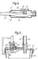
- FIG. 4 there is shown an alternative suction control 43' and valve 100' on the container 1'.
- the control lumen 41' of the suction tubing 42' is connected to a conduit 46' which opens through an orifice 47' without the interruption of any valve.
- the surface of the casing 44' around the orifice 47' is provided with a shallow concave recess 56' on which the user's finger or thumb is rested to cover the orifice.
- the valve 100' is similar to that shown in Figure 2 and differs only in the construction the valve member 105' and its mode of operation.
- valve member 105' differs from the earlier described valve member 105 in that its through aperture 108' is located at the left-hand end of the valve member so that the bore 103' is closed when the valve member 105' is located at the left-hand end of the recess 104'.
- the right-hand end of the valve recess 104' is close to atmospheric pressure; the spring 107' is in its expanded state, forcing the valve member 105' to the left-hand end of the recess 104'.
- the bore 103' is, therefore, blocked and the vacuum pump is isolated from the container 1'.
- the vacuum pump 2 When the user places his finger or thumb on the recess 56' of the suction control 43', it covers the orifice 47' and prevents air entering the control lumen 41'. This allows the vacuum pump 2 to reduce the pressure at the right-hand end of the valve recess 104' which in turn causes the valve member 105' to be displaced to the right along the recess, compressing the spring 107'. In its right-hand position, the aperture 108' in the valve member 105' is aligned with the bore 103' so that the valve 100' is opened and the vacuum pump is connected to the interior of the container 1'.
- valves that are completely sealed against the escape of liquid.
- a valve could take the form of a continuous fluid passageway that is deformable to prevent flow through it.
- the suction control could itself include a valve that prevents flow into the suction tube assembly, which in this arrangement need only have a single bore.
- the valve could, for example, be a spool valve or a pinch valve that opens and closes the passage along the suction lumen at the suction control itself.
- the container may take various different forms.
- the container might have a flexible liner 110' such as of the kind described in GB 2207709 or US 3,780,738 and as illustrated in Figure 5.
- the inlet 11' of the cap assembly 13' communicates with the interior of the liner 110' whereas the outlet 10' communicates with the space in the container 1' outside the liner 110'.
- the cap assembly 13' with the liner 110' attached can be disposed of and the vessel reused.
- the outlet may be provided with a safety valve to prevent over-filling, and a filter to prevent passage of airborne bacterial or aerosol droplets to the vacuum pump.
Applications Claiming Priority (2)
| Application Number | Priority Date | Filing Date | Title |
|---|---|---|---|
| US965843 | 1992-10-23 | ||
| US07/965,843 US5419769A (en) | 1992-10-23 | 1992-10-23 | Suction systems |
Publications (3)
| Publication Number | Publication Date |
|---|---|
| EP0599472A2 true EP0599472A2 (fr) | 1994-06-01 |
| EP0599472A3 EP0599472A3 (fr) | 1995-04-05 |
| EP0599472B1 EP0599472B1 (fr) | 1999-06-23 |
Family
ID=25510580
Family Applications (1)
| Application Number | Title | Priority Date | Filing Date |
|---|---|---|---|
| EP93308086A Expired - Lifetime EP0599472B1 (fr) | 1992-10-23 | 1993-10-11 | Systèmes de succion |
Country Status (11)
| Country | Link |
|---|---|
| US (1) | US5419769A (fr) |
| EP (1) | EP0599472B1 (fr) |
| JP (1) | JPH078552A (fr) |
| AU (1) | AU669214B2 (fr) |
| CA (1) | CA2108709A1 (fr) |
| DE (1) | DE69325432T2 (fr) |
| DK (1) | DK0599472T3 (fr) |
| ES (1) | ES2132196T3 (fr) |
| GB (1) | GB2271721B (fr) |
| IL (1) | IL107279A (fr) |
| ZA (1) | ZA937819B (fr) |
Cited By (4)
| Publication number | Priority date | Publication date | Assignee | Title |
|---|---|---|---|---|
| US8202262B2 (en) | 1994-08-22 | 2012-06-19 | Kci Licensing, Inc. | Wound therapy device and related methods |
| US8425489B2 (en) | 2009-05-08 | 2013-04-23 | Medela Holding Ag | Drainage tube device and coupling unit |
| CN108553697A (zh) * | 2018-04-25 | 2018-09-21 | 刘晓君 | 一种肝胆外科专用引流护理装置 |
| US10099027B2 (en) | 2014-01-24 | 2018-10-16 | Cole Research & Design | Oral suction device |
Families Citing this family (66)
| Publication number | Priority date | Publication date | Assignee | Title |
|---|---|---|---|---|
| IE69360B1 (en) * | 1993-07-01 | 1996-09-04 | Abbott Lab | Gelling treatment for suction drainage system |
| US5921970A (en) * | 1996-03-08 | 1999-07-13 | Vandenberg; James T. | Large variable diameter medical suction system |
| US5665080A (en) * | 1996-03-08 | 1997-09-09 | Vandenberg; James T. | Oropharyneal suctioning device |
| US6331172B1 (en) | 1997-04-14 | 2001-12-18 | Baxter International Inc. | Applicator for dispensing measured quantities with use of controlled suction |
| US5971956A (en) * | 1997-04-15 | 1999-10-26 | Biosurgical Corporation | Medical suctioning apparatus and methods of use |
| EP0984812B1 (fr) | 1997-04-14 | 2011-01-19 | Baxter International Inc. | Applicateur de fluide destine a distribuer des quantites mesurees a l'aide d'une aspiration commandee |
| US6017493A (en) | 1997-09-26 | 2000-01-25 | Baxter International Inc. | Vacuum-assisted venous drainage reservoir for CPB systems |
| US6918887B1 (en) | 1999-02-17 | 2005-07-19 | Medtronic, Inc. | Venous filter for assisted venous return |
| US6280415B1 (en) | 1999-03-10 | 2001-08-28 | W. Dudley Johnson | Tissue traction device |
| AU5298000A (en) | 1999-05-26 | 2000-12-12 | Scimed Life Systems, Inc. | A suction device for an endoscope |
| DK174620B1 (da) * | 2000-04-06 | 2003-07-28 | Maersk Medical As | En ventilanordning |
| EP1272244B9 (fr) * | 2000-04-06 | 2004-10-20 | Unomedical a/s | Agencement de couplage |
| ES2293974T3 (es) | 2000-04-06 | 2008-04-01 | Unomedical A/S | Distribuidor. |
| US6517531B2 (en) * | 2001-04-27 | 2003-02-11 | Scimed Life Systems, Inc. | Medical suction device |
| US7066917B2 (en) * | 2001-10-05 | 2006-06-27 | Talamonti Anthony R | Oral gastric lavage kit with matched aspiration stream apertures |
| US6648862B2 (en) * | 2001-11-20 | 2003-11-18 | Spheric Products, Ltd. | Personally portable vacuum desiccator |
| US6712799B2 (en) | 2001-11-27 | 2004-03-30 | Datex-Ohmada, Inc. | Disposable water seal for thoracic regulators |
| US7201870B2 (en) * | 2003-01-14 | 2007-04-10 | Medtronic, Inc. | Active air removal system operating modes of an extracorporeal blood circuit |
| US7198751B2 (en) * | 2003-01-14 | 2007-04-03 | Medtronic, Inc. | Disposable, integrated, extracorporeal blood circuit |
| US7189352B2 (en) * | 2003-01-14 | 2007-03-13 | Medtronic, Inc. | Extracorporeal blood circuit priming system and method |
| US7335334B2 (en) * | 2003-01-14 | 2008-02-26 | Medtronic, Inc. | Active air removal from an extracorporeal blood circuit |
| US7204958B2 (en) * | 2003-01-14 | 2007-04-17 | Medtronic, Inc. | Extracorporeal blood circuit air removal system and method |
| US20050065484A1 (en) * | 2003-09-10 | 2005-03-24 | Watson Richard L. | Wound healing apparatus with bioabsorbable material and suction tubes |
| US7613523B2 (en) * | 2003-12-11 | 2009-11-03 | Apsara Medical Corporation | Aesthetic thermal sculpting of skin |
| US7790945B1 (en) | 2004-04-05 | 2010-09-07 | Kci Licensing, Inc. | Wound dressing with absorption and suction capabilities |
| US20080125750A1 (en) * | 2006-09-27 | 2008-05-29 | Henning Arthur Gaissert | Medical catheter removal |
| US7967509B2 (en) | 2007-06-15 | 2011-06-28 | S.C. Johnson & Son, Inc. | Pouch with a valve |
| AU2008310622B2 (en) * | 2007-10-11 | 2014-01-09 | Solventum Intellectual Properties Company | Closed incision negative pressure wound therapy device and methods of use |
| GB2455962A (en) | 2007-12-24 | 2009-07-01 | Ethicon Inc | Reinforced adhesive backing sheet, for plaster |
| US8192182B2 (en) * | 2008-01-09 | 2012-06-05 | S.C. Johnson Home Storage, Inc. | Manual evacuation system |
| KR101608548B1 (ko) | 2008-03-05 | 2016-04-01 | 케이씨아이 라이센싱 인코포레이티드 | 조직 부위에 감압을 가하고,조직 부위로부터 유체를 수집 및 저장하는 드레싱 및 방법 |
| GB0914557D0 (en) | 2009-08-20 | 2009-09-30 | Smiths Medical Int Ltd | Ventilation and suction systems and assemblies |
| US8814842B2 (en) * | 2010-03-16 | 2014-08-26 | Kci Licensing, Inc. | Delivery-and-fluid-storage bridges for use with reduced-pressure systems |
| GB2488749A (en) | 2011-01-31 | 2012-09-12 | Systagenix Wound Man Ip Co Bv | Laminated silicone coated wound dressing |
| GB201106491D0 (en) | 2011-04-15 | 2011-06-01 | Systagenix Wound Man Ip Co Bv | Patterened silicone coating |
| DE102011052196B4 (de) * | 2011-07-27 | 2017-06-08 | MAQUET GmbH | Vorrichtung zum Absaugen von Flüssigkeiten und/oder Partikeln aus Körperöffnungen |
| US9861532B2 (en) | 2011-12-16 | 2018-01-09 | Kci Licensing, Inc. | Releasable medical drapes |
| US10940047B2 (en) | 2011-12-16 | 2021-03-09 | Kci Licensing, Inc. | Sealing systems and methods employing a hybrid switchable drape |
| US9402969B2 (en) * | 2012-09-26 | 2016-08-02 | Ulvac Kiko, Inc. | Sputum aspirating apparatus, artificial ventilation system including a sputum aspirating apparatus, and method for operating a sputum aspirating apparatus |
| SG11201503860RA (en) | 2012-11-16 | 2015-06-29 | Kci Licensing Inc | Medical drape with pattern adhesive layers and method of manufacturing same |
| GB201222770D0 (en) | 2012-12-18 | 2013-01-30 | Systagenix Wound Man Ip Co Bv | Wound dressing with adhesive margin |
| WO2015030963A1 (fr) | 2013-08-26 | 2015-03-05 | Kci Licensing, Inc. | Interface de pansement avec caractéristique de contrôle de l'humidité et fonction d'étanchéité |
| EP3062753B1 (fr) | 2013-10-28 | 2018-11-21 | KCI Licensing, Inc. | Ruban d'étanchéité hybride |
| CN110652396B (zh) | 2013-10-30 | 2021-11-23 | 3M创新知识产权公司 | 具有不同大小的穿孔的敷件 |
| EP3513773A1 (fr) | 2013-10-30 | 2019-07-24 | KCI Licensing, Inc. | Système d'absorption et de dissipation d'un condensat |
| US9956120B2 (en) | 2013-10-30 | 2018-05-01 | Kci Licensing, Inc. | Dressing with sealing and retention interface |
| EP3744361A1 (fr) | 2013-10-30 | 2020-12-02 | KCI Licensing, Inc. | Conduit et système absorbants |
| CA2940730C (fr) | 2014-02-28 | 2022-07-26 | Kci Licensing, Inc. | Drap hybride ayant une maille perforee recouverte de gel |
| US11026844B2 (en) | 2014-03-03 | 2021-06-08 | Kci Licensing, Inc. | Low profile flexible pressure transmission conduit |
| US10406266B2 (en) | 2014-05-02 | 2019-09-10 | Kci Licensing, Inc. | Fluid storage devices, systems, and methods |
| EP3281616B1 (fr) | 2014-06-05 | 2020-01-01 | KCI Licensing, Inc. | Pansement ayant des caractéristiques d'acquisition et de distribution de fluide |
| US10828051B2 (en) * | 2014-07-28 | 2020-11-10 | Shaw P. Wan | Suction evacuation device |
| US10828050B2 (en) * | 2014-07-28 | 2020-11-10 | Shaw P. Wan | Suction evacuation device |
| US10398604B2 (en) | 2014-12-17 | 2019-09-03 | Kci Licensing, Inc. | Dressing with offloading capability |
| US11246975B2 (en) | 2015-05-08 | 2022-02-15 | Kci Licensing, Inc. | Low acuity dressing with integral pump |
| US11071849B2 (en) | 2015-08-18 | 2021-07-27 | B. Braun Melsungen Ag | Catheter devices with valves and related methods |
| EP3344205B1 (fr) | 2015-09-01 | 2020-09-30 | KCI Licensing, Inc. | Pansement présentant une force d'apposition accrue |
| EP3349807B1 (fr) | 2015-09-17 | 2021-02-24 | 3M Innovative Properties Company | Revêtement adhésif de silicone et d'acrylique hybride destiné à être utilisé dans le traitement de plaies |
| US11944329B2 (en) * | 2017-01-12 | 2024-04-02 | Well Lead Co, LTD | Suction evacuation device |
| GB201717237D0 (en) | 2017-10-20 | 2017-12-06 | Smiths Medical International Ltd | Suction catheter assemblies |
| US11850377B2 (en) | 2018-12-17 | 2023-12-26 | B. Braun Melsungen Ag | Catheter assemblies and related methods |
| GB201902868D0 (en) | 2019-03-02 | 2019-04-17 | Smiths Medical International Ltd | Suction catheter assemblies and assemblies including a suction catheter assembly |
| GB201915251D0 (en) | 2019-10-22 | 2019-12-04 | Smiths Medical International Ltd | Connectors and assemblies |
| GB202006539D0 (en) | 2020-05-04 | 2020-06-17 | Smiths Medical International Ltd | Closed-system suction catheter assemblies |
| GB202011662D0 (en) | 2020-07-28 | 2020-09-09 | Smiths Medical International Ltd | Closed-system suction catheter |
| WO2022238668A1 (fr) | 2021-05-10 | 2022-11-17 | Smiths Medical International Limited | Ensembles cathéter d'aspiration |
Citations (2)
| Publication number | Priority date | Publication date | Assignee | Title |
|---|---|---|---|---|
| US4062360A (en) * | 1976-04-02 | 1977-12-13 | Bentley Laboratories, Inc. | Atraumatic fluid handling method and apparatus |
| US4850350A (en) * | 1986-06-23 | 1989-07-25 | Sheridan Catheter Corp. | Closed system combined suction and ventilation devices |
Family Cites Families (13)
| Publication number | Priority date | Publication date | Assignee | Title |
|---|---|---|---|---|
| US3780738A (en) * | 1971-12-08 | 1973-12-25 | Deaton Medical Co | Method and apparatus of medical suction |
| US3911919A (en) * | 1974-06-06 | 1975-10-14 | Concord Lab | Suction catheter |
| US3991762A (en) * | 1974-09-30 | 1976-11-16 | Radford F Richard | Aspirating device for patient ventilation apparatus |
| US4036232A (en) * | 1976-04-19 | 1977-07-19 | Abbott Laboratories | Aspiration device |
| US4430084A (en) * | 1980-01-21 | 1984-02-07 | American Hospital Supply Corp. | Method for pre-use storage of a medical receptacle |
| US4502503A (en) * | 1982-02-24 | 1985-03-05 | Anchor/Darling Valve Company | Vacuum breaker valve with internally balanced disc |
| DE3309918C2 (de) * | 1982-03-29 | 1994-09-01 | Barry Oliver Weightman | Saug- und Spülvorrichtung |
| DE3309916C2 (de) * | 1982-03-29 | 1993-12-09 | Smiths Industries Plc | Saug- und Spülvorrichtung |
| US4468216A (en) * | 1982-05-20 | 1984-08-28 | Rudolph Muto | Irrigation suction catheter |
| DE3405403A1 (de) * | 1984-02-15 | 1985-08-22 | Stöckert Instrumente GmbH, 8000 München | Chirurgische saugeranordnung |
| US4569344A (en) * | 1984-07-23 | 1986-02-11 | Ballard Medical Products | Aspirating/ventilating apparatus and method |
| GB2207709A (en) * | 1987-07-28 | 1989-02-08 | Clinimed Ltd | Fluid collection and transportation device |
| US5236425A (en) * | 1990-08-29 | 1993-08-17 | Bioresearch, Inc. | Self-adjusting suction regulator |
-
1992
- 1992-10-23 US US07/965,843 patent/US5419769A/en not_active Expired - Lifetime
-
1993
- 1993-10-11 DK DK93308086T patent/DK0599472T3/da active
- 1993-10-11 EP EP93308086A patent/EP0599472B1/fr not_active Expired - Lifetime
- 1993-10-11 ES ES93308086T patent/ES2132196T3/es not_active Expired - Lifetime
- 1993-10-11 DE DE69325432T patent/DE69325432T2/de not_active Expired - Fee Related
- 1993-10-11 GB GB9320903A patent/GB2271721B/en not_active Expired - Fee Related
- 1993-10-14 IL IL107279A patent/IL107279A/xx not_active IP Right Cessation
- 1993-10-19 CA CA002108709A patent/CA2108709A1/fr not_active Abandoned
- 1993-10-20 AU AU49105/93A patent/AU669214B2/en not_active Ceased
- 1993-10-21 ZA ZA937819A patent/ZA937819B/xx unknown
- 1993-10-21 JP JP5263744A patent/JPH078552A/ja active Pending
Patent Citations (2)
| Publication number | Priority date | Publication date | Assignee | Title |
|---|---|---|---|---|
| US4062360A (en) * | 1976-04-02 | 1977-12-13 | Bentley Laboratories, Inc. | Atraumatic fluid handling method and apparatus |
| US4850350A (en) * | 1986-06-23 | 1989-07-25 | Sheridan Catheter Corp. | Closed system combined suction and ventilation devices |
Cited By (4)
| Publication number | Priority date | Publication date | Assignee | Title |
|---|---|---|---|---|
| US8202262B2 (en) | 1994-08-22 | 2012-06-19 | Kci Licensing, Inc. | Wound therapy device and related methods |
| US8425489B2 (en) | 2009-05-08 | 2013-04-23 | Medela Holding Ag | Drainage tube device and coupling unit |
| US10099027B2 (en) | 2014-01-24 | 2018-10-16 | Cole Research & Design | Oral suction device |
| CN108553697A (zh) * | 2018-04-25 | 2018-09-21 | 刘晓君 | 一种肝胆外科专用引流护理装置 |
Also Published As
| Publication number | Publication date |
|---|---|
| AU669214B2 (en) | 1996-05-30 |
| CA2108709A1 (fr) | 1994-04-24 |
| ZA937819B (en) | 1994-05-19 |
| ES2132196T3 (es) | 1999-08-16 |
| GB2271721B (en) | 1996-07-10 |
| EP0599472A3 (fr) | 1995-04-05 |
| US5419769A (en) | 1995-05-30 |
| DE69325432T2 (de) | 1999-10-21 |
| IL107279A (en) | 1997-09-30 |
| GB2271721A (en) | 1994-04-27 |
| EP0599472B1 (fr) | 1999-06-23 |
| AU4910593A (en) | 1994-05-05 |
| DE69325432D1 (de) | 1999-07-29 |
| DK0599472T3 (da) | 1999-11-22 |
| IL107279A0 (en) | 1994-01-25 |
| JPH078552A (ja) | 1995-01-13 |
| GB9320903D0 (en) | 1993-12-01 |
Similar Documents
| Publication | Publication Date | Title |
|---|---|---|
| EP0599472B1 (fr) | Systèmes de succion | |
| US4872579A (en) | Aspirating/ventilating apparatus and method | |
| US5215522A (en) | Single use medical aspirating device and method | |
| US5279549A (en) | Closed ventilation and suction catheter system | |
| US5277177A (en) | Single use medical aspirating device and method | |
| US4836199A (en) | Aspirating/ventilating apparatus and method | |
| US5269768A (en) | Valved suction catheter | |
| US5664564A (en) | Aspirating/ventilating apparatus and method | |
| US4696296A (en) | Aspirating/ventilating apparatus | |
| US5220916A (en) | Tracheal suction catheter | |
| US5300043A (en) | Suction catheter valve | |
| US5460613A (en) | Suction catheter assemblies | |
| US5139018A (en) | Patient ventilating apparatus with aspirating catheter | |
| US5325850A (en) | Suction catheter assemblies | |
| US5433195A (en) | Respiratory support system | |
| CA1128395A (fr) | Accessoire pour aspirateur tracheal | |
| US5368017A (en) | Apparatus for ventilating and aspirating | |
| US6923184B1 (en) | Suction system with high efficiency suction control valve | |
| AU2005228826B2 (en) | A patient ventilating and aspirating system | |
| US5134996A (en) | Inspiration and expiration indicator for a suction catheter | |
| EP0263450B1 (fr) | Dispositif d'aspiration | |
| US5377672A (en) | Suction control valve | |
| CN112336414A (zh) | 具有文丘里抽吸的血栓切除术 | |
| EP0595499B1 (fr) | Assemblages de cathéters de succion | |
| CA2058893C (fr) | Catheter pour succion tracheale |
Legal Events
| Date | Code | Title | Description |
|---|---|---|---|
| PUAI | Public reference made under article 153(3) epc to a published international application that has entered the european phase |
Free format text: ORIGINAL CODE: 0009012 |
|
| AK | Designated contracting states |
Kind code of ref document: A2 Designated state(s): DE DK ES FR GR IE IT NL SE |
|
| PUAL | Search report despatched |
Free format text: ORIGINAL CODE: 0009013 |
|
| AK | Designated contracting states |
Kind code of ref document: A3 Designated state(s): DE DK ES FR GR IE IT NL SE |
|
| 17P | Request for examination filed |
Effective date: 19950801 |
|
| 17Q | First examination report despatched |
Effective date: 19970116 |
|
| RAP1 | Party data changed (applicant data changed or rights of an application transferred) |
Owner name: SIMS PORTEX, INC. |
|
| GRAG | Despatch of communication of intention to grant |
Free format text: ORIGINAL CODE: EPIDOS AGRA |
|
| GRAG | Despatch of communication of intention to grant |
Free format text: ORIGINAL CODE: EPIDOS AGRA |
|
| GRAH | Despatch of communication of intention to grant a patent |
Free format text: ORIGINAL CODE: EPIDOS IGRA |
|
| GRAH | Despatch of communication of intention to grant a patent |
Free format text: ORIGINAL CODE: EPIDOS IGRA |
|
| GRAA | (expected) grant |
Free format text: ORIGINAL CODE: 0009210 |
|
| AK | Designated contracting states |
Kind code of ref document: B1 Designated state(s): DE DK ES FR GR IE IT NL SE |
|
| PG25 | Lapsed in a contracting state [announced via postgrant information from national office to epo] |
Ref country code: SE Free format text: THE PATENT HAS BEEN ANNULLED BY A DECISION OF A NATIONAL AUTHORITY Effective date: 19990623 Ref country code: GR Free format text: LAPSE BECAUSE OF NON-PAYMENT OF DUE FEES Effective date: 19990623 |
|
| REF | Corresponds to: |
Ref document number: 69325432 Country of ref document: DE Date of ref document: 19990729 |
|
| ET | Fr: translation filed | ||
| REG | Reference to a national code |
Ref country code: ES Ref legal event code: FG2A Ref document number: 2132196 Country of ref document: ES Kind code of ref document: T3 |
|
| REG | Reference to a national code |
Ref country code: IE Ref legal event code: FG4D |
|
| ITF | It: translation for a ep patent filed |
Owner name: ING. ZINI MARANESI & C. S.R.L. |
|
| PG25 | Lapsed in a contracting state [announced via postgrant information from national office to epo] |
Ref country code: IE Free format text: LAPSE BECAUSE OF NON-PAYMENT OF DUE FEES Effective date: 19991011 Ref country code: DK Free format text: LAPSE BECAUSE OF NON-PAYMENT OF DUE FEES Effective date: 19991011 |
|
| PG25 | Lapsed in a contracting state [announced via postgrant information from national office to epo] |
Ref country code: ES Free format text: LAPSE BECAUSE OF NON-PAYMENT OF DUE FEES Effective date: 19991012 |
|
| PGFP | Annual fee paid to national office [announced via postgrant information from national office to epo] |
Ref country code: FR Payment date: 19991026 Year of fee payment: 7 |
|
| REG | Reference to a national code |
Ref country code: DK Ref legal event code: T3 |
|
| PGFP | Annual fee paid to national office [announced via postgrant information from national office to epo] |
Ref country code: DE Payment date: 19991206 Year of fee payment: 7 |
|
| PLBE | No opposition filed within time limit |
Free format text: ORIGINAL CODE: 0009261 |
|
| STAA | Information on the status of an ep patent application or granted ep patent |
Free format text: STATUS: NO OPPOSITION FILED WITHIN TIME LIMIT |
|
| PG25 | Lapsed in a contracting state [announced via postgrant information from national office to epo] |
Ref country code: NL Free format text: LAPSE BECAUSE OF NON-PAYMENT OF DUE FEES Effective date: 20000501 |
|
| 26N | No opposition filed | ||
| EUG | Se: european patent has lapsed |
Ref document number: 93308086.3 |
|
| NLV4 | Nl: lapsed or anulled due to non-payment of the annual fee |
Effective date: 20000501 |
|
| REG | Reference to a national code |
Ref country code: IE Ref legal event code: MM4A |
|
| PG25 | Lapsed in a contracting state [announced via postgrant information from national office to epo] |
Ref country code: FR Free format text: LAPSE BECAUSE OF NON-PAYMENT OF DUE FEES Effective date: 20010629 |
|
| PG25 | Lapsed in a contracting state [announced via postgrant information from national office to epo] |
Ref country code: DE Free format text: LAPSE BECAUSE OF NON-PAYMENT OF DUE FEES Effective date: 20010703 |
|
| REG | Reference to a national code |
Ref country code: FR Ref legal event code: ST |
|
| REG | Reference to a national code |
Ref country code: DK Ref legal event code: EBP |
|
| REG | Reference to a national code |
Ref country code: ES Ref legal event code: FD2A Effective date: 20001113 |
|
| PG25 | Lapsed in a contracting state [announced via postgrant information from national office to epo] |
Ref country code: IT Free format text: LAPSE BECAUSE OF NON-PAYMENT OF DUE FEES;WARNING: LAPSES OF ITALIAN PATENTS WITH EFFECTIVE DATE BEFORE 2007 MAY HAVE OCCURRED AT ANY TIME BEFORE 2007. THE CORRECT EFFECTIVE DATE MAY BE DIFFERENT FROM THE ONE RECORDED. Effective date: 20051011 |