EP0599362B1 - Apparatus for positively preventing misengagement of multipoint connector elements - Google Patents
Apparatus for positively preventing misengagement of multipoint connector elements Download PDFInfo
- Publication number
- EP0599362B1 EP0599362B1 EP93202982A EP93202982A EP0599362B1 EP 0599362 B1 EP0599362 B1 EP 0599362B1 EP 93202982 A EP93202982 A EP 93202982A EP 93202982 A EP93202982 A EP 93202982A EP 0599362 B1 EP0599362 B1 EP 0599362B1
- Authority
- EP
- European Patent Office
- Prior art keywords
- pivot
- multipoint connector
- stepped guide
- connector elements
- guide surface
- Prior art date
- Legal status (The legal status is an assumption and is not a legal conclusion. Google has not performed a legal analysis and makes no representation as to the accuracy of the status listed.)
- Expired - Lifetime
Links
Images






Classifications
-
- H—ELECTRICITY
- H01—ELECTRIC ELEMENTS
- H01R—ELECTRICALLY-CONDUCTIVE CONNECTIONS; STRUCTURAL ASSOCIATIONS OF A PLURALITY OF MUTUALLY-INSULATED ELECTRICAL CONNECTING ELEMENTS; COUPLING DEVICES; CURRENT COLLECTORS
- H01R13/00—Details of coupling devices of the kinds covered by groups H01R12/70 or H01R24/00 - H01R33/00
- H01R13/62—Means for facilitating engagement or disengagement of coupling parts or for holding them in engagement
- H01R13/629—Additional means for facilitating engagement or disengagement of coupling parts, e.g. aligning or guiding means, levers, gas pressure electrical locking indicators, manufacturing tolerances
- H01R13/631—Additional means for facilitating engagement or disengagement of coupling parts, e.g. aligning or guiding means, levers, gas pressure electrical locking indicators, manufacturing tolerances for engagement only
Definitions
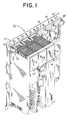
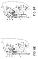
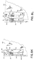
- the three PLC modules 14 , 14' , 14'' are supported by the mounting assembly 12 through a simple pivot pin and pivot slot arrangement.
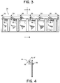
- Each PLC module 14 , 14' , 14 " has two associated pivot pins 20 and the mounting assembly 12 provides a number of pivot slots 18 , 18' , each of which supports at least one of the PLC module pivot pins 20 .
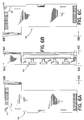
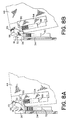
- the pivot slots 18 , 18' of the mounting assembly 12 support the pivot pins 20 of the PLC modules 14 , 14' , 14 ", and hence the PLC modules 14 , 14' , 14" themselves.
- the outer pivot slots 18' provide approximately one half the slot area that the inner pivot slots 18 provide since these outer pivot slots 18' are only required to support a single pivot pin 20 .
Landscapes
- Details Of Connecting Devices For Male And Female Coupling (AREA)
- Mounting Of Printed Circuit Boards And The Like (AREA)
- Earth Drilling (AREA)
- Variable-Direction Aerials And Aerial Arrays (AREA)
- Use Of Switch Circuits For Exchanges And Methods Of Control Of Multiplex Exchanges (AREA)
- Coupling Device And Connection With Printed Circuit (AREA)
Abstract
Description
Claims (20)
- An apparatus for positively preventing misengagement of multipoint connector elements, said apparatus comprising:characterised in that:a plug element (54) of a multipoint connector;a receptacle element (34) of a multipoint connector, wherein said plug element (54) and said receptacle element (34) can be engaged when properly aligned;first alignment means associated with said multipoint connector elements (54, 34) for providing engagement alignment between said plug element (54) and said receptacle element (34),second alignment means associated with said multipoint connector elements (54, 34) for providing engagement alignment between said plug element (54) and said receptacle element (34),said first alignment means includes at least one pivot pin (20) having an associated stepped guide surface (50); and in thatsaid second alignment means includes at least one pivot slot (18) having an associated stepped guide surface (32), the arrangement being such that each said stepped guide surface (50) associated with a respective one of said pivot pins (20) is able to be concentrically mated with a corresponding stepped guide surface (50) associated with a corresponding one of said pivot slots (18), so as to positively prevent misengagement of said multipoint connector elements (54, 34) unless said pivot pin (20) is fully seated in said pivot slot (18) thus ensuring said multipoint connector elements are properly aligned.
- Apparatus as claimed in claim 1, characterised in that each said stepped guide surface (50) associated with a respective one of said pivot pins (20) has an associated step, in that each said stepped guide surface (32) associated with a respective one of said pivot slots (18) has an associated step, and in that said concentrically matable stepped guide surfaces (32, 50) are adapted to act to positively prevent misengagement of said multipoint connector elements (54, 34) by having said steps abut against each other.
- Apparatus as claimed in claim 1 or claim 2, characterised in that said concentrically matable stepped guide surfaces (32, 50) provide said multipoint connector elements with an angular engagement path when said pivot pin (20) is fully seated in said pivot slot (18).
- Apparatus as claimed in claim 3, characterised in that said plug element (54) has a plurality of pin contacts (68), in that each receptacle element (34) has a like plurality of socket contacts (70), and in that said angular engagement path allows electrical contact between said pin contacts (68) and said socket contacts (70) in sequential order.
- Apparatus as claimed in any preceding claim, characterised in that said concentrically matable stepped guide surfaces (32, 50) provide said multipoint connector elements (54, 34) with an angular disengagement path when said pivot pin (20) is fully seated in said pivot slot (18).
- Apparatus as claimed in any preceding claim, characterised in that said plug element (54) has a plurality of pin contacts (68), in that said receptacle element (34) has a like plurality of socket contacts (70), and in that said angular disengagement path allows electrical contact to be broken between said pin contacts (68) and said socket contacts (70) in sequential order.
- Apparatus as claimed in any preceding claim, characterised in that said first alignment means comprises a housing (44) dimensioned for mounting one of said multipoint connector elements (54), and in that said housing (44) provides two pivot pins (20) for the first alignment means and two associated stepped guide surfaces (50) for two pivot slots (18) of the second alignment means.
- Apparatus as claimed in claim 7, characterised in that said housing (44) is supported by said second alignment means.
- Apparatus as claimed in claim 7 or claim 8, characterised in that said housing (44) is dimensioned for mounting said plug element (54).
- Apparatus as claimed in claim 7, claim 8 or claim 9, characterised in that said housing (44) is dimensioned for mounting said receptacle element (34).
- Apparatus as claimed in any preceding claim, characterised in that said second alignment means comprises a mounting assembly (12) that maintains one of said multipoint connector elements (34), and in that said mounting assembly (12) provides two pivot slots for the first alignment means and two associated stepped guide surfaces for two pivot slots (18) of the second alignment means.
- Apparatus as claimed in claim 11, characterised in that said mounting assembly (12) supports said first alignment means.
- Apparatus as claimed in claim 11 or claim 12, characterised in that said mounting assembly (12) maintains said receptacle element (34).
- Apparatus as claimed in claim 11, claim 12 or claim 13, characterised in that said mounting assembly (12) maintains said plug element (54).
- A modular programmable logic controller (PLC) system (10) having a mounting assembly (12) and an PLC module (14), wherein said mounting assembly has an associated receptacle element (34) ofa multipoint connector and said PLC module has an associated plug element (54) of a multipoint connector, and wherein said mounting assembly (12) and said PLC module (14) are formed to interact in a manner that positively prevents misengagement of said multipoint connector elements (34, 54),
characterised in that:said mounting assembly (12) has a pivot slot (18) with an associated stepped guide surface (32), said mounting assembly also has an associated receptacle element (34) of a multipoint connector; and in thatthe PLC module (14) has a pivot pin (20) with an associated stepped guide surface (50), said PLC module also has an associated plug element (54) of a multipoint connector, such that said pivot slot (18) and said stepped guide surface (32) of said mounting assembly (12) corresponds with said pivot pin (20) and said stepped guide surface (50) of said PLC module (14) so as to positively prevent misengagement of said multipoint connector elements (34, 54). - A system as claimed in claim 15, characterised in that each said stepped guide surface (50) associated with a respective one of said pivot pins (20) has an associated step, in that each said stepped guide surface (32) associated with a respective one of said pivot slots (18) has an associated step, and in that said pivot slot (18) and said stepped guide surface (32) of said mounting assembly correspond with said pivot pin (20) and said stepped guide surface (50) of said PLC module by having said steps abut against each other prior to engagement of said multipoint connector elements (34, 54) unless said pivot pin (20) is fully seated in said pivot slot (18).
- A system as claimed in claim 15 or claim 16, characterised in that said stepped guide surfaces (32, 50) are able to be concentrically mated to provide said multipoint connector elements (34, 54) with an angular engagement path when said pivot pin (20) is fully seated in said pivot slot (18).
- A system as claimed in claim 15, claim 16 or claim 17, characterised in that said plug element (54) has a plurality of pin contacts (68), in that said receptacle element (34) has a like plurality of socket contacts (70), and in that said angular engagement path allows electrical contact between said pin contacts (68) and said socket contacts (70) in a sequential order.
- A system as claimed in any one of claims 15 to 18, characterised in that said stepped guide surfaces (32, 50) are able to be concentrically mated to provide said multipoint connector elements (34, 54) with an angular disengagement path when said pivot pin (20) is fully seated in said pivot slot (18).
- A system as claimed in any one of claims 15 to 19, characterised in that said plug element (54) has a plurality of pin contacts (68), in that said receptacle element (34) has a like plurality of socket contacts (70), and in that said angular disengagement path allows electrical contact to be broken between said pin contacts (68) and said socket contacts (70) in a sequential order.
Applications Claiming Priority (2)
| Application Number | Priority Date | Filing Date | Title |
|---|---|---|---|
| US07/980,573 US5302136A (en) | 1992-11-23 | 1992-11-23 | Apparatus for positively preventing misengagement of multipoint connector elements |
| US980573 | 1992-11-23 |
Publications (3)
| Publication Number | Publication Date |
|---|---|
| EP0599362A2 EP0599362A2 (en) | 1994-06-01 |
| EP0599362A3 EP0599362A3 (en) | 1995-11-29 |
| EP0599362B1 true EP0599362B1 (en) | 1998-09-23 |
Family
ID=25527674
Family Applications (1)
| Application Number | Title | Priority Date | Filing Date |
|---|---|---|---|
| EP93202982A Expired - Lifetime EP0599362B1 (en) | 1992-11-23 | 1993-10-26 | Apparatus for positively preventing misengagement of multipoint connector elements |
Country Status (5)
| Country | Link |
|---|---|
| US (1) | US5302136A (en) |
| EP (1) | EP0599362B1 (en) |
| JP (1) | JP3742663B2 (en) |
| AT (1) | ATE171570T1 (en) |
| DE (1) | DE69321196T2 (en) |
Families Citing this family (34)
| Publication number | Priority date | Publication date | Assignee | Title |
|---|---|---|---|---|
| US5601445A (en) * | 1995-03-13 | 1997-02-11 | Imed Corporation | Electrical and structural interconnector |
| JP3527812B2 (en) * | 1996-07-30 | 2004-05-17 | アルプス電気株式会社 | IC card connector |
| BR9603496A (en) * | 1996-08-21 | 1998-09-08 | Whitaker Corp | Electrical connector assembly |
| US5947748A (en) * | 1996-09-30 | 1999-09-07 | Siemens Energy & Automation, Inc. | Connector for programmable logic controller having modifiable termination therefor |
| US5751559A (en) * | 1996-10-08 | 1998-05-12 | International Business Machines Corporation | Apparatus for inserting PC cards having recessed guide paths with multiple levels in the guide paths |
| US6093042A (en) * | 1998-12-10 | 2000-07-25 | Berg Technology, Inc. | High density connector with low insertion force |
| US6406316B1 (en) | 1998-01-31 | 2002-06-18 | Fci Americas Technology, Inc. | Electrical connector with multiple housings |
| US6155860A (en) * | 1998-01-31 | 2000-12-05 | Berg Technology, Inc. | Socket for electrical component |
| JPH11283699A (en) * | 1998-03-31 | 1999-10-15 | Yazaki Corp | Connector structure |
| US6217360B1 (en) * | 1998-05-29 | 2001-04-17 | Paradyne Corporation | Connector lock |
| US6053760A (en) * | 1998-06-05 | 2000-04-25 | International Business Machines Corporation | Universal device for mounting circuit cards in a computer or like electrical machine |
| US6373712B1 (en) | 1998-06-05 | 2002-04-16 | International Business Machines Corporation | Device for inserting circuit cards into electrical machines |
| JP2000306620A (en) * | 1999-04-15 | 2000-11-02 | Internatl Business Mach Corp <Ibm> | Connector for connecting sub-card board, sub-card board, modem sub-card, and computer provided with the connector |
| FR2794564B1 (en) * | 1999-06-07 | 2002-02-08 | Enertec | DATA RECORDING DEVICE WITH HERMETIC, REMOVABLE, AND SUSPENDED CARTRIDGE |
| US6654255B2 (en) * | 1999-12-02 | 2003-11-25 | Adtran, Inc. | System for mounting data communication equipment |
| US6350141B1 (en) | 2000-05-30 | 2002-02-26 | Fci Americas Technology, Inc. | Connector frame for a high density electrical connector |
| FR2838875B1 (en) * | 2002-04-18 | 2004-08-27 | Dassault Aviat | METHOD FOR CONNECTING ELECTRICAL CONNECTORS AND CONNECTION BOX DESIGNED FOR THE IMPLEMENTATION OF THIS METHOD |
| FR2848029B1 (en) * | 2002-11-29 | 2005-03-04 | Schneider Electric Ind Sas | DEVICE FOR ELECTRICALLY CONNECTING A MODULAR ELECTRICAL APPARATUS TO A CONNECTING COMB OR THE LIKE |
| US20040206613A1 (en) * | 2003-04-17 | 2004-10-21 | Schneider Automation Inc. | Network tap system and method |
| US6896539B2 (en) * | 2003-06-30 | 2005-05-24 | Hewlett-Packard Development Company, L.P. | Pivot component coupled with first circuit board for control of relative alignment of first circuit board connection component with second circuit board connection component |
| DE102005047298B3 (en) * | 2005-09-30 | 2007-05-16 | Sirona Dental Systems Gmbh | Fastening device for a plug connection with two connecting parts, in particular for a dental treatment station |
| JP2008118772A (en) * | 2006-11-02 | 2008-05-22 | Yazaki Corp | Board connector |
| US7722377B2 (en) * | 2008-05-16 | 2010-05-25 | Moore Harold G | Power connection system |
| DE102010046990B4 (en) * | 2010-09-30 | 2012-05-03 | Phoenix Contact Gmbh & Co. Kg | Device for holding DIN rail module housings |
| US9287666B2 (en) * | 2011-05-03 | 2016-03-15 | Cardioinsight Technologies, Inc. | Electrical connector plug with key to avoid contact damage |
| DE102011110184A1 (en) * | 2011-08-09 | 2013-02-14 | Pilz Gmbh & Co. Kg | Modular control device |
| EP2648284A1 (en) * | 2012-04-02 | 2013-10-09 | Siemens Aktiengesellschaft | Front connector for an SPS component assembly |
| JP5614662B2 (en) * | 2012-10-26 | 2014-10-29 | 横河電機株式会社 | Input/Output Modules |
| CN203250925U (en) * | 2013-05-03 | 2013-10-23 | 泰科电子(上海)有限公司 | Connector Plugs and Connector Assemblies |
| US9640908B2 (en) * | 2015-01-05 | 2017-05-02 | Mizco International Inc. | Alignment apparatus and a method for manufacturing thereof |
| US10194553B1 (en) * | 2017-11-11 | 2019-01-29 | Rockwell Automation Asia Pacific Business Center Pte. Ltd. | Selectively installable and removable auxiliary wiring device for I/O module |
| US12177993B2 (en) | 2020-01-01 | 2024-12-24 | Selec Controls Private Limited | Modular and configurable electrical device group |
| US11171438B2 (en) * | 2020-04-09 | 2021-11-09 | Energy Services LLC | Unitized cable plug array for mobile power generation equipment |
| CN114552757A (en) * | 2020-11-24 | 2022-05-27 | 太阳能安吉科技有限公司 | Standby system, standby interface module and substrate |
Family Cites Families (14)
| Publication number | Priority date | Publication date | Assignee | Title |
|---|---|---|---|---|
| US2987693A (en) * | 1957-09-03 | 1961-06-06 | Itt | Electrical connector assembly |
| US3171704A (en) * | 1960-12-30 | 1965-03-02 | Int Harvester Co | Electrical connector |
| US3617985A (en) * | 1969-10-24 | 1971-11-02 | Motorola Inc | Accessory connector |
| US3668605A (en) * | 1970-08-10 | 1972-06-06 | North Electric Co | Multi-point program plug and receptacle connector arrangement having positive alignment prior to positive mating |
| US4151580A (en) * | 1977-11-21 | 1979-04-24 | Allen-Bradley Company | Circuit board assembly with disconnect arm |
| CA1096951A (en) * | 1978-02-03 | 1981-03-03 | Amp Incorporated | Polarised electrical connector |
| DE2810071C3 (en) * | 1978-03-08 | 1981-04-09 | Siemens AG, 1000 Berlin und 8000 München | Arrangement for fastening and wiring electrical devices |
| DE3310136A1 (en) * | 1983-03-21 | 1984-09-27 | Siemens AG, 1000 Berlin und 8000 München | CODABLE CONNECTOR |
| IN164043B (en) * | 1984-05-21 | 1988-12-31 | Siemens Ag | |
| DE3418844A1 (en) * | 1984-05-21 | 1985-11-21 | Siemens AG, 1000 Berlin und 8000 München | BOXED FLAT ASSEMBLY |
| DE3603750C3 (en) * | 1986-02-06 | 1996-10-17 | Siemens Ag | Automation device |
| FR2609215B1 (en) * | 1986-12-29 | 1993-01-08 | Wago Verwaltungs Gmbh | PLUG CONNECTION WITH REFERENCES |
| DE3711464C3 (en) * | 1987-04-04 | 1998-09-17 | Framatome Connectors Int | Electrical coupling device |
| US4869681A (en) * | 1987-08-28 | 1989-09-26 | Siemens Aktiengesellschaft | Front plug system with lagging end contact arrangement |
-
1992
- 1992-11-23 US US07/980,573 patent/US5302136A/en not_active Expired - Lifetime
-
1993
- 1993-08-23 JP JP22782093A patent/JP3742663B2/en not_active Expired - Lifetime
- 1993-10-26 DE DE69321196T patent/DE69321196T2/en not_active Expired - Lifetime
- 1993-10-26 AT AT93202982T patent/ATE171570T1/en not_active IP Right Cessation
- 1993-10-26 EP EP93202982A patent/EP0599362B1/en not_active Expired - Lifetime
Also Published As
| Publication number | Publication date |
|---|---|
| EP0599362A2 (en) | 1994-06-01 |
| EP0599362A3 (en) | 1995-11-29 |
| ATE171570T1 (en) | 1998-10-15 |
| JPH07297579A (en) | 1995-11-10 |
| DE69321196D1 (en) | 1998-10-29 |
| DE69321196T2 (en) | 1999-03-18 |
| US5302136A (en) | 1994-04-12 |
| JP3742663B2 (en) | 2006-02-08 |
Similar Documents
| Publication | Publication Date | Title |
|---|---|---|
| US5302136A (en) | Apparatus for positively preventing misengagement of multipoint connector elements | |
| US6540559B1 (en) | Connector with staggered contact pattern | |
| US5138679A (en) | Optical fiber connector with centering and floating alignment feature | |
| US7387517B2 (en) | Connector mounting structure | |
| KR950002037B1 (en) | Floating mounting means for electrical connector assembly | |
| US8951055B2 (en) | Electrical device with a plug-type connector and electrical plug-type connection | |
| US7762839B2 (en) | Patch panel assembly | |
| US5403207A (en) | Electrical connector with electrical component mounting structure | |
| JP5301725B2 (en) | Female connector assembly | |
| US20020160658A1 (en) | Electrical connector assembly for orthogonally mating circuit boards | |
| US5883998A (en) | Backplane connectors with separable electrical and optical connectors | |
| JPH03100504A (en) | Optical fiber connector assembly | |
| JPH05335055A (en) | Modular socket assembly | |
| US20060291784A1 (en) | Electro-optical communication system | |
| US10928027B2 (en) | Card edge connector for a lighting module | |
| US6302744B1 (en) | Connector system with polarizing key mechanism | |
| JPH1032060A (en) | Modular connector | |
| US5961335A (en) | Decentralized input/output module for a data bus | |
| JPH0246670A (en) | Wire harness connector holder | |
| US6761487B2 (en) | Adjustable and modular backplane assembly for providing a fiber-optics communication backplane | |
| US5607315A (en) | Connector for injector retention and electrical connection to a fuel rail | |
| US20020029898A1 (en) | Insulating body for a connector for the transmission of optical and electrical signals | |
| EP0817320A2 (en) | Connector | |
| US6190194B1 (en) | Attachment and connection structure of electrical equipment unit | |
| US20030036313A1 (en) | Plug connector with adapter |
Legal Events
| Date | Code | Title | Description |
|---|---|---|---|
| PUAI | Public reference made under article 153(3) epc to a published international application that has entered the european phase |
Free format text: ORIGINAL CODE: 0009012 |
|
| AK | Designated contracting states |
Kind code of ref document: A2 Designated state(s): AT BE CH DE DK ES FR GB GR IE IT LI LU MC NL PT SE |
|
| PUAL | Search report despatched |
Free format text: ORIGINAL CODE: 0009013 |
|
| AK | Designated contracting states |
Kind code of ref document: A3 Designated state(s): AT BE CH DE DK ES FR GB GR IE IT LI LU MC NL PT SE |
|
| 17P | Request for examination filed |
Effective date: 19960427 |
|
| 17Q | First examination report despatched |
Effective date: 19970218 |
|
| GRAG | Despatch of communication of intention to grant |
Free format text: ORIGINAL CODE: EPIDOS AGRA |
|
| RAP1 | Party data changed (applicant data changed or rights of an application transferred) |
Owner name: SCHNEIDER AUTOMATION INC. |
|
| GRAG | Despatch of communication of intention to grant |
Free format text: ORIGINAL CODE: EPIDOS AGRA |
|
| GRAH | Despatch of communication of intention to grant a patent |
Free format text: ORIGINAL CODE: EPIDOS IGRA |
|
| GRAH | Despatch of communication of intention to grant a patent |
Free format text: ORIGINAL CODE: EPIDOS IGRA |
|
| ITF | It: translation for a ep patent filed | ||
| GRAA | (expected) grant |
Free format text: ORIGINAL CODE: 0009210 |
|
| AK | Designated contracting states |
Kind code of ref document: B1 Designated state(s): AT BE CH DE DK ES FR GB GR IE IT LI LU MC NL PT SE |
|
| PG25 | Lapsed in a contracting state [announced via postgrant information from national office to epo] |
Ref country code: NL Free format text: LAPSE BECAUSE OF FAILURE TO SUBMIT A TRANSLATION OF THE DESCRIPTION OR TO PAY THE FEE WITHIN THE PRESCRIBED TIME-LIMIT Effective date: 19980923 Ref country code: LI Free format text: LAPSE BECAUSE OF FAILURE TO SUBMIT A TRANSLATION OF THE DESCRIPTION OR TO PAY THE FEE WITHIN THE PRESCRIBED TIME-LIMIT Effective date: 19980923 Ref country code: GR Free format text: LAPSE BECAUSE OF FAILURE TO SUBMIT A TRANSLATION OF THE DESCRIPTION OR TO PAY THE FEE WITHIN THE PRESCRIBED TIME-LIMIT Effective date: 19980923 Ref country code: ES Free format text: THE PATENT HAS BEEN ANNULLED BY A DECISION OF A NATIONAL AUTHORITY Effective date: 19980923 Ref country code: CH Free format text: LAPSE BECAUSE OF FAILURE TO SUBMIT A TRANSLATION OF THE DESCRIPTION OR TO PAY THE FEE WITHIN THE PRESCRIBED TIME-LIMIT Effective date: 19980923 Ref country code: AT Free format text: LAPSE BECAUSE OF FAILURE TO SUBMIT A TRANSLATION OF THE DESCRIPTION OR TO PAY THE FEE WITHIN THE PRESCRIBED TIME-LIMIT Effective date: 19980923 |
|
| REF | Corresponds to: |
Ref document number: 171570 Country of ref document: AT Date of ref document: 19981015 Kind code of ref document: T |
|
| REG | Reference to a national code |
Ref country code: CH Ref legal event code: EP |
|
| REF | Corresponds to: |
Ref document number: 69321196 Country of ref document: DE Date of ref document: 19981029 |
|
| PG25 | Lapsed in a contracting state [announced via postgrant information from national office to epo] |
Ref country code: IE Free format text: LAPSE BECAUSE OF NON-PAYMENT OF DUE FEES Effective date: 19981123 |
|
| ET | Fr: translation filed | ||
| REG | Reference to a national code |
Ref country code: IE Ref legal event code: FG4D |
|
| PG25 | Lapsed in a contracting state [announced via postgrant information from national office to epo] |
Ref country code: SE Free format text: LAPSE BECAUSE OF FAILURE TO SUBMIT A TRANSLATION OF THE DESCRIPTION OR TO PAY THE FEE WITHIN THE PRESCRIBED TIME-LIMIT Effective date: 19981223 Ref country code: PT Free format text: LAPSE BECAUSE OF FAILURE TO SUBMIT A TRANSLATION OF THE DESCRIPTION OR TO PAY THE FEE WITHIN THE PRESCRIBED TIME-LIMIT Effective date: 19981223 Ref country code: DK Free format text: LAPSE BECAUSE OF FAILURE TO SUBMIT A TRANSLATION OF THE DESCRIPTION OR TO PAY THE FEE WITHIN THE PRESCRIBED TIME-LIMIT Effective date: 19981223 |
|
| NLV1 | Nl: lapsed or annulled due to failure to fulfill the requirements of art. 29p and 29m of the patents act | ||
| REG | Reference to a national code |
Ref country code: CH Ref legal event code: PL |
|
| PG25 | Lapsed in a contracting state [announced via postgrant information from national office to epo] |
Ref country code: MC Free format text: LAPSE BECAUSE OF NON-PAYMENT OF DUE FEES Effective date: 19990430 |
|
| PLBE | No opposition filed within time limit |
Free format text: ORIGINAL CODE: 0009261 |
|
| REG | Reference to a national code |
Ref country code: IE Ref legal event code: MM4A |
|
| 26N | No opposition filed | ||
| REG | Reference to a national code |
Ref country code: GB Ref legal event code: IF02 |
|
| PGFP | Annual fee paid to national office [announced via postgrant information from national office to epo] |
Ref country code: LU Payment date: 20021024 Year of fee payment: 10 |
|
| PGFP | Annual fee paid to national office [announced via postgrant information from national office to epo] |
Ref country code: BE Payment date: 20021125 Year of fee payment: 10 |
|
| PG25 | Lapsed in a contracting state [announced via postgrant information from national office to epo] |
Ref country code: LU Free format text: LAPSE BECAUSE OF NON-PAYMENT OF DUE FEES Effective date: 20031026 |
|
| PG25 | Lapsed in a contracting state [announced via postgrant information from national office to epo] |
Ref country code: BE Free format text: LAPSE BECAUSE OF NON-PAYMENT OF DUE FEES Effective date: 20031031 |
|
| BERE | Be: lapsed |
Owner name: *SCHNEIDER AUTOMATION INC. Effective date: 20031031 |
|
| PGFP | Annual fee paid to national office [announced via postgrant information from national office to epo] |
Ref country code: FR Payment date: 20121107 Year of fee payment: 20 Ref country code: DE Payment date: 20121029 Year of fee payment: 20 |
|
| PGFP | Annual fee paid to national office [announced via postgrant information from national office to epo] |
Ref country code: IT Payment date: 20121024 Year of fee payment: 20 Ref country code: GB Payment date: 20121025 Year of fee payment: 20 |
|
| REG | Reference to a national code |
Ref country code: DE Ref legal event code: R071 Ref document number: 69321196 Country of ref document: DE |
|
| REG | Reference to a national code |
Ref country code: GB Ref legal event code: PE20 Expiry date: 20131025 |
|
| PG25 | Lapsed in a contracting state [announced via postgrant information from national office to epo] |
Ref country code: DE Free format text: LAPSE BECAUSE OF EXPIRATION OF PROTECTION Effective date: 20131029 Ref country code: GB Free format text: LAPSE BECAUSE OF EXPIRATION OF PROTECTION Effective date: 20131025 |