EP0599352A1 - Optical amplification system - Google Patents
Optical amplification system Download PDFInfo
- Publication number
- EP0599352A1 EP0599352A1 EP93119203A EP93119203A EP0599352A1 EP 0599352 A1 EP0599352 A1 EP 0599352A1 EP 93119203 A EP93119203 A EP 93119203A EP 93119203 A EP93119203 A EP 93119203A EP 0599352 A1 EP0599352 A1 EP 0599352A1
- Authority
- EP
- European Patent Office
- Prior art keywords
- signal light
- polarization
- light
- optical amplification
- amplification system
- Prior art date
- Legal status (The legal status is an assumption and is not a legal conclusion. Google has not performed a legal analysis and makes no representation as to the accuracy of the status listed.)
- Granted
Links
Images


Classifications
-
- H—ELECTRICITY
- H04—ELECTRIC COMMUNICATION TECHNIQUE
- H04B—TRANSMISSION
- H04B10/00—Transmission systems employing electromagnetic waves other than radio-waves, e.g. infrared, visible or ultraviolet light, or employing corpuscular radiation, e.g. quantum communication
- H04B10/29—Repeaters
- H04B10/291—Repeaters in which processing or amplification is carried out without conversion of the main signal from optical form
-
- H—ELECTRICITY
- H01—ELECTRIC ELEMENTS
- H01S—DEVICES USING THE PROCESS OF LIGHT AMPLIFICATION BY STIMULATED EMISSION OF RADIATION [LASER] TO AMPLIFY OR GENERATE LIGHT; DEVICES USING STIMULATED EMISSION OF ELECTROMAGNETIC RADIATION IN WAVE RANGES OTHER THAN OPTICAL
- H01S3/00—Lasers, i.e. devices using stimulated emission of electromagnetic radiation in the infrared, visible or ultraviolet wave range
- H01S3/05—Construction or shape of optical resonators; Accommodation of active medium therein; Shape of active medium
- H01S3/06—Construction or shape of active medium
- H01S3/063—Waveguide lasers, i.e. whereby the dimensions of the waveguide are of the order of the light wavelength
- H01S3/067—Fibre lasers
- H01S3/06754—Fibre amplifiers
-
- H—ELECTRICITY
- H04—ELECTRIC COMMUNICATION TECHNIQUE
- H04B—TRANSMISSION
- H04B10/00—Transmission systems employing electromagnetic waves other than radio-waves, e.g. infrared, visible or ultraviolet light, or employing corpuscular radiation, e.g. quantum communication
- H04B10/29—Repeaters
- H04B10/291—Repeaters in which processing or amplification is carried out without conversion of the main signal from optical form
- H04B10/2912—Repeaters in which processing or amplification is carried out without conversion of the main signal from optical form characterised by the medium used for amplification or processing
-
- H—ELECTRICITY
- H01—ELECTRIC ELEMENTS
- H01S—DEVICES USING THE PROCESS OF LIGHT AMPLIFICATION BY STIMULATED EMISSION OF RADIATION [LASER] TO AMPLIFY OR GENERATE LIGHT; DEVICES USING STIMULATED EMISSION OF ELECTROMAGNETIC RADIATION IN WAVE RANGES OTHER THAN OPTICAL
- H01S2301/00—Functional characteristics
- H01S2301/02—ASE (amplified spontaneous emission), noise; Reduction thereof
Definitions
- This invention relates to an optical amplification system, and more particularly, to an optical amplification system having low noise characteristics.
- a first conventional optical amplification system comprises a pump light source for emitting a pump light having a wavelength of, for instance, 0.98 ⁇ m, an optical coupler for coupling a signal light having a wavelength of, for instance, 1,55 ⁇ m and the pump light to provide a coupled light, and an Er(erbium)-doped optical fiber for amplifying the signal light, as described on pages 551 to 553 of "IEEE PHOTONICS TECHNOLOGY LETTER, VOL. 3, No. 6, June, 1991".
- the signal light included in the coupled light is amplified in accordance with the pumping with the pump light.
- the amplified signal light is obtained therein to be supplied to a following stage.
- N ASE-ASE m t ⁇ (G-1)2 ⁇ n sp 2 ⁇ (1)
- G am amplification gain of the Er-doped optical fiber
- n sp an population distribution parameter of an amplification medium
- ⁇ the ASE light bandwidth. Therefore, the ASE light is suppressed by controlling the population distribution parameter of Er atoms to be, for instance, 1. Consequently, low noise amplification is realized in the first conventional optical amplification system.
- a second conventional optical amplification system comprises a pump light source, an optical coupler, an Er-doped optical fiber, and an optical filter which is connected to an output of the Er-doped optical fiber as described in pages 288 to 297 of "INSTITUTE OF ELECTRONICS, INFORMATION AND COMMUNICATION ENGINEERS OF JAPAN PAPERS B-I, VOL. J75-B-I, No. 5 ".
- the second conventional optical amplification system has a disadvantage in that the transverse mode degree m t of the ASE light is equivalently to be 2 to result in the generation of beat noise which is surplus by times of the transverse mode degree m t , because polarizations of the ASE light generated in the Er-doped optical fiber are random.
- an object of the invention to provide an optical amplification system having a low noise characteristic, in which an amplified spontaneous emission (ASE) light having an arbitrary polarization is can be removed.
- ASE amplified spontaneous emission
- an optical amplification system comprises: an optical amplification unit comprising a pump light source for emitting a pump light, a wavelength division multiplexing coupler for coupling a supplied signal light and the pump light to provide a coupled light, a erbium-doped optical fiber for amplifying the signal light by absorbing the pump light to provide an amplified signal light and the signal light being of a predetermined polarization; and an amplified spontaneous emission light removal unit comprising means for removing an amplified spontaneous emission light being of other polarizations than the predetermined polarization.
- WDM Widelength Division Multiplexing
- the optical amplification unit 100 comprises a pump light source 3 for emitting a pump light having a wavelength of 0.98 ⁇ m, a WDM (Wavelength Division Multiplexing) coupler 2 for coupling the WDM signal light and the pump light to provide a coupled light, and an Er(erbium)-doped optical fiber 4 for amplifying the WDM signal light in the coupled light by absorbing the pump light to provide the amplified WDM signal light.
- a pump light source 3 for emitting a pump light having a wavelength of 0.98 ⁇ m
- WDM Widelength Division Multiplexing
- the ASE light removal unit 101 comprises a PBS (polarization beam splitter) 5a shown in Fig. 2 for removing the ASE light having a polarization component among arbitrary polarizations.
- PBS polarization beam splitter
- the pump light souse 2 has a 0.98 ⁇ m wavelength LD which has an active layer consisting of an InGaAs/AlGaAs strained double-quantum well (SDOW) layer, and the Er-doped optical fiber 4 has an Er concentration of 80 ppm, a mode-field diameter of 6 ⁇ m, and a length of 60 m.
- SDOW InGaAs/AlGaAs strained double-quantum well
- the WDM signal light 200 having four wavelengths ⁇ 1 to ⁇ 4 of a common linear polarization as shown in Fig. 3A is supplied from a DFB-LD (not shown). to the WDM coupler 2 to be coupled with the pump light supplied from the pump light source 3. A light thus coupled is supplied to the Er-doped optical fiber 4.
- the pump light is absorbed therein so that the WDM signal light 200 is amplified thereby. After that, the amplified WDM signal light 200 is supplied to the ASE light removal unit 101.
- the WDM signal light 200 is amplified as described above, while the ASE light 201 having arbitrary polarizations is generated in the Er-doped optical fiber 4.
- Fig. 3B shows a spectrum of an output light of the optical amplification unit 100. As shown in Fig. 3B, the ASE light 201 is indicated to be semicircular along with the amplified WDM signal light 200. Thus, the ASE light 201 will be a noise of the output light supplied from the optical amplification system.
- the amplified WDM light 200 is supplied to the PBS 5a.
- the WDM signal light 200 having the linear polarization of X axis is transmitted therethrough without being absorbed therein, while the ASE light 201 having the arbitrary polarizations is transmitted therethrough for the X axis component, and is reflected in the orthogonal direction to the light propagation direction for the Y axis component.
- Fig. 3C shows a spectrum of the output light of the ASE light removal unit 101 (PBS 5a).
- a dotted line is for the ASE light 201 before being passed through the PBS 5a and a solid line is for the ASE light 201 after being passed through the PBS 5a.
- the optical amplification system of the first preferred embodiment has the PBS 5a, so that the ASE light 201 in a WDM signal light band can be reduced approximately by a half. Consequently, the optical amplification system having a low noise characteristic is obtained.
- a transmission signal light of an optical transmitter in an optical communication system is obtained by modulating an injection current of a semiconductor laser, or an output light of the semiconductor laser using a intensity optical modulator such as a LiNbO3 optical modulator.
- An output signal light of this optical transmitter is maintained with a constant linear polarization state, so that the optical amplification system of the first preferred embodiment is connected to an output of the optical transmitter.
- the optical amplification system of the first preferred embodiment is actually used as a booster amplifier for transmitting an output signal of a high power, a good characteristic is obtained.
- the ASE light removal unit 101 adopts the PBS 5a as a first example.
- the PBS 5a may be replaced as a second example by a lami-pole device (Trademark) 5b as explained in the Japanese Patent No. 1351184, and as also shown in Fig. 4.
- the lami-pole device is composed of metal layers 300 and dielectric layer 301 alternately stacked, so that the WDM signal light 200 of the X-axis polarization is passed therethrough, while the ASE light 201 of the arbitrary polarizations is absorbed therein, thereby resulting in the transmission of the WDM signal light 200.
- the PBS 5a may be replaced as a third example by an optical polarizer 5c.
- the optical polarizer 5c is shown in Fig. 5A to 5C.
- the optical polarizer 5c comprises an input portion 400, a coiled portion 402, and an output portion 401 as shown in Fig. 5A, such that it comprises a pair of cores 403 arranged in the direction of a polarization to be transmitted therethrough and a cladding layer 404 for covering the cores 403 in a transverse cross section thereof, as shown in Fig. 5B.
- the optical polarizer 5c has a property as shown in Fig.
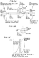
- a loss represented along Y axis relative to a wavelength represented along X axis indicates that lights of wavelengths W1 to W2 having the X axis polarization are passed through the coiled portion 402, while lights of less than the wavelength W1 having the Y axis polarization and of more than the wavelength W2 having the X axis polarization are prohibited from the transmission.
- a WDM signal light 200 of the wavelength range W1 to W2 having the X axis polarization is supplied to the input portion 400 of the polarizer 5c along with the ASE light 201, so that the WDM signal light and the X axis polarization component of the ASE light 201 are transmitted through the coiled portion 402, while the Y axis component of the ASE light 201 is prohibited from the transmission through the coiled portion 402 to be partially radiated from the outer surface thereof. Consequently, the WDM signal light 200 is obtained at the output portion 401.
- the ASE light removal unit 100 comprises the aforementioned PBS 5a which can be rotated along the light propagation axis, a branch coupler 6 having two output ports for branching the WDM signal light 200 by two, an optical detector 8 for converting a branched one of the WDM signal light 200 into an electric signal, a control circuit 9 for generating a control signal for the rotation of the PBS 5a, and a driving circuit 10 for rotating the PBS 5a in accordance with the control signal.
- the amplified WDM signal light 200 having a polarization is supplied to the PBS 5a which is controlled to be coincident with the polarization of the WDM signal light 200.
- the WDM signal light 200 is transmitted therethrough, and the ASE light 201 is reflected in the orthogonal direction to the light propagation direction for the polarization component orthogonal to the polarization of the WDM signal light 200 as explained in the first preferred embodiment shown in Fig. 2.
- the WDM signal light 200 is supplied to the branch coupler 6 to be branched by two. One of the branched lights is supplied to the optical detector 8 and the other one is supplied to a next stage as the output signal light.
- the WDM signal light 200 is converted into an electric signal to be supplied to the control circuit 9.
- a voltage of the electric signal is judged whether it is a predetermined maximum voltage or not. If the voltage is maximum, a transmission rate of the PBS 5a is maximum, namely, the PBS 5a is well controlled in polarization plane to pass the WDM signal light 200.
- the control signal is supplied from the control circuit 9 to the driving circuit 10.
- the PBS 5a is rotated with the driving circuit 10 until the voltage becomes maximum. Namely, the PBS 5a is adopted in polarization plane to the WDM signal light 200.
- the ASE light 201 having arbitrary polarizations is removed by using the PBS 5a, so that the ASE light 201 in a WDM signal light band can be reduced approximately by a half. Consequently, the optical amplification system having low noise characteristics is obtained.
- the PBS 5a is rotated, so that the WDM signal light 200 may have any linear polarization.
- the polarization of the WDM signal light 200 is elliptical or circular, however, a loss for the WDM signal light 200 occurs in the PBS 5a. Especially, if it is circular, the loss becomes maximum in such an extent that the ASE light 201 is removed. Even if such a case, however, a signal to noise ratio is not lowered as compared to that in the case where there is no provision of the ASE light removal unit 101.
- a polarization of a signal light is changed under the transmission via am optical fiber which is subject to external disturbance, etc.
- the optical amplification system in the second preferred embodiment is effective even for a signal light which has been transmitted via an optical fiber.
- the PBS 5a may be replaced by the lami-pole device 5b or optical polarizer 5c in the same manner as in the first preferred embodiment.
- the ASE light removal unit 101 comprises the aforementioned PBS 5a, branch coupler 6, and optical detector 8, and a polarization controller 7 for controlling the polarization of the amplified WDM signal light 200 to be pass through the PBS 5a, a control circuit 9 for controlling the polarization controller 7, and a driving circuit 10 for driving the polarization controller 7 to be rotated.
- the polarization controller 7 is of fiber squeezers, which individual fiber squeezers squeeze the fiber alternately at 0° and 45° to the vertical, causing a relative phase shift between two orthogonal eigenmodes, as described in pages 1217 to 1224 of "IEEE JOURNAL OF LIGHTWAVE TECHNOLOGY, VOL. 9, NO. 10, OCTOBER 1991".
- the amplified WDM signal light 200 having an arbitrary polarization is supplied to the polarization controller 7.
- the polarization of the WDM signal light 200 is tuned to a predetermined polarization of, for instance, X-axis polarization which can pass through the PBS 5a.
- the WDM signal light 200 is supplied to the PBS 5a.
- the WDM signal light 200 is transmitted therethrough, and the ASE light 201 is reflected in the orthogonal direction to the light propagation direction for the Y axis component as explained in the first preferred embodiment shown in Fig. 2.
- the WDM signal light 200 is supplied to the branch coupler 6 and branched by two in the branch coupler 6.
- the branched one is supplied to the optical detector 8 and the other one is supplied to a next stage as the output signal light.
- the WDM signal light 200 is supplied to the optical detector 8
- the WDM signal light 200 is converted into an electric signal to be supplied to the control circuit 9.
- a voltage of the electric signal is judged whether it is a predetermined maximum voltage or not. If the voltage is maximum, a transmission rate of the PBS 5a is maximum, namely, the polarization controller 7 is well controlled in polarization plane to pass the WDM signal light 200.
- the control signal is supplied from the control circuit 9 to the driving circuit 10.
- the polarization controller 7 that is, the fiber squeezers
- the polarization controller 7 is rotated to make the voltage maximum, so that the polarization plane of the WDM signal light 200 is coincident with that of the PBS 5a.
- the ASE light 201 having arbitrary polarizations is removed by using the PBS 5a, so that the ASE light 201 in a WDM signal light band can be reduced approximately by a half. Consequently, the optical amplification system having low noise characteristics is obtained.
- the polarization controller 7 is included therein, so that the WDM signal light 200 may have any linear polarization. Namely, any arbitrary polarization of the WDM signal light 200 can be changed to the predetermined linear polarization, so that the optical amplification system can be adopted to the WDM signal light 200 having the arbitrary polarization state.
- the polarization of the input signal light is changed to the predetermined polarization which can be passed through the PBS 5a by the polarization controller 7, so that a polarization dispersion of the optical fiber is compensated, and parts used therein are reduced in number.
- the PBS 5a may be replaced by the lami-pole device 5b or optical polarizer 5c in the same manner as in the first preferred embodiment.
- the polarization controller 7 may be positioned, for example, in front of the WDM coupler 2 or at the inside of the optical amplification unit 100.
- the polarization controller 7 may be of a type using a wavelength plate etc. instead of the fiber squeezers.
- a rare-earth element doped optical fiber may be replaced by a semiconductor optical amplifier or a Raman amplifier.
- Erbium may be replaced by the other rare-earth element.
- a predetermined wavelength of signal light has to be selected in using the other rare-earth element.
- the wavelength of signal light is 1.3 ⁇ m.
- a wavelength of the pump light for exciting the Er-doped fiber 4 may be of 1.48 ⁇ m etc. instead of 0.98 ⁇ m.
- a excitation method may be of a forward excitation, a backward excitation or both excitations.
- a band pass optical filter may be used to be connected to an output of the Er-doped optical fiber 4, and the band thereof must be larger than a band of the signal light, for example, 0.5 nm, 1.0 nm or 3 nm.
- an optical isolator of polarization independent type can be used either in front of the Er-doped optical fiber 4 or at the back of the Er-doped optical fiber 4.
- the optical isolator used in the first preferred embodiment is not always the polarization independent type, especially, in case where it is connected to output of the Er-doped optical fiber 4, the PSB 5a may be replaced by the optical isolator of polarization independent type.
- the optical isolator of polarization dependent may be used thereat.
- the PBS may be replaced by the optical isolator of polarization dependent type.
- the optical isolator of polarization dependent type may be used to be connected to an output of the polarization controller 7 shown in Fig. 7.
Abstract
Description
- This invention relates to an optical amplification system, and more particularly, to an optical amplification system having low noise characteristics.
- A first conventional optical amplification system comprises a pump light source for emitting a pump light having a wavelength of, for instance, 0.98 µm, an optical coupler for coupling a signal light having a wavelength of, for instance, 1,55 µm and the pump light to provide a coupled light, and an Er(erbium)-doped optical fiber for amplifying the signal light, as described on pages 551 to 553 of "IEEE PHOTONICS TECHNOLOGY LETTER, VOL. 3, No. 6, June, 1991".
- In the Er-doped optical fiber, the signal light included in the coupled light is amplified in accordance with the pumping with the pump light. Thus, the amplified signal light is obtained therein to be supplied to a following stage.
- However, an amplified spontaneous emission (ASE) light having arbitrary polarizations is also generated in the Er-doped optical fiber, so that the ASE light will be noise at the following stage. Further, a ASE light beat noise generated among wavelengths of the ASE light NASE-ASE is added to the output light of the Er-doped optical fiber. The ASE light beat noise NASE-ASE is defined by the equation.

where mt is a transverse mode degree, G is am amplification gain of the Er-doped optical fiber, nsp is an population distribution parameter of an amplification medium, and Δν is the ASE light bandwidth. Therefore, the ASE light is suppressed by controlling the population distribution parameter of Er atoms to be, for instance, 1. Consequently, low noise amplification is realized in the first conventional optical amplification system. - A second conventional optical amplification system comprises a pump light source, an optical coupler, an Er-doped optical fiber, and an optical filter which is connected to an output of the Er-doped optical fiber as described in pages 288 to 297 of "INSTITUTE OF ELECTRONICS, INFORMATION AND COMMUNICATION ENGINEERS OF JAPAN PAPERS B-I, VOL. J75-B-I, No. 5 ".
- In the optical filter, ASE lights generated in the Er-doped fiber having wavelengths equal and proximate a wavelength of a signal light pass, while ASE lights having other wavelengths are removed therein. Consequently, a low noise amplification system is realized in the second conventional optical amplification system. The similar systems are described in Japanese Kokai No. 1-298785, No. 1-127886 and No. 1-152819.
- In the first conventional optical amplification system, however, there is a disadvantage in that ASE lights inside the signal light band can not be reduced, because a band-pass optical filter is used.
- Further, the second conventional optical amplification system has a disadvantage in that the transverse mode degree mt of the ASE light is equivalently to be 2 to result in the generation of beat noise which is surplus by times of the transverse mode degree mt, because polarizations of the ASE light generated in the Er-doped optical fiber are random.
- Accordingly, it is an object of the invention to provide an optical amplification system having a low noise characteristic, in which an amplified spontaneous emission (ASE) light having an arbitrary polarization is can be removed.
- It is a further object of the invention to provide an optical amplification system having low noise characteristics, in which ASE lights inside a signal light band are removed.
- It is a further object of the invention to provide an optical amplification system, in which a signal light having an arbitrary polarization is passed through an ASE removal unit.
- It is a still further object of the invention to provide an optical amplification system, in which a polarization of a signal light is controlled in an ASE removal unit.
- According to the invention, an optical amplification system, comprises:
an optical amplification unit comprising a pump light source for emitting a pump light, a wavelength division multiplexing coupler for coupling a supplied signal light and the pump light to provide a coupled light, a erbium-doped optical fiber for amplifying the signal light by absorbing the pump light to provide an amplified signal light and the signal light being of a predetermined polarization; and
an amplified spontaneous emission light removal unit comprising means for removing an amplified spontaneous emission light being of other polarizations than the predetermined polarization. - The invention will be described in detail in connection with the drawings in which:
- Fig. 1 is a block diagram showing an optical amplification system of a first preferred embodiment according to the invention;
- Fig. 2 is a block diagram showing a removing device included in the optical amplification system of the first preferred embodiment according to the invention;
- Figs. 3A to 3C are explanatory diagrams showing operation of the optical amplification system of the first preferred embodiment according to the invention;
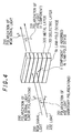
- Fig. 4 is a schematic perspective view showing a further removing device included in the optical amplification system of the first preferred embodiment according to the invention;
- Fig. 5A and 5B are schematic perspective and cross sectional view showing a still further removing device used in the first preferred embodiment;
- Fig. 5C is a graph explaining a loss relative to a wavelength for the removing device in Fig. 5A and Fig. 5B;
- Fig. 6 is a block diagram showing an optical amplification system of a second preferred embodiment according to the invention; and
- Fig. 7 is a block diagram showing an optical amplification system of a third preferred embodiment according to the invention.
- An optical amplification system in the first preferred embodiment according to the invention will be explained in Fig. 1.
- The optical amplification system comprises an
optical amplification unit 100 for amplifying a WDM (Wavelength Division Multiplexing) signal light of a predetermined polarization having four wavelengths of


light removal unit 101 for removing a noise component in the amplified WDM signal light to provide an output signal light. - The
optical amplification unit 100 comprises apump light source 3 for emitting a pump light having a wavelength of 0.98 µm, a WDM (Wavelength Division Multiplexing)coupler 2 for coupling the WDM signal light and the pump light to provide a coupled light, and an Er(erbium)-dopedoptical fiber 4 for amplifying the WDM signal light in the coupled light by absorbing the pump light to provide the amplified WDM signal light. - The ASE
light removal unit 101 comprises a PBS (polarization beam splitter) 5a shown in Fig. 2 for removing the ASE light having a polarization component among arbitrary polarizations. - In the
optical amplification unit 100, for example, thepump light souse 2 has a 0.98 µm wavelength LD which has an active layer consisting of an InGaAs/AlGaAs strained double-quantum well (SDOW) layer, and the Er-dopedoptical fiber 4 has an Er concentration of 80 ppm, a mode-field diameter of 6 µm, and a length of 60 m. - In operation, the
WDM signal light 200 having four wavelengths λ₁ to λ₄ of a common linear polarization as shown in Fig. 3A is supplied from a DFB-LD (not shown). to theWDM coupler 2 to be coupled with the pump light supplied from thepump light source 3. A light thus coupled is supplied to the Er-dopedoptical fiber 4. - At the Er-doped
fiber 4, the pump light is absorbed therein so that theWDM signal light 200 is amplified thereby. After that, the amplifiedWDM signal light 200 is supplied to the ASElight removal unit 101. - The
WDM signal light 200 is amplified as described above, while theASE light 201 having arbitrary polarizations is generated in the Er-dopedoptical fiber 4. Fig. 3B shows a spectrum of an output light of theoptical amplification unit 100. As shown in Fig. 3B, theASE light 201 is indicated to be semicircular along with the amplifiedWDM signal light 200. Thus, the ASElight 201 will be a noise of the output light supplied from the optical amplification system. - Next, the amplified
WDM light 200 is supplied to the PBS 5a. As shown in Fig. 2, in the PBS 5a, theWDM signal light 200 having the linear polarization of X axis is transmitted therethrough without being absorbed therein, while theASE light 201 having the arbitrary polarizations is transmitted therethrough for the X axis component, and is reflected in the orthogonal direction to the light propagation direction for the Y axis component. - Fig. 3C shows a spectrum of the output light of the ASE light removal unit 101 (PBS 5a). In Fig. 3 C, a dotted line is for the ASE
light 201 before being passed through the PBS 5a and a solid line is for the ASElight 201 after being passed through the PBS 5a. - As shown in Fig. 3C, the optical amplification system of the first preferred embodiment has the PBS 5a, so that the ASE light 201 in a WDM signal light band can be reduced approximately by a half. Consequently, the optical amplification system having a low noise characteristic is obtained.
- Generally, a transmission signal light of an optical transmitter in an optical communication system is obtained by modulating an injection current of a semiconductor laser, or an output light of the semiconductor laser using a intensity optical modulator such as a LiNbO₃ optical modulator. An output signal light of this optical transmitter is maintained with a constant linear polarization state, so that the optical amplification system of the first preferred embodiment is connected to an output of the optical transmitter. When the optical amplification system of the first preferred embodiment is actually used as a booster amplifier for transmitting an output signal of a high power, a good characteristic is obtained.
- In the first preferred embodiment, the ASE
light removal unit 101 adopts the PBS 5a as a first example. The PBS 5a may be replaced as a second example by a lami-pole device (Trademark) 5b as explained in the Japanese Patent No. 1351184, and as also shown in Fig. 4. - In Fig. 4, the lami-pole device is composed of metal layers 300 and
dielectric layer 301 alternately stacked, so that theWDM signal light 200 of the X-axis polarization is passed therethrough, while theASE light 201 of the arbitrary polarizations is absorbed therein, thereby resulting in the transmission of theWDM signal light 200. - Further, the PBS 5a may be replaced as a third example by an
optical polarizer 5c. Theoptical polarizer 5c is shown in Fig. 5A to 5C. Theoptical polarizer 5c comprises aninput portion 400, acoiled portion 402, and anoutput portion 401 as shown in Fig. 5A, such that it comprises a pair ofcores 403 arranged in the direction of a polarization to be transmitted therethrough and acladding layer 404 for covering thecores 403 in a transverse cross section thereof, as shown in Fig. 5B. Theoptical polarizer 5c has a property as shown in Fig. 5C, wherein a loss represented along Y axis relative to a wavelength represented along X axis indicates that lights of wavelengths W₁ to W₂ having the X axis polarization are passed through the coiledportion 402, while lights of less than the wavelength W₁ having the Y axis polarization and of more than the wavelength W₂ having the X axis polarization are prohibited from the transmission. - In operation, a
WDM signal light 200 of the wavelength range W₁ to W₂ having the X axis polarization is supplied to theinput portion 400 of thepolarizer 5c along with the ASE light 201, so that the WDM signal light and the X axis polarization component of the ASE light 201 are transmitted through the coiledportion 402, while the Y axis component of the ASE light 201 is prohibited from the transmission through the coiledportion 402 to be partially radiated from the outer surface thereof. Consequently, theWDM signal light 200 is obtained at theoutput portion 401. - Next the optical amplification system in the second preferred embodiment according to the invention will be explained in Fig. 6, wherein like parts are indicated by like reference numerals.
- The ASE
light removal unit 100 comprises the aforementioned PBS 5a which can be rotated along the light propagation axis, abranch coupler 6 having two output ports for branching theWDM signal light 200 by two, anoptical detector 8 for converting a branched one of theWDM signal light 200 into an electric signal, acontrol circuit 9 for generating a control signal for the rotation of the PBS 5a, and a drivingcircuit 10 for rotating the PBS 5a in accordance with the control signal. - In operation, the amplified
WDM signal light 200 having a polarization is supplied to the PBS 5a which is controlled to be coincident with the polarization of theWDM signal light 200. At the PBS 5a, theWDM signal light 200 is transmitted therethrough, and the ASE light 201 is reflected in the orthogonal direction to the light propagation direction for the polarization component orthogonal to the polarization of theWDM signal light 200 as explained in the first preferred embodiment shown in Fig. 2. - The
WDM signal light 200 is supplied to thebranch coupler 6 to be branched by two. One of the branched lights is supplied to theoptical detector 8 and the other one is supplied to a next stage as the output signal light. - At the
optical detector 8, theWDM signal light 200 is converted into an electric signal to be supplied to thecontrol circuit 9. - At the
control circuit 9, a voltage of the electric signal is judged whether it is a predetermined maximum voltage or not. If the voltage is maximum, a transmission rate of the PBS 5a is maximum, namely, the PBS 5a is well controlled in polarization plane to pass theWDM signal light 200. - When the voltage is not the maximum value, the control signal is supplied from the
control circuit 9 to the drivingcircuit 10. In accordance with the control signal, the PBS 5a is rotated with the drivingcircuit 10 until the voltage becomes maximum. Namely, the PBS 5a is adopted in polarization plane to theWDM signal light 200. - As described above, in the optical amplification system of the second preferred embodiment, the ASE light 201 having arbitrary polarizations is removed by using the PBS 5a, so that the ASE light 201 in a WDM signal light band can be reduced approximately by a half. Consequently, the optical amplification system having low noise characteristics is obtained.
- In the second preferred embodiment, the PBS 5a is rotated, so that the
WDM signal light 200 may have any linear polarization. If the polarization of theWDM signal light 200 is elliptical or circular, however, a loss for theWDM signal light 200 occurs in the PBS 5a. Especially, if it is circular, the loss becomes maximum in such an extent that the ASE light 201 is removed. Even if such a case, however, a signal to noise ratio is not lowered as compared to that in the case where there is no provision of the ASElight removal unit 101. Actually, a polarization of a signal light is changed under the transmission via am optical fiber which is subject to external disturbance, etc. In fact, however, there is a low provability that a linear polarization is changed to a circular polarization for a signal light transmitting via an optical fiber. For this reason, the optical amplification system in the second preferred embodiment is effective even for a signal light which has been transmitted via an optical fiber. - In the second preferred embodiment, the PBS 5a may be replaced by the lami-
pole device 5b oroptical polarizer 5c in the same manner as in the first preferred embodiment. - The optical amplification system in the third preferred embodiment according to the invention will be explained in Fig. 7, wherein like parts are indicated by like reference numerals.
- The ASE
light removal unit 101 comprises the aforementioned PBS 5a,branch coupler 6, andoptical detector 8, and apolarization controller 7 for controlling the polarization of the amplifiedWDM signal light 200 to be pass through the PBS 5a, acontrol circuit 9 for controlling thepolarization controller 7, and a drivingcircuit 10 for driving thepolarization controller 7 to be rotated. - The
polarization controller 7 is of fiber squeezers, which individual fiber squeezers squeeze the fiber alternately at 0° and 45° to the vertical, causing a relative phase shift between two orthogonal eigenmodes, as described in pages 1217 to 1224 of "IEEE JOURNAL OF LIGHTWAVE TECHNOLOGY, VOL. 9, NO. 10, OCTOBER 1991". - In operation, the amplified
WDM signal light 200 having an arbitrary polarization is supplied to thepolarization controller 7. At thepolarization controller 7, the polarization of theWDM signal light 200 is tuned to a predetermined polarization of, for instance, X-axis polarization which can pass through the PBS 5a. - The
WDM signal light 200 is supplied to the PBS 5a. At the PBS 5, theWDM signal light 200 is transmitted therethrough, and the ASE light 201 is reflected in the orthogonal direction to the light propagation direction for the Y axis component as explained in the first preferred embodiment shown in Fig. 2. - The
WDM signal light 200 is supplied to thebranch coupler 6 and branched by two in thebranch coupler 6. The branched one is supplied to theoptical detector 8 and the other one is supplied to a next stage as the output signal light. - When the
WDM signal light 200 is supplied to theoptical detector 8, theWDM signal light 200 is converted into an electric signal to be supplied to thecontrol circuit 9. - At the
control circuit 9, a voltage of the electric signal is judged whether it is a predetermined maximum voltage or not. If the voltage is maximum, a transmission rate of the PBS 5a is maximum, namely, thepolarization controller 7 is well controlled in polarization plane to pass theWDM signal light 200. - When the voltage is not the maximum value, the control signal is supplied from the
control circuit 9 to the drivingcircuit 10. In accordance with the control signal, the polarization controller 7 (that is, the fiber squeezers) is rotated to make the voltage maximum, so that the polarization plane of theWDM signal light 200 is coincident with that of the PBS 5a. - As described above, in the optical amplification system of the third preferred embodiment, the ASE light 201 having arbitrary polarizations is removed by using the PBS 5a, so that the ASE light 201 in a WDM signal light band can be reduced approximately by a half. Consequently, the optical amplification system having low noise characteristics is obtained.
- In the third preferred embodiment, the
polarization controller 7 is included therein, so that theWDM signal light 200 may have any linear polarization. Namely, any arbitrary polarization of theWDM signal light 200 can be changed to the predetermined linear polarization, so that the optical amplification system can be adopted to theWDM signal light 200 having the arbitrary polarization state. - Further, in the third preferred embodiment, the polarization of the input signal light is changed to the predetermined polarization which can be passed through the PBS 5a by the
polarization controller 7, so that a polarization dispersion of the optical fiber is compensated, and parts used therein are reduced in number. - In the third preferred embodiment, the PBS 5a may be replaced by the lami-
pole device 5b oroptical polarizer 5c in the same manner as in the first preferred embodiment. If thepolarization controller 7 is positioned before the PBS 5a, thepolarization controller 7 may be positioned, for example, in front of theWDM coupler 2 or at the inside of theoptical amplification unit 100. Thepolarization controller 7 may be of a type using a wavelength plate etc. instead of the fiber squeezers. - In the first to third preferred embodiment, a rare-earth element doped optical fiber may be replaced by a semiconductor optical amplifier or a Raman amplifier. As a material doped in an optical fiber for amplifying the
WDM signal light 200, Erbium may be replaced by the other rare-earth element. In that case, however, a predetermined wavelength of signal light has to be selected in using the other rare-earth element. For example, in case of a Pr(praseodymium)-doped optical amplification unit, the wavelength of signal light is 1.3 µm. A wavelength of the pump light for exciting the Er-dopedfiber 4 may be of 1.48 µm etc. instead of 0.98 µm. A excitation method may be of a forward excitation, a backward excitation or both excitations. - For removing the ASE light 201 outside the band of the
WDM signal light 200, a band pass optical filter may be used to be connected to an output of the Er-dopedoptical fiber 4, and the band thereof must be larger than a band of the signal light, for example, 0.5 nm, 1.0 nm or 3 nm. - For stabilizing the operation of the
optical amplification unit 100, an optical isolator of polarization independent type can be used either in front of the Er-dopedoptical fiber 4 or at the back of the Er-dopedoptical fiber 4. The optical isolator used in the first preferred embodiment is not always the polarization independent type, especially, in case where it is connected to output of the Er-dopedoptical fiber 4, the PSB 5a may be replaced by the optical isolator of polarization independent type. In the second and third preferred embodiments, in case where the optical isolator is used at the back of the PBS, the optical isolator of polarization dependent may be used thereat. In the third preferred embodiment, the PBS may be replaced by the optical isolator of polarization dependent type. Furthermore, if an another polarization controller is used in front of thepolarization controller 7 shown in Fig. 7, the optical isolator of polarization dependent type may be used to be connected to an output of thepolarization controller 7 shown in Fig. 7. - Although the invention has been described with respect to specific embodiment for complete and clear disclosure, the appended claims are not to be thus limited but are to be construed as embodying all modification an alternative constructions that may be occur to one skilled in the art which fairly fall within the basic teaching here is set forth.
Claims (9)
- An optical amplification system, comprising:
an optical amplifier for amplifying an input signal light to provide an amplified signal light, said input signal light and said amplified signal light being of a predetermined polarization; and
means for only transmission of an input light being of said predetermined polarization, so that said amplified signal light is transmitted therethrough, while input lights of other polarizations than said predetermined polarization is prohibited from being transmitted therethrough. - An optical amplification system, comprising:
an optical amplification unit comprising a pump light source for emitting a pump light, a wavelength division multiplexing coupler for coupling a supplied signal light and said pump light to provide a coupled light, a erbium-doped optical fiber for amplifying said signal light by absorbing said pump light to provide an amplified signal light and said signal light being of a predetermined polarization; and
an amplified spontaneous emission light removal unit comprising means for removing an amplified spontaneous emission light being of other polarizations than said predetermined polarization. - An optical amplification system, according to claim 2, wherein:
said removing means comprises a polarization separation element having a polarization state for passing said predetermined polarization, through which said signal light is passed and said amplified spontaneous emission light is removed thereat. - An optical amplification system, according to claim 3, wherein:
said removing means further comprises an branch coupler having two output ports for branching said signal light in which said amplified signal light is divided into first and second signal light;
an optical detector for converting said first signal light into an electric signal;
a control circuit for generating a control signal to control a polarization of said polarization separation element to be tuned to said predetermined polarization of said signal light in accordance with said electric signal;
a driving circuit for driving said polarization separation element in accordance with control of said control circuit, so that said polarization thereof is tuned to said predetermined polarization of said signal light. - An optical amplification system, according to claim 3, wherein:
said removing means further comprises a polarization controller for controlling a polarization of said signal light to be said predetermined polarization;
an branch coupler having two output ports for branching the said signal light in which said amplified signal light is divided into first and second signal light;
an optical detector for converting said first signal light into an electric signal;
a control circuit for generating a control signal to control said polarization controller to be tuned to said predetermined polarization of said signal light in accordance with said electric signal;
a driving circuit for driving said polarization controller in accordance with control of said control circuit, so that said polarization thereof is tuned to said predetermined polarization of said signal light. - An optical amplification system, according to any of claims 3 to 5, wherein:
said polarization separation element is a polarization beam splitter, through which said signal light is passed and said amplified spontaneous emission light is reflected thereat. - An optical amplification system, according to any of claims 3 to 5, wherein:
said polarization separation element is a lami-pole device having metal layers and dielectric layers, through which said signal light is passed and said amplified spontaneous emission light is absorbed thereat. - An optical amplification system, according to any of claims 3 to 5, wherein:
said polarization separation element is an optical polarizer which comprises an input portion, a coiled portion, an output portion in axis direction, and a pair of cores arranged in a direction of a polarization to be transmitted therethrough and a cladding layer for covering said cores in a transverse cross-section, through which said signal light is passed and said amplified spontaneous emission light is radiated from the outer surface thereof not to be transmitted. - An optical amplification system, according to any of claims 5 to 8, wherein:
said polarization controller is of fiber squeezers for controlling said polarization of said signal light to be passed through said polarization separation element.
Applications Claiming Priority (2)
| Application Number | Priority Date | Filing Date | Title |
|---|---|---|---|
| JP4318708A JP2536288B2 (en) | 1992-11-27 | 1992-11-27 | Optical amplifier |
| JP318708/92 | 1992-11-27 |
Publications (2)
| Publication Number | Publication Date |
|---|---|
| EP0599352A1 true EP0599352A1 (en) | 1994-06-01 |
| EP0599352B1 EP0599352B1 (en) | 1997-02-05 |
Family
ID=18102104
Family Applications (1)
| Application Number | Title | Priority Date | Filing Date |
|---|---|---|---|
| EP93119203A Expired - Lifetime EP0599352B1 (en) | 1992-11-27 | 1993-11-29 | Optical amplification system |
Country Status (6)
| Country | Link |
|---|---|
| US (1) | US5526174A (en) |
| EP (1) | EP0599352B1 (en) |
| JP (1) | JP2536288B2 (en) |
| AU (1) | AU674545B2 (en) |
| CA (1) | CA2110191C (en) |
| DE (1) | DE69307994T2 (en) |
Cited By (2)
| Publication number | Priority date | Publication date | Assignee | Title |
|---|---|---|---|---|
| DE10230091A1 (en) * | 2002-07-04 | 2004-01-29 | Siemens Ag | Method for measuring the signal-to-noise ratios of a wavelength division multiplex (-WDM) signal |
| CN108808431A (en) * | 2018-07-11 | 2018-11-13 | 电子科技大学 | A kind of mixing Random Laser distributed air-defense method based on weak Er-doped fiber |
Families Citing this family (9)
| Publication number | Priority date | Publication date | Assignee | Title |
|---|---|---|---|---|
| US5636053A (en) * | 1995-06-15 | 1997-06-03 | E-Tek Dynamics, Inc. | Fiberoptic amplifier system with noise figure reduction |
| JP2962248B2 (en) * | 1996-11-01 | 1999-10-12 | 日本電気株式会社 | Optical amplifier for wavelength multiplexed optical transmission |
| JP2003069114A (en) * | 2001-08-27 | 2003-03-07 | Fujikura Ltd | Photoamplifier |
| JP2003031875A (en) * | 2001-07-13 | 2003-01-31 | Fujikura Ltd | Polarization-preserving optical fiber amplifier |
| KR100460204B1 (en) * | 2002-06-25 | 2004-12-13 | 경북대학교 산학협력단 | Improving Method of Noise Figure using Polarization Beam Splitter for Erbium Doped Fiber Amplifier |
| KR100475510B1 (en) * | 2002-07-27 | 2005-03-10 | 경북대학교 산학협력단 | Gain and Noise figure improving Method for Erbium-doped fiber amplifier with double-pass using a polarization beam splitter and mirror |
| JP4359035B2 (en) * | 2002-11-21 | 2009-11-04 | 富士通株式会社 | Optical repeater |
| JP2008092123A (en) * | 2006-09-29 | 2008-04-17 | Fujitsu Ltd | Compensation method and compensator of primary polarization mode dispersion, and optical transmission system using the same |
| JP6736504B2 (en) * | 2017-03-07 | 2020-08-05 | Kddi株式会社 | Optical amplifier |
Citations (1)
| Publication number | Priority date | Publication date | Assignee | Title |
|---|---|---|---|---|
| JPH01224732A (en) * | 1988-03-04 | 1989-09-07 | Kokusai Denshin Denwa Co Ltd <Kdd> | Optical amplifying system for long-distance optical communication system |
Family Cites Families (11)
| Publication number | Priority date | Publication date | Assignee | Title |
|---|---|---|---|---|
| JPS6426826A (en) * | 1987-07-23 | 1989-01-30 | Kokusai Denshin Denwa Co Ltd | Optical amplification system |
| US4941738A (en) * | 1988-07-29 | 1990-07-17 | American Telephone And Telegraph Company | Polarization independent optical amplifier apparatus |
| US5210808A (en) * | 1989-07-17 | 1993-05-11 | Pirelli Cavi S.P.A. | Unit for amplifying light signals in optical fiber transmission lines |
| JPH03127886A (en) * | 1989-10-13 | 1991-05-30 | Mitsubishi Cable Ind Ltd | Light amplifier |
| JP2649737B2 (en) * | 1990-07-05 | 1997-09-03 | 国際電信電話株式会社 | Pumping light source drive method for optical amplifier |
| JPH04217233A (en) * | 1990-12-19 | 1992-08-07 | Nec Corp | Multiwavelength light amplifier |
| US5323260A (en) * | 1991-08-23 | 1994-06-21 | Alfano Robert R | Method and system for compressing and amplifying ultrashort laser pulses |
| JP2677726B2 (en) * | 1991-09-20 | 1997-11-17 | 富士通株式会社 | Optical transmitter |
| US5283686A (en) * | 1992-07-27 | 1994-02-01 | General Instrument Corporation, Jerrold Communications | Optical systems with grating reflector |
| US5223705A (en) * | 1992-08-12 | 1993-06-29 | At&T Bell Laboratories | Measurement of an optical amplifier parameter with polarization |
| US5303314A (en) * | 1993-03-15 | 1994-04-12 | The United States Of America As Represented By The Secretary Of The Navy | Method and apparatus for polarization-maintaining fiber optical amplification with orthogonal polarization output |
-
1992
- 1992-11-27 JP JP4318708A patent/JP2536288B2/en not_active Expired - Lifetime
-
1993
- 1993-11-29 EP EP93119203A patent/EP0599352B1/en not_active Expired - Lifetime
- 1993-11-29 DE DE69307994T patent/DE69307994T2/en not_active Expired - Lifetime
- 1993-11-29 US US08/158,566 patent/US5526174A/en not_active Expired - Lifetime
- 1993-11-29 AU AU52008/93A patent/AU674545B2/en not_active Expired
- 1993-11-29 CA CA002110191A patent/CA2110191C/en not_active Expired - Lifetime
Patent Citations (1)
| Publication number | Priority date | Publication date | Assignee | Title |
|---|---|---|---|---|
| JPH01224732A (en) * | 1988-03-04 | 1989-09-07 | Kokusai Denshin Denwa Co Ltd <Kdd> | Optical amplifying system for long-distance optical communication system |
Non-Patent Citations (3)
| Title |
|---|
| C.R.GILES ET AL.: "2-Gbit/s signal amplification at lambda=1.53 um in an Erbium-doped single-mode fiber amplifier", JOURNAL OF LIGHTWAVE TECHNOLOGY, vol. 7, no. 4, April 1989 (1989-04-01), NEW YORK US, pages 651 - 656, XP000032959 * |
| H.SHIMIZU ET AL.: "Highly practical fiber squeezer polarization controller", JOURNAL OF LIGHTWAVE TECHNOLOGY, vol. 9, no. 10, October 1991 (1991-10-01), NEW YORK US, pages 1217 - 1224, XP000241886 * |
| PATENT ABSTRACTS OF JAPAN vol. 13, no. 543 (P - 970) 6 December 1989 (1989-12-06) * |
Cited By (2)
| Publication number | Priority date | Publication date | Assignee | Title |
|---|---|---|---|---|
| DE10230091A1 (en) * | 2002-07-04 | 2004-01-29 | Siemens Ag | Method for measuring the signal-to-noise ratios of a wavelength division multiplex (-WDM) signal |
| CN108808431A (en) * | 2018-07-11 | 2018-11-13 | 电子科技大学 | A kind of mixing Random Laser distributed air-defense method based on weak Er-doped fiber |
Also Published As
| Publication number | Publication date |
|---|---|
| CA2110191A1 (en) | 1994-05-28 |
| EP0599352B1 (en) | 1997-02-05 |
| JPH06196786A (en) | 1994-07-15 |
| AU674545B2 (en) | 1997-01-02 |
| JP2536288B2 (en) | 1996-09-18 |
| US5526174A (en) | 1996-06-11 |
| DE69307994T2 (en) | 1997-05-22 |
| DE69307994D1 (en) | 1997-03-20 |
| AU5200893A (en) | 1994-06-09 |
| CA2110191C (en) | 1998-11-03 |
Similar Documents
| Publication | Publication Date | Title |
|---|---|---|
| US5623362A (en) | Erbium-doped fiber amplifier and an optical fiber communication system | |
| EP0812078B1 (en) | Optical communication system and optical amplifier | |
| US6529314B1 (en) | Method and apparatus using four wave mixing for optical wavelength conversion | |
| US5253104A (en) | Balanced optical amplifier | |
| EP1063795B1 (en) | Optical amplifier, optical transmission system comprising an optical amplifier, and method of amplifying an optical signal | |
| JP4900501B2 (en) | Optical amplifier and optical amplification method | |
| US5978130A (en) | Dual-band fiber optic amplification system using a single pump source | |
| US5274496A (en) | Optical amplifying repeater with monitor and control function | |
| US6414787B2 (en) | Optical fiber amplifier having a gain flattening filter | |
| US5598491A (en) | Optical fiber amplifier and optical fiber transmission apparatus | |
| EP0641051B1 (en) | Optical amplifier | |
| US6008933A (en) | Multiple stage optical fiber amplifier | |
| JPH10247895A (en) | Wavelength multiplex transmission device | |
| EP0883217B1 (en) | Optical fiber telecommunication system | |
| CA2135532C (en) | All-optical inverter | |
| EP0599352B1 (en) | Optical amplification system | |
| US5436751A (en) | Analog optical transmission system and optical fiber amplifier | |
| US6603896B1 (en) | Power fiber amplifier with flat gain | |
| EP0954071B1 (en) | Optical fiber amplifier | |
| EP1030415A2 (en) | Optical fiber amplifier and method of amplifying an optical signal | |
| JPH10326930A (en) | Gain-flattening optical fiber amplifier | |
| Seikai et al. | Experimental studies on wavelength division bidirectional optical amplifiers using an Er/sup 3+/-doped fiber | |
| EP1225665A2 (en) | Optical amplifier | |
| JP3250473B2 (en) | Optical amplifier | |
| JPH11330593A (en) | Broadband spontaneous emission type optical source |
Legal Events
| Date | Code | Title | Description |
|---|---|---|---|
| PUAI | Public reference made under article 153(3) epc to a published international application that has entered the european phase |
Free format text: ORIGINAL CODE: 0009012 |
|
| 17P | Request for examination filed |
Effective date: 19940317 |
|
| AK | Designated contracting states |
Kind code of ref document: A1 Designated state(s): DE FR GB IT NL |
|
| 17Q | First examination report despatched |
Effective date: 19950418 |
|
| GRAG | Despatch of communication of intention to grant |
Free format text: ORIGINAL CODE: EPIDOS AGRA |
|
| GRAH | Despatch of communication of intention to grant a patent |
Free format text: ORIGINAL CODE: EPIDOS IGRA |
|
| GRAH | Despatch of communication of intention to grant a patent |
Free format text: ORIGINAL CODE: EPIDOS IGRA |
|
| GRAA | (expected) grant |
Free format text: ORIGINAL CODE: 0009210 |
|
| AK | Designated contracting states |
Kind code of ref document: B1 Designated state(s): DE FR GB IT NL |
|
| REF | Corresponds to: |
Ref document number: 69307994 Country of ref document: DE Date of ref document: 19970320 |
|
| ITF | It: translation for a ep patent filed |
Owner name: 0508;04MIFMODIANO & ASSOCIATI S.R.L. |
|
| ET | Fr: translation filed | ||
| PLBE | No opposition filed within time limit |
Free format text: ORIGINAL CODE: 0009261 |
|
| STAA | Information on the status of an ep patent application or granted ep patent |
Free format text: STATUS: NO OPPOSITION FILED WITHIN TIME LIMIT |
|
| 26N | No opposition filed | ||
| REG | Reference to a national code |
Ref country code: GB Ref legal event code: IF02 |
|
| PGFP | Annual fee paid to national office [announced via postgrant information from national office to epo] |
Ref country code: DE Payment date: 20121121 Year of fee payment: 20 Ref country code: FR Payment date: 20121130 Year of fee payment: 20 |
|
| PGFP | Annual fee paid to national office [announced via postgrant information from national office to epo] |
Ref country code: GB Payment date: 20121128 Year of fee payment: 20 Ref country code: IT Payment date: 20121117 Year of fee payment: 20 |
|
| PGFP | Annual fee paid to national office [announced via postgrant information from national office to epo] |
Ref country code: NL Payment date: 20121116 Year of fee payment: 20 |
|
| REG | Reference to a national code |
Ref country code: DE Ref legal event code: R071 Ref document number: 69307994 Country of ref document: DE |
|
| REG | Reference to a national code |
Ref country code: NL Ref legal event code: V4 Effective date: 20131129 |
|
| REG | Reference to a national code |
Ref country code: GB Ref legal event code: PE20 Expiry date: 20131128 |
|
| PG25 | Lapsed in a contracting state [announced via postgrant information from national office to epo] |
Ref country code: GB Free format text: LAPSE BECAUSE OF EXPIRATION OF PROTECTION Effective date: 20131128 Ref country code: DE Free format text: LAPSE BECAUSE OF EXPIRATION OF PROTECTION Effective date: 20131130 |