EP0598967A1 - Cleaning gas turbine with abrasive blasting - Google Patents
Cleaning gas turbine with abrasive blasting Download PDFInfo
- Publication number
- EP0598967A1 EP0598967A1 EP92810914A EP92810914A EP0598967A1 EP 0598967 A1 EP0598967 A1 EP 0598967A1 EP 92810914 A EP92810914 A EP 92810914A EP 92810914 A EP92810914 A EP 92810914A EP 0598967 A1 EP0598967 A1 EP 0598967A1
- Authority
- EP
- European Patent Office
- Prior art keywords
- slide
- container
- gas turbine
- shut
- opening
- Prior art date
- Legal status (The legal status is an assumption and is not a legal conclusion. Google has not performed a legal analysis and makes no representation as to the accuracy of the status listed.)
- Withdrawn
Links
Images


Classifications
-
- F—MECHANICAL ENGINEERING; LIGHTING; HEATING; WEAPONS; BLASTING
- F01—MACHINES OR ENGINES IN GENERAL; ENGINE PLANTS IN GENERAL; STEAM ENGINES
- F01D—NON-POSITIVE DISPLACEMENT MACHINES OR ENGINES, e.g. STEAM TURBINES
- F01D25/00—Component parts, details, or accessories, not provided for in, or of interest apart from, other groups
- F01D25/002—Cleaning of turbomachines
-
- B—PERFORMING OPERATIONS; TRANSPORTING
- B24—GRINDING; POLISHING
- B24C—ABRASIVE OR RELATED BLASTING WITH PARTICULATE MATERIAL
- B24C7/00—Equipment for feeding abrasive material; Controlling the flowability, constitution, or other physical characteristics of abrasive blasts
Definitions
- the invention relates to a device for dry cleaning a gas turbine, which is connected to an exhaust pipe of a reciprocating piston internal combustion engine, with a granulate-like cleaning body-containing metering container, which is connected via a line to the exhaust pipe near the inlet of the gas turbine and to a supply line having a shut-off device is provided for compressed air, with the aid of compressed air, cleaning bodies are blown out of the metering container at the inlet of the gas turbine.
- the gas turbine can be used to drive a charge air compressor, a gearbox or an electrical generator. In all cases, deposits form on the turbine blades, which are removed by the cleaning bodies at intervals of one day to two days.
- the metering container has a filler neck in its lid, which can be closed with a threaded cap.
- the line leading from the dosing tank to the exhaust pipe also contains a shut-off device.
- the threaded cap For each cleaning process, the threaded cap must be unscrewed, whereupon a predetermined amount of granules, which depends on the size of the gas turbine is dependent, is filled into the dosing container by means of a funnel inserted into the filler neck, after which the threaded cap is screwed to the filler neck in a gastight manner.
- shut-off devices have to be opened one after the other so that the filled amount of cleaning bodies can be blown out of the metering container at the inlet of the gas turbine.
- both shut-off devices must be closed again and then a safety valve on the dosing tank must be opened in order to reduce the exhaust gas pressure prevailing in this tank. The safety valve is then closed again.
- the workload for such a cleaning process is complicated because of the cumbersome filling of the dosing container and because of the many actuations of the shut-off elements. Incorrect manipulation cannot be ruled out either. If there are several gas turbines on one reciprocating piston internal combustion engine or in systems with several reciprocating piston internal combustion engines and the associated gas turbines, the workload is multiplied considerably.
- the invention has for its object to improve a dry cleaning device of the type mentioned in such a way that it is easier to use and the possibility of incorrect manipulation can be reduced.
- this object is achieved in that, in addition to the metering container, a storage container for cleaning bodies is provided, which is connected to the metering container, and in that the metering container contains a slide which can be moved in at least two positions and which in one position accommodates cleaning bodies supplied from the storage container, the shut-off element closed in the supply line and the connection of the line to the inlet of the gas turbine are interrupted, and in another position in which the connection of the line to the inlet of the gas turbine and the shut-off device in the supply line are open, the cleaning bodies can be blown into the gas turbine.
- the presence of an additional storage container which holds a multiple of the amount of granules required for a cleaning process, drastically reduces the work involved in the cleaning process, since there is no need to laboriously open and close the filler neck or fill it with a funnel.
- the dosing container is simply filled by moving the slide to the appropriate filling position. After filling, the slide is brought into the blowing position, whereby the connection from the storage container to the dosing container is automatically interrupted. It is therefore no longer necessary to operate the line that previously ran from the metering container to the exhaust pipe. The possibility of incorrect manipulation is also reduced.
- the cleaning process can be simplified in that the slide is mechanically connected to the shut-off element in the supply line for compressed air. This means that the shut-off device for controlling the compressed air supply is actuated simultaneously with the movement of the slide.
- the cleaning device has an elevated storage container 1 for granular cleaning bodies, for example broken fruit seeds, and a metering container 2, which is arranged below the storage container 1.
- the capacity of the storage container is such that it has to be refilled after about 3 to 4 weeks.
- the lower end of the storage container 1 is connected to the upper end of the dosing container 2 via a transparent line 3.
- a connecting line 4 leads to an exhaust pipe 5, to the right end of which a gas turbine 6 is connected in FIG.
- the connecting line 4 contains a shut-off element 7, which for example has the shape of a ball valve and which is provided in order to be able to shut off the line 4 when the cleaning device or parts thereof have to be dismantled and / or inspected.
- the gas turbine 6 is part of a charging group, ie it drives a charge air compressor.
- the gas turbine 6 can also serve as a utility turbine, in that it serves to drive an electric generator. However, it can also be connected to the crankshaft of the internal combustion engine via a transmission in order to transmit exhaust gas energy to this shaft.
- the exhaust gas flowing through the gas turbine 6 comes from the cylinders a not shown piston engine of the diesel type, on the housing 10, the dry cleaning device is attached in a manner not shown.
- a compressed air line 8 is connected to the metering container 2 and has a shut-off element 9, for example in the form of a ball valve.
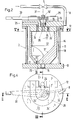
- the dosing container 2 has a cylindrical jacket 11, which is closed at the top by a container lid 12 and at the bottom by a container base 13.
- a slide 14 which can be pivoted about the axis 11 'of the container.
- the slide 14 has at its lower end a pin 15 which is mounted in a corresponding bore in the container bottom 13.
- the slide 14 also has a corresponding pin 16 at its upper end, which is mounted in a bore in the container lid 12.
- the slide 14 is composed of a lower part 18 surrounding a cavity 17 and an upper, plate-shaped part 19 which delimits the cavity 17 at the top.
- the cavity 17 is cylindrical in its upper section and then merges downwards into a funnel-like conical surface 17 '(FIG. 3).
- a further funnel-like conical surface 17'' is formed below the conical surface 17', which has smaller dimensions than the conical surface 17 'and whose conical axis 20 is eccentric to the container axis 11'.
- a bore 21 adjoins the smaller conical surface 17 ′′, which is closed by the container bottom 13 in the position of the slide 14 shown in FIG. In another position of the slide 14, the bore 21 is aligned with a bore 22 in the container bottom 13 (FIG. 3), the axis 23 of which is at the same distance from the container axis 11 'as the cone axis 20, which is also the axis of the bore 21.
- a through bore 24 aligned with the bore 21 (FIG. 2), which in the position shown in FIG. 2 is connected to an angular bore 25 in the container lid 12 and is used to vent the cavity 17.
- a further continuous ventilation channel 24 ' which is at the same distance from the container axis 11' as the bore 24 and which communicates with the angular bore 25 in a different position of the slide 14.
- a through bore 26 is provided in the container lid 12, to which the line 3 coming from the storage container 1 (FIG. 1) is connected in a manner not shown.
- a bore 27 in the plate-shaped part 19 of the slide 14 belongs to the bore 26.
- the bores 26 and 27, the axes of which are also equidistant from the container axis 11 ', are aligned with one another in a specific position of the slide 14, which is described in more detail below.
- the pin 16 of the slide 14 merges upwards into a hexagon 16 ', onto which a lever 30 is placed, which serves to pivot the slide 14.
- a position plate 29 extends above the lever 30 parallel to the container lid 12 and has a U-shape in plan (FIG. 4) and is attached to the container lid 12 at the end of the U-leg. Markings (not shown) for various operating positions of the lever 30 are attached to the position plate 29.
- the hexagon 16 continues upwards into an actuating spindle for the shut-off element 9 in the compressed air line 8, indicated by a broken line 31 in FIG.
- the line 8 ends radially at the edge of the container lid 12 and then continues as a radial channel 32 (FIG. 4) up to the bore receiving the pin 16.
- the pin has 16 has a radial channel 33 extending to its center, to which an axial bore 35 then adjoins at the bottom. Aligned to this hole, a hole 36 is present in the plate-shaped part 19, which opens into the cavity 17 (Fig.2).
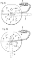
- the shut-off element 7 in the line 4 is open and the lever 30 is in the position shown in FIG. 6 a, which is identical to the position shown in FIG. 2.
- the bores 24 and 25 communicate in the slide 14 or in the container lid 12, so that the cavity 17 is in communication with the atmosphere.
- the shut-off element 9 in the compressed air line 8, which is also actuated by the lever 30, is in the closed position. Since the bores 21 and 22 on the one hand and 26 and 27 on the other hand are not in register, the cleaning device is not functioning. Channels 24 'and 33 are also blocked.
- the lever 30 has been pivoted 90 ° counterclockwise to FIG. 6a, so that the radial channel 33 in the pin 16 and the channel 32 in the container lid 12 are now aligned with one another.
- the bores 21 and 22 at the lower end of the slide 14 or in the container bottom 13 are also aligned.
- the shut-off element 9 in the compressed air line 8 has been brought into the open position by pivoting the lever 30, so that compressed air reaches the cavity 17 via the feed line 8.
- the cavity 17 and the line 4 are now purged with air, the purge air passing through the bores 21, 22 and the connecting line 4 into the exhaust pipe 5.
- the lever 30 is again moved 90 ° counterclockwise, so that it assumes the position shown in FIG. 6c.
- the compressed air supply via the line 8 is interrupted because of the closed position of the shut-off element 9.
- the bores 26 and 27 in the container lid 12 and in the slide 14 communicate, so that granular cleaning bodies from the storage container 1 via the transparent connecting line 3 (FIG. 1 ) get into the cavity 17.
- the ventilation duct 24 ′ now also communicates with the angled bore 25, so that the air contained in the cavity 17 can escape when it is filled. Because of the transparency of the line 3, it can be observed when the filling process has ended.
- the lever 30 is pivoted back by 90 °, ie clockwise, and assumes the position shown in FIG. 6d, which corresponds to the position in FIG. 6b.
- the shut-off element 9 in the compressed air line 8 is opened again and the channel 32 is aligned with the bore 33 and likewise the bores 21 and 22.
- the compressed air entering the cavity 17 now blows the cleaning bodies through the bores 21 and 22 and the line 4 with the open shut-off device 7 in the area of the inlet of the gas turbine 6.
- the cleaning bodies hit the blades of the gas turbine 6, as a result of which impurities sitting on the blades are detached.
- the device can also be operated automatically instead of manually, by the slide 14 being driven by a pneumatic cylinder or an electric servomotor.
- the device can also be modified such that the dosing container and the slide are designed such that the latter can be moved in a straight line into the different operating positions.
- the dry cleaning process can be carried out for all loads of the reciprocating piston internal combustion engine, but it preferably takes place when the machine is at full load.
Abstract
Description
Die Erfindung bezieht sich auf eine Einrichtung zum Trockenreinigen einer Gasturbine, die an ein Auspuffrohr einer Hubkolbenbrennkraftmaschine angeschlossen ist, mit einem granulatartige Reinigungskörper enthaltenden Dosierbehälter, der über eine Leitung mit dem Auspuffrohr nahe dem Eintritt der Gasturbine verbunden ist und der mit einer ein Absperrorgan aufweisenden Zufuhrleitung für Druckluft versehen ist, wobei mit Hilfe von Druckluft Reinigungskörper aus dem Dosierbehälter zum Eintritt der Gasturbine geblasen werden. Die Gasturbine kann zum Antrieb eines Ladeluftkompressors, eines Getriebes oder auch eines elektrischen Generators dienen. In allen Fällen entstehen Ablagerungen auf den Turbinenschaufeln, die in Abständen von einem Tag bis zwei Tagen durch die Reinigungskörper entfernt werden.The invention relates to a device for dry cleaning a gas turbine, which is connected to an exhaust pipe of a reciprocating piston internal combustion engine, with a granulate-like cleaning body-containing metering container, which is connected via a line to the exhaust pipe near the inlet of the gas turbine and to a supply line having a shut-off device is provided for compressed air, with the aid of compressed air, cleaning bodies are blown out of the metering container at the inlet of the gas turbine. The gas turbine can be used to drive a charge air compressor, a gearbox or an electrical generator. In all cases, deposits form on the turbine blades, which are removed by the cleaning bodies at intervals of one day to two days.
Bei einer bisher bekannten Reinigungseinrichtung der eingangs genannten Art (ABB-Vorschrift HZTL 90561) weist der Dosierbehälter in seinem Deckel einen Füllstutzen auf, der mit einer Gewindekappe verschliessbar ist. Ausserdem enthält auch die vom Dosierbehälter zum Auspuffrohr führende Leitung ein Absperrorgan. Für jeden Reinigungsvorgang muss die Gewindekappe abgeschraubt werden, woraufhin eine vorbestimmte Granulatmenge, die von der Grösse der Gasturbine abhängig ist, mittels eines in den Füllstutzen eingesetzten Trichters in den Dosierbehälter eingefüllt wird, wonach die Gewindekappe gasdicht mit dem Füllstutzen verschraubt wird. Dann müssen die beiden Absperrorgane nacheinander geöffnet werden, damit die eingefüllte Menge von Reinigungskörpern aus dem Dosierbehälter zum Eintritt der Gasturbine geblasen werden kann. Danach müssen beide Absperrorgane wieder geschlossen werden und dann ein Sicherheitsventil am Dosierbehälter geöffnet werden, um den in diesem Behälter herrschenden Abgasdruck abzubauen. Das Sicherheitsventil wird danach wieder geschlossen. Der Arbeitsaufwand für einen solchen Reinigungsvorgang ist wegen des umständlichen Füllens des Dosierbehälters und wegen der vielen Betätigungen der Absperrorgane kompliziert. Fehlmanipulationen können auch nicht ausgeschlossen werden. Bei Vorhandensein mehrerer Gasturbinen an einer Hubkolbenbrennkraftmaschine oder in Anlagen mit mehreren Hubkolbenbrennkraftmaschinen und den dazugehörigen Gasturbinen vervielfacht sich der Arbeitsaufwand beträchtlich.In a previously known cleaning device of the type mentioned at the outset (ABB specification HZTL 90561), the metering container has a filler neck in its lid, which can be closed with a threaded cap. In addition, the line leading from the dosing tank to the exhaust pipe also contains a shut-off device. For each cleaning process, the threaded cap must be unscrewed, whereupon a predetermined amount of granules, which depends on the size of the gas turbine is dependent, is filled into the dosing container by means of a funnel inserted into the filler neck, after which the threaded cap is screwed to the filler neck in a gastight manner. Then the two shut-off devices have to be opened one after the other so that the filled amount of cleaning bodies can be blown out of the metering container at the inlet of the gas turbine. Then both shut-off devices must be closed again and then a safety valve on the dosing tank must be opened in order to reduce the exhaust gas pressure prevailing in this tank. The safety valve is then closed again. The workload for such a cleaning process is complicated because of the cumbersome filling of the dosing container and because of the many actuations of the shut-off elements. Incorrect manipulation cannot be ruled out either. If there are several gas turbines on one reciprocating piston internal combustion engine or in systems with several reciprocating piston internal combustion engines and the associated gas turbines, the workload is multiplied considerably.
Der Erfindung liegt die Aufgabe zugrunde, eine Trockenreinigungseinrichtung der eingangs genannten Art dahingehend zu verbessern, dass sie einfacher bedient und die Möglichkeit von Fehlmanipulationen verringert werden kann.The invention has for its object to improve a dry cleaning device of the type mentioned in such a way that it is easier to use and the possibility of incorrect manipulation can be reduced.
Diese Aufgabe wird erfindungsgemäss dadurch gelöst, dass ausser dem Dosierbehälter ein mit diesem in Verbindung stehender Vorratsbehälter für Reinigungskörper vorgesehen ist und dass im Dosierbehälter ein in mindestens zwei Stellungen bewegbarer Schieber enthalten ist, der in einer Stellung aus dem Vorratsbehälter zugeführte Reinigungskörper aufnimmt, wobei das Absperrorgan in der Zufuhrleitung geschlossen und die Verbindung der Leitung zum Eintritt der Gasturbine unterbrochen sind, und der in einer anderen Stellung, in der die Verbindung der Leitung zum Eintritt der Gasturbine sowie das Absperrorgan in der Zufuhrleitung offen sind, das Blasen der Reinigungskörper zum Eintritt der Gasturbine gestattet.According to the invention, this object is achieved in that, in addition to the metering container, a storage container for cleaning bodies is provided, which is connected to the metering container, and in that the metering container contains a slide which can be moved in at least two positions and which in one position accommodates cleaning bodies supplied from the storage container, the shut-off element closed in the supply line and the connection of the line to the inlet of the gas turbine are interrupted, and in another position in which the connection of the line to the inlet of the gas turbine and the shut-off device in the supply line are open, the cleaning bodies can be blown into the gas turbine.
Durch das Vorhandensein eines zusätzlichen Vorratsbehälters, der ein Mehrfaches der für einen Reinigungsvorgang benötigten Granulatmenge fasst, wird der Arbeitsaufwand für den Reinigungsvorgang drastisch verringert, denn ein umständliches Oeffnen und Schliessen des Füllstutzens sowie ein Füllen mit Hilfe eines Trichters entfallen. Das Füllen des Dosierbehälters geschieht einfach dadurch, dass der Schieber in die entsprechende Füllstellung gebracht wird. Nach dem Füllen wird der Schieber in die Blasstellung gebracht, wodurch automatisch die Verbindung vom Vorratsbehälter zum Dosierbehälter unterbrochen ist. Das Betätigen des bisher in der vom Dosierbehälter zum Auspuffrohr führenden Leitung entfällt damit. Auch die Möglichkeit von Fehlmanipulationen ist herabgesetzt.The presence of an additional storage container, which holds a multiple of the amount of granules required for a cleaning process, drastically reduces the work involved in the cleaning process, since there is no need to laboriously open and close the filler neck or fill it with a funnel. The dosing container is simply filled by moving the slide to the appropriate filling position. After filling, the slide is brought into the blowing position, whereby the connection from the storage container to the dosing container is automatically interrupted. It is therefore no longer necessary to operate the line that previously ran from the metering container to the exhaust pipe. The possibility of incorrect manipulation is also reduced.
Nach einer Weiterbildung der Erfindung lässt sich der Reinigungsvorgang dadurch vereinfachen, dass der Schieber mit dem Absperrorgan in der Zufuhrleitung für Druckluft mechanisch verbunden ist. Dies bedeutet, dass gleichzeitig mit dem Bewegen des Schiebers auch das Absperrorgan zum Steuern der Druckluftzufuhr betätigt wird.According to a development of the invention, the cleaning process can be simplified in that the slide is mechanically connected to the shut-off element in the supply line for compressed air. This means that the shut-off device for controlling the compressed air supply is actuated simultaneously with the movement of the slide.
Ein Ausführungsbeispiel der Erfindung ist in der folgenden Beschreibung anhand der Zeichnung näher erläutert. Es zeigen:
- Fig.1
- schematisch vereinfacht die Anordnung einer Trockenreinigungseinrichtung nach der Erfindung an einer Hubkolbenbrennkraftmaschine,
- Fig.2
- einen Axialschnitt durch den Dosierbehälter entsprechend der Linie II - II in Fig.4,
- Fig.3
- einen Axialschnitt durch den Dosierbehälter entsprechend der Linie III - III in Fig.4,
- Fig.4
- eine Draufsicht auf den Behälter gemäss Fig.2,
- Fig.5
- einen Horizontalschnitt durch den Behälter entsprechend der Linie V - V in Fig.2 und
- Fig.6a bis 6d
- den Dosierbehälter von oben bei vier verschiedenen Betriebsstellungen.
- Fig. 1
- schematically simplified the arrangement of a dry cleaning device according to the invention on a reciprocating piston internal combustion engine,
- Fig. 2
- an axial section through the dosing container according to the line II - II in Figure 4,
- Fig. 3
- an axial section through the dosing container according to the line III - III in Figure 4,
- Fig. 4
- a plan view of the container according to Figure 2,
- Fig. 5
- a horizontal section through the container along the line V - V in Fig.2 and
- Fig.6a to 6d
- the dosing tank from above in four different operating positions.
Gemäss Fig.1 weist die Reinigungsvorrichtung einen hochliegenden Vorratsbehälter 1 für granulatartige Reinigungskörper, z.B. gebrochene Fruchtkerne, sowie einen Dosierbehälter 2 auf, der unterhalb des Vorratsbehälters 1 angeordnet ist. Das Fassungsvermögen des Vorratsbehälters ist so bemessen, dass er ungefähr nach 3 bis 4 Wochen nachgefüllt werden muss. Das untere Ende des Vorratsbehälters 1 ist über eine durchsichtige Leitung 3 mit dem oberen Ende des Dosierbehälters 2 verbunden. Vom unteren Ende des Dosierbehälters 2 führt eine Verbindungsleitung 4 zu einem Auspuffrohr 5, an dessen in Fig.1 rechten Ende eine Gasturbine 6 angeschlossen ist. Die Verbindungsleitung 4 enthält ein Absperrorgan 7, das beispielsweise die Form eines Kugelhahns aufweist und das vorgesehen ist, um die Leitung 4 absperren zu können, wenn die Reinigungseinrichtung oder Teile davon demontiert und/oder inspiziert werden muss bzw. müssen. Die Gasturbine 6 ist Bestandteil einer Ladegruppe, d.h. sie treibt einen Ladeluftkompressor an. Die Gasturbine 6 kann aber auch als Nutzturbine dienen, indem sie zum Antrieb eines elektrischen Generators dient. Sie kann aber auch über ein Getriebe mit der Kurbelwelle der Brennkraftmaschine verbunden sein, um Abgasenergie an diese Welle zu übertragen. Das die Gasturbine 6 durchströmende Abgas (Pfeil A) kommt von den Zylindern einer nicht näher dargestellten Hubkolbenbrennkraftmaschine der Dieselbauart, an deren Gehäuse 10 die Trockenreinigungseinrichtung in nicht näher dargestellter Weise befestigt ist. Am Dosierbehälter 2 ist eine Druckluftleitung 8 angeschlossen, die ein Absperrorgan 9 aufweist, z.B. in Form eines Kugelhahns.According to FIG. 1, the cleaning device has an elevated
Gemäss Fig.2 und 3 weist der Dosierbehälter 2 einen zylindrischen Mantel 11 auf, der oben durch einen Behälterdeckel 12 und unten durch einen Behälterboden 13 abgeschlossen ist. Im Dosierbehälter 2 befindet sich ein Schieber 14, der um die Achse 11' des Behälters schwenkbar ist. Der Schieber 14 weist zu diesem Zweck an seinem unteren Ende einen Zapfen 15 auf, der in einer entsprechenden Bohrung des Behälterbodens 13 gelagert ist. Einen entsprechenden Zapfen 16 weist der Schieber 14 auch an seinem oberen Ende auf, der in einer Bohrung des Behälterdeckels 12 gelagert ist. Der Schieber 14 setzt sich aus einem unteren, einen Hohlraum 17 umgebenden Teil 18 und einem oberen, plattenförmigen Teil 19 zusammen, der den Hohlraum 17 nach oben begrenzt. Der Hohlraum 17 ist in seinem oberen Abschnitt zylindrisch und geht dann nach unten in eine trichterartige Kegelfläche 17' (Fig.3) über. Im Teil 18 ist - in Fig.2 links von der Behälterachse 11' - unterhalb der Kegelfläche 17' eine weitere trichterartige Kegelfläche 17'' ausgebildet, die kleinere Abmessungen als die Kegelfläche 17' hat und deren Kegelachse 20 zur Behälterachse 11' exzentrisch liegt. An die kleinere Kegelfläche 17'' schliesst sich nach unten eine Bohrung 21 an, die in der in Fig.2 gezeichneten Stellung des Schiebers 14 durch den Behälterboden 13 verschlossen ist. In einer anderen Stellung des Schiebers 14 fluchtet die Bohrung 21 mit einer Bohrung 22 im Behälterboden 13 (Fig.3), deren Achse 23 von der Behälterachse 11' den gleichen Abstand hat wie die Kegelachse 20, die zugleich die Achse der Bohrung 21 ist.According to FIGS. 2 and 3, the
Im plattenartigen Teil 19 ist fluchtend zur Bohrung 21 eine durchgehende Bohrung 24 angebracht (Fig.2), die in der in Fig.2 gezeichneten Stellung mit einer Winkelbohrung 25 im Behälterdeckel 12 in Verbindung steht und die zum Entlüften des Hohlraums 17 dient. Im plattenartigen Teil 19 ist ein weiterer durchgehender Entlüftungskanal 24' vorgesehen, der von der Behälterachse 11' gleichen Abstand hat wie die Bohrung 24 und der in einer anderen Stellung des Schiebers 14 mit der Winkelbohrung 25 kommuniziert. Im Behälterdeckel 12 ist gemäss Fig.3 eine durchgehende Bohrung 26 vorgesehen, an die in nicht näher dargestellter Weise die vom Vorratsbehälter 1 (Fig.1) kommende Leitung 3 angeschlossen ist. Zur Bohrung 26 gehört eine Bohrung 27 im plattenförmigen Teil 19 des Schiebers 14. Die Bohrungen 26 und 27, deren Achsen ebenfalls gleichen Abstand von der Behälterachse 11' haben, fluchten in einer bestimmten Stellung des Schiebers 14 miteinander, was weiter unten näher beschrieben wird.In the plate-
Der Zapfen 16 des Schiebers 14 geht nach oben in einen Sechskant 16' über, auf den ein Hebel 30 aufgesetzt ist, der zum Schwenken des Schiebers 14 dient. Nahe oberhalb des Hebels 30 erstreckt sich parallel zum Behälterdeckel 12 ein Positionsschild 29, das im Grundriss U-Form aufweist (Fig.4) und am Ende der U-Schenkel am Behälterdeckel 12 befestigt ist. Auf dem Positionsschild 29 sind nicht gezeigte Markierungen für verschiedene Betriebsstellungen des Hebels 30 angebracht.The
Der Sechskant 16' setzt sich nach oben in eine in Fig.2 durch eine gestrichelte Linie 31 angedeutete Betätigungsspindel für das Absperrorgan 9 in der Druckluftleitung 8 fort. Die Leitung 8 endet radial am Rand des Behälterdeckels 12 und setzt sich dann als radialer Kanal 32 (Fig.4) bis zu der den Zapfen 16 aufnehmenden Bohrung fort. Wie weiter aus Fig.4 erkennbar ist, weist der Zapfen 16 einen radialen, bis zu seiner Mitte reichenden Kanal 33 auf, an den sich dann nach unten eine axiale Bohrung 35 anschliesst. Fluchtend zu dieser Bohrung ist im plattenförmigen Teil 19 eine Bohrung 36 vorhanden, die in den Hohlraum 17 mündet (Fig.2).The hexagon 16 'continues upwards into an actuating spindle for the shut-off
Die beschriebene Einrichtung funktioniert wie folgt:The described setup works as follows:
Bei normalem Betrieb der Hubkolbenbrennkraftmaschine ist das Absperrorgan 7 in der Leitung 4 offen, und der Hebel 30 hat die in Fig.6a gezeigte Stellung inne, die mit der in Fig.2 gezeigten Stellung identisch ist. Dabei kommunizieren die Bohrungen 24 und 25 im Schieber 14 bzw. im Behälterdeckel 12, so dass der Hohlraum 17 mit der Atmosphäre in Verbindung steht. Das ebenfalls vom Hebel 30 betätigte Absperrorgan 9 in der Druckluftleitung 8 befindet sich in geschlossener Stellung. Da die Bohrungen 21 und 22 einerseits sowie 26 und 27 andererseits sich nicht in Deckung befinden, ist die Reinigungseinrichtung nicht in Funktion. Auch die Kanäle 24' und 33 sind abgesperrt.During normal operation of the reciprocating piston internal combustion engine, the shut-off
Gemäss Fig.6b ist der Hebel 30 zu Fig.6a im Gegenuhrzeigersinn um 90° geschwenkt worden, so dass nunmehr der radiale Kanal 33 im Zapfen 16 und der Kanal 32 im Behälterdeckel 12 miteinander fluchten. Ebenso fluchten auch die Bohrungen 21 und 22 am unteren Ende des Schiebers 14 bzw. im Behälterboden 13. Die Entlüftungskanäle 24 und 24' sind jetzt beide abgesperrt. Zugleich ist durch das Schwenken des Hebels 30 das Absperrorgan 9 in der Druckluftleitung 8 in offene Stellung gebracht worden, so dass Druckluft über die Zufuhrleitung 8 in den Hohlraum 17 gelangt. Der Hohlraum 17 und die Leitung 4 werden nun mit Luft gespült, wobei die Spülluft über die Bohrungen 21, 22 und die Verbindungsleitung 4 in das Auspuffrohr 5 gelangt.According to FIG. 6b, the
Als nächster Schritt wird der Hebel 30 nochmals um 90° im Gegenuhrzeigersinn bewegt, so dass er die Stellung gemäss Fig.6c einnimmt. Dabei ist die Druckluftzufuhr über die Leitung 8 unterbrochen wegen der Schliessstellung des Absperrorgans 9. Hingegen kommunizieren nunmehr die Bohrungen 26 und 27 im Behälterdeckel 12 bzw. im Schieber 14, so dass granulatartige Reinigungskörper aus dem Vorratsbehälter 1 über die durchsichtige Verbindungsleitung 3 (Fig.1) in den Hohlraum 17 gelangen. Auch der Entlüftungskanal 24' kommuniziert nun mit der Winkelbohrung 25, so dass die im Hohlraum 17 enthaltene Luft beim Füllen entweichen kann. Wegen der Durchsichtigkeit der Leitung 3 kann beobachtet werden, wann der Füllvorgang beendet ist.As the next step, the
Nach diesem Füllen des Hohlraums 17 wird der Hebel 30 um 90° zurückgeschwenkt, also im Uhrzeigersinn und nimmt die in Fig.6d gezeichnete Stellung ein, die mit der Stellung in Fig.6b übereinstimmt. Dabei ist das Absperrorgan 9 in der Druckluftleitung 8 wieder geöffnet und der Kanal 32 fluchtet mit der Bohrung 33 und ebenso die Bohrungen 21 und 22. Die in den Hohlraum 17 eintretende Druckluft bläst nun also die Reinigungskörper über die Bohrungen 21 und 22 sowie die Leitung 4 mit dem offenen Absperrorgan 7 in den Bereich des Eintritts der Gasturbine 6. Die Reinigungskörper prallen dabei auf die Schaufeln der Gasturbine 6, wodurch auf den Schaufeln sitzende Verunreinigungen abgelöst werden. Nachdem alle Reinigungskörper aus dem Hohlraum 17 herausgeblasen worden sind, ist der Trockenreinigungsvorgang beendet und der Hebel 30 wird wieder in die Ausgangslage entsprechend der Fig.6a zurückgeschwenkt, wobei die Luftzufuhr durch das Absperrorgan 9 abgesperrt wird. Der nunmehr leere Hohlraum 17 steht über die Bohrungen 24, 25 wieder mit der Atmosphäre in Verbindung.After this filling of the
Abweichend von der beschriebenen Ausführungsform kann die Einrichtung statt von Hand auch automatisch betätigt werden, indem der Schieber 14 von einem pneumatischen Zylinder oder einem elektrischen Stellmotor angetrieben wird. Die Einrichtung lässt sich auch dahingehend abwandeln, dass der Dosierbehälter und der Schieber so ausgebildet sind, dass letzterer geradlinig in die verschiedenen Betriebsstellungen bewegbar ist.In a departure from the described embodiment, the device can also be operated automatically instead of manually, by the
Das Trockenreinigungsverfahren kann bei allen Lasten der Hubkolbenbrennkraftmaschine durchgeführt werden, vorzugsweise findet es jedoch bei Vollast der Maschine statt.The dry cleaning process can be carried out for all loads of the reciprocating piston internal combustion engine, but it preferably takes place when the machine is at full load.
Claims (10)
dadurch gekennzeichnet, dass ausser dem Dosierbehälter (2) ein mit diesem in Verbindung stehender Vorratsbehälter (1) für Reinigungskörper vorgesehen ist und dass im Dosierbehälter (2) ein in mindestens zwei Stellungen bewegbarer Schieber (14) enthalten ist, der in einer Stellung aus dem Vorratsbehälter (1) zugeführte Reinigungskörper aufnimmt, wobei das Absperrorgan (9) in der Zufuhrleitung (8) geschlossen und die Verbindung der Leitung (4) zum Eintritt der Gasturbine (6) unterbrochen sind, und der in einer anderen Stellung, in der die Verbindung der Leitung (4) zum Eintritt der Gasturbine (6) sowie das Absperrorgan (9) in der Zufuhrleitung (8) offen sind, das Blasen der Reinigungskörper zum Eintritt der Gasturbine (6) gestattet.Device for dry cleaning a gas turbine, which is connected to an exhaust pipe of a reciprocating piston internal combustion engine, with a granulate-like cleaning body containing metering container, which is connected via a line to the exhaust pipe near the inlet of the gas turbine and which is provided with a supply line for compressed air having a shut-off device, wherein with the help of compressed air, cleaning bodies are blown out of the dosing tank at the inlet of the gas turbine,
characterized in that, in addition to the dosing container (2), a storage container (1) for cleaning bodies connected to the dosing container is provided, and in that the dosing container (2) contains a slide (14) which can be moved in at least two positions and which is in one position from the Storage container (1) receives supplied cleaning body, the shut-off element (9) in the feed line (8) being closed and the connection of the line (4) to the inlet of the gas turbine (6) being interrupted, and in a different position in which the connection the line (4) for the entry of the gas turbine (6) and the shut-off device (9) in the supply line (8) are open, which allows the cleaning bodies to be blown into the gas turbine (6).
Priority Applications (4)
| Application Number | Priority Date | Filing Date | Title |
|---|---|---|---|
| EP92810914A EP0598967A1 (en) | 1992-11-25 | 1992-11-25 | Cleaning gas turbine with abrasive blasting |
| JP5285338A JPH07164321A (en) | 1992-11-25 | 1993-11-15 | Device for drying and cleaning gas turbine |
| KR1019930024148A KR940011769A (en) | 1992-11-25 | 1993-11-15 | Dry cleaning equipment of gas turbine |
| CN93120591A CN1092135A (en) | 1992-11-25 | 1993-11-24 | The dry-cleaning apparatus of gas turbine |
Applications Claiming Priority (1)
| Application Number | Priority Date | Filing Date | Title |
|---|---|---|---|
| EP92810914A EP0598967A1 (en) | 1992-11-25 | 1992-11-25 | Cleaning gas turbine with abrasive blasting |
Publications (1)
| Publication Number | Publication Date |
|---|---|
| EP0598967A1 true EP0598967A1 (en) | 1994-06-01 |
Family
ID=8212033
Family Applications (1)
| Application Number | Title | Priority Date | Filing Date |
|---|---|---|---|
| EP92810914A Withdrawn EP0598967A1 (en) | 1992-11-25 | 1992-11-25 | Cleaning gas turbine with abrasive blasting |
Country Status (4)
| Country | Link |
|---|---|
| EP (1) | EP0598967A1 (en) |
| JP (1) | JPH07164321A (en) |
| KR (1) | KR940011769A (en) |
| CN (1) | CN1092135A (en) |
Families Citing this family (3)
| Publication number | Priority date | Publication date | Assignee | Title |
|---|---|---|---|---|
| CN101725410B (en) * | 2008-10-27 | 2011-09-07 | 上海电气电站设备有限公司 | Water washing device for gas turbine |
| US10428683B2 (en) * | 2016-01-05 | 2019-10-01 | General Electric Company | Abrasive gel detergent for cleaning gas turbine engine components |
| CN110295958B (en) * | 2018-03-21 | 2022-06-17 | 中国石化工程建设有限公司 | Blade purging device for flue gas turbine |
Citations (3)
| Publication number | Priority date | Publication date | Assignee | Title |
|---|---|---|---|---|
| DE315576C (en) * | ||||
| US3557498A (en) * | 1969-02-14 | 1971-01-26 | P K Lindsay Co Inc | Remotely controlled sandblaster |
| CH660056A5 (en) * | 1982-07-09 | 1987-03-13 | Bbc Brown Boveri & Cie | Method and device for cleaning the blades of a gas turbine during operation |
-
1992
- 1992-11-25 EP EP92810914A patent/EP0598967A1/en not_active Withdrawn
-
1993
- 1993-11-15 KR KR1019930024148A patent/KR940011769A/en not_active Application Discontinuation
- 1993-11-15 JP JP5285338A patent/JPH07164321A/en active Pending
- 1993-11-24 CN CN93120591A patent/CN1092135A/en active Pending
Patent Citations (3)
| Publication number | Priority date | Publication date | Assignee | Title |
|---|---|---|---|---|
| DE315576C (en) * | ||||
| US3557498A (en) * | 1969-02-14 | 1971-01-26 | P K Lindsay Co Inc | Remotely controlled sandblaster |
| CH660056A5 (en) * | 1982-07-09 | 1987-03-13 | Bbc Brown Boveri & Cie | Method and device for cleaning the blades of a gas turbine during operation |
Non-Patent Citations (1)
| Title |
|---|
| 'Vorschrift für Aufstellung und Unterhaltung HZTL90561' 4. August 1982 , ABB TURBOSYSTEMS LTD. * |
Also Published As
| Publication number | Publication date |
|---|---|
| CN1092135A (en) | 1994-09-14 |
| KR940011769A (en) | 1994-06-22 |
| JPH07164321A (en) | 1995-06-27 |
Similar Documents
| Publication | Publication Date | Title |
|---|---|---|
| DE4010519C2 (en) | Rotor lock feeder for a dry concrete mix | |
| DE60216451T2 (en) | METHOD AND DEVICE FOR GAS-INDUCED QUANTITIES AND MIXING FLUIDS | |
| DE1291206B (en) | Compressed gas distributor for jet-controlled aircraft | |
| WO2017072353A2 (en) | Device for filling containers with a filling product | |
| DE2847514A1 (en) | DEVICE FOR SEPARATING AND STORING GRAINY GOODS | |
| LU83282A1 (en) | DEVICE FOR PRODUCING AND SPRAYING PLASTER | |
| DE2822950C3 (en) | Device for removing dust from tubular filter elements | |
| EP0598967A1 (en) | Cleaning gas turbine with abrasive blasting | |
| DE1680815C3 (en) | Central lubrication device for vehicles | |
| DE1407886B1 (en) | Backflow flushing device for cleaning the filter elements in multi-chamber air filters for dust separation | |
| DE3444816A1 (en) | PNEUMATIC CONVEYOR | |
| WO1987002268A1 (en) | Process for cleaning filter bags | |
| EP1528013B1 (en) | Air cannon with upper inner valve unit | |
| EP0106220A2 (en) | Apparatus for controllably conducting gaseous media | |
| AT403033B (en) | MATERIAL LOCK FOR BULK MATERIALS OR LIQUIDS | |
| DE2855454C2 (en) | Pressure cylinder devices, in particular for pretensioning bolt nut connections | |
| DE2743994C3 (en) | Device for venting fluid containers for aircraft | |
| DD233787A5 (en) | STROEMUNGSMISCHMASCHINE | |
| CH638749A5 (en) | PNEUMATICALLY OPERATED FEEDER FOR FLOWABLE MATERIAL. | |
| CH680274A5 (en) | Sand blasting device - has changeover equipment connecting nozzle hose to sand pressure vessels alternately | |
| EP0497076B1 (en) | Apparatus for de-icing aircrafts | |
| DE2749566A1 (en) | DEVICE FOR DIFFERENTIAL TEMPERATURE CONTROL OF GLASS SHAPES | |
| DE7830872U1 (en) | PASSAGE STATION FOR PIPE MAIL SYSTEMS | |
| EP1245290B1 (en) | Rotary atomiser with a lockable shaft | |
| DE1427912A1 (en) | Device for supplying coolant to a heated metal belt |
Legal Events
| Date | Code | Title | Description |
|---|---|---|---|
| PUAI | Public reference made under article 153(3) epc to a published international application that has entered the european phase |
Free format text: ORIGINAL CODE: 0009012 |
|
| AK | Designated contracting states |
Kind code of ref document: A1 Designated state(s): DE DK FR IT NL |
|
| 17P | Request for examination filed |
Effective date: 19941104 |
|
| 17Q | First examination report despatched |
Effective date: 19950710 |
|
| STAA | Information on the status of an ep patent application or granted ep patent |
Free format text: STATUS: THE APPLICATION IS DEEMED TO BE WITHDRAWN |
|
| 18D | Application deemed to be withdrawn |
Effective date: 19960123 |