EP0598894B1 - Motor controlled throttling poppet valve - Google Patents
Motor controlled throttling poppet valve Download PDFInfo
- Publication number
- EP0598894B1 EP0598894B1 EP93915265A EP93915265A EP0598894B1 EP 0598894 B1 EP0598894 B1 EP 0598894B1 EP 93915265 A EP93915265 A EP 93915265A EP 93915265 A EP93915265 A EP 93915265A EP 0598894 B1 EP0598894 B1 EP 0598894B1
- Authority
- EP
- European Patent Office
- Prior art keywords
- valve
- shaft
- motor controlled
- poppet valve
- motor
- Prior art date
- Legal status (The legal status is an assumption and is not a legal conclusion. Google has not performed a legal analysis and makes no representation as to the accuracy of the status listed.)
- Expired - Lifetime
Links
- 238000007789 sealing Methods 0.000 claims description 8
- 230000008602 contraction Effects 0.000 claims description 5
- 230000000295 complement effect Effects 0.000 claims description 4
- 230000003287 optical effect Effects 0.000 claims description 3
- 230000000881 depressing effect Effects 0.000 claims description 2
- 239000007789 gas Substances 0.000 description 14
- 238000010304 firing Methods 0.000 description 3
- 238000002955 isolation Methods 0.000 description 3
- XUIMIQQOPSSXEZ-UHFFFAOYSA-N Silicon Chemical compound [Si] XUIMIQQOPSSXEZ-UHFFFAOYSA-N 0.000 description 2
- 238000000151 deposition Methods 0.000 description 2
- 230000008021 deposition Effects 0.000 description 2
- 239000012530 fluid Substances 0.000 description 2
- 238000004519 manufacturing process Methods 0.000 description 2
- 230000007246 mechanism Effects 0.000 description 2
- 239000002184 metal Substances 0.000 description 2
- 229910052751 metal Inorganic materials 0.000 description 2
- 238000000034 method Methods 0.000 description 2
- 239000013618 particulate matter Substances 0.000 description 2
- RYGMFSIKBFXOCR-UHFFFAOYSA-N Copper Chemical compound [Cu] RYGMFSIKBFXOCR-UHFFFAOYSA-N 0.000 description 1
- 229910052581 Si3N4 Inorganic materials 0.000 description 1
- 229910000831 Steel Inorganic materials 0.000 description 1
- 239000004809 Teflon Substances 0.000 description 1
- 229920006362 Teflon® Polymers 0.000 description 1
- 238000005229 chemical vapour deposition Methods 0.000 description 1
- 238000009833 condensation Methods 0.000 description 1
- 230000005494 condensation Effects 0.000 description 1
- 238000010276 construction Methods 0.000 description 1
- 238000011109 contamination Methods 0.000 description 1
- 229910052802 copper Inorganic materials 0.000 description 1
- 239000010949 copper Substances 0.000 description 1
- 230000001419 dependent effect Effects 0.000 description 1
- 238000006073 displacement reaction Methods 0.000 description 1
- 239000013536 elastomeric material Substances 0.000 description 1
- 238000001810 electrochemical catalytic reforming Methods 0.000 description 1
- 239000010408 film Substances 0.000 description 1
- 239000012467 final product Substances 0.000 description 1
- 238000012423 maintenance Methods 0.000 description 1
- 239000000463 material Substances 0.000 description 1
- 239000002245 particle Substances 0.000 description 1
- 230000001105 regulatory effect Effects 0.000 description 1
- 239000004065 semiconductor Substances 0.000 description 1
- HQVNEWCFYHHQES-UHFFFAOYSA-N silicon nitride Chemical compound N12[Si]34N5[Si]62N3[Si]51N64 HQVNEWCFYHHQES-UHFFFAOYSA-N 0.000 description 1
- 238000004544 sputter deposition Methods 0.000 description 1
- 229910001220 stainless steel Inorganic materials 0.000 description 1
- 239000010935 stainless steel Substances 0.000 description 1
- 239000010959 steel Substances 0.000 description 1
- 239000010409 thin film Substances 0.000 description 1
Images


Classifications
-
- F—MECHANICAL ENGINEERING; LIGHTING; HEATING; WEAPONS; BLASTING
- F16—ENGINEERING ELEMENTS AND UNITS; GENERAL MEASURES FOR PRODUCING AND MAINTAINING EFFECTIVE FUNCTIONING OF MACHINES OR INSTALLATIONS; THERMAL INSULATION IN GENERAL
- F16K—VALVES; TAPS; COCKS; ACTUATING-FLOATS; DEVICES FOR VENTING OR AERATING
- F16K31/00—Actuating devices; Operating means; Releasing devices
- F16K31/02—Actuating devices; Operating means; Releasing devices electric; magnetic
- F16K31/04—Actuating devices; Operating means; Releasing devices electric; magnetic using a motor
Definitions
- This invention generally relates to poppet valves, and is specifically concerned with a stepper motor controlled valve having a resilient linkage assembly for depressing the valve element into the valve seat with a constant force regardless of variations in the distance between the valve element and valve seat caused, for example, by thermal expansion or contraction of the valve body.
- the poppet valve of the invention advantageously provides not only positive shut-off, but throttling and soft-start capabilities as well.
- Control valves for the precision regulation of gas flows and maintenance of vacuum and near-vacuum conditions are well known in the prior art. Such control valves are used, for example, in devices for manufacturing semiconductor components and integrated circuits on silicon chips. In such applications, three different types of control valves are frequently necessary, including a shut-off valve for positively isolating the vacuum system for the ambient atmosphere, a throttling valve for modulating a flow of gas from one part of the system to another, and a soft-start bypass valve for facilitating slow pump-downs from atmospheric pressures to minimize turbulence and particle disturbance within the vacuum system.
- the ability to positively isolate the vacuum system from the ambient atmosphere is a necessary precondition if vacuum or low pressure integrity is to be maintained.
- the ability to precision modulate a flow of gas in such systems is particularly important in the implementation of manufacturing processes such as chemical vapor deposition, sputtering, and ECR deposition.
- the ability to implement slow pump-downs in such systems is also important, as a turbulent flow of gas through the valve can cause the dislodgement of particulate matter in the system onto the silicon chips, thereby spoiling the final product.
- valve which is capable of performing all three functions of positive shutoff, throttling, and soft-start in order to obviate the need for three separate kinds of valves in such vacuum systems.
- a valve should be simple in construction and controllable by means of relatively simple and inexpensive control circuits.
- wiping seals it would be desirable if such a valve did not employ wiping seals so that all of the problems associated with the wearing down of such seals over time would be avoided or at least minimized.
- US-A-4 832 311 discloses a motor controlled poppet valve which comprises the features described in the preamble of claim 1.
- the invention aims to provide a motor controlled poppet valve that overcomes or at least ameliorates all of the aforementioned disadvantages associated with prior art poppet valves.
- a motor controlled poppet valve of the above type having a linkage assembly which includes a constant force spring and a generally tubular shaped spring retainer the bottom end of which is connected to the valve element for both retaining said spring in a pre-compressed state and for defining a predetermined stroke of said spring, according to the characterizing portion of claim 1.
- the spring retainer also advantageously defines the stroke of the constant force spring to be a relatively small distance which is only a little larger than the maximum expected variation in the distance between the free end of the shaft and the valve seat caused by thermal differential expansion.
- the precompression of the spring retainer, in combination with the relatively short stroke that the spring retainer defines, helps to enhance the linearity of the constant force characteristics of the spring used in the resilient linkage.
- the particular thread employed on the shaft preferably has a relatively fine pitch, and profile which creates a relatively substantial frictional engagement with the nut driven by the stepper motor such that most of the torque generated by the stepper motor is employed in overcoming the frictional forces between the drive nut and the threaded shaft.
- the fact that the amount of rotation of the stepper motor may be precisely controlled by regulating the number of pulses supplied to its power input (i.e., 400 pulses per revolution) in combination with the relatively fine pitch of the thread of the shaft (i.e., 0,062 inches per revolution) provides the operator of the valve with the means to precisely control the extent to which the threaded shaft extends or retracts the valve element (i.e., in increments as small as 0,000155 inches).
- the relatively high frictional forces present in the interface between the drive nut and the threaded shaft advantageously prevent unwanted backdrive from occurring between the shaft and the nut when the stepper motor is deactuated, and the valve element is applying a reactive compressive force on the threaded shaft.
- the motor controlled poppet valve preferably further comprises a bellows which is connected between the upper part of the valve element and an upper wall of the valve body that completely encloses the resilient linkage assembly of the valve.
- the bellows not only advantageously isolates the resilient linkage assembly from the gases or other fluids which may flow through the valve body; it also advantageously applies, as a result of either mechanical or pneumatic forces, a biasing force between the drive nut of the stepper motor and the threads of the shaft which advantageously prevents backlash from occurring between the nut and shaft. This anti-backlash feature insures that a given incremental rotation of the drive nut will result in a given linear translation of the shaft.
- the valve element of the poppet valve includes not only an O ring or similar resilient valve member, but also includes an additional valving member that advantageously provides throttling and soft pump capabilities for the valve.
- this additional valve element is a cylindrical protrusion disposed around the O ring which is substantially complementary in shape and received by a cylindrical wall in the valve seat.
- the outer diameter of the cylindrical protrusion of the valve element and the inner diameter of the cylindrical wall of the valve seat are spaced apart to form a thin annular space whose height varies with the extent that the protrusion is inserted into or withdrawn from the valve seat.
- valve body As the amount of gas flow through the valve body is directly dependent upon the height of this thin annular space, and as this height can be controlled with extreme precision by the combination of the stepper motor and threaded shaft, the valve is easily capable of precision throttling operations as well as soft pump capabilities when used in slow start vacuum applications.
- a preferred embodiment of the motor controlled throttling poppet valve 1 of the invention includes a cylindrical valve body 3 having a valve seat 5 mounted at its lower end and a stepper motor assembly 7 mounted over its upper end.
- the valve body 3 may be formed from stainless steel.
- the valve body further includes an outlet port 9 on its side for conducting a flow of a fluid such as a low pressure gas.
- Centrally disposed within the valve body 3 is a threaded shaft 11 which reciprocably moves a valve element 13 into sealing engagement and disengagement with the valve seat 5.
- a resilient linkage assembly 15 having a constant force spring 17 interconnects the lower end of the threaded shaft 11 with the valve element 13.
- This assembly 15 functions to forcibly depress the valve element 13 against the valve seat 5 when the threaded shaft 11 is moved into a valve closing position with substantially the same force regardless of variations in the distance between the free end of the shaft 11 and the valve seat 5 which may occur, for example, as the result of thermal expansion or contraction of the metal forming the cylindrical valve body 3.
- the stepper motor assembly 7 includes a nut driving stepper motor which may be, for example, a model number LA23, LA34 or LA42 stepper motor manufactured by Eastern Air Devices located in Dover, New Hampshire.
- the motor 20 is calibrated to rotate one time upon the receipt of 400 power pulses.
- the stepper motor 20 includes a centrally disposed bore 21 for conducting the threaded shaft 11, and a front flange 22 which is attached to a motor mounting plate 24 by means of a bolt 25.
- the stepper motor 20 is contained within a cylindrically shaped motor housing 26 having a front mounting flange 28. This mounting flange 28 is secured an upper flange 32 that circumscribes the valve body 3 by means of a plurality of bolts 30, only one of which is shown.
- the motor housing 26 contains an opto-interrupter assembly 33 which is mounted on the top end of the stopper motor 20 by means of a nut and stud 36.
- the opto-interrupter assembly 33 includes a pair of opto-interrupters 37a,b which are mechanically mounted in parallel as shown in order to minimize the amount of vertical space that the opto-interrupter assembly 33 requires within the upper end of the motor housing 26.
- Each of the opto-interrupters 37a,b includes an LED window 38a,b and a phototransistor window 39a,b respectively.
- each of the opto-interrupters 37a may be a model number 0PB901W55 manufactured by Optek located in Carrollton, Texas, while opto-interrupter 37b may be a model 0PB903W55.
- Opto-interrupter 37a generates a signal ("fires") when the light beam from its LED window 38a to its phototransistor window 39a is uninterrupted, whereas opto-interrupter 37b fires when its respective light beam is interrupted. Hence the signal of opto-interrupter 37a is inverted relative to opto-interrupter 37b.
- each of these opto-interrupters 37a,b is connected to a power control circuit 40 as shown in Figure 4, which in turn regulates the number of power pulses conducted to the stepper motor 20.
- a power control circuit 40 as shown in Figure 4, which in turn regulates the number of power pulses conducted to the stepper motor 20.
- the center line of the parallelly mounted opto-interrupters 37a,b is offset relative to the center line of the threaded shaft 11 for a purpose which will be explained shortly hereinafter.
- the stepper motor 20 includes a drive nut 41 which is concentrically aligned with its axis of rotation and rotatably mounted near the bottom portion of the motor 20 as shown in Figure 1.
- This drive nut 41 is engaged with the central threaded portion 43 of the shaft 11.
- the threaded portion 43 employs a relatively fine screw pitch (which may be, for example, 0.062 inches per rotation) whose screw threads have a substantially square profile, which is known in the art as an Acme screw thread.
- the bottom end 45 of the threaded shaft 11 includes screw threads (not shown) which are screwed into a threaded bore present in the spring guide 62 of the resilient linkage assembly 15.
- the top end 47 of the threaded shaft 11 includes a threaded bore (not shown) for receiving the bottom, threaded end (again not shown) of an opto-interrupter adjustment screw 49.
- the bottom end 51 of the shank of the opto-interrupter adjustment screw is deliberately fabricated to have a reduced diameter portion, while the top end of the adjustment screw 49 includes a screw head 53 with a slot 55 for receiving the blade of a screwdriver.
- This screw head 53 is contained within a short guide tube 57 which is screwed into a threaded opening present at the top of the motor housing 26.
- a bushing 58 is concentrically disposed around the top end of the bore 21 of the stepper motor 20 that accommodates the threaded shaft 11.
- the resilient linkage assembly 15 includes a generally tubular shaped, spring retainer 60.
- the bottom end of the spring retainer 60 is integrally connected to the valve element 13, while the inner diameter of the top end includes screw threads 61 for receiving retaining nut 70.
- a generally cylindrical spring guide 62 is concentrically disposed within the tubular spring retainer 60.
- the spring guide 62 includes a stroke limiting shoulder 64 at its upper middle portion, and includes a threaded bore 66 at its upper end for receiving the screw threads located at the bottom end 45 of the threaded shaft 11.
- the previously referred-to retaining nut 70 includes a hexagonal head 71 and a threaded shank 73 whose bottom end engages the top of the stroke limiting shoulder 64 when the head of the nut 71 is screwed into engagement with the top end of the tubular spring retainer 60 as shown.
- Such screwing down of the retaining nut 70 advantageously pre-compresses the constant force helical spring 17 while at the same time defining a relatively short spring stroke S whose length is the distance between the bottom end of the spring guide 62, and the top surface of the valve element 13.
- the length of the threaded shank 73 of the retaining nut 70 is chosen to define a spring stroke which is only a little larger than the maximum expected variation of the distance between the upper surface 98 of the valve seat 5, and the valve element 13 when the threaded shaft 11 assumes a valve closing position as a result of thermal expansion or contraction of the metal forming the cylindrical valve body 3, in addition to whatever dimensional variations may occur as a result of the inadvertent deposition of thin films over the top surface 98 of the valve seat 5.
- a constant force spring may be, for example, a spring whose compressive force characteristics vary less than 10% over the stroke of the spring.
- the resilient linkage assembly 15 is circumscribed by guide sleeve 75 which projects down from the motor mounting plate 24.
- a teflon-coated steel bushing 77 is disposed between the inner diameter of the guide sleeve 75, and the outer diameter of the spring retainer 60 of the resilient linkage assembly 15 in order to minimize friction therebetween when the threaded shaft 11 reciprocably and slidably moves the resilient linkage assembly 15 along the axis of rotation of the guide sleeve 75.
- a metallic, tubular bellows 79 completely surrounds and hermetically seals the resilient linkage assembly 15 from the interior portion of the cylindrical valve body 3 which will conduct gases during the operation of the valve in order to insure that any particulate matter generated by the moving parts of the linkage assembly 15 will not ultimately find their way into the vacuum system that the valve 1 forms a part of.
- the lower end of the bellows 79 circumscribes a flange 81 that extends from the upper side of the valve element 13, while the upper end of the bellows 79 is circumferentially connected to a bellows mounting plate 83 which defines the ceiling of the valve body 3.
- a sealing gasket 85 forms a gas tight seal between the outer edge of the bellows mounting plate 83, and an annular groove 87 in the inner diameter of the upper mounting flange 32 of the valve body 3.
- the bellows mounting plate 83 advantageously defines a vent path between the interior of the bellows 79 and the ambient atmosphere which is formed from an annular vent space 89 located around the inner diameter of the plate 83, and radially oriented vent spaces 91 defined between the upper surface of the bellows mounting plate 83, and the lower surface of the motor mounting plate 24.
- the bellows 79 advantageously biases the threaded shaft 11 against the threads of the drive nut 41 as a result of both spring-type mechanical spring forces that the pleats of the bellows 79 apply to the upper side of the valve element 13, as well as pneumatic forces created by the fact that the pressure within the bellows 79 is at ambient, while the pressure within the valve body 3 is typically below ambient or at near vacuum.
- the biasing forces that the bellows 79 applies between the threaded shaft 11 and the drive nut 41 advantageously prevent backlash from occurring between these two threaded components which could in turn cause the linear displacement of the threaded shaft 11 to disadvantageously vary with the number of rotations of the drive nut 41.
- the valve element 13 preferably includes an 0-ring 94 formed from an elastomeric material which is disposed in an annular groove 96 which circumscribes the outer portion of valve element 13.
- an O-ring 94 is used in this particular preferred embodiment, any sealing element (such as an elastomeric gasket or a copper seal of the type typically used in high vacuum applications) is within the scope of the invention.
- the threaded shaft 11 is moved into a valve closing position by the stepper motor 20, the O-ring 94 sealingly engages a flat, annular surface 98 located on the top surface of the valve seat 5.
- the valve element 13 is further provided with a cylindrical nose piece 100 which is substantially complementary in shape to the cylindrical inner diameter 102 of the valve seat 5, but spread apart from the diameter by a thin annular space 103.
- the drive nut 41 of the stepper motor 20 continues to move the valve element 13 down toward the valve seat 5. Because of the offset relationship between the shank of the adjustment screw 49 and the interface 37.5 of the opto-interrupters 37a,b, the light beam of 37a remains uninterrupted, while the beam of 37b is interrupted.
- the extent to which the bottom end of the adjustment screw 49 of the opto-interrupter assembly 33 can be screwed into the top end 47 of the threaded shaft 11 is variable due to the presence of screw threads (not shown) extending from the bottom portion of the small end 51 of the screw 49.
- the adjustment screw 49 is screwed into the top end 47 of the threaded shank 11 to an extent such that when the O-ring 94 engages the flat annular surface 98 of the valve seat 5, the spring 17 will be compressed a distance of 1/2 of its stroke S (as may be seen by comparing the distance between the bottom end of the spring guide 62 and the upper surface of the valve element 13 in Figures 1 and 2).
- the adjustment of the screw 49 in the aforementioned manner allows the resilient linkage assembly 15 to depress the valve element 13 against the valve seat 5 with substantially the same force whether the valve body 3 of the valve 1 expands or contracts in response to ambient temperature conditions, or whether the valve seat 5 becomes inadvertently coated with a film of material.
- valve element 13 When the operator of the valve 1 wishes to open the valve pursuant to either a slow start or a throttling operation, he may raise the valve element 13 with respect to the valve seat 5 with extreme precision by utilizing the power control circuit 40 to regulate the number of pulses of power transmitted to the stepper motor 20.
- the drive nut 41 of the stepper motor 20 begins to incrementally withdraw the valve element 13 from the valve seat 5 to an extent where the O-ring 94 is lifted into non-sealing engagement with the annular surface 98, the amount of gas flow conducted by the valve 1 becomes a function of the height h of the annular space 103 ( Figure 3) defined between the outer diameter of the nose piece 100, and the inner diameter of the valve seat 102.
- the power control circuit 40 continues to apply power pulses to the stepper motor 20 until small end 51 of the adjustment screw 49 allows both of the opto-interrupters 37a,b to transmit their beams to their respective phototransistors in an uninterrupted state, whereupon the power control circuit 40 will cease transmitting power pulses to the stepper motor 20, as previously described.
Landscapes
- Engineering & Computer Science (AREA)
- General Engineering & Computer Science (AREA)
- Mechanical Engineering (AREA)
- Electrically Driven Valve-Operating Means (AREA)
- Lift Valve (AREA)
Abstract
Description
- This invention generally relates to poppet valves, and is specifically concerned with a stepper motor controlled valve having a resilient linkage assembly for depressing the valve element into the valve seat with a constant force regardless of variations in the distance between the valve element and valve seat caused, for example, by thermal expansion or contraction of the valve body. The poppet valve of the invention advantageously provides not only positive shut-off, but throttling and soft-start capabilities as well.
- Control valves for the precision regulation of gas flows and maintenance of vacuum and near-vacuum conditions are well known in the prior art. Such control valves are used, for example, in devices for manufacturing semiconductor components and integrated circuits on silicon chips. In such applications, three different types of control valves are frequently necessary, including a shut-off valve for positively isolating the vacuum system for the ambient atmosphere, a throttling valve for modulating a flow of gas from one part of the system to another, and a soft-start bypass valve for facilitating slow pump-downs from atmospheric pressures to minimize turbulence and particle disturbance within the vacuum system. The ability to positively isolate the vacuum system from the ambient atmosphere is a necessary precondition if vacuum or low pressure integrity is to be maintained. The ability to precision modulate a flow of gas in such systems is particularly important in the implementation of manufacturing processes such as chemical vapor deposition, sputtering, and ECR deposition. The ability to implement slow pump-downs in such systems is also important, as a turbulent flow of gas through the valve can cause the dislodgement of particulate matter in the system onto the silicon chips, thereby spoiling the final product.
- Thus far, no one single valve structure has been discovered which can satisfactorily perform all three functions of positive isolation, gas throttling, and soft-start capabilities. While prior art poppet-type valves are capable of providing excellent isolation between the vacuum system and the ambient atmosphere, they are not capable of providing the type of precision throttling and soft-start capabilities required in such systems, largely due to the fact that once the valve element is withdrawn a short distance from the valve seat, such valves instantly become highly conductive to gas flow. While it is conceivable that improved throttling characteristics might be obtained with improved distance control between the valve element and the valve seat, the required degree of the precision control of such small distances has in the past been rendered near impossible due to the dimensional changes of the valve body and valve stem due to thermal expansion or contraction as heated gases flow through the bodies of such valves. Specifically, the applicant has observed that when the body of the valve is heated (as may be done to prevent the condensation of silicon nitride out of a gas during a flow forming process) such heat typically does not raise the temperature of the valve stem at the same rate as the valve body due to the isolating bellows which typically circumscribes and contains the valve stem in such valves. The resulting thermal differential expansion of the valve body relative to the valve stem can not only alter the flow characteristics of such valves; it can (under certain conditions) actually jeopardize the integrity of the positive seal desired when such valves are used solely for isolation purposes.
- While other types of prior art control valves are known which are capable of providing adequate throttling characteristics, such valve designs (which may include, for example, butterfly-type valves, vane valves, gate valves or angle valves) typically employ wiping seals whose outer surfaces continually wear down with use. The wearing down of these seals continually changes the flow characteristics of these valves, which must be compensated for by either the use of relatively expensive control mechanisms or the constant adjustment of a simpler control mechanism by the operator of the valve. In many cases, wiping the seal against contamination renders the seal useless as a vacuum seal.
- Clearly, there is a need for a single type of valve which is capable of performing all three functions of positive shutoff, throttling, and soft-start in order to obviate the need for three separate kinds of valves in such vacuum systems. Ideally, such a valve should be simple in construction and controllable by means of relatively simple and inexpensive control circuits. Finally, it would be desirable if such a valve did not employ wiping seals so that all of the problems associated with the wearing down of such seals over time would be avoided or at least minimized.
- Furthermore, US-A-4 832 311 discloses a motor controlled poppet valve which comprises the features described in the preamble of claim 1.
- The invention aims to provide a motor controlled poppet valve that overcomes or at least ameliorates all of the aforementioned disadvantages associated with prior art poppet valves.
- According to the invention, this problem is solved by a motor controlled poppet valve of the above type, having a linkage assembly which includes a constant force spring and a generally tubular shaped spring retainer the bottom end of which is connected to the valve element for both retaining said spring in a pre-compressed state and for defining a predetermined stroke of said spring, according to the characterizing portion of claim 1.
- The spring retainer also advantageously defines the stroke of the constant force spring to be a relatively small distance which is only a little larger than the maximum expected variation in the distance between the free end of the shaft and the valve seat caused by thermal differential expansion. The precompression of the spring retainer, in combination with the relatively short stroke that the spring retainer defines, helps to enhance the linearity of the constant force characteristics of the spring used in the resilient linkage.
- Moreover, the particular thread employed on the shaft preferably has a relatively fine pitch, and profile which creates a relatively substantial frictional engagement with the nut driven by the stepper motor such that most of the torque generated by the stepper motor is employed in overcoming the frictional forces between the drive nut and the threaded shaft. The fact that the amount of rotation of the stepper motor may be precisely controlled by regulating the number of pulses supplied to its power input (i.e., 400 pulses per revolution) in combination with the relatively fine pitch of the thread of the shaft (i.e., 0,062 inches per revolution) provides the operator of the valve with the means to precisely control the extent to which the threaded shaft extends or retracts the valve element (i.e., in increments as small as 0,000155 inches). Additionally, the relatively high frictional forces present in the interface between the drive nut and the threaded shaft advantageously prevent unwanted backdrive from occurring between the shaft and the nut when the stepper motor is deactuated, and the valve element is applying a reactive compressive force on the threaded shaft.
- The motor controlled poppet valve preferably further comprises a bellows which is connected between the upper part of the valve element and an upper wall of the valve body that completely encloses the resilient linkage assembly of the valve. The bellows not only advantageously isolates the resilient linkage assembly from the gases or other fluids which may flow through the valve body; it also advantageously applies, as a result of either mechanical or pneumatic forces, a biasing force between the drive nut of the stepper motor and the threads of the shaft which advantageously prevents backlash from occurring between the nut and shaft. This anti-backlash feature insures that a given incremental rotation of the drive nut will result in a given linear translation of the shaft.
- The valve element of the poppet valve includes not only an O ring or similar resilient valve member, but also includes an additional valving member that advantageously provides throttling and soft pump capabilities for the valve. In the preferred embodiment, this additional valve element is a cylindrical protrusion disposed around the O ring which is substantially complementary in shape and received by a cylindrical wall in the valve seat. The outer diameter of the cylindrical protrusion of the valve element and the inner diameter of the cylindrical wall of the valve seat are spaced apart to form a thin annular space whose height varies with the extent that the protrusion is inserted into or withdrawn from the valve seat. As the amount of gas flow through the valve body is directly dependent upon the height of this thin annular space, and as this height can be controlled with extreme precision by the combination of the stepper motor and threaded shaft, the valve is easily capable of precision throttling operations as well as soft pump capabilities when used in slow start vacuum applications.
-
- Figure 1 is a cross-sectional side view of a preferred embodiment of the throttling poppet valve of the invention, illustrating the valve in an open state;
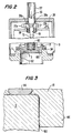
- Figure 2 is a partial cross-sectional side view of the valve shown in Figure 1, illustrating this valve in a closed condition;
- Figure 3 is an enlargement of the valve seat and valve element circled in Figure 2, and
- Figure 4 illustrates the configuration of the opto-interrupters which control the stepper motor of the valve.
-
- With reference now to Figure 1, a preferred embodiment of the motor controlled throttling poppet valve 1 of the invention includes a
cylindrical valve body 3 having a valve seat 5 mounted at its lower end and astepper motor assembly 7 mounted over its upper end. Thevalve body 3 may be formed from stainless steel. The valve body further includes anoutlet port 9 on its side for conducting a flow of a fluid such as a low pressure gas. Centrally disposed within thevalve body 3 is a threaded shaft 11 which reciprocably moves avalve element 13 into sealing engagement and disengagement with the valve seat 5. A resilient linkage assembly 15 having a constant force spring 17 interconnects the lower end of the threaded shaft 11 with thevalve element 13. This assembly 15 functions to forcibly depress thevalve element 13 against the valve seat 5 when the threaded shaft 11 is moved into a valve closing position with substantially the same force regardless of variations in the distance between the free end of the shaft 11 and the valve seat 5 which may occur, for example, as the result of thermal expansion or contraction of the metal forming thecylindrical valve body 3. - The
stepper motor assembly 7 includes a nut driving stepper motor which may be, for example, a model number LA23, LA34 or LA42 stepper motor manufactured by Eastern Air Devices located in Dover, New Hampshire. Preferably, themotor 20 is calibrated to rotate one time upon the receipt of 400 power pulses. Thestepper motor 20 includes a centrally disposedbore 21 for conducting the threaded shaft 11, and afront flange 22 which is attached to amotor mounting plate 24 by means of abolt 25. Thestepper motor 20 is contained within a cylindricallyshaped motor housing 26 having afront mounting flange 28. Thismounting flange 28 is secured anupper flange 32 that circumscribes thevalve body 3 by means of a plurality ofbolts 30, only one of which is shown. - With reference now to Figures 1 and 4, the
motor housing 26 contains an opto-interrupter assembly 33 which is mounted on the top end of thestopper motor 20 by means of a nut andstud 36. The opto-interrupter assembly 33 includes a pair of opto-interrupters 37a,b which are mechanically mounted in parallel as shown in order to minimize the amount of vertical space that the opto-interrupter assembly 33 requires within the upper end of themotor housing 26. Each of the opto-interrupters 37a,b includes anLED window 38a,b and a phototransistor window 39a,b respectively. In both cases, theLED windows 38a,b transmit light from a light-emitting diode contained within its respective opto-interrupter, while the phototransistor window 39a,b will normally receive the light emitted by this LED unless the optical path between the twowindows interrupters 37a may be a model number 0PB901W55 manufactured by Optek located in Carrollton, Texas, while opto-interrupter 37b may be a model 0PB903W55. Opto-interrupter 37a generates a signal ("fires") when the light beam from itsLED window 38a to its phototransistor window 39a is uninterrupted, whereas opto-interrupter 37b fires when its respective light beam is interrupted. Hence the signal of opto-interrupter 37a is inverted relative to opto-interrupter 37b. - The outputs of each of these opto-
interrupters 37a,b is connected to apower control circuit 40 as shown in Figure 4, which in turn regulates the number of power pulses conducted to thestepper motor 20. As is shown in Figures 1 and 4, the center line of the parallelly mounted opto-interrupters 37a,b is offset relative to the center line of the threaded shaft 11 for a purpose which will be explained shortly hereinafter. - The
stepper motor 20 includes adrive nut 41 which is concentrically aligned with its axis of rotation and rotatably mounted near the bottom portion of themotor 20 as shown in Figure 1. Thisdrive nut 41 is engaged with the central threadedportion 43 of the shaft 11. In the preferred embodiment, the threadedportion 43 employs a relatively fine screw pitch (which may be, for example, 0.062 inches per rotation) whose screw threads have a substantially square profile, which is known in the art as an Acme screw thread. The fine pitch of this screw thread, in combination with such a square profile, creates a substantial frictional engagement between the threaded shaft 11 and the screw threads of thedrive nut 41 which advantageously resists any tendency for the threaded shaft 11 to "backdrive" through thenut 41 when pressure on thevalve element 13 applies an upwardly directed axial force to the shaft 11. - The
bottom end 45 of the threaded shaft 11 includes screw threads (not shown) which are screwed into a threaded bore present in thespring guide 62 of the resilient linkage assembly 15. The top end 47 of the threaded shaft 11 includes a threaded bore (not shown) for receiving the bottom, threaded end (again not shown) of an opto-interrupter adjustment screw 49. Thebottom end 51 of the shank of the opto-interrupter adjustment screw is deliberately fabricated to have a reduced diameter portion, while the top end of theadjustment screw 49 includes a screw head 53 with aslot 55 for receiving the blade of a screwdriver. This screw head 53 is contained within ashort guide tube 57 which is screwed into a threaded opening present at the top of themotor housing 26. Finally, abushing 58 is concentrically disposed around the top end of thebore 21 of thestepper motor 20 that accommodates the threaded shaft 11. - With reference again to Figure 1, the resilient linkage assembly 15 includes a generally tubular shaped,
spring retainer 60. The bottom end of thespring retainer 60 is integrally connected to thevalve element 13, while the inner diameter of the top end includesscrew threads 61 for receiving retainingnut 70. A generallycylindrical spring guide 62 is concentrically disposed within thetubular spring retainer 60. Thespring guide 62 includes astroke limiting shoulder 64 at its upper middle portion, and includes a threadedbore 66 at its upper end for receiving the screw threads located at thebottom end 45 of the threaded shaft 11. The previously referred-to retainingnut 70 includes a hexagonal head 71 and a threadedshank 73 whose bottom end engages the top of thestroke limiting shoulder 64 when the head of the nut 71 is screwed into engagement with the top end of thetubular spring retainer 60 as shown. Such screwing down of the retainingnut 70 advantageously pre-compresses the constant force helical spring 17 while at the same time defining a relatively short spring stroke S whose length is the distance between the bottom end of thespring guide 62, and the top surface of thevalve element 13. To maximize the constant force characteristics of the spring 17, the length of the threadedshank 73 of the retainingnut 70 is chosen to define a spring stroke which is only a little larger than the maximum expected variation of the distance between theupper surface 98 of the valve seat 5, and thevalve element 13 when the threaded shaft 11 assumes a valve closing position as a result of thermal expansion or contraction of the metal forming thecylindrical valve body 3, in addition to whatever dimensional variations may occur as a result of the inadvertent deposition of thin films over thetop surface 98 of the valve seat 5. In the context of this specification, a constant force spring may be, for example, a spring whose compressive force characteristics vary less than 10% over the stroke of the spring. - The resilient linkage assembly 15 is circumscribed by
guide sleeve 75 which projects down from themotor mounting plate 24. A teflon-coatedsteel bushing 77 is disposed between the inner diameter of theguide sleeve 75, and the outer diameter of thespring retainer 60 of the resilient linkage assembly 15 in order to minimize friction therebetween when the threaded shaft 11 reciprocably and slidably moves the resilient linkage assembly 15 along the axis of rotation of theguide sleeve 75. - A metallic, tubular bellows 79 completely surrounds and hermetically seals the resilient linkage assembly 15 from the interior portion of the
cylindrical valve body 3 which will conduct gases during the operation of the valve in order to insure that any particulate matter generated by the moving parts of the linkage assembly 15 will not ultimately find their way into the vacuum system that the valve 1 forms a part of. The lower end of thebellows 79 circumscribes aflange 81 that extends from the upper side of thevalve element 13, while the upper end of thebellows 79 is circumferentially connected to abellows mounting plate 83 which defines the ceiling of thevalve body 3. A sealinggasket 85 forms a gas tight seal between the outer edge of thebellows mounting plate 83, and anannular groove 87 in the inner diameter of the upper mountingflange 32 of thevalve body 3. Thebellows mounting plate 83 advantageously defines a vent path between the interior of thebellows 79 and the ambient atmosphere which is formed from anannular vent space 89 located around the inner diameter of theplate 83, and radially orientedvent spaces 91 defined between the upper surface of thebellows mounting plate 83, and the lower surface of themotor mounting plate 24. The bellows 79 advantageously biases the threaded shaft 11 against the threads of thedrive nut 41 as a result of both spring-type mechanical spring forces that the pleats of thebellows 79 apply to the upper side of thevalve element 13, as well as pneumatic forces created by the fact that the pressure within thebellows 79 is at ambient, while the pressure within thevalve body 3 is typically below ambient or at near vacuum. The biasing forces that thebellows 79 applies between the threaded shaft 11 and thedrive nut 41 advantageously prevent backlash from occurring between these two threaded components which could in turn cause the linear displacement of the threaded shaft 11 to disadvantageously vary with the number of rotations of thedrive nut 41. - With reference now to Figures 1 and 3, the
valve element 13 preferably includes an 0-ring 94 formed from an elastomeric material which is disposed in anannular groove 96 which circumscribes the outer portion ofvalve element 13. The provision of such an O-ring in thevalve element 13 advantageously provides positive, complete and reliable shut-off characteristics to the valve 1. While an O-ring 94 is used in this particular preferred embodiment, any sealing element (such as an elastomeric gasket or a copper seal of the type typically used in high vacuum applications) is within the scope of the invention. When the threaded shaft 11 is moved into a valve closing position by thestepper motor 20, the O-ring 94 sealingly engages a flat,annular surface 98 located on the top surface of the valve seat 5. Thevalve element 13 is further provided with acylindrical nose piece 100 which is substantially complementary in shape to the cylindricalinner diameter 102 of the valve seat 5, but spread apart from the diameter by a thinannular space 103. - In operation, when the threaded shaft 11 assumes the valve opening position illustrated in Figure 1, neither of the beams of the opto-
interrupters 37a,b is interrupted by any portion of theadjustment screw 49. Because the outputs of the opto-interrupters 37a,b are inverted relative to one another, 37a generates no signal at the valve opening position, while 37b generates a firing signal. Thepower control circuit 40 is programmed to cease sending pulses of power to thestepper motor 20 upon receipt of a firing signal from one of the opto-interrupters 37a,b. When the operator of the valve 1 overrides the "cease power" output of thepower control circuit 40 to extend the threaded shaft 11 into a valve closing position, thedrive nut 41 of thestepper motor 20 continues to move thevalve element 13 down toward the valve seat 5. Because of the offset relationship between the shank of theadjustment screw 49 and the interface 37.5 of the opto-interrupters 37a,b, the light beam of 37a remains uninterrupted, while the beam of 37b is interrupted. Thus neither opto-interrupter "fires", and themotor 20 is free to rotate until the lower portion of the screw head 53 interrupts the beams of both of the opto-interrupters 37a,b as is shown in Figure 2, at which time opto-interrupter 37b generates a firing signal that causes thepower control circuit 40 to cease transmitting power to themotor 20. At this juncture, the O-ring 94 of thevalve element 13 is compressed against the flat,annular surface 98 of the valve seat 5 in the position illustrated in both Figures 2 and 3. As has been indicated previously, the extent to which the bottom end of theadjustment screw 49 of the opto-interrupter assembly 33 can be screwed into the top end 47 of the threaded shaft 11 is variable due to the presence of screw threads (not shown) extending from the bottom portion of thesmall end 51 of thescrew 49. In the preferred method of operating the valve 1, theadjustment screw 49 is screwed into the top end 47 of the threaded shank 11 to an extent such that when the O-ring 94 engages the flatannular surface 98 of the valve seat 5, the spring 17 will be compressed a distance of 1/2 of its stroke S (as may be seen by comparing the distance between the bottom end of thespring guide 62 and the upper surface of thevalve element 13 in Figures 1 and 2). The adjustment of thescrew 49 in the aforementioned manner allows the resilient linkage assembly 15 to depress thevalve element 13 against the valve seat 5 with substantially the same force whether thevalve body 3 of the valve 1 expands or contracts in response to ambient temperature conditions, or whether the valve seat 5 becomes inadvertently coated with a film of material. - When the operator of the valve 1 wishes to open the valve pursuant to either a slow start or a throttling operation, he may raise the
valve element 13 with respect to the valve seat 5 with extreme precision by utilizing thepower control circuit 40 to regulate the number of pulses of power transmitted to thestepper motor 20. As thedrive nut 41 of thestepper motor 20 begins to incrementally withdraw thevalve element 13 from the valve seat 5 to an extent where the O-ring 94 is lifted into non-sealing engagement with theannular surface 98, the amount of gas flow conducted by the valve 1 becomes a function of the height h of the annular space 103 (Figure 3) defined between the outer diameter of thenose piece 100, and the inner diameter of thevalve seat 102. When the operator of the valve wishes to completely open the valve 1, thepower control circuit 40 continues to apply power pulses to thestepper motor 20 untilsmall end 51 of theadjustment screw 49 allows both of the opto-interrupters 37a,b to transmit their beams to their respective phototransistors in an uninterrupted state, whereupon thepower control circuit 40 will cease transmitting power pulses to thestepper motor 20, as previously described. - It should be noted that the offset relationship between the center line of the
adjustment screw 49 and the mechanical interface of the two opto-interrupters 37a,b, in combination with the use of opto-interrupters that produce complementary signals form the equivalent of a simple, reliable "and" type control gate which in turn allows the use of a very simplepower control circuit 40.
Claims (13)
- A motor controlled poppet valve including a valve body (3), a valve seat (5), and a valve element (13) which can be reciprocally moved into sealing engagement and disengagement with the valve seat (5), said poppet valve comprising :a threaded shaft (11) driven by a stepper motor (20) through a drive means (41) that threadedly engages said shaft to reciprocally move an end (45) of said shaft into a valve closing and a valve opening position, said valve closing position corresponding to a substantially nonvarying distance between said shaft end and said motor, anda resilient linkage assembly (15) interconnecting said end of said shaft (11) with said valve element (13) for forcibly depressing said valve element in sealing engagement with said valve seat (5) when said shaft is moved into said valve closing position with a force that remains substantially constant regardless of variations in the distance between the end of the shaft and the valve seat (5), said linkage assembly includes a constant force spring (17), characterized in that said linkage assembly (15) includes a generally tubular shaped spring retainer (60) the bottom end of which is connected to the valve element (13) for both retaining said spring in a pre-compressed state and for defining a predetermined stroke (S) of said spring (17).
- A motor controlled poppet valve according to claim 1, wherein the threaded engagement between the shaft (11) and the drive means (41) causes most of the torque generated by the stepper motor (20) to be dissipated in overcoming the frictional forces between said shaft threads and said drive means to prevent backdrive of the threaded shaft with respect to the drive means.
- A motor controlled poppet valve according to claim 2, wherein the drive means includes a rotating nut (41).
- A motor controlled poppet valve according to claim 1, further comprising a bellows (79) for containing and isolating said resilient linkage assembly (15) within said valve body (3).
- A motor controlled poppet valve according to claim 1, further comprising a means (79) for applying a biasing force between the threads of said shaft (11) and said drive means (41) to prevent backlash.
- A motor controlled poppet valve according to claim 5, wherein said biasing means includes a bellows (79) that further functions to contain and isolate said resilient linkage assembly (15).
- A motor controlled poppet valve according to claim 1, wherein said valve element (13) further includes a sealing element (94), and a member (100) that is substantially complementary in shape to at least a portion of said valve seat (5) to provide throttling and soft pump capabilities for said valve.
- A motor controlled poppet valve according to claim 7, wherein said sealing element of said valve element includes a resilient 0-ring (94) in a groove (96) which circumscribes the outer portion of the valve element (13).
- A motor controlled poppet valve according to claim 1, further comprising optical switching means (33) for deactivating said stepper motor (20) when said shaft (11) is moved into said valve closing position.
- A motor controlled poppet valve according to claim 1, further comprising means (49) for adjusting the distance between the end of the shaft (11) and said stepper motor (20) that corresponds to said valve closing position.
- A motor controlled poppet valve according to claims 9 and 10, wherein said adjusting means includes a screw (49) engaged to said threaded shaft (11) for changing the position of the portion of the shaft that said optical switching means (33) interact with.
- A motor controlled poppet valve according to claim 1, wherein the resilient linkage assembly (15) is compressible over the predetermined stroke (S) which corresponds to a distance with respect to the axis of said shaft (11) which is greater than the maximum variation in the distance between the shaft end and the valve seat (5) due to thermal expansion and contraction of said valve body (3).
- A motor controlled poppet valve according to claim 1, further comprising a power control circuit (40) for controlling the number of electrical power pulses of the stepper motor (20), and a pair of opto-interrupters (37a, 37b) mechanically connected in parallel which electrically communicate with the power control circuit (40) and optically communicate with an end (51) of the threaded shaft (11) to stop and start the stepper motor (20) when said threaded shaft is in said valve opening and valve closing positions.
Applications Claiming Priority (3)
| Application Number | Priority Date | Filing Date | Title |
|---|---|---|---|
| US896844 | 1992-06-12 | ||
| US07/896,844 US5318272A (en) | 1992-06-12 | 1992-06-12 | Motor controlled throttling poppet valve |
| PCT/US1993/005515 WO1993025832A1 (en) | 1992-06-12 | 1993-06-14 | Motor controlled throttling poppet valve |
Publications (3)
| Publication Number | Publication Date |
|---|---|
| EP0598894A1 EP0598894A1 (en) | 1994-06-01 |
| EP0598894A4 EP0598894A4 (en) | 1994-08-31 |
| EP0598894B1 true EP0598894B1 (en) | 2001-01-10 |
Family
ID=25406943
Family Applications (1)
| Application Number | Title | Priority Date | Filing Date |
|---|---|---|---|
| EP93915265A Expired - Lifetime EP0598894B1 (en) | 1992-06-12 | 1993-06-14 | Motor controlled throttling poppet valve |
Country Status (5)
| Country | Link |
|---|---|
| US (1) | US5318272A (en) |
| EP (1) | EP0598894B1 (en) |
| JP (1) | JP2662312B2 (en) |
| DE (1) | DE69329847T2 (en) |
| WO (1) | WO1993025832A1 (en) |
Families Citing this family (39)
| Publication number | Priority date | Publication date | Assignee | Title |
|---|---|---|---|---|
| US5560586A (en) * | 1994-05-25 | 1996-10-01 | Anelva Corporation | Main valve |
| US5518015A (en) * | 1994-09-30 | 1996-05-21 | Gas Research Institute | Automatic calibrating electrically controlled diaphragm valve actuators and methods for their calibration |
| JP2677536B2 (en) * | 1995-09-01 | 1997-11-17 | シーケーディ株式会社 | Vacuum pressure control system |
| US5727776A (en) * | 1996-02-09 | 1998-03-17 | Dana Corporation | Fluid control valve |
| GB2327742B (en) | 1997-07-25 | 2001-12-12 | Denso Corp | Flow control valve |
| US20080073610A1 (en) * | 1997-08-22 | 2008-03-27 | Manning Casey P | Stopcock valve |
| GB9804047D0 (en) | 1998-02-27 | 1998-04-22 | Normalair Garrett Ltd | Method of controlling a parameter |
| US6029682A (en) * | 1998-07-24 | 2000-02-29 | Caterpillar Inc. | Rapidly opening electromagnetic valve |
| US6477268B1 (en) * | 1998-11-17 | 2002-11-05 | Industrial Technology Research Institute | Producing transitions between vistas |
| JP3937029B2 (en) * | 1999-03-26 | 2007-06-27 | 株式会社鷺宮製作所 | Motorized valve |
| JP3390708B2 (en) | 1999-11-22 | 2003-03-31 | メガトール株式会社 | Broadband variable conductance valve |
| US6321776B1 (en) | 2000-04-24 | 2001-11-27 | Wayne L. Pratt | Double diaphragm precision throttling valve |
| US6776392B1 (en) * | 2003-04-24 | 2004-08-17 | Control Components, Inc. | Retractable plug assembly |
| US7063304B2 (en) * | 2003-07-11 | 2006-06-20 | Entegris, Inc. | Extended stroke valve and diaphragm |
| JP4247576B2 (en) * | 2004-05-14 | 2009-04-02 | Smc株式会社 | Exhaust valve |
| DE112007001140B4 (en) | 2006-05-08 | 2021-02-18 | Magna Powertrain Fpc Limited Partnership | Vehicle cooling system with directed flows |
| JP2007321873A (en) * | 2006-05-31 | 2007-12-13 | Toshiba Corp | Valve control method |
| CN101126452B (en) * | 2006-08-17 | 2010-10-27 | 上海捷能环保高科技有限公司 | Double magnet attraction superposed type fuel gas motor magnetic-control relief valve |
| EP2331858B1 (en) * | 2008-09-08 | 2013-02-20 | Mecanique Analytique Inc. | Temperature compensated valve for gas chromatography |
| US8636262B2 (en) * | 2009-11-13 | 2014-01-28 | Fisher Controls International, Llc | Coupling apparatus for use with electric actuators |
| JP5053397B2 (en) * | 2010-02-18 | 2012-10-17 | Ckd株式会社 | Electric vacuum valve |
| CN103228964B (en) * | 2010-10-06 | 2016-12-14 | 丹福斯有限公司 | Flow control valve and the method assembling flow control valve |
| DE102010048901A1 (en) * | 2010-10-08 | 2012-04-12 | Ewald Schneider | Electromotive actuated valve |
| US8671987B2 (en) | 2010-12-15 | 2014-03-18 | Mks Instruments, Inc. | Two-stage, slow-start valve apparatus |
| DE102011017263A1 (en) * | 2011-04-15 | 2012-10-18 | Khs Gmbh | filler |
| US8833383B2 (en) | 2011-07-20 | 2014-09-16 | Ferrotec (Usa) Corporation | Multi-vane throttle valve |
| US8979063B2 (en) | 2011-11-28 | 2015-03-17 | Fisher Controls International Llc | Failsafe apparatus for use with linear actuators |
| WO2014126642A1 (en) * | 2013-02-14 | 2014-08-21 | Parker-Hannifin Corporation | Modulating balance ported three way valve |
| US9243553B2 (en) * | 2013-05-16 | 2016-01-26 | Ford Global Technologies, Llc | Electric waste gate control system sensor calibration with end-stop detection |
| JP6756702B2 (en) | 2014-09-01 | 2020-09-16 | ダンフォス アクチ−セルスカブ | Valve with welded valve housing |
| EP3193057A1 (en) * | 2016-01-12 | 2017-07-19 | IMI Hydronic Engineering International SA | Actuator and method for valve type recognition |
| CN105546134A (en) * | 2016-01-29 | 2016-05-04 | 浙江绿洲制冷设备有限公司 | Electronic expansion valve |
| JP6860988B2 (en) * | 2016-07-19 | 2021-04-21 | 株式会社鷺宮製作所 | Electric valve |
| DE102020125944A1 (en) | 2020-10-05 | 2022-04-07 | ECO Holding 1 GmbH | Switching valve with a stepping motor |
| US11668409B2 (en) * | 2020-12-11 | 2023-06-06 | The Digivac Company | Stepper motor proportional control bellows valve |
| JP7680942B2 (en) * | 2021-11-17 | 2025-05-21 | 株式会社キッツエスシーティー | High temperature gate valve |
| US11976734B2 (en) | 2021-12-28 | 2024-05-07 | Mac Valves, Inc. | Proportional flow control valve |
| DE102022000602A1 (en) * | 2022-02-17 | 2023-08-17 | Vat Holding Ag | Vacuum angle valve with pressure sensor |
| US12104715B2 (en) * | 2022-03-09 | 2024-10-01 | Pfeiffer Vacuum Technology AG | Vacuum valve |
Family Cites Families (8)
| Publication number | Priority date | Publication date | Assignee | Title |
|---|---|---|---|---|
| US2331503A (en) * | 1942-05-26 | 1943-10-12 | William A Ray | Fluid control valve |
| US4185699A (en) * | 1978-04-07 | 1980-01-29 | Dynamics Corporation Of America | Soil contact tool |
| US4184333A (en) * | 1978-06-30 | 1980-01-22 | Towmotor Corporation | Fluid power system |
| US4412517A (en) * | 1980-10-06 | 1983-11-01 | Toyota Jidosha Kogyo Kabushiki Kaisha | Idling speed control device of an internal combustion engine |
| US4815699A (en) * | 1987-12-21 | 1989-03-28 | Sundstrand Corporation | Valve with resilient, bellows mounted valve seat |
| JPH01295085A (en) * | 1988-05-20 | 1989-11-28 | Kimura Koki Kk | Proportional electrically driven two-way valve |
| JP3117175B2 (en) * | 1994-02-09 | 2000-12-11 | アルプス電気株式会社 | Resistor |
| JP3117175U (en) | 2005-01-31 | 2006-01-05 | 博美 轟 | Cash tray type bill watermark confirmation machine |
-
1992
- 1992-06-12 US US07/896,844 patent/US5318272A/en not_active Expired - Lifetime
-
1993
- 1993-06-14 DE DE69329847T patent/DE69329847T2/en not_active Expired - Lifetime
- 1993-06-14 WO PCT/US1993/005515 patent/WO1993025832A1/en not_active Ceased
- 1993-06-14 EP EP93915265A patent/EP0598894B1/en not_active Expired - Lifetime
- 1993-06-14 JP JP6501694A patent/JP2662312B2/en not_active Expired - Lifetime
Also Published As
| Publication number | Publication date |
|---|---|
| EP0598894A4 (en) | 1994-08-31 |
| EP0598894A1 (en) | 1994-06-01 |
| JP2662312B2 (en) | 1997-10-08 |
| JPH06509861A (en) | 1994-11-02 |
| DE69329847D1 (en) | 2001-02-15 |
| US5318272A (en) | 1994-06-07 |
| DE69329847T2 (en) | 2001-07-19 |
| WO1993025832A1 (en) | 1993-12-23 |
Similar Documents
| Publication | Publication Date | Title |
|---|---|---|
| US5318272A (en) | Motor controlled throttling poppet valve | |
| KR102859810B1 (en) | Proportional flow control valve poppet with flow control needle | |
| US5215286A (en) | High pressure diaphragm valve | |
| US3926208A (en) | Pressure regulator | |
| KR101546984B1 (en) | In-line adjustable regulator | |
| EP0322406B1 (en) | Bellows valve | |
| US6321780B1 (en) | Valve for controlling flow rate of gas | |
| AU2012362670B2 (en) | Mounting assemblies for use with fluid control devices | |
| US3982729A (en) | Back-up seal for diaphragm valve | |
| US6843266B2 (en) | Regulator with erosion resistant seal assemblies | |
| CA2469418C (en) | Pneumatic pressure regulator assembly | |
| US4314582A (en) | Combined pressure-regulator and manual shut-off valve | |
| EP0345913B1 (en) | Valve override mechanism | |
| AU592442B2 (en) | Improved safety relief valve | |
| US6095193A (en) | Smooth vent valve | |
| US6279607B1 (en) | Fluid metering valve | |
| US3540471A (en) | Speed control valve | |
| CA2066962A1 (en) | Externally adjustable flow restriction control for poppet valves | |
| JP3347960B2 (en) | Control valve | |
| WO1990014538A1 (en) | Finely-adjustable flow control valve | |
| US4736767A (en) | Fluid flow controller | |
| HK1077647B (en) | Pneumatic pressure regulator assembly | |
| HK40024939A (en) | Proportional flow control valve poppet with flow control needle |
Legal Events
| Date | Code | Title | Description |
|---|---|---|---|
| PUAI | Public reference made under article 153(3) epc to a published international application that has entered the european phase |
Free format text: ORIGINAL CODE: 0009012 |
|
| 17P | Request for examination filed |
Effective date: 19940209 |
|
| AK | Designated contracting states |
Kind code of ref document: A1 Designated state(s): CH DE FR GB LI |
|
| RHK1 | Main classification (correction) |
Ipc: F16K 31/04 |
|
| A4 | Supplementary search report drawn up and despatched | ||
| AK | Designated contracting states |
Kind code of ref document: A4 Designated state(s): CH DE FR GB LI |
|
| 17Q | First examination report despatched |
Effective date: 19980804 |
|
| GRAG | Despatch of communication of intention to grant |
Free format text: ORIGINAL CODE: EPIDOS AGRA |
|
| GRAG | Despatch of communication of intention to grant |
Free format text: ORIGINAL CODE: EPIDOS AGRA |
|
| GRAH | Despatch of communication of intention to grant a patent |
Free format text: ORIGINAL CODE: EPIDOS IGRA |
|
| GRAH | Despatch of communication of intention to grant a patent |
Free format text: ORIGINAL CODE: EPIDOS IGRA |
|
| GRAA | (expected) grant |
Free format text: ORIGINAL CODE: 0009210 |
|
| AK | Designated contracting states |
Kind code of ref document: B1 Designated state(s): CH DE FR GB LI |
|
| REG | Reference to a national code |
Ref country code: CH Ref legal event code: EP |
|
| REF | Corresponds to: |
Ref document number: 69329847 Country of ref document: DE Date of ref document: 20010215 |
|
| REG | Reference to a national code |
Ref country code: CH Ref legal event code: NV Representative=s name: BOVARD AG PATENTANWAELTE |
|
| ET | Fr: translation filed | ||
| PLBE | No opposition filed within time limit |
Free format text: ORIGINAL CODE: 0009261 |
|
| STAA | Information on the status of an ep patent application or granted ep patent |
Free format text: STATUS: NO OPPOSITION FILED WITHIN TIME LIMIT |
|
| REG | Reference to a national code |
Ref country code: GB Ref legal event code: IF02 |
|
| 26N | No opposition filed | ||
| REG | Reference to a national code |
Ref country code: CH Ref legal event code: PFA Owner name: MKS INSTRUMENTS, INC. Free format text: MKS INSTRUMENTS, INC.#SIX SHATTUCK ROAD#ANDOVER MASSACHUSETTS 01810 (US) -TRANSFER TO- MKS INSTRUMENTS, INC.#SIX SHATTUCK ROAD#ANDOVER MASSACHUSETTS 01810 (US) |
|
| PGFP | Annual fee paid to national office [announced via postgrant information from national office to epo] |
Ref country code: CH Payment date: 20120625 Year of fee payment: 20 Ref country code: DE Payment date: 20120627 Year of fee payment: 20 |
|
| PGFP | Annual fee paid to national office [announced via postgrant information from national office to epo] |
Ref country code: GB Payment date: 20120625 Year of fee payment: 20 Ref country code: FR Payment date: 20120705 Year of fee payment: 20 |
|
| REG | Reference to a national code |
Ref country code: DE Ref legal event code: R071 Ref document number: 69329847 Country of ref document: DE |
|
| REG | Reference to a national code |
Ref country code: CH Ref legal event code: PL |
|
| REG | Reference to a national code |
Ref country code: GB Ref legal event code: PE20 Expiry date: 20130613 |
|
| PG25 | Lapsed in a contracting state [announced via postgrant information from national office to epo] |
Ref country code: DE Free format text: LAPSE BECAUSE OF EXPIRATION OF PROTECTION Effective date: 20130615 Ref country code: GB Free format text: LAPSE BECAUSE OF EXPIRATION OF PROTECTION Effective date: 20130613 |