EP0598888B1 - Channel re-assignment method for time division multiple access (tdma) trunked systems - Google Patents
Channel re-assignment method for time division multiple access (tdma) trunked systems Download PDFInfo
- Publication number
- EP0598888B1 EP0598888B1 EP93914221A EP93914221A EP0598888B1 EP 0598888 B1 EP0598888 B1 EP 0598888B1 EP 93914221 A EP93914221 A EP 93914221A EP 93914221 A EP93914221 A EP 93914221A EP 0598888 B1 EP0598888 B1 EP 0598888B1
- Authority
- EP
- European Patent Office
- Prior art keywords
- communication
- assigned
- slot
- time
- resource
- Prior art date
- Legal status (The legal status is an assumption and is not a legal conclusion. Google has not performed a legal analysis and makes no representation as to the accuracy of the status listed.)
- Expired - Lifetime
Links
- 238000000034 method Methods 0.000 title claims abstract description 19
- 238000004891 communication Methods 0.000 claims abstract description 97
- 230000005540 biological transmission Effects 0.000 claims abstract description 61
- 238000010586 diagram Methods 0.000 description 4
- 238000005259 measurement Methods 0.000 description 3
- 230000000977 initiatory effect Effects 0.000 description 2
- 238000012544 monitoring process Methods 0.000 description 2
- 230000011664 signaling Effects 0.000 description 2
- 230000003466 anti-cipated effect Effects 0.000 description 1
- 230000015556 catabolic process Effects 0.000 description 1
- 238000006731 degradation reaction Methods 0.000 description 1
- 230000000694 effects Effects 0.000 description 1
- 230000002123 temporal effect Effects 0.000 description 1
Images


Classifications
-
- H—ELECTRICITY
- H04—ELECTRIC COMMUNICATION TECHNIQUE
- H04J—MULTIPLEX COMMUNICATION
- H04J3/00—Time-division multiplex systems
- H04J3/17—Time-division multiplex systems in which the transmission channel allotted to a first user may be taken away and re-allotted to a second user if the first user becomes inactive, e.g. TASI
-
- H—ELECTRICITY
- H04—ELECTRIC COMMUNICATION TECHNIQUE
- H04W—WIRELESS COMMUNICATION NETWORKS
- H04W52/00—Power management, e.g. Transmission Power Control [TPC] or power classes
- H04W52/04—Transmission power control [TPC]
- H04W52/38—TPC being performed in particular situations
- H04W52/50—TPC being performed in particular situations at the moment of starting communication in a multiple access environment
-
- H—ELECTRICITY
- H04—ELECTRIC COMMUNICATION TECHNIQUE
- H04W—WIRELESS COMMUNICATION NETWORKS
- H04W72/00—Local resource management
- H04W72/30—Resource management for broadcast services
-
- H—ELECTRICITY
- H04—ELECTRIC COMMUNICATION TECHNIQUE
- H04W—WIRELESS COMMUNICATION NETWORKS
- H04W28/00—Network traffic management; Network resource management
- H04W28/16—Central resource management; Negotiation of resources or communication parameters, e.g. negotiating bandwidth or QoS [Quality of Service]
- H04W28/26—Resource reservation
-
- H—ELECTRICITY
- H04—ELECTRIC COMMUNICATION TECHNIQUE
- H04W—WIRELESS COMMUNICATION NETWORKS
- H04W72/00—Local resource management
- H04W72/04—Wireless resource allocation
-
- H—ELECTRICITY
- H04—ELECTRIC COMMUNICATION TECHNIQUE
- H04W—WIRELESS COMMUNICATION NETWORKS
- H04W76/00—Connection management
- H04W76/30—Connection release
-
- H—ELECTRICITY
- H04—ELECTRIC COMMUNICATION TECHNIQUE
- H04W—WIRELESS COMMUNICATION NETWORKS
- H04W84/00—Network topologies
- H04W84/02—Hierarchically pre-organised networks, e.g. paging networks, cellular networks, WLAN [Wireless Local Area Network] or WLL [Wireless Local Loop]
- H04W84/04—Large scale networks; Deep hierarchical networks
- H04W84/08—Trunked mobile radio systems
Definitions
- the invention relates, in general, to radio communication systems, and in particular, to communication systems which employ a time division multiple access (TDMA) signalling protocol.
- TDMA time division multiple access
- Trunked radio frequency (RF) communication systems are well known in the art.
- a plurality of subscribers e.g., mobiles, portables, consoles
- channels are typically assigned to requesting subscribers by a communication resource controller, which request and assignment are exchanged via a common control channel.
- the controller might assign a channel to an individual subscriber for a single transmission such that, at the end of the subscriber's transmission, the channel is re-assigned to another subscriber (i.e., so-called transmission trunking).
- the controller might assign a channel to a group of subscribers for engaging in a conversation, and keep the channel assignment active until completion of, or a substantial pause in, the conversation. That is, the assigned channel is not made available for re-assignment until the end of the conversation is anticipated.
- a conversation may include multiple transmissions from multiple subscribers and is referred to in the art as a message. Accordingly, this form of channel assignment is referred to as message trunking.
- Prior art systems have attempted to offer message trunked services by appending a time delay, known as the "hang-time", to the end of each subscriber transmission.
- the controller extends the assignment (i.e., leaves it open for another subscriber belonging to the group who wishes to transmit) for a predetermined period, or so-called hang-time. If no new transmission is begun by the completion of the hang-time, the system controller terminates the channel assignment. As long as the time intervals between successive transmissions are less than the hang-time, message trunking is effectuated.
- the communication controller typically receives transmissions from multiple subscribers.
- Each transmission may exhibit substantially different transmission characteristics, e.g., propagation delay, power level, etc.. These differences are at least partially due to the subscribers being located at substantially different distances from the communications controller.
- Today's message trunked communication e.g., frequency division multiplex (FDM) systems, simply accept each new transmission, and its associated transmission characteristics. Accordingly, the prior art method for accomplishing message trunking works well only for systems which are relatively robust with respect to differences in transmission characteristics between multiple subscribers. A new method is required for systems which are more sensitive to differences in subscriber transmission characteristics.
- FDM frequency division multiplex
- Time-slots 103 occurring periodically in time frames 101, constitute the communication channels of interest.
- the controller assigns a channel (i.e., time-slot) to a group of subscribers to enable a conversation among subscribers belonging to the group. That is, group members communicate (i.e., transmit and receive) information among themselves using the assigned time-slot.
- group members communicate (i.e., transmit and receive) information among themselves using the assigned time-slot.
- the timing of each subscriber transmission in a TDMA system must be strictly controlled to avoid interference among subscribers transmitting on adjacent time-slots. In particular, even slight differences in transmission parameters, e.g., propagation delay, power level, cause an undesirable level of inter-slot interference.
- EP-480 505 relates to a system of transmission having a plurality of subscriber terminals in communication with at least two transmitter/receiver stations, exchanging information in a time-multiplexed manner.
- a TDMA system which provides message trunking for group calls, would be an improvement over the prior art. That is, by reserving an assigned time-slot for the group members, and updating transmission parameters for each transmission, a TDMA radio system would not be constrained by foregoing limitations of today's systems.
- the communications resource takes the form of a particular set of slots on a time-division multiplexed (TDM) radio channel.
- TDM time-division multiplexed
- FIG 1 The structure of the TDM radio channel is shown in FIG 1.
- uplink 100 i.e.,. transmitted from the subscriber to the central controller
- downlink 102 i.e.,. transmitted from the central controller to the subscriber
- Uplink 100 is divided into time-slots 103, and a particular number of slots are grouped together into frames 101 (e.g., four slots in each frame, as shown in FIG. 1) and indicated by the numbering of the time-slots.
- the number of communications resources available on the TDM radio channel is equal to the number of time-slots in each frame. Similar to uplink 100, downlink 102 is divided into time-slots 106, and slots are grouped together into frames 104. In general, the uplink 100 and downlink 102 signals are partitioned in like manner (i.e., same number of time-slots per frame).
- FIG. 2 shows a more detailed view of the information contained in a particular downlink slot 106 as it might appear in two configurations.
- Each downlink slot 106 contains a slot descriptor block 201.
- the slot descriptor block includes a configuration code field 202, which field indicates a present configuration of the slot (i.e., user traffic, reserved, or unassigned configuration).
- Configuration 203 shows downlink slot 106 as it might be configured for user traffic, while configuration 204 shows the same downlink slot as it might be configured in both the reserved and unassigned modes, as later described.
- slot descriptor 201 In user traffic configuration (i.e., configuration 203), slot descriptor 201 contains a user identifier (ID) 205, transmission parametric data field 206, and user data field 208. In the reserved and unassigned configurations (i.e., configuration 204), slot descriptor 201 contains only the appropriate configuration code (e.g., "001" for reserved, and "000” for unassigned), while the remainder of the time-slot is unused. In a preferred embodiment, the radio system controller modifies slot descriptor 201 in downlink slot 106 to control the use of the time-slot as a communications resource, as shown by way of example using FIG. 3.
- ID user identifier
- transmission parametric data field 206 In the reserved and unassigned configurations (i.e., configuration 204), slot descriptor 201 contains only the appropriate configuration code (e.g., "001" for reserved, and "000” for unassigned), while the remainder of the time-slot is unused.
- the first slot of each frame is assigned to a particular communications group for use in participating in a conversation.
- a first member of the group might be transmitting user data (301) into the assigned uplink slot, which is enabled by downlink slots being set to user traffic configuration (303).
- user data also appears on the assigned downlink slot, as previously described using FIG. 2 (i.e., field 208).
- Downlink user data signals are subsequently received by the transmitting unit as well as the remaining units of the communications group.
- the controller Prior to allowing a transmission, the controller updates the slot descriptor field (i.e., 201 shown in FIG. 2) of the downlink slot with information that is required for proper operation of the transmitting unit. That is, user ID field 205 identifies the transmitting unit whose right it is to now transmit into the assigned uplink slot 301. Slot descriptor field 201 also serves to convey the pertinent transmission parameters for the transmitting unit.
- transmission parameter field 206 which may be either a time advance value and/or a power level value as later described, is used to ensure that the uplink transmission does not interfere with adjacent channels (i.e., time-slots).
- a time advance value is written to transmission parameter field 206, and is used to convey to the transmitting unit an amount of time it must advance, or delay, each of its uplink transmissions. This parameter is necessary to ensure that the transmissions arrive at the controller at the proper time despite the effects of propagation delay in the radio channel.
- the time advance value is based on a measurement made by the controller on the request-to-transmit signal received from a unit wishing to transmit on the next available time-slot.
- a power control value instructs the transmitting unit as to the correct power level to use on the uplink transmission, such that the transmissions arrive at the controller with sufficient, bat not excessive, power to avoid undesired interference.
- time advance value which is conveyed to the transmitting unit
- power control value is also contemplated by the present invention.
- a communication unit which is able to detect its own transmission parameter (e.g., time advance value, power control value) is contemplated by the present invention.
- the transmitting unit when it completes the data transmission (e.g., voice data), it transmits a disconnect signal on a subsequent uplink time-slot (e.g., uplink slot 304).
- a disconnect signal could be replaced with any predetermined indicia, provided the controller was configured to recognize it.
- the controller responds to the disconnect signal by re-configuring the assigned slot to create a reserved time-slot.
- the controller indicates this to members of the communications group by setting the configuration code (i.e., field 202) in the downlink slot to "reserved", as depicted in downlink time-slots 305.
- the slot is thereafter available, at least for a predetermined time as later described, to group members wishing to participate in the conversation (in a preferred embodiment, this includes the member who just completed a transmission). Until a group member transmits such a request, the assigned slot is empty, as depicted in uplink time-slots 306.
- Uplink time-slot 307 depicts a request-to-transmit signal being transmitted by a requesting group unit.
- the request-to-transmit contains a requestor identification, which allows the controller to determine which unit is making the request. (It should be noted since the requesting unit does not yet have the required information regarding propagation delay for its transmissions, the duration of the request to transmit signal, is preferably slightly shorter than the duration of the uplink slot This insures that the transmission does not interfere with the neighboring slots in spite of the unknown propagation delay.)
- the controller might derive several transmission parameters from the request-to-transmit sent by the requesting unit.
- the controller might measure the temporal position of the transmission, from which it determines a propagation delay characteristic of the requesting unit, and derive from that measurement a time advance value which applies to the requesting unit. Further, it might measure the received power level of the transmission, from which it derives a power control value which applies to the requesting unit. In either case, or in the case where the requesting unit might utilize both parameters to optimize its transmissions, the transmission parameters are conveyed to the requesting unit on a subsequent downlink slot.
- the controller In response to a valid request-to-transmit, the controller re-configures the assigned slot by setting the slot descriptor in the downlink slot to a user traffic configuration code.
- the controller updates the fields of the slot descriptor with the correct requestor ID, and transmission parameters(s). This information is conveyed to the requesting unit via the slot descriptor fields of the downlink slots 308, allowing the requesting unit to commence its user data transmission in subsequent time-slot 309. This sequence completes the preferred cycle, in accordance with the present invention.
- FIG. 4 shows a flow diagram 400 depicting the operation of the radio communication system controller, in a preferred embodiment of the invention.
- the controller assigns (402) a TDM time-slot to a group of communication units, thereby establishing one member of the group as the transmitting unit.
- the controller then waits (404) until a disconnect is received from the transmitting unit, indicating completion of its transmission.
- the controller configures (406) the assigned slot as a reserved slot, and waits (408), for a predetermined time as later described, to receive a valid request-to-transmit from a second, or the same, member of the group.
- the controller measures (410) the appropriate transmission parameters (e.g., propagation delay characteristic, power level), from which it calculates a time advance and/or power control value.
- the controller then re-configures (412) the assigned slot to facilitate the request. That is, the controller changes the configuration code field to "user-traffic", and updates the user id and transmission parameter fields of the downlink slot (e.g., slot 203 of FIG. 2) to reflect the appropriate data for the requesting unit.
- These parameters are conveyed to all group members, allowing the requesting unit to respond, as later described using FIG. 5, by transmitting a message to the rest of the group.
- the controller then returns; waiting (404) to receive a disconnect from the new transmitting unit.
- the controller determines (414) whether or not a so-called "hang-time" has expired.
- the hang-time is simply a predetermined amount of time during which a group member may respond, via the reserved slot, before the slot is released to other system users. In a preferred embodiment, the hang-time ranges from one to 10 seconds, but other durations might be suitable, depending on system loading and typical message durations. If no request is received before the hang-time expires, the controller releases (416) the assigned/reserved slot by changing the configuration code to "unassigned", as depicted in slot 204 of FIG. 2.
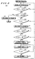
- FIG. 5 shows a flow diagram depicting the operation of a communication group unit, in accordance with the present invention.
- FIG. 5 depicts the operation of a communication unit which is initially not the transmitting unit, but rather a group member monitoring a call.
- the unit decodes (501) the downlink slot information.
- the unit continues to evaluate the configuration code of the downlink slot until the configuration is no longer "user traffic". That is, so long as the configuration code remains "user traffic", the unit will continue to decode (501) the downlink slot information.
- the unit determines (505) whether or not the slot has been configured as "unassigned”. If so, the unit reverts to monitoring (507) the control resource (e.g., another slot) and the routine is exited.
- the control resource e.g., another slot
- the unit determines (509) whether or not the user has asserted push-to-talk (PTT), which would indicate that the group unit wishes to become the transmitting unit. If PTT has not been asserted, the unit continues to decode (501) slot information, as before. If PTT has been asserted, the unit tries to acquire the right to transmit by sending (511) a request-to-transmit on the uplink slot. The unit then continuously checks (513) for the configuration code to change to "traffic", indicating that a valid request-to-transmit was received by the controller.
- PTT push-to-talk
- the unit checks (515) the user ID field in the slot descriptor to see if it matches its own ID. If not, i.e., another unit has become the transmitting unit, the unit returns to decode (501) slot information. If the user ID field matches that of the unit, the unit determines (517) its present transmission parameter(s) (i.e., by reading the appropriate field in the slot descriptor block to obtain its time advance and/or power control values). Once it has been determined that the unit has the right to transmit on the assigned/reserved slot, the unit transmits (519) user data into the uplink slot, while continuously checking (521) for the PTT to be released. Upon release of the PTT, the unit sends (523) a disconnect signal on the uplink slot, and returns to decoding (501) downlink slot information.
- members of a communication group may exchange messages, via a single time-slot, until a conversation has been completed. That is, by reserving the assigned time-slot for a predetermined time (i.e., hang-time), the radio communication system can make efficient use of the limited communication resources available to users. Further, the TDMA system controller is able to maintain high volumes of group calls, using the aforementioned analogy to message-trunking, while sustaining superior levels of performance through reduced interference among adjacent time-slots.
Landscapes
- Engineering & Computer Science (AREA)
- Computer Networks & Wireless Communication (AREA)
- Signal Processing (AREA)
- Mobile Radio Communication Systems (AREA)
- Time-Division Multiplex Systems (AREA)
- Radio Relay Systems (AREA)
Abstract
Description
- The invention relates, in general, to radio communication systems, and in particular, to communication systems which employ a time division multiple access (TDMA) signalling protocol.
- Trunked radio frequency (RF) communication systems are well known in the art. In such systems, a plurality of subscribers (e.g., mobiles, portables, consoles) share a limited number of communication resources, e.g., channels. In particular, channels are typically assigned to requesting subscribers by a communication resource controller, which request and assignment are exchanged via a common control channel. The controller might assign a channel to an individual subscriber for a single transmission such that, at the end of the subscriber's transmission, the channel is re-assigned to another subscriber (i.e., so-called transmission trunking).
- In the alternative, the controller might assign a channel to a group of subscribers for engaging in a conversation, and keep the channel assignment active until completion of, or a substantial pause in, the conversation. That is, the assigned channel is not made available for re-assignment until the end of the conversation is anticipated. A conversation may include multiple transmissions from multiple subscribers and is referred to in the art as a message. Accordingly, this form of channel assignment is referred to as message trunking.
- Subscribers attempting to engage in a conversation on a transmission trunked system are required to execute channel assignment request procedures for each transmission. Such procedures may result in significant transmission delay, particularly if an idle channel is not available at the time of the request. Message trunking eliminates the channel assignments within a conversation. Hence, message trunking presents benefits to the communication system users by allowing conversations to proceed in a more efficient and natural manner.
- Prior art systems have attempted to offer message trunked services by appending a time delay, known as the "hang-time", to the end of each subscriber transmission. In these systems, the controller extends the assignment (i.e., leaves it open for another subscriber belonging to the group who wishes to transmit) for a predetermined period, or so-called hang-time. If no new transmission is begun by the completion of the hang-time, the system controller terminates the channel assignment. As long as the time intervals between successive transmissions are less than the hang-time, message trunking is effectuated.
- During the course of a conversation, the communication controller typically receives transmissions from multiple subscribers. Each transmission may exhibit substantially different transmission characteristics, e.g., propagation delay, power level, etc.. These differences are at least partially due to the subscribers being located at substantially different distances from the communications controller. Today's message trunked communication, e.g., frequency division multiplex (FDM) systems, simply accept each new transmission, and its associated transmission characteristics. Accordingly, the prior art method for accomplishing message trunking works well only for systems which are relatively robust with respect to differences in transmission characteristics between multiple subscribers. A new method is required for systems which are more sensitive to differences in subscriber transmission characteristics.
- Communication systems employing time division multiple access (TDMA) signalling are well known. These systems divide an RF resource into a series of recurring time frames which are further divided into time-slots, as shown in FIG. 1. Time-
slots 103, occurring periodically intime frames 101, constitute the communication channels of interest. As earlier described, the controller assigns a channel (i.e., time-slot) to a group of subscribers to enable a conversation among subscribers belonging to the group. That is, group members communicate (i.e., transmit and receive) information among themselves using the assigned time-slot. Unlike FDM systems, however, the timing of each subscriber transmission in a TDMA system must be strictly controlled to avoid interference among subscribers transmitting on adjacent time-slots. In particular, even slight differences in transmission parameters, e.g., propagation delay, power level, cause an undesirable level of inter-slot interference. - Many known systems control subscriber timing by enabling the controller to measure the arrival time of the received request on the control channel, and adjusting the timing prior to the first transmission on the assigned channel. However, this measurement is only applicable to the subscriber submitting the initial request for a channel assignment. Subsequent transmissions from other group members (i.e., which demonstrate substantial differences in transmission timing from the initiating subscriber) can cause interference with the time-slots adjacent to the assigned time-slot. Similarly, excessive power levels of uplink transmissions may cause interference among adjacent time-slots, resulting in performance degradation. Control of transmission power levels from the initiating subscriber, therefore, would help to enhance system performance.
- EP-480 505 relates to a system of transmission having a plurality of subscriber terminals in communication with at least two transmitter/receiver stations, exchanging information in a time-multiplexed manner.
- Accordingly, there exists a need for a radio communication system which is able to maintain efficient usage of available communication resources, while limiting undesirable interference among those resources. In particular, a TDMA system which provides message trunking for group calls, would be an improvement over the prior art. That is, by reserving an assigned time-slot for the group members, and updating transmission parameters for each transmission, a TDMA radio system would not be constrained by foregoing limitations of today's systems.
-
- FIG. 1 shows a simplified graphical representation of an uplink data frame sequence and a downlink data frame sequence, as is well known in the art.
- FIG. 2 shows a simplified graphical representation of a downlink slot, in accordance with the present invention.
- FIG. 3 shows a simplified graphical representation of an uplink data stream and a downlink data stream, in accordance with the present invention.
- FIG. 4 shows a simplified flow diagram depicting the operation of a radio communication system controller, in accordance with the present invention.
- FIG. 5 shows a simplified flow diagram depicting the operation of a radio communication group unit, in accordance with the present invention.
-
- In a preferred embodiment of the invention, the communications resource takes the form of a particular set of slots on a time-division multiplexed (TDM) radio channel. The structure of the TDM radio channel is shown in FIG 1. In particular, uplink 100 (i.e.,. transmitted from the subscriber to the central controller) and downlink 102 (i.e.,. transmitted from the central controller to the subscriber) signals are transmitted on two frequencies of a particular frequency pair.
Uplink 100 is divided into time-slots 103, and a particular number of slots are grouped together into frames 101 (e.g., four slots in each frame, as shown in FIG. 1) and indicated by the numbering of the time-slots. The number of communications resources available on the TDM radio channel is equal to the number of time-slots in each frame. Similar touplink 100,downlink 102 is divided into time-slots 106, and slots are grouped together intoframes 104. In general, theuplink 100 anddownlink 102 signals are partitioned in like manner (i.e., same number of time-slots per frame). - FIG. 2 shows a more detailed view of the information contained in a
particular downlink slot 106 as it might appear in two configurations. Eachdownlink slot 106 contains aslot descriptor block 201. The slot descriptor block includes aconfiguration code field 202, which field indicates a present configuration of the slot (i.e., user traffic, reserved, or unassigned configuration).Configuration 203 showsdownlink slot 106 as it might be configured for user traffic, whileconfiguration 204 shows the same downlink slot as it might be configured in both the reserved and unassigned modes, as later described. - In user traffic configuration (i.e., configuration 203),
slot descriptor 201 contains a user identifier (ID) 205, transmissionparametric data field 206, anduser data field 208. In the reserved and unassigned configurations (i.e., configuration 204),slot descriptor 201 contains only the appropriate configuration code (e.g., "001" for reserved, and "000" for unassigned), while the remainder of the time-slot is unused. In a preferred embodiment, the radio system controller modifiesslot descriptor 201 indownlink slot 106 to control the use of the time-slot as a communications resource, as shown by way of example using FIG. 3. - Referring to FIG. 3, there is shown an series of
uplink frames 300, and a corresponding series ofdownlink frames 302. In a particular instance, the first slot of each frame is assigned to a particular communications group for use in participating in a conversation. For example, a first member of the group might be transmitting user data (301) into the assigned uplink slot, which is enabled by downlink slots being set to user traffic configuration (303). It should be noted that user data also appears on the assigned downlink slot, as previously described using FIG. 2 (i.e., field 208). Downlink user data signals are subsequently received by the transmitting unit as well as the remaining units of the communications group. - Prior to allowing a transmission, the controller updates the slot descriptor field (i.e., 201 shown in FIG. 2) of the downlink slot with information that is required for proper operation of the transmitting unit. That is,
user ID field 205 identifies the transmitting unit whose right it is to now transmit into the assigneduplink slot 301. Slotdescriptor field 201 also serves to convey the pertinent transmission parameters for the transmitting unit. In particular,transmission parameter field 206, which may be either a time advance value and/or a power level value as later described, is used to ensure that the uplink transmission does not interfere with adjacent channels (i.e., time-slots). - In a preferred embodiment, a time advance value is written to
transmission parameter field 206, and is used to convey to the transmitting unit an amount of time it must advance, or delay, each of its uplink transmissions. This parameter is necessary to ensure that the transmissions arrive at the controller at the proper time despite the effects of propagation delay in the radio channel. The time advance value is based on a measurement made by the controller on the request-to-transmit signal received from a unit wishing to transmit on the next available time-slot. Similarly, a power control value instructs the transmitting unit as to the correct power level to use on the uplink transmission, such that the transmissions arrive at the controller with sufficient, bat not excessive, power to avoid undesired interference. In a preferred embodiment, it is the time advance value which is conveyed to the transmitting unit, but an embodiment which either also, or instead, conveys the power control value is also contemplated by the present invention. Also, it should be noted that a communication unit which is able to detect its own transmission parameter (e.g., time advance value, power control value) is contemplated by the present invention. - In a preferred embodiment, when the transmitting unit completes the data transmission (e.g., voice data), it transmits a disconnect signal on a subsequent uplink time-slot (e.g., uplink slot 304). It should be noted that the disconnect signal could be replaced with any predetermined indicia, provided the controller was configured to recognize it. The controller then responds to the disconnect signal by re-configuring the assigned slot to create a reserved time-slot. The controller indicates this to members of the communications group by setting the configuration code (i.e., field 202) in the downlink slot to "reserved", as depicted in downlink time-
slots 305. The slot is thereafter available, at least for a predetermined time as later described, to group members wishing to participate in the conversation (in a preferred embodiment, this includes the member who just completed a transmission). Until a group member transmits such a request, the assigned slot is empty, as depicted in uplink time-slots 306. - Uplink time-
slot 307 depicts a request-to-transmit signal being transmitted by a requesting group unit. The request-to-transmit contains a requestor identification, which allows the controller to determine which unit is making the request. (It should be noted since the requesting unit does not yet have the required information regarding propagation delay for its transmissions, the duration of the request to transmit signal, is preferably slightly shorter than the duration of the uplink slot This insures that the transmission does not interfere with the neighboring slots in spite of the unknown propagation delay.) - As previously discussed, the controller might derive several transmission parameters from the request-to-transmit sent by the requesting unit. The controller might measure the temporal position of the transmission, from which it determines a propagation delay characteristic of the requesting unit, and derive from that measurement a time advance value which applies to the requesting unit. Further, it might measure the received power level of the transmission, from which it derives a power control value which applies to the requesting unit. In either case, or in the case where the requesting unit might utilize both parameters to optimize its transmissions, the transmission parameters are conveyed to the requesting unit on a subsequent downlink slot.
- In response to a valid request-to-transmit, the controller re-configures the assigned slot by setting the slot descriptor in the downlink slot to a user traffic configuration code. The controller updates the fields of the slot descriptor with the correct requestor ID, and transmission parameters(s). This information is conveyed to the requesting unit via the slot descriptor fields of the downlink slots 308, allowing the requesting unit to commence its user data transmission in subsequent time-
slot 309. This sequence completes the preferred cycle, in accordance with the present invention. - FIG. 4 shows a flow diagram 400 depicting the operation of the radio communication system controller, in a preferred embodiment of the invention. The controller assigns (402) a TDM time-slot to a group of communication units, thereby establishing one member of the group as the transmitting unit. The controller then waits (404) until a disconnect is received from the transmitting unit, indicating completion of its transmission. When a disconnect is received, the controller configures (406) the assigned slot as a reserved slot, and waits (408), for a predetermined time as later described, to receive a valid request-to-transmit from a second, or the same, member of the group.
- After a valid request is received, the controller measures (410) the appropriate transmission parameters (e.g., propagation delay characteristic, power level), from which it calculates a time advance and/or power control value. The controller then re-configures (412) the assigned slot to facilitate the request. That is, the controller changes the configuration code field to "user-traffic", and updates the user id and transmission parameter fields of the downlink slot (e.g., slot 203 of FIG. 2) to reflect the appropriate data for the requesting unit. These parameters are conveyed to all group members, allowing the requesting unit to respond, as later described using FIG. 5, by transmitting a message to the rest of the group. The controller then returns; waiting (404) to receive a disconnect from the new transmitting unit.
- Returning to
decision 408, if no request-to-transmit is received, the controller determines (414) whether or not a so-called "hang-time" has expired. The hang-time is simply a predetermined amount of time during which a group member may respond, via the reserved slot, before the slot is released to other system users. In a preferred embodiment, the hang-time ranges from one to 10 seconds, but other durations might be suitable, depending on system loading and typical message durations. If no request is received before the hang-time expires, the controller releases (416) the assigned/reserved slot by changing the configuration code to "unassigned", as depicted inslot 204 of FIG. 2. - FIG. 5 shows a flow diagram depicting the operation of a communication group unit, in accordance with the present invention. (FIG. 5 depicts the operation of a communication unit which is initially not the transmitting unit, but rather a group member monitoring a call.) Having been assigned to the communication resource (i.e., slot), the unit decodes (501) the downlink slot information. The unit continues to evaluate the configuration code of the downlink slot until the configuration is no longer "user traffic". That is, so long as the configuration code remains "user traffic", the unit will continue to decode (501) the downlink slot information. Having determined (503) that the slot no longer holds traffic, the unit determines (505) whether or not the slot has been configured as "unassigned". If so, the unit reverts to monitoring (507) the control resource (e.g., another slot) and the routine is exited.
- If it is determined (505) that the configuration code is not "unassigned" (i.e., it must be "reserved"), the unit determines (509) whether or not the user has asserted push-to-talk (PTT), which would indicate that the group unit wishes to become the transmitting unit. If PTT has not been asserted, the unit continues to decode (501) slot information, as before. If PTT has been asserted, the unit tries to acquire the right to transmit by sending (511) a request-to-transmit on the uplink slot. The unit then continuously checks (513) for the configuration code to change to "traffic", indicating that a valid request-to-transmit was received by the controller. When the configuration code changes to "traffic", the unit checks (515) the user ID field in the slot descriptor to see if it matches its own ID. If not, i.e., another unit has become the transmitting unit, the unit returns to decode (501) slot information. If the user ID field matches that of the unit, the unit determines (517) its present transmission parameter(s) (i.e., by reading the appropriate field in the slot descriptor block to obtain its time advance and/or power control values). Once it has been determined that the unit has the right to transmit on the assigned/reserved slot, the unit transmits (519) user data into the uplink slot, while continuously checking (521) for the PTT to be released. Upon release of the PTT, the unit sends (523) a disconnect signal on the uplink slot, and returns to decoding (501) downlink slot information.
- In the foregoing manner, members of a communication group may exchange messages, via a single time-slot, until a conversation has been completed. That is, by reserving the assigned time-slot for a predetermined time (i.e., hang-time), the radio communication system can make efficient use of the limited communication resources available to users. Further, the TDMA system controller is able to maintain high volumes of group calls, using the aforementioned analogy to message-trunking, while sustaining superior levels of performance through reduced interference among adjacent time-slots.
Claims (11)
- A method of providing extended use of a communication resource (306) to a plurality of communication units in a radio communication system controller, the method comprising the steps of:A) assigning (402) a first communication resource to a first of the plurality of communication units to produce an assigned communication resource;B) temporarily reserving (406), in response to a predetermined indicia received from the first communication unit during a first communication, the assigned communication resource such that a reserved communication resource is produced;C) receiving (408) on the reserved communication resource, from a second of the plurality of communication units, a request to transmit a second communication on the assigned communication resource; andD) re-configuring (412), in response to the request the assigned communication resource to allow transmission of the second communication on the assigned communication resource.
- The method of claim 1, further comprising the step of:E) measuring (410) a transmission parameter for the second communication unit.
- The method of claim 2, wherein step E comprises the step of:E1) determining a power control value of the request received from the second communication unit.
- The method of claim 2, wherein step D comprises the step of:D1) updating the assigned communication resource such that the measured transmission parameter is conveyed to the second communication unit.
- A method of responding, in a radio communication unit which is a member of a communication group, to a first communication transmitted on an assigned communication resource, via a second communication transmitted on the assigned communication resource (306), the radio communication unit being in communication with a radio communication controller, the method comprising the steps of:A) determining (505) whether the assigned communication resource has been configured as a reserved communication resource;B) sending (511), to the radio communication controller, on the reserved communication resource, a request-to-transmit the second communication;C) determining (515) whether the reserved communication resource has been re-configured to accept the second communication; andD) transmitting (519), responsive to the step of determining whether the reserved communication resource has been re-configured, the second communication on the assigned communication resource.
- The method of claim 5, further comprising the step of:E) determining a power control value for the communication unit based on a present transmission parameter for the communication unit.
- The method of claim 6, wherein step E comprises the step of:E1) receiving the power control from the radio controller.
- The method of claim 6, wherein step E comprises the steps of:E1) receiving the present transmission parameter from the radio controller; andE2) calculating the power control value based on the received present transmission parameter.
- The method of claim 1, the communication resource having a plurality of time division multiple access time-slots each having data fields for conveying information among the plurality of communication units which collectively define a communication group, wherein the step of assigning includes assigning a first time-slot to a first of the plurality of communication units to produce an assigned time-slot; and the step of temporarily reserving the assigned communication resource involves updating a slot descriptor field of the assigned time-slot, such that the assigned time-slot is reserved for use by members of the communication group.
- The method of claim 5, whereby said communication resource includes a plurality of time division multiple access time-slots, each having data fields for conveying information to the radio communication controller, wherein the assigned communication resource and the reserved communication resource are an assigned time-slot and a reserved time-slot respectively and the step of determining involves determining whether the assigned time-slot has been configured as the reserved time-slot and wherein the request-to-transmit is sent on the reserved time-slot.
- The method of claim 6 further comprising the step of determining (517) a time advance value for the communication unit based on a present transmission parameter for the communication unit.
Applications Claiming Priority (3)
| Application Number | Priority Date | Filing Date | Title |
|---|---|---|---|
| US894396 | 1992-06-05 | ||
| US07/894,396 US5299199A (en) | 1992-06-05 | 1992-06-05 | Channel re-assignment method for time division multiple access (TDMA) trunked systems |
| PCT/US1993/005079 WO1993026102A1 (en) | 1992-06-05 | 1993-06-01 | Channel re-assignment method for time division multiple access (tdma) trunked systems |
Publications (3)
| Publication Number | Publication Date |
|---|---|
| EP0598888A1 EP0598888A1 (en) | 1994-06-01 |
| EP0598888A4 EP0598888A4 (en) | 1994-12-21 |
| EP0598888B1 true EP0598888B1 (en) | 2000-05-03 |
Family
ID=25403018
Family Applications (1)
| Application Number | Title | Priority Date | Filing Date |
|---|---|---|---|
| EP93914221A Expired - Lifetime EP0598888B1 (en) | 1992-06-05 | 1993-06-01 | Channel re-assignment method for time division multiple access (tdma) trunked systems |
Country Status (10)
| Country | Link |
|---|---|
| US (1) | US5299199A (en) |
| EP (1) | EP0598888B1 (en) |
| JP (1) | JP3477492B2 (en) |
| AT (1) | ATE192617T1 (en) |
| DE (1) | DE69328536T2 (en) |
| DK (1) | DK0598888T3 (en) |
| ES (1) | ES2145775T3 (en) |
| GR (1) | GR3034051T3 (en) |
| PT (1) | PT598888E (en) |
| WO (1) | WO1993026102A1 (en) |
Cited By (1)
| Publication number | Priority date | Publication date | Assignee | Title |
|---|---|---|---|---|
| US9781582B2 (en) | 2014-08-29 | 2017-10-03 | Motorola Solutions, Inc. | Method, device, and system for transmitting short data during a call hang time hold off period |
Families Citing this family (42)
| Publication number | Priority date | Publication date | Assignee | Title |
|---|---|---|---|---|
| US5568511A (en) * | 1992-08-26 | 1996-10-22 | Ericsson Ge Mobile Communications Inc. | System and method for radio disconnect and channel access for digitized speech trunked radio systems |
| US5594738A (en) * | 1993-10-18 | 1997-01-14 | Motorola, Inc. | Time slot allocation method |
| JP2812192B2 (en) * | 1994-03-08 | 1998-10-22 | 日本電気株式会社 | Radio channel selection method and radio channel selection system |
| US5561664A (en) * | 1995-05-11 | 1996-10-01 | Motorola, Inc. | Method of reducing audio delays associated with mobile-to-mobile communications |
| GB2303763B (en) * | 1995-07-26 | 2000-02-16 | Motorola Israel Ltd | Communications system and method of operation |
| US5541924A (en) * | 1995-07-28 | 1996-07-30 | Motorola, Inc. | Method and device for channel contention and data transmission for packet-switched subscriber units in a communication system |
| US5983099A (en) * | 1996-06-11 | 1999-11-09 | Qualcomm Incorporated | Method/apparatus for an accelerated response to resource allocation requests in a CDMA push-to-talk system using a CDMA interconnect subsystem to route calls |
| EP0841766B1 (en) * | 1996-11-08 | 2001-05-09 | Alcatel | Method to synchronise data transmission between a receiver and a transmitter |
| AU761486B2 (en) * | 1997-04-04 | 2003-06-05 | Ericsson Inc. | Power control for a mobile terminal in a satellite communication system |
| US6829226B1 (en) * | 1997-04-04 | 2004-12-07 | Ericsson Inc. | Power control for a mobile terminal in a satellite communication system |
| EP1850505A3 (en) * | 1997-04-24 | 2014-06-18 | Ntt Mobile Communications Network Inc. | Method and system for mobile communications |
| US5850611A (en) * | 1997-11-07 | 1998-12-15 | Motorola, Inc. | Method and apparatus for communicating in a dispatch communication system |
| US5987021A (en) * | 1998-06-02 | 1999-11-16 | Motorola, Inc. | Method and apparatus for allocating resources between queued and non-queued services |
| US6728257B1 (en) * | 1998-08-28 | 2004-04-27 | The Board Of Trustees Of The University Of Illinois | Fluid flow fair scheduling emulation in wireless shared channel packet communication network |
| US6445930B1 (en) | 1999-04-21 | 2002-09-03 | Joseph Peter Bartelme | Power control system and method for use with wireless communications system |
| US6449491B1 (en) | 1999-05-10 | 2002-09-10 | Ericsson Inc. | Apparatus and methods for conducting group calls in wireless communications systems |
| US6564049B1 (en) | 1999-05-10 | 2003-05-13 | Ericsson Inc. | Methods and systems for providing group calls with reduced setup times |
| US6577874B1 (en) | 1999-05-10 | 2003-06-10 | Ericsson Inc. | Methods and systems for providing temporary identification numbers for mobile terminals |
| US6532224B1 (en) | 1999-05-10 | 2003-03-11 | Ericsson, Inc. | Method, systems, and terminals for assigning control channel time slots for group and individual pages |
| WO2000069190A1 (en) * | 1999-05-10 | 2000-11-16 | Ericsson, Inc. | Methods, systems, and terminals for providing group communications over a common traffic channel |
| IT1313837B1 (en) * | 1999-11-03 | 2002-09-23 | Siemens Inf & Comm Networks | METHOD TO EQUALIZE THE PROPAGATION DELAYS AND OPTIMIZE THE POWER LEVEL IN A MOBILE STATION THAT ACCESSES THE SERVICES OF |
| US6678803B2 (en) * | 1999-11-03 | 2004-01-13 | Micron Technology, Inc. | Method and device to use memory access request tags |
| JP3437990B2 (en) * | 2000-03-17 | 2003-08-18 | インターナショナル・ビジネス・マシーンズ・コーポレーション | Communication method, communication terminal, wireless ad hoc network, and mobile phone |
| US7343163B1 (en) | 2000-06-19 | 2008-03-11 | Motorola, Inc. | Adaptive channel access scheme |
| US7468972B2 (en) * | 2000-07-26 | 2008-12-23 | Hughes Network Systems, Llc | Method and system for providing efficient data transmission based upon a contention protocol |
| US7424299B1 (en) * | 2000-09-11 | 2008-09-09 | Nokia Corporation | System and method for slot allocation with reduced need for measurement |
| US7339947B2 (en) * | 2001-04-18 | 2008-03-04 | Skypilot Networks, Inc. | Network channel access protocol—frame execution |
| JP2003037572A (en) * | 2001-07-23 | 2003-02-07 | Nec Corp | Scheduling method |
| US6487183B1 (en) * | 2001-12-21 | 2002-11-26 | Nortel Networks Limited | Activity based resource assignment medium access control protocol |
| US6882848B2 (en) * | 2002-02-11 | 2005-04-19 | M/A-Com Private Radio Systems, Inc. | Method and computer-readable medium for controlling signaling and channel assignment in a decentralized trunked radio system |
| US6781963B2 (en) * | 2002-02-14 | 2004-08-24 | Qualcomm Inc | Method and an apparatus for terminating a user from a group call in a group communication network |
| US6895254B2 (en) * | 2002-04-15 | 2005-05-17 | Motorola, Inc. | Method and apparatus for providing a dispatch call |
| FI20025039A0 (en) | 2002-08-16 | 2002-08-16 | Joni Kettunen | Method II for the analysis of a physiological signal |
| US20050090228A1 (en) * | 2003-10-23 | 2005-04-28 | Black Greg R. | Apparatus and method for mitigation of session unavailability |
| US8432803B2 (en) * | 2004-07-21 | 2013-04-30 | Qualcomm Incorporated | Method of providing a gap indication during a sticky assignment |
| US8477710B2 (en) * | 2004-07-21 | 2013-07-02 | Qualcomm Incorporated | Method of providing a gap indication during a sticky assignment |
| US8891349B2 (en) | 2004-07-23 | 2014-11-18 | Qualcomm Incorporated | Method of optimizing portions of a frame |
| GB2420252B (en) * | 2004-11-15 | 2007-09-19 | Motorola Inc | Method,system and controller for use in communications |
| DE102005026660A1 (en) * | 2005-05-31 | 2006-12-28 | T-Mobile International Ag & Co. Kg | Method for increasing the bandwidth of a group call |
| JP5105834B2 (en) * | 2006-11-17 | 2012-12-26 | キヤノン株式会社 | CONTROL DEVICE AND ITS CONTROL METHOD, COMMUNICATION DEVICE AND ITS CONTROL METHOD, COMMUNICATION SYSTEM, AND PROGRAM |
| JP2010515893A (en) * | 2007-01-10 | 2010-05-13 | トムトム インターナショナル ベスローテン フエンノートシャップ | Navigation device and driving rest warning method |
| US20100157959A1 (en) * | 2008-12-20 | 2010-06-24 | Motorola, Inc. | Method and device for assigning traffic channels in a wireless communication system |
Family Cites Families (9)
| Publication number | Priority date | Publication date | Assignee | Title |
|---|---|---|---|---|
| EP0202485B1 (en) * | 1985-04-22 | 1993-11-18 | Nec Corporation | Method of determining optimal transmission channel in multistation communications system |
| GB8510808D0 (en) * | 1985-04-29 | 1985-06-05 | Automation & Computer Systems | Communication system |
| US4754450A (en) * | 1986-03-25 | 1988-06-28 | Motorola, Inc. | TDM communication system for efficient spectrum utilization |
| JPH0748742B2 (en) * | 1987-07-15 | 1995-05-24 | 株式会社日立製作所 | Multi-slot access method |
| US4829543A (en) * | 1987-12-04 | 1989-05-09 | Motorola, Inc. | Phase-coherent TDMA quadrature receiver for multipath fading channels |
| JPH0618343B2 (en) * | 1988-06-21 | 1994-03-09 | 富士通株式会社 | MCA wireless data communication method and apparatus |
| US5163047A (en) * | 1989-09-15 | 1992-11-10 | At&T Bell Laboratories | Time division multiplex system and method having a time slot reuse capability |
| FR2667747A1 (en) * | 1990-10-09 | 1992-04-10 | Trt Telecom Radio Electr | TRANSMISSION SYSTEM COMPRISING A PLURALITY OF SUBSCRIBER DEVICES. |
| US5161154A (en) * | 1991-02-12 | 1992-11-03 | Motorola, Inc. | Communication system having a varied communication resource grant channel usage requirement |
-
1992
- 1992-06-05 US US07/894,396 patent/US5299199A/en not_active Expired - Lifetime
-
1993
- 1993-06-01 JP JP50151294A patent/JP3477492B2/en not_active Expired - Lifetime
- 1993-06-01 ES ES93914221T patent/ES2145775T3/en not_active Expired - Lifetime
- 1993-06-01 EP EP93914221A patent/EP0598888B1/en not_active Expired - Lifetime
- 1993-06-01 WO PCT/US1993/005079 patent/WO1993026102A1/en not_active Ceased
- 1993-06-01 DK DK93914221T patent/DK0598888T3/en active
- 1993-06-01 PT PT93914221T patent/PT598888E/en unknown
- 1993-06-01 AT AT93914221T patent/ATE192617T1/en not_active IP Right Cessation
- 1993-06-01 DE DE69328536T patent/DE69328536T2/en not_active Expired - Lifetime
-
2000
- 2000-07-28 GR GR20000401743T patent/GR3034051T3/en not_active IP Right Cessation
Cited By (1)
| Publication number | Priority date | Publication date | Assignee | Title |
|---|---|---|---|---|
| US9781582B2 (en) | 2014-08-29 | 2017-10-03 | Motorola Solutions, Inc. | Method, device, and system for transmitting short data during a call hang time hold off period |
Also Published As
| Publication number | Publication date |
|---|---|
| WO1993026102A1 (en) | 1993-12-23 |
| GR3034051T3 (en) | 2000-11-30 |
| ATE192617T1 (en) | 2000-05-15 |
| EP0598888A1 (en) | 1994-06-01 |
| EP0598888A4 (en) | 1994-12-21 |
| US5299199A (en) | 1994-03-29 |
| DE69328536T2 (en) | 2001-06-13 |
| DK0598888T3 (en) | 2000-09-04 |
| PT598888E (en) | 2000-08-31 |
| DE69328536D1 (en) | 2000-06-08 |
| JP3477492B2 (en) | 2003-12-10 |
| ES2145775T3 (en) | 2000-07-16 |
| JPH06509929A (en) | 1994-11-02 |
Similar Documents
| Publication | Publication Date | Title |
|---|---|---|
| US5299199A (en) | Channel re-assignment method for time division multiple access (TDMA) trunked systems | |
| CN1764088B (en) | Method and base station system for configuring radio interface between mobile station and base station | |
| US6973051B2 (en) | Method for assigning resources in a shared channel, a corresponding mobile terminal and a corresponding base station | |
| KR100343487B1 (en) | Access to Communication systems | |
| KR100577149B1 (en) | Method for realizing multicasting service in mobile communication system | |
| US6545995B1 (en) | Maintenance of group call in mobile communication system | |
| KR20120073147A (en) | Method for performing direct communication between terminals | |
| CN101933352B (en) | Self-organizing communication network and its operation method | |
| US6707807B1 (en) | Reception time of messages in access channels of TDMA mobile communication system controlled by transmitting device | |
| GB2348571A (en) | Compensating signal propagation delay | |
| US5689503A (en) | Random access system of a mobile communication system | |
| US6977919B1 (en) | Method and apparatus for efficient bandwidth utilization in subscriber unit initialization and synchronization in a time-synchronized communication system | |
| US5203011A (en) | Method and apparatus for establishing voice and tone signalling communication in a trunked system | |
| CN114747263B (en) | Timing advance acquisition method, device, equipment and storage medium | |
| US8787345B2 (en) | Quasi full-duplex mode multipoint voice communication system | |
| EP1611760B1 (en) | Method for sharing access to a resource of a mobile communication system and system and apparatus for use therein | |
| EP2502362B1 (en) | Method for interrupting voice transmissions within a multi site communication system | |
| US7096017B2 (en) | Method and system for synchronization of communication between a mobile subscriber and a base station | |
| CN101164363A (en) | Radiocommunication system mobile station which can communicate directly with another mobile station | |
| CN1874188A (en) | Base station system for configuration of a radio interface between a mobile and a base station for time-division | |
| EP1592279A1 (en) | Mobile communication methods, systems and apparatus for use therein | |
| JPS59169232A (en) | Control system for allotment of initial acquisition time | |
| JPH04373327A (en) | Communication channel designating method |
Legal Events
| Date | Code | Title | Description |
|---|---|---|---|
| PUAI | Public reference made under article 153(3) epc to a published international application that has entered the european phase |
Free format text: ORIGINAL CODE: 0009012 |
|
| 17P | Request for examination filed |
Effective date: 19940224 |
|
| AK | Designated contracting states |
Kind code of ref document: A1 Designated state(s): AT BE CH DE DK ES FR GB GR IE IT LI LU MC NL PT SE |
|
| A4 | Supplementary search report drawn up and despatched |
Effective date: 19941102 |
|
| AK | Designated contracting states |
Kind code of ref document: A4 Designated state(s): AT BE CH DE DK ES FR GB GR IE IT LI LU MC NL PT SE |
|
| 17Q | First examination report despatched |
Effective date: 19980121 |
|
| GRAG | Despatch of communication of intention to grant |
Free format text: ORIGINAL CODE: EPIDOS AGRA |
|
| GRAG | Despatch of communication of intention to grant |
Free format text: ORIGINAL CODE: EPIDOS AGRA |
|
| GRAG | Despatch of communication of intention to grant |
Free format text: ORIGINAL CODE: EPIDOS AGRA |
|
| GRAH | Despatch of communication of intention to grant a patent |
Free format text: ORIGINAL CODE: EPIDOS IGRA |
|
| GRAH | Despatch of communication of intention to grant a patent |
Free format text: ORIGINAL CODE: EPIDOS IGRA |
|
| GRAA | (expected) grant |
Free format text: ORIGINAL CODE: 0009210 |
|
| AK | Designated contracting states |
Kind code of ref document: B1 Designated state(s): AT BE CH DE DK ES FR GB GR IE IT LI LU MC NL PT SE |
|
| REF | Corresponds to: |
Ref document number: 192617 Country of ref document: AT Date of ref document: 20000515 Kind code of ref document: T |
|
| REG | Reference to a national code |
Ref country code: CH Ref legal event code: EP |
|
| ITF | It: translation for a ep patent filed | ||
| REG | Reference to a national code |
Ref country code: IE Ref legal event code: FG4D |
|
| REF | Corresponds to: |
Ref document number: 69328536 Country of ref document: DE Date of ref document: 20000608 |
|
| REG | Reference to a national code |
Ref country code: CH Ref legal event code: NV Representative=s name: JOHN P. MUNZINGER INGENIEUR-CONSEIL |
|
| REG | Reference to a national code |
Ref country code: ES Ref legal event code: FG2A Ref document number: 2145775 Country of ref document: ES Kind code of ref document: T3 |
|
| ET | Fr: translation filed | ||
| REG | Reference to a national code |
Ref country code: PT Ref legal event code: SC4A Free format text: AVAILABILITY OF NATIONAL TRANSLATION Effective date: 20000608 |
|
| REG | Reference to a national code |
Ref country code: DK Ref legal event code: T3 |
|
| PLBE | No opposition filed within time limit |
Free format text: ORIGINAL CODE: 0009261 |
|
| STAA | Information on the status of an ep patent application or granted ep patent |
Free format text: STATUS: NO OPPOSITION FILED WITHIN TIME LIMIT |
|
| 26N | No opposition filed | ||
| REG | Reference to a national code |
Ref country code: GB Ref legal event code: IF02 |
|
| PGFP | Annual fee paid to national office [announced via postgrant information from national office to epo] |
Ref country code: LU Payment date: 20040325 Year of fee payment: 12 |
|
| PGFP | Annual fee paid to national office [announced via postgrant information from national office to epo] |
Ref country code: IE Payment date: 20040406 Year of fee payment: 12 |
|
| PGFP | Annual fee paid to national office [announced via postgrant information from national office to epo] |
Ref country code: GR Payment date: 20040427 Year of fee payment: 12 |
|
| PGFP | Annual fee paid to national office [announced via postgrant information from national office to epo] |
Ref country code: NL Payment date: 20040510 Year of fee payment: 12 Ref country code: DK Payment date: 20040510 Year of fee payment: 12 |
|
| PGFP | Annual fee paid to national office [announced via postgrant information from national office to epo] |
Ref country code: CH Payment date: 20040608 Year of fee payment: 12 |
|
| PGFP | Annual fee paid to national office [announced via postgrant information from national office to epo] |
Ref country code: BE Payment date: 20040625 Year of fee payment: 12 |
|
| PG25 | Lapsed in a contracting state [announced via postgrant information from national office to epo] |
Ref country code: LU Free format text: LAPSE BECAUSE OF NON-PAYMENT OF DUE FEES Effective date: 20050601 Ref country code: IE Free format text: LAPSE BECAUSE OF NON-PAYMENT OF DUE FEES Effective date: 20050601 |
|
| PG25 | Lapsed in a contracting state [announced via postgrant information from national office to epo] |
Ref country code: LI Free format text: LAPSE BECAUSE OF NON-PAYMENT OF DUE FEES Effective date: 20050630 Ref country code: DK Free format text: LAPSE BECAUSE OF NON-PAYMENT OF DUE FEES Effective date: 20050630 Ref country code: CH Free format text: LAPSE BECAUSE OF NON-PAYMENT OF DUE FEES Effective date: 20050630 Ref country code: BE Free format text: LAPSE BECAUSE OF NON-PAYMENT OF DUE FEES Effective date: 20050630 |
|
| PG25 | Lapsed in a contracting state [announced via postgrant information from national office to epo] |
Ref country code: NL Free format text: LAPSE BECAUSE OF NON-PAYMENT OF DUE FEES Effective date: 20060101 |
|
| PG25 | Lapsed in a contracting state [announced via postgrant information from national office to epo] |
Ref country code: GR Free format text: LAPSE BECAUSE OF NON-PAYMENT OF DUE FEES Effective date: 20060103 |
|
| REG | Reference to a national code |
Ref country code: CH Ref legal event code: PL |
|
| NLV4 | Nl: lapsed or anulled due to non-payment of the annual fee |
Effective date: 20060101 |
|
| REG | Reference to a national code |
Ref country code: DK Ref legal event code: EBP |
|
| REG | Reference to a national code |
Ref country code: IE Ref legal event code: MM4A |
|
| PGFP | Annual fee paid to national office [announced via postgrant information from national office to epo] |
Ref country code: PT Payment date: 20060331 Year of fee payment: 14 |
|
| PGFP | Annual fee paid to national office [announced via postgrant information from national office to epo] |
Ref country code: AT Payment date: 20060508 Year of fee payment: 14 |
|
| PGFP | Annual fee paid to national office [announced via postgrant information from national office to epo] |
Ref country code: MC Payment date: 20060606 Year of fee payment: 14 |
|
| REG | Reference to a national code |
Ref country code: PT Ref legal event code: MM4A Free format text: LAPSE DUE TO NON-PAYMENT OF FEES Effective date: 20071203 |
|
| BERE | Be: lapsed |
Owner name: *MOTOROLA INC. Effective date: 20050630 |
|
| PG25 | Lapsed in a contracting state [announced via postgrant information from national office to epo] |
Ref country code: PT Free format text: LAPSE BECAUSE OF NON-PAYMENT OF DUE FEES Effective date: 20071203 Ref country code: MC Free format text: LAPSE BECAUSE OF NON-PAYMENT OF DUE FEES Effective date: 20070630 |
|
| PG25 | Lapsed in a contracting state [announced via postgrant information from national office to epo] |
Ref country code: AT Free format text: LAPSE BECAUSE OF NON-PAYMENT OF DUE FEES Effective date: 20070601 |
|
| REG | Reference to a national code |
Ref country code: FR Ref legal event code: CD |
|
| REG | Reference to a national code |
Ref country code: ES Ref legal event code: PC2A Owner name: MOTOROLA SOLUTIONS, INC. Effective date: 20110907 |
|
| REG | Reference to a national code |
Ref country code: DE Ref legal event code: R082 Ref document number: 69328536 Country of ref document: DE Representative=s name: SCHUMACHER & WILLSAU PATENTANWALTSGESELLSCHAFT, DE |
|
| REG | Reference to a national code |
Ref country code: DE Ref legal event code: R082 Ref document number: 69328536 Country of ref document: DE Representative=s name: SCHUMACHER & WILLSAU PATENTANWALTSGESELLSCHAFT, DE Effective date: 20120113 Ref country code: DE Ref legal event code: R081 Ref document number: 69328536 Country of ref document: DE Owner name: MOTOROLA SOLUTIONS, INC., SCHAUMBURG, US Free format text: FORMER OWNER: MOTOROLA, INC., SCHAUMBURG, ILL., US Effective date: 20120113 Ref country code: DE Ref legal event code: R081 Ref document number: 69328536 Country of ref document: DE Owner name: MOTOROLA SOLUTIONS, INC., US Free format text: FORMER OWNER: MOTOROLA, INC., SCHAUMBURG, US Effective date: 20120113 |
|
| REG | Reference to a national code |
Ref country code: DE Ref legal event code: R008 Ref document number: 69328536 Country of ref document: DE |
|
| PGFP | Annual fee paid to national office [announced via postgrant information from national office to epo] |
Ref country code: SE Payment date: 20120607 Year of fee payment: 20 Ref country code: GB Payment date: 20120525 Year of fee payment: 20 Ref country code: FR Payment date: 20120614 Year of fee payment: 20 |
|
| PGFP | Annual fee paid to national office [announced via postgrant information from national office to epo] |
Ref country code: IT Payment date: 20120619 Year of fee payment: 20 |
|
| REG | Reference to a national code |
Ref country code: DE Ref legal event code: R039 Ref document number: 69328536 Country of ref document: DE Effective date: 20120726 |
|
| PGFP | Annual fee paid to national office [announced via postgrant information from national office to epo] |
Ref country code: DE Payment date: 20120629 Year of fee payment: 20 Ref country code: ES Payment date: 20120620 Year of fee payment: 20 |
|
| REG | Reference to a national code |
Ref country code: DE Ref legal event code: R071 Ref document number: 69328536 Country of ref document: DE |
|
| REG | Reference to a national code |
Ref country code: DE Ref legal event code: R071 Ref document number: 69328536 Country of ref document: DE |
|
| REG | Reference to a national code |
Ref country code: GB Ref legal event code: PE20 Expiry date: 20130531 |
|
| PG25 | Lapsed in a contracting state [announced via postgrant information from national office to epo] |
Ref country code: GB Free format text: LAPSE BECAUSE OF EXPIRATION OF PROTECTION Effective date: 20130531 Ref country code: DE Free format text: LAPSE BECAUSE OF EXPIRATION OF PROTECTION Effective date: 20130604 |
|
| REG | Reference to a national code |
Ref country code: DE Ref legal event code: R097 Ref document number: 69328536 Country of ref document: DE |
|
| REG | Reference to a national code |
Ref country code: DE Ref legal event code: R040 Ref document number: 69328536 Country of ref document: DE Effective date: 20130830 |
|
| REG | Reference to a national code |
Ref country code: ES Ref legal event code: FD2A Effective date: 20140828 |
|
| PG25 | Lapsed in a contracting state [announced via postgrant information from national office to epo] |
Ref country code: ES Free format text: LAPSE BECAUSE OF EXPIRATION OF PROTECTION Effective date: 20130602 |