EP0598476B1 - Compilation mechanism for a simulation model - Google Patents
Compilation mechanism for a simulation model Download PDFInfo
- Publication number
- EP0598476B1 EP0598476B1 EP93307288A EP93307288A EP0598476B1 EP 0598476 B1 EP0598476 B1 EP 0598476B1 EP 93307288 A EP93307288 A EP 93307288A EP 93307288 A EP93307288 A EP 93307288A EP 0598476 B1 EP0598476 B1 EP 0598476B1
- Authority
- EP
- European Patent Office
- Prior art keywords
- sub
- design
- model
- network
- compiled
- Prior art date
- Legal status (The legal status is an assumption and is not a legal conclusion. Google has not performed a legal analysis and makes no representation as to the accuracy of the status listed.)
- Expired - Lifetime
Links
Images

Classifications
-
- G—PHYSICS
- G06—COMPUTING OR CALCULATING; COUNTING
- G06F—ELECTRIC DIGITAL DATA PROCESSING
- G06F8/00—Arrangements for software engineering
- G06F8/40—Transformation of program code
- G06F8/41—Compilation
- G06F8/48—Incremental compilation
-
- G—PHYSICS
- G06—COMPUTING OR CALCULATING; COUNTING
- G06F—ELECTRIC DIGITAL DATA PROCESSING
- G06F30/00—Computer-aided design [CAD]
- G06F30/30—Circuit design
- G06F30/32—Circuit design at the digital level
- G06F30/33—Design verification, e.g. functional simulation or model checking
Definitions
- This invention relates to a compilation mechanism for generating a simulation model of a logic system.
- Simulation models are widely used as design aids in the design and development of complex logic systems, such as computer systems. Such simulation models are generally implemented by means of software, running on general-purpose computer hardware. However, in principle, they could alternatively be implemented using special purpose hardware techniques.
- the design of a logic system may be represented by a number of design units, connected together in a network in a specified manner. Each of these units may be represented by a behaviour specification, ie a set of rules or algorithms that specify the behaviour of the unit. Alternatively, a design unit may be represented by a sub-network of lower-level design units, each of which in turn may be represented either by a behaviour specification or a sub-network. In other words, the design can be specified as a hierarchical network. A compiler program can be used to generate a simulation model for the system from these design units.
- the object of the present invention is to overcome or alleviate this problem and also to speed up the compilation process for large simulation models as a whole.
- a computer system for generating a simulation model of a digital electronic system consisting of a plurality of design units comprising:
- a corresponding method of generating a simulation model is defined in claim 4.
- This pre-compiled sub-model may be derived by a previous invocation of the same compilation mechanism on the sub-network.
- a simulation model hierarchy similar to the network hierarchy, can therefore be constructed.
- Another option of the compilation mechanism herein referred to as the "link” option, allows an existing simulation model to be updated following modification of a sub-model forming part of that model.
- the modified sub-network is first compiled using the compile option.
- the new sub-model is then linked into the simulation model in place of the existing sub-model.
- At least one of the design units may be expanded as both a sub-model and a behaviour arranged within the model such that they will execute in parallel during simulation.
- the invention also allows incremental compilation of a simulation model, providing the ability to carry out design changes without a major recompilation overhead. This is of particular benefit when making minor changes to large designs, and it has been found that designer productivity can be substantially increased as a result.
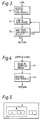
- Figure 1 is a data flow diagram of a compilation mechanism for generating a simulation model, including a compiler and a linker.
- Figure 2 is a flow chart showing the operation of the compiler when executing a "compile" option.
- Figure 3 is a flow chart showing the operation of the linker.
- Figure 4 is a flow chart showing the operation of the compiler when executing a "link" option.
- Figure 5 is a schematic diagram illustrating an example of operation of the compilation mechanism.
- the compilation mechanism includes a network compiler 10, and a linker 11.
- the compiler 10 makes use of a design database 12, a behaviour library 13 and a compiler steering file 14.
- the compiler 10 generates a partial model 15 which is then processed by the linker 11 to produce a compiled simulation model 16.
- the design database 12 consists of a collection of data objects, each having a unique name. These objects include a plurality of network objects, each of which defines a design unit in terms of a sub-network.
- the design database also holds any simulation models that have already been generated by the network compiler. In general, these models include a top-level simulation model of the system to be simulated, and may also include a number of sub-models for individual parts of the system. Each model has associated with it a list of sub-models (if any) that have been used in generating that model, as will be described in more detail later.
- the behaviour library 13 consists of a collection of compiled behaviour specifications, each of which specifies the behaviour of a design unit in terms of a set of rules or algorithms.
- the compiler steering file 14 comprises a set of statements of the form: (keyword, name) Where "name” is the name of a particular design unit, and "keyword” is one of the following options.
- a CHECK command 17 is also provided, for checking that during simulation the outputs of concurrently compiled behaviour and sub-network (or sub-model) are the same.
- this shows the operation of the compiler 10 in response to a COMPILE command, specifying that a simulation model is to be generated for a particular top-level design unit.
- a top-level design A comprises design units B and E.
- Unit B has been expanded as a sub-network consisting of design units C and D. It is also assumed that, in the course of developing the simulation model for A, sub-models have been compiled for units B and C.
- COMPILE option of the compiler 10 is first called to re-compile the sub-model for unit C.
- the COMPILE (LINK) option is then called to update the sub-model for unit B.
- COMPILE (LINK) option is called again to update the model for the top-level design A.
- the amount of re-compilation required in both cases is less than if the whole model had to be re-compiled. Moreover, the amount of re-compilation depends on the extent of the changes: smaller changes require less recompilation.
Landscapes
- Engineering & Computer Science (AREA)
- Theoretical Computer Science (AREA)
- Physics & Mathematics (AREA)
- General Engineering & Computer Science (AREA)
- Computer Hardware Design (AREA)
- General Physics & Mathematics (AREA)
- Evolutionary Computation (AREA)
- Geometry (AREA)
- Software Systems (AREA)
- Stored Programmes (AREA)
- Test And Diagnosis Of Digital Computers (AREA)
Description
- This invention relates to a compilation mechanism for generating a simulation model of a logic system.
- Simulation models are widely used as design aids in the design and development of complex logic systems, such as computer systems. Such simulation models are generally implemented by means of software, running on general-purpose computer hardware. However, in principle, they could alternatively be implemented using special purpose hardware techniques.
- The design of a logic system may be represented by a number of design units, connected together in a network in a specified manner. Each of these units may be represented by a behaviour specification, ie a set of rules or algorithms that specify the behaviour of the unit. Alternatively, a design unit may be represented by a sub-network of lower-level design units, each of which in turn may be represented either by a behaviour specification or a sub-network. In other words, the design can be specified as a hierarchical network. A compiler program can be used to generate a simulation model for the system from these design units.
- It has been found that for complex designs comprising several VLSI chips (each chip typically equivalent to 50-100 thousand gates), the compilation time can be excessively high (running into hours on a mainframe computer) due to the many levels of hierarchy and the complexity of the sub-networks. Another problem with this is that, if changes are made to any of the design units in the course of development of the design, the whole simulation model must be recompiled no matter how small the changes. This is extremely time consuming and severely restricts designer productivity.
- The object of the present invention is to overcome or alleviate this problem and also to speed up the compilation process for large simulation models as a whole.
- According to the invention as defined in claim 1 there is provided a computer system for generating a simulation model of a digital electronic system consisting of a plurality of design units, the computer system comprising:
- a) a design database storing a plurality of network objects each network object defining one of said design units in terms of a sub-network of further design units, the design database also storing a plurality of previously compiled sub-models for simulating respective design units,
- b) compilation means for using said network objects in the design database to expand a selected design unit as a sub-network of further design units, and for generating a list of compiled sub-models stored in said design database for simulating those further design units, and
- c) linking means for linking together the compiled sub-models on said list, to produce a compiled simulation model for said selected design unit.
-
- A corresponding method of generating a simulation model is defined in claim 4.
- This pre-compiled sub-model may be derived by a previous invocation of the same compilation mechanism on the sub-network. A simulation model hierarchy, similar to the network hierarchy, can therefore be constructed. This is the "compile" option of the compilation mechanism. Another option of the compilation mechanism, herein referred to as the "link" option, allows an existing simulation model to be updated following modification of a sub-model forming part of that model. The modified sub-network is first compiled using the compile option. The new sub-model is then linked into the simulation model in place of the existing sub-model.
- In a preferred embodiment of the invention, at least one of the design units may be expanded as both a sub-model and a behaviour arranged within the model such that they will execute in parallel during simulation.
- The concept of employing pre-compiled sub-models in the compilation alleviates the need to expand the sub-networks and therefore significantly reduces the compilation time. Experience has shown that large model builds using this system can be achieved in minutes rather than hours.
- It will be seen that the invention also allows incremental compilation of a simulation model, providing the ability to carry out design changes without a major recompilation overhead. This is of particular benefit when making minor changes to large designs, and it has been found that designer productivity can be substantially increased as a result.
- Figure 1 is a data flow diagram of a compilation mechanism for generating a simulation model, including a compiler and a linker.
- Figure 2 is a flow chart showing the operation of the compiler when executing a "compile" option.
- Figure 3 is a flow chart showing the operation of the linker.
- Figure 4 is a flow chart showing the operation of the compiler when executing a "link" option.
- Figure 5 is a schematic diagram illustrating an example of operation of the compilation mechanism.
- One compilation mechanism in accordance with the present invention will now be described by way of example with reference to the accompanying drawings.
- Referring to Figure 1, the compilation mechanism includes a
network compiler 10, and a linker 11. Thecompiler 10 makes use of adesign database 12, abehaviour library 13 and acompiler steering file 14. As will be described, thecompiler 10 generates apartial model 15 which is then processed by the linker 11 to produce a compiledsimulation model 16. - The
design database 12 consists of a collection of data objects, each having a unique name. These objects include a plurality of network objects, each of which defines a design unit in terms of a sub-network. The design database also holds any simulation models that have already been generated by the network compiler. In general, these models include a top-level simulation model of the system to be simulated, and may also include a number of sub-models for individual parts of the system. Each model has associated with it a list of sub-models (if any) that have been used in generating that model, as will be described in more detail later. - The
behaviour library 13 consists of a collection of compiled behaviour specifications, each of which specifies the behaviour of a design unit in terms of a set of rules or algorithms. - The
compiler steering file 14 comprises a set of statements of the form:
(keyword, name)
Where "name" is the name of a particular design unit, and "keyword" is one of the following options. - Behaviour - simulate the design unit by means of a behavioural simulation, ie in terms of its behaviour specification.
- Model - use a previously compiled sub-model to simulate the design unit.
- Network - expand the design unit in terms of a sub-network.
- Concurrent - simulate the design unit in terms of its behaviour specification and also expand the unit as a sub-network (or use a previously compiled sub-model if the unit is also specified as a model), in parallel with the behavioural simulation.
-
- A
CHECK command 17 is also provided, for checking that during simulation the outputs of concurrently compiled behaviour and sub-network (or sub-model) are the same. - Referring now to Figure 2, this shows the operation of the
compiler 10 in response to a COMPILE command, specifying that a simulation model is to be generated for a particular top-level design unit. - (21) The compiler first selects a design unit from the
database 12 for processing. Initially, this is the top-level design unit. - (22) The compiler then examines the
steering file 14 to find a statement relating to the selected design unit. The compiler branches according to the keyword in the statement. - (23) If the keyword is "Behaviour", the compiler fetches the
behaviour specification for the design unit from the
behaviour library 13 and records a reference to it in thepartial model 15. This specification contains the simulation code necessary for simulating the behaviour. - (24) If the keyword is "Model", the compiler finds a
previously compiled sub-model for the design unit from the
design database, and updates a list of sub-models in the
partial model 15 for subsequent linking. If no previously compiled sub-model can be found, an error message is returned. - (25) If the keyword is "Network", the compiler expands the
selected design unit, by replacing it with a sub-network,
obtained from the
design database 14. All the design units in the sub-network then become available for processing. - (26) If the keyword is "Concurrent", the compiler performs the actions specified above for "Behaviour", arranging the behaviour in parallel with an existing network or sub-model, so that the compiled simulation model will contain both the behavioural representation and a sub-network expansion (or compiled sub-model) of the design unit in parallel. If no statement can be found in the steering file for the design unit, the compiler looks for a behaviour first, a model second and a network last. If one of these is found, the compiler proceeds as described above. Otherwise an error message is returned.
- (27) If there are now no more design units for processing,
the compilation is complete. Otherwise, the compiler returns
to step 21 above, to select the next design unit for
processing.
Referring now to Figure 3, this shows the operation of the
linker 16. - (31) The link command accesses the list of compiled
sub-models (if any) associated with the
partial model 15. - (32) For each sub-model in the list, the linker fetches this
sub-model from the
design database 12 and links it in to thesimulation model 16, performing any necessary "fixing-up" of references. - (33) The above step is repeated for each sub-model in the
list in turn.
When the
simulation model 16 has been generated and linked, it can be run, using suitable input test data sequences. Where the simulation model contains concurrent representations of a design unit in terms of its behaviour and its network expansion (or sub-model), the results of these two representations can be compared, to check for equivalence, using the CHECK command 17.Referring now to Figure 4, this shows the operation of thecompiler 10 in response to a COMPILE (LINK) command. This option is used in order to update an existing simulation model, following modification of a sub-model forming part of that model. - (41) The model to be updated is read from the
design database 12 and is stored as thefull model 16. - (42) All sub-models within the
model 16 are discarded to produce thepartial model 15. Thepartial model 15 can then be processed by thelinker 11, as described above, to link in the latest versions of all the sub-models in its associated list of sub-models. -
- An example of the operation of the compiler mechanism will now be described with reference to Figure 5.
- In this example, it is assumed that a top-level design A comprises design units B and E. Unit B has been expanded as a sub-network consisting of design units C and D. It is also assumed that, in the course of developing the simulation model for A, sub-models have been compiled for units B and C.
- Suppose now a minor change is made to the simulation model, by making modifications to unit C. In this case, the COMPILE option of the
compiler 10 is first called to re-compile the sub-model for unit C. The COMPILE (LINK) option is then called to update the sub-model for unit B. Finally, the COMPILE (LINK) option is called again to update the model for the top-level design A. - Consider now the case where a more extensive change has been made to the simulation model, affecting both unit C and the way in which this unit interacts with unit B. In this case, the COMPILE option of the compiler is first called to re-compile the sub-model for unit C. The COMPILE option is then called again, to re-compile the sub-model for unit B. Finally, the COMPILE (LINK) option is called, to update the top-level design A.
- It can be seen from this example that the amount of re-compilation required in both cases is less than if the whole model had to be re-compiled. Moreover, the amount of re-compilation depends on the extent of the changes: smaller changes require less recompilation.
Claims (4)
- A computer system for generating a simulation model of a digital electronic system consisting of a plurality of design units, the computer system comprising:a) a design database storing a plurality of network objects, each network object defining one of said design units in terms of a sub-network of further design units, the design database also storing a plurality of previously compiled sub-models for simulating respective design units,b) compilation means for using said network objects in the design database to expand a selected design unit as a sub-network of further design units, and for generating a list of compiled sub-models stored in said design database for simulating those further design units, andc) linking means for linking together the compiled sub-models on said list, to produce a compiled simulation model for said selected design unit.
- A computer system according to Claim 1 further comprising means for updating an existing simulation model following a change to a sub-model that forms part of it, by linking a later version of a sub-model into the simulation model in place of an existing sub-model.
- A computer system according to Claim 1 or 2, further including a steering file comprising a set of statements, each specifying whether a design unit is to be expanded as a sub-network, represented in terms of its behaviour specification, simulated by a previously compiled sub-model, or concurrently compiled as behavioural specification arranged in parallel with said sub-model or sub-network.
- A method of generating a simulation model of a digital electronic system consisting of a plurality of design units, the method comprising the steps:a) creating a design database holding a plurality of network objects, each network object defining one of said design units in terms of a sub-network of further design units, the design database also holding a plurality of previously compiled sub-models for simulating respective design units,b) using said network objects in the design database to expand a selected design unit as a sub-network of further design units, and generating a list of compiled sub-models stored in said design database for simulating those further design units, andc) linking together the compiled sub-models on said list, to produce a compiled simulation model for said selected design unit.
Applications Claiming Priority (2)
| Application Number | Priority Date | Filing Date | Title |
|---|---|---|---|
| GB9224225 | 1992-11-19 | ||
| GB929224225A GB9224225D0 (en) | 1992-11-19 | 1992-11-19 | Compilation mechanism for a simulation model |
Publications (3)
| Publication Number | Publication Date |
|---|---|
| EP0598476A2 EP0598476A2 (en) | 1994-05-25 |
| EP0598476A3 EP0598476A3 (en) | 1995-02-15 |
| EP0598476B1 true EP0598476B1 (en) | 2000-07-12 |
Family
ID=10725327
Family Applications (1)
| Application Number | Title | Priority Date | Filing Date |
|---|---|---|---|
| EP93307288A Expired - Lifetime EP0598476B1 (en) | 1992-11-19 | 1993-09-15 | Compilation mechanism for a simulation model |
Country Status (4)
| Country | Link |
|---|---|
| EP (1) | EP0598476B1 (en) |
| JP (1) | JPH06231203A (en) |
| DE (1) | DE69329007T2 (en) |
| GB (1) | GB9224225D0 (en) |
Families Citing this family (5)
| Publication number | Priority date | Publication date | Assignee | Title |
|---|---|---|---|---|
| JP3192906B2 (en) * | 1994-03-11 | 2001-07-30 | 富士通株式会社 | Logic simulation system and logic change method |
| US5854903A (en) * | 1995-11-07 | 1998-12-29 | Lucent Technologies Inc. | Optimization method for routing and logical network design in multi-service networks |
| US6152612A (en) * | 1997-06-09 | 2000-11-28 | Synopsys, Inc. | System and method for system level and circuit level modeling and design simulation using C++ |
| CN102609574B (en) * | 2012-01-19 | 2013-11-13 | 武汉大学 | Virtual reality simulation platform system with overhead power transmission conductor galloping and galloping preventing designs |
| US10318702B2 (en) | 2016-01-19 | 2019-06-11 | Ford Motor Company | Multi-valued decision diagram reversible restriction |
-
1992
- 1992-11-19 GB GB929224225A patent/GB9224225D0/en active Pending
-
1993
- 1993-09-15 EP EP93307288A patent/EP0598476B1/en not_active Expired - Lifetime
- 1993-09-15 DE DE69329007T patent/DE69329007T2/en not_active Expired - Fee Related
- 1993-11-15 JP JP5284694A patent/JPH06231203A/en active Pending
Also Published As
| Publication number | Publication date |
|---|---|
| EP0598476A3 (en) | 1995-02-15 |
| DE69329007T2 (en) | 2001-05-17 |
| DE69329007D1 (en) | 2000-08-17 |
| GB9224225D0 (en) | 1993-01-06 |
| EP0598476A2 (en) | 1994-05-25 |
| JPH06231203A (en) | 1994-08-19 |
Similar Documents
| Publication | Publication Date | Title |
|---|---|---|
| US5983277A (en) | Work group computing for electronic design automation | |
| US5691925A (en) | Deriving tractable sub-system for model of larger system | |
| US5068812A (en) | Event-controlled LCC stimulation | |
| US7143373B2 (en) | Method and apparatus for evaluating and debugging assertions | |
| US5870590A (en) | Method and apparatus for generating an extended finite state machine architecture for a software specification | |
| US6606734B2 (en) | Simulation method and compiler for hardware/software programming | |
| JP4886838B2 (en) | Parallelization method, system, and program | |
| JPH08512152A (en) | Incremental generation system | |
| Bergmann et al. | A benchmark evaluation of incremental pattern matching in graph transformation | |
| US7194726B2 (en) | Method for automatically decomposing dynamic system models into submodels | |
| CN117034821B (en) | Regression verification method and medium for chip design front-end simulation verification | |
| Fauth et al. | Automated generation of DSP program development tools using a machine description formalism | |
| JP5479942B2 (en) | Parallelization method, system, and program | |
| US6438514B1 (en) | Generation of a system model | |
| CN111722597B (en) | Method and system for preparing engineering data for an industrial control system | |
| EP0598476A2 (en) | Compilation mechanism for a simulation model | |
| US5848262A (en) | Simulating digital systems by using vector processing | |
| US20060122820A1 (en) | Scripting language for domain-specific modification of a simulation model | |
| Hainque et al. | Cronos: a separate compilation tool set for modular esterel applications | |
| US7181704B1 (en) | Method and system for designing integrated circuits using implementation directives | |
| EP0592076B1 (en) | Compilation mechanism for a simulation model | |
| Herrmannsdörfer et al. | Library concepts for model reuse | |
| Infante et al. | Proving structured programs correct, level by level | |
| Ceri et al. | Software prototyping by relational techniques: experiences with program construction systems | |
| Oliveira et al. | A tactic language for refinement of state-rich concurrent specifications |
Legal Events
| Date | Code | Title | Description |
|---|---|---|---|
| PUAI | Public reference made under article 153(3) epc to a published international application that has entered the european phase |
Free format text: ORIGINAL CODE: 0009012 |
|
| AK | Designated contracting states |
Kind code of ref document: A2 Designated state(s): DE FR GB IT |
|
| PUAL | Search report despatched |
Free format text: ORIGINAL CODE: 0009013 |
|
| AK | Designated contracting states |
Kind code of ref document: A3 Designated state(s): DE FR GB IT |
|
| 17P | Request for examination filed |
Effective date: 19950721 |
|
| RIC1 | Information provided on ipc code assigned before grant |
Free format text: 6G 06F 9/45 A, 6G 06F 17/50 B |
|
| GRAG | Despatch of communication of intention to grant |
Free format text: ORIGINAL CODE: EPIDOS AGRA |
|
| GRAG | Despatch of communication of intention to grant |
Free format text: ORIGINAL CODE: EPIDOS AGRA |
|
| GRAH | Despatch of communication of intention to grant a patent |
Free format text: ORIGINAL CODE: EPIDOS IGRA |
|
| 17Q | First examination report despatched |
Effective date: 19991201 |
|
| GRAH | Despatch of communication of intention to grant a patent |
Free format text: ORIGINAL CODE: EPIDOS IGRA |
|
| GRAA | (expected) grant |
Free format text: ORIGINAL CODE: 0009210 |
|
| ITF | It: translation for a ep patent filed | ||
| AK | Designated contracting states |
Kind code of ref document: B1 Designated state(s): DE FR GB IT |
|
| REF | Corresponds to: |
Ref document number: 69329007 Country of ref document: DE Date of ref document: 20000817 |
|
| ET | Fr: translation filed | ||
| PLBE | No opposition filed within time limit |
Free format text: ORIGINAL CODE: 0009261 |
|
| STAA | Information on the status of an ep patent application or granted ep patent |
Free format text: STATUS: NO OPPOSITION FILED WITHIN TIME LIMIT |
|
| 26N | No opposition filed | ||
| REG | Reference to a national code |
Ref country code: GB Ref legal event code: IF02 |
|
| PGFP | Annual fee paid to national office [announced via postgrant information from national office to epo] |
Ref country code: FR Payment date: 20040812 Year of fee payment: 12 |
|
| PGFP | Annual fee paid to national office [announced via postgrant information from national office to epo] |
Ref country code: DE Payment date: 20040818 Year of fee payment: 12 |
|
| PG25 | Lapsed in a contracting state [announced via postgrant information from national office to epo] |
Ref country code: IT Free format text: LAPSE BECAUSE OF NON-PAYMENT OF DUE FEES;WARNING: LAPSES OF ITALIAN PATENTS WITH EFFECTIVE DATE BEFORE 2007 MAY HAVE OCCURRED AT ANY TIME BEFORE 2007. THE CORRECT EFFECTIVE DATE MAY BE DIFFERENT FROM THE ONE RECORDED. Effective date: 20050915 |
|
| PG25 | Lapsed in a contracting state [announced via postgrant information from national office to epo] |
Ref country code: DE Free format text: LAPSE BECAUSE OF NON-PAYMENT OF DUE FEES Effective date: 20060401 |
|
| PG25 | Lapsed in a contracting state [announced via postgrant information from national office to epo] |
Ref country code: FR Free format text: LAPSE BECAUSE OF NON-PAYMENT OF DUE FEES Effective date: 20060531 |
|
| REG | Reference to a national code |
Ref country code: FR Ref legal event code: ST Effective date: 20060531 |
|
| PGFP | Annual fee paid to national office [announced via postgrant information from national office to epo] |
Ref country code: GB Payment date: 20090922 Year of fee payment: 17 |
|
| GBPC | Gb: european patent ceased through non-payment of renewal fee |
Effective date: 20100915 |
|
| PG25 | Lapsed in a contracting state [announced via postgrant information from national office to epo] |
Ref country code: GB Free format text: LAPSE BECAUSE OF NON-PAYMENT OF DUE FEES Effective date: 20100915 |