EP0598290A1 - Automatic slack adjuster for the brake lever for an S-cam automotive drum brake - Google Patents
Automatic slack adjuster for the brake lever for an S-cam automotive drum brake Download PDFInfo
- Publication number
- EP0598290A1 EP0598290A1 EP93117952A EP93117952A EP0598290A1 EP 0598290 A1 EP0598290 A1 EP 0598290A1 EP 93117952 A EP93117952 A EP 93117952A EP 93117952 A EP93117952 A EP 93117952A EP 0598290 A1 EP0598290 A1 EP 0598290A1
- Authority
- EP
- European Patent Office
- Prior art keywords
- brake
- control
- wheel
- clutch
- screw
- Prior art date
- Legal status (The legal status is an assumption and is not a legal conclusion. Google has not performed a legal analysis and makes no representation as to the accuracy of the status listed.)
- Granted
Links
- 230000006835 compression Effects 0.000 claims abstract description 9
- 238000007906 compression Methods 0.000 claims abstract description 9
- 230000007423 decrease Effects 0.000 description 3
- 230000003247 decreasing effect Effects 0.000 description 3
- 230000002860 competitive effect Effects 0.000 description 1
Images


Classifications
-
- F—MECHANICAL ENGINEERING; LIGHTING; HEATING; WEAPONS; BLASTING
- F16—ENGINEERING ELEMENTS AND UNITS; GENERAL MEASURES FOR PRODUCING AND MAINTAINING EFFECTIVE FUNCTIONING OF MACHINES OR INSTALLATIONS; THERMAL INSULATION IN GENERAL
- F16D—COUPLINGS FOR TRANSMITTING ROTATION; CLUTCHES; BRAKES
- F16D65/00—Parts or details
- F16D65/38—Slack adjusters
- F16D65/40—Slack adjusters mechanical
- F16D65/52—Slack adjusters mechanical self-acting in one direction for adjusting excessive play
- F16D65/56—Slack adjusters mechanical self-acting in one direction for adjusting excessive play with screw-thread and nut
-
- F—MECHANICAL ENGINEERING; LIGHTING; HEATING; WEAPONS; BLASTING
- F16—ENGINEERING ELEMENTS AND UNITS; GENERAL MEASURES FOR PRODUCING AND MAINTAINING EFFECTIVE FUNCTIONING OF MACHINES OR INSTALLATIONS; THERMAL INSULATION IN GENERAL
- F16D—COUPLINGS FOR TRANSMITTING ROTATION; CLUTCHES; BRAKES
- F16D65/00—Parts or details
- F16D65/38—Slack adjusters
- F16D65/40—Slack adjusters mechanical
- F16D65/52—Slack adjusters mechanical self-acting in one direction for adjusting excessive play
- F16D65/60—Slack adjusters mechanical self-acting in one direction for adjusting excessive play for angular adjustment of two concentric parts of the brake control systems
-
- F—MECHANICAL ENGINEERING; LIGHTING; HEATING; WEAPONS; BLASTING
- F16—ENGINEERING ELEMENTS AND UNITS; GENERAL MEASURES FOR PRODUCING AND MAINTAINING EFFECTIVE FUNCTIONING OF MACHINES OR INSTALLATIONS; THERMAL INSULATION IN GENERAL
- F16D—COUPLINGS FOR TRANSMITTING ROTATION; CLUTCHES; BRAKES
- F16D2125/00—Components of actuators
- F16D2125/18—Mechanical mechanisms
- F16D2125/20—Mechanical mechanisms converting rotation to linear movement or vice versa
- F16D2125/22—Mechanical mechanisms converting rotation to linear movement or vice versa acting transversely to the axis of rotation
- F16D2125/28—Cams; Levers with cams
- F16D2125/30—Cams; Levers with cams acting on two or more cam followers, e.g. S-cams
Definitions
- This invention relates to a brake lever for attachment to a splined S-cam shaft of an automotive drum brake and connection to a brake cylinder push rod.
- the brake lever includes a worm wheel, rotatably mounted in a housing of the brake lever and having internal splines for cooperation with the S-cam shaft, a worm screw, rotatable in the housing perpendicularly to the worm wheel and meshing therewith, and a control arrangement for transmitting a control movement from a reference point to a clutch wheel, which is rotatable on the worm screw, depending on the angular movement of the brake lever, and which forms a clutch with the worm screw normally held engaged by a strong compression spring.
- This control arrangement includes a control disc, which is rotatable coaxially with the worm wheel and is connected to a control ring having a control arm for establishing the reference point by being attached to a fixed part of a vehicle chassis, a pinion meshing with the toothed periphery of the control disc, a carrier wheel and a control screw, the latter two parts being coaxial with the pinion and the last mentioned part being in tooth engagement with the clutch wheel, wherein the axis of the worm screw is perpendicular to the axis of the pinion, carrier wheel and control screw.
- S-cam drum brakes are often used. Brake shoes provided with brake linings may be pressed apart against a brake drum by means of a generally S-shaped cam rotatable with a shaft (called the S-cam shaft) extending out of the brake drum.
- a lever, called the brake lever, attached to the S-cam shaft is connected to a piston rod of a preferably pneumatic brake cylinder in the vehicle underframe.
- the adjusting mechanism is able to differentiate between the piston rod stroke depending on the wear of the brake linings and that depending on the often considerable elasticity in the different parts between the brake cylinder and the brake drum. This means that the automatic adjustment reduces the clearance to the normal and desired value when it has become excessive, due for example to wear of the brake linings, whereas the mechanism ignores the influence of the elasticity.
- an automatic brake lever is a safety device working under extremely hard conditions as regards loads and environment. Further, the available space for the brake lever is often very limited. The reliability must be high and the periods between normal services as long as possible. Last but not least the price must be competitive.
- the automatic brake lever shall thus preferably have a so called floating reference point or fixpoint.
- the control arrangement for the brake lever ending with the clutch wheel on the worm screw shall have certain properties.
- the mechanism shall be slow-acting, which means that only a fraction of the whole excessive slack is to be reduced at each brake application.
- the control arrangement must therefore have a certain reduction, which may be obtained by a gearing between the control ring with its control arm and the clutch ring, namely in this case - coaxial with each other - the pinion, the carrier wheel and the control screw engaging the clutch ring perpendicular thereto.
- a brake lever of the kind described above having all the cited advantages and desirable characteristics is according to the invention attained in that the carrier wheel can be turned or has a lost motion relative to the pinion corresponding to a desired slack or control distance for the brake lever and is angularly biassed by a torsion spring in a direction corresponding to brake application and in that a toothed one-way clutch is formed between the carrier wheel and the control screw.
- the torsion spring also acts as a compression spring for keeping the one-way clutch engaged.
- Fig 1 is a side view of a brake lever according to the invention
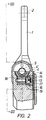
- Fig 2 is a view along the line II-II in Fig 1
- Fig 3 is a view along the line III-III in Fig 2
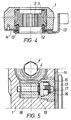
- Fig 4 is a view along the line IV-IV in Fig 1
- Fig 5 is a part view from Fig 2 to a larger scale.
- a brake lever of the general type concerned is well known in the art. It constitutes a connection lever in a brake system of a heavy road vehicle between a push rod of a brake cylinder and a splined S-cam shaft of a drum brake arrangement, comprising a brake drum and brake shoes to be pressed apart by an S-cam for braking engagement with the brake drum.
- a brake lever housing 1 is at its upper end provided with a hole 2 for connection to the brake cylinder push rod. Towards its opposite end the brake lever is provided with a rotatable worm wheel 3, which has internal splines 3' for attachment to the S-cam shaft. Meshing with this worm wheel 3 is a worm screw 4, which is rotatably mounted crosswise in the housing 1.
- the end of the worm screw 4 to the right in Fig 3 extends out of the housing 1, and the worm screw is here provided with a hexagonal tool grip 4' for manual rotation of the screw 4. At this end there is a cover 5 threaded into the housing 1 around the screw 4.
- a clutch wheel 6 is rotatable on the worm screw 4 and is journalled against the cover 5 by means of an axial bearing 7. Coacting, generally radial, toothed surfaces on the worm screw 4 and the clutch wheel 6 form a clutch 8.
- the worm screw 4 is biassed to the right in Fig 3 - or in other words for engagement of the clutch 8 - by a strong compression spring 9 arranged between a spring washer 10 at the end of the worm screw 4 and a spring cover 11 threaded into the housing 1.
- a control unit 12 - 14 is arranged in the same bore in the housing 1 as the worm wheel 3, but is not connected thereto. It has a rotatable control disc 12, which has a toothed periphery and is connected to an external control ring 13 having a control arm 13' extending therefrom. A plane cover 14 is arranged between the control disc 12 and the control ring 13 and is screwed to the housing 1 for rotatable attachement of the control unit 12 - 14.
- the control arm 13' is to be connected to a fixed part of the chassis of the vehicle on which the lever is rockably mounted.
- the purpose of the control unit 12 - 14 is to provide a reference or control signal for the brake lever, as will be explained below.
- pinion 15 Meshing with the toothed control disc 12 is a pinion 15, which is rotatable in the housing 1.
- This pinion 15 can be seen in Figs 1 and 2 but best in Fig 5, to which further reference is made.
- a carrier wheel 16 is arranged inside the pinion 15. It may be turned back and forth relative to the pinion only to a limited extent, corresponding to the desired slack between the brake shoes and the brake drum.
- the control distance or so called A-distance for the brake lever is accordingly defined between the pinion 15 and carrier wheel 16.
- These two parts are connected by means of a relatively weak torsion spring or return spring 17, which also has the function to keep a one-way clutch 19 (see below) engaged.
- a rotatable control screw 18 meshing with the clutch wheel 6 (Fig 3).
- the carrier wheel 16 and the control screw 18 are connected by means of a toothed one-way clutch 19.
- a brake lever of the kind concerned is to transmit the brake force from the brake cylinder to the S-cam shaft of the brake but also - with the help of the described device in the brake lever - to adjust the slack between the brake drum and the brake shoes to a desired value.
- the function of the brake lever with the built-in slack adjuster according to the invention will now be described.
- the slack is supposed to be excessive.
- the starting point for this description is that during a preceding brake operation the torsion spring 17 is tensioned in the rotational direction due to the play between the pinion 15 and the carrier wheel 16, corresponding to the desired slack between the brake drum and the brake shoes.
- the torque of the spring 17 is not great enough to drive the carrier wheel 16, control screw 18, clutch wheel 6, worm screw 4 and worm wheel 3, when the clutch 8 is engaged. This is the case when the housing 1 moves rotationally about the worm wheel axis in the counter-clockwise direction in Fig 1 an arc which corresponds to the application movement of the brake shoes before they have engaged the brake drum.
- the rotational resistance for the clutch wheel 6 is hereby greatly decreased, so that it can rotate without driving the worm screw 4 at the continued brake application.
Abstract
Description
- This invention relates to a brake lever for attachment to a splined S-cam shaft of an automotive drum brake and connection to a brake cylinder push rod.
- The brake lever includes a worm wheel, rotatably mounted in a housing of the brake lever and having internal splines for cooperation with the S-cam shaft, a worm screw, rotatable in the housing perpendicularly to the worm wheel and meshing therewith, and a control arrangement for transmitting a control movement from a reference point to a clutch wheel, which is rotatable on the worm screw, depending on the angular movement of the brake lever, and which forms a clutch with the worm screw normally held engaged by a strong compression spring.
- This control arrangement includes a control disc, which is rotatable coaxially with the worm wheel and is connected to a control ring having a control arm for establishing the reference point by being attached to a fixed part of a vehicle chassis, a pinion meshing with the toothed periphery of the control disc, a carrier wheel and a control screw, the latter two parts being coaxial with the pinion and the last mentioned part being in tooth engagement with the clutch wheel, wherein the axis of the worm screw is perpendicular to the axis of the pinion, carrier wheel and control screw.
- Especially for heavy road vehicles, such as trucks and buses, so called S-cam drum brakes are often used. Brake shoes provided with brake linings may be pressed apart against a brake drum by means of a generally S-shaped cam rotatable with a shaft (called the S-cam shaft) extending out of the brake drum. A lever, called the brake lever, attached to the S-cam shaft is connected to a piston rod of a preferably pneumatic brake cylinder in the vehicle underframe. Thus, at the admission of air under pressure to the brake cylinder a brake force will be transmitted from the piston rod via the brake lever to the S-cam shaft and the S-cam, which will press apart the brake shoes and thus apply the brakes.
- When wear of the brake linings occurs, a longer stroke of the brake cylinder piston rod will be necessary before the brake is applied. It has become common to provide the brake lever with internal means for automatically turning a worm screw in engagement with a worm wheel, which is attached to the S-cam shaft, and thus adjusting the angular position of the brake lever in dependence on the brake lining wear; a so equipped lever is in the art called an automatic brake lever.
- Most of the designs for such automatic brake levers are based on the so called piston stroke principle, i.e. the adjustment depends entirely on the piston rod stroke or in other words the angular movement of the brake lever past a certain value corresponding to the normal clearance or slack between the brake linings and the brake drum in the rest position.
- More recently it has been found that different reasons speak for a more advanced principle - the so called clearance sensing principle. In this case the adjusting mechanism is able to differentiate between the piston rod stroke depending on the wear of the brake linings and that depending on the often considerable elasticity in the different parts between the brake cylinder and the brake drum. This means that the automatic adjustment reduces the clearance to the normal and desired value when it has become excessive, due for example to wear of the brake linings, whereas the mechanism ignores the influence of the elasticity.
- Different requirements are imposed on a product of this kind. Generally speaking an automatic brake lever is a safety device working under extremely hard conditions as regards loads and environment. Further, the available space for the brake lever is often very limited. The reliability must be high and the periods between normal services as long as possible. Last but not least the price must be competitive.
- Still further it is desirable to obviate the necessity for mounting the brake lever in a certain predetermined position, which is inconvenient not only at the initial mounting but even more after later servicing. The automatic brake lever shall thus preferably have a so called floating reference point or fixpoint.
- The control arrangement for the brake lever ending with the clutch wheel on the worm screw shall have certain properties. Preferably the mechanism shall be slow-acting, which means that only a fraction of the whole excessive slack is to be reduced at each brake application. The control arrangement must therefore have a certain reduction, which may be obtained by a gearing between the control ring with its control arm and the clutch ring, namely in this case - coaxial with each other - the pinion, the carrier wheel and the control screw engaging the clutch ring perpendicular thereto.
- Certain automatic brake levers with such a supplementary gearing are earlier known, such as US-A-3 526 303, US-A-4 484 665 and EP-A-30 766, which is regarded as the closest prior art.
- A problem with a conventional brake lever of the kind where the necessary reference point for the slack adjusting function of the lever is found in a fix point in the vehicle chassis, is that the original mounting of the lever has to be done with certain accuracy in order to obtain the later proper function.
- It is instead desirable to find a solution where the position of the reference point - and accordingly the angular position of the control arm relative to the lever housing - is immaterial for the proper function. The desirable condition can be called a floating reference point.
- It is also desirable - in a slow-acting, clearance-sensing adjuster with a floating reference point - to have the adjustment performed during the return stroke, when the different parts are less strained than during the brake application stroke.
- A brake lever of the kind described above having all the cited advantages and desirable characteristics is according to the invention attained in that the carrier wheel can be turned or has a lost motion relative to the pinion corresponding to a desired slack or control distance for the brake lever and is angularly biassed by a torsion spring in a direction corresponding to brake application and in that a toothed one-way clutch is formed between the carrier wheel and the control screw.
- The torsion spring also acts as a compression spring for keeping the one-way clutch engaged.
- The invention will be described in further detail below, reference being made to the accompanying drawings, in which Fig 1 is a side view of a brake lever according to the invention, Fig 2 is a view along the line II-II in Fig 1, Fig 3 is a view along the line III-III in Fig 2, Fig 4 is a view along the line IV-IV in Fig 1 and Fig 5 is a part view from Fig 2 to a larger scale.
- A brake lever of the general type concerned is well known in the art. It constitutes a connection lever in a brake system of a heavy road vehicle between a push rod of a brake cylinder and a splined S-cam shaft of a drum brake arrangement, comprising a brake drum and brake shoes to be pressed apart by an S-cam for braking engagement with the brake drum.
- A
brake lever housing 1 is at its upper end provided with ahole 2 for connection to the brake cylinder push rod. Towards its opposite end the brake lever is provided with arotatable worm wheel 3, which has internal splines 3' for attachment to the S-cam shaft. Meshing with thisworm wheel 3 is aworm screw 4, which is rotatably mounted crosswise in thehousing 1. - The end of the
worm screw 4 to the right in Fig 3 extends out of thehousing 1, and the worm screw is here provided with a hexagonal tool grip 4' for manual rotation of thescrew 4. At this end there is acover 5 threaded into thehousing 1 around thescrew 4. A clutch wheel 6 is rotatable on theworm screw 4 and is journalled against thecover 5 by means of an axial bearing 7. Coacting, generally radial, toothed surfaces on theworm screw 4 and the clutch wheel 6 form a clutch 8. - The
worm screw 4 is biassed to the right in Fig 3 - or in other words for engagement of the clutch 8 - by a strong compression spring 9 arranged between a spring washer 10 at the end of theworm screw 4 and aspring cover 11 threaded into thehousing 1. - A control unit 12 - 14 is arranged in the same bore in the
housing 1 as theworm wheel 3, but is not connected thereto. It has arotatable control disc 12, which has a toothed periphery and is connected to anexternal control ring 13 having a control arm 13' extending therefrom. Aplane cover 14 is arranged between thecontrol disc 12 and thecontrol ring 13 and is screwed to thehousing 1 for rotatable attachement of the control unit 12 - 14. - The control arm 13' is to be connected to a fixed part of the chassis of the vehicle on which the lever is rockably mounted. The purpose of the control unit 12 - 14 is to provide a reference or control signal for the brake lever, as will be explained below.
- Meshing with the
toothed control disc 12 is apinion 15, which is rotatable in thehousing 1. Thispinion 15 can be seen in Figs 1 and 2 but best in Fig 5, to which further reference is made. - A
carrier wheel 16 is arranged inside thepinion 15. It may be turned back and forth relative to the pinion only to a limited extent, corresponding to the desired slack between the brake shoes and the brake drum. The control distance or so called A-distance for the brake lever is accordingly defined between thepinion 15 andcarrier wheel 16. These two parts are connected by means of a relatively weak torsion spring or returnspring 17, which also has the function to keep a one-way clutch 19 (see below) engaged. - Coaxial with the
pinion 15 and thecarrier wheel 16 is arotatable control screw 18 meshing with the clutch wheel 6 (Fig 3). Thecarrier wheel 16 and thecontrol screw 18 are connected by means of a toothed one-way clutch 19. - The purpose of a brake lever of the kind concerned is to transmit the brake force from the brake cylinder to the S-cam shaft of the brake but also - with the help of the described device in the brake lever - to adjust the slack between the brake drum and the brake shoes to a desired value.
- The function of the brake lever with the built-in slack adjuster according to the invention will now be described. The slack is supposed to be excessive.
- The starting point for this description is that during a preceding brake operation the
torsion spring 17 is tensioned in the rotational direction due to the play between thepinion 15 and thecarrier wheel 16, corresponding to the desired slack between the brake drum and the brake shoes. The torque of thespring 17 is not great enough to drive thecarrier wheel 16,control screw 18, clutch wheel 6,worm screw 4 andworm wheel 3, when the clutch 8 is engaged. This is the case when thehousing 1 moves rotationally about the worm wheel axis in the counter-clockwise direction in Fig 1 an arc which corresponds to the application movement of the brake shoes before they have engaged the brake drum. - At the very first part of the brake application movement the
pinion 15 rolls on the control disc 12 a rotational distance corresponding to the play between thepinion 15 and thecarrier wheel 16. - At this movement the torque of the
torsion spring 17 decreases. - When this rotational distance has been passed, which means that the actual slack between the brake shoes and the brake drum is greater than desired, the
pinion 15 will start to carry thecarrier wheel 16 with it, so that the one-way clutch 19 gets a new engagement. - In the next stage the brake shoes engages the brake drum, so that the counterforce increases and the
worm screw 4 moves axially under compression of the compression spring 9, which means that the clutch 8 is disengaged. - The rotational resistance for the clutch wheel 6 is hereby greatly decreased, so that it can rotate without driving the
worm screw 4 at the continued brake application. - During the first part of the brake release the
pinion 15 rolls on the control disc 12 (in the direction opposite to that during brake application) and drives thecarrier wheel 16,control screw 18 and clutch wheel 6 via thetorsion spring 13. As the clutch 8 still is disengaged, theworm screw 4 is not driven. - When the brake shoes are about to leave their engagement with the brake drum and accordingly the force decreases, the compression spring 9 moves the
worm screw 4 to the right, again engaging the clutch 8. Hereby the rotational resistance for the clutch wheel 6 increases to the extent that its rotation is stopped. - At the continued release movement of the housing 1 (in the clockwise direction in Fig 1) the
pinion 15 rolls on thecontrol disc 12, but thetorsion spring 17 cannot turn thecarrier wheel 16 and thecontrol screw 18 due to the rotational resistance of the clutch wheel 6. This means that the play between thecarrier wheel 16 and thepinion 15 is consumed or in other words that the initial position between these two parts is reinstated, and that thetorsion spring 17 is tensioned. - During the remaining and last part of the release stroke of the brake lever the
pinion 15 rolls on thecontrol disc 12 and drives thecarrier wheel 16,control screw 18, clutch wheel 6,worm screw 4 andworm wheel 3, arranged on the S-cam, which is turned, so that the distance or slack between the brake shoes and the brake drum is decreased. As the decrease at each brake application is relatively minor, several applications may be needed, before the slack has been decreased to the desired value. - The above description of the function presupposes that the slack is excessive. If that is not the case, the brake application is virtually the same with the important difference that the one-way clutch 19 is not disengaged and reengaged in a new position. The description above of the release stroke is also valid with the exception that the movement stops when the play between the
pinion 15 and thecarrier wheel 16 has been consumed. Accordingly no adjustment occurs.
Claims (2)
- A brake lever for attachment to a splined S-cam shaft of an automotive drum brake and connection to a brake cylinder push rod, including
a worm wheel (3), rotatably mounted in a housing (1) of the brake lever and having internal splines (3') for cooperation with the S-cam shaft, and a worm screw (4), rotatable in the housing perpendicularly to the worm wheel and meshing therewith, and
a control arrangement (13, 12, 15, 16, 18) for transmitting a control movement from a reference point (13') to a clutch wheel (6), which is rotatable on the worm screw (4), depending on the angular movement of the brake lever, and which forms a clutch (8) with the worm screw (4) normally held engaged by a strong compression spring (9),
the control arrangement including a control disc (12), which is rotatable coaxially with the worm wheel (3) and is connected to a control ring (13) having a control arm (13') for establishing the reference point by being attached to a fixed part of a vehicle chassis, a pinion (15) meshing with the toothed periphery of the control disc (12), a carrier wheel (16) and a control screw (18), the latter two parts being coaxial with the pinion and the last mentioned part being in tooth engagement with the clutch wheel (6), wherein the axis of the worm screw (4) is perpendicular to the axis of the pinion (15), carrier wheel (16) and control screw (18),
characterized in that the carrier wheel (16) can be turned or has a lost motion relative to the pinion (15) corresponding to a desired slack or control distance for the brake lever and is angularly biassed by a torsion spring (17) in a direction corresponding to brake application and in that a toothed one-way clutch (19) is formed between the carrier wheel (16) and the control screw (18). - A brake lever according to claim 1,
characterized in the the torsion spring (17) also acts as a compression spring for keeping the one-way clutch (19) engaged.
Applications Claiming Priority (2)
| Application Number | Priority Date | Filing Date | Title |
|---|---|---|---|
| SE9203455 | 1992-11-18 | ||
| SE9203455A SE470526B (en) | 1992-11-18 | 1992-11-18 | Brake lever for an S-cam brake on a road vehicle |
Publications (2)
| Publication Number | Publication Date |
|---|---|
| EP0598290A1 true EP0598290A1 (en) | 1994-05-25 |
| EP0598290B1 EP0598290B1 (en) | 1996-02-28 |
Family
ID=20387849
Family Applications (1)
| Application Number | Title | Priority Date | Filing Date |
|---|---|---|---|
| EP93117952A Expired - Lifetime EP0598290B1 (en) | 1992-11-18 | 1993-11-05 | Automatic slack adjuster for the brake lever for an S-cam automotive drum brake |
Country Status (16)
| Country | Link |
|---|---|
| US (1) | US5327999A (en) |
| EP (1) | EP0598290B1 (en) |
| JP (1) | JP3642800B2 (en) |
| KR (2) | KR100287488B1 (en) |
| CN (1) | CN1034295C (en) |
| AT (1) | ATE134749T1 (en) |
| AU (1) | AU662254B2 (en) |
| BR (1) | BR9304764A (en) |
| CA (1) | CA2103080C (en) |
| CZ (1) | CZ284438B6 (en) |
| DE (1) | DE69301652T2 (en) |
| ES (1) | ES2085094T3 (en) |
| HU (1) | HU213339B (en) |
| MX (1) | MX9307183A (en) |
| RU (1) | RU2095657C1 (en) |
| SE (1) | SE470526B (en) |
Cited By (10)
| Publication number | Priority date | Publication date | Assignee | Title |
|---|---|---|---|---|
| WO1999050567A1 (en) * | 1998-03-27 | 1999-10-07 | Haldex Brake Products Ab | A control arrangement for a brake lever |
| WO2003083322A1 (en) * | 2002-04-01 | 2003-10-09 | Madras Engineering Industries Limited | An automatic brake adjuster for adjusting the slack between the brake lining and brake drum of a vehicular braking system |
| WO2006122672A1 (en) * | 2005-05-20 | 2006-11-23 | Knorr-Bremse Systeme für Nutzfahrzeuge GmbH | Linkage positioner for a drum brake |
| WO2007023508A1 (en) * | 2005-08-25 | 2007-03-01 | Madras Engineering Industries Private Ltd. | An automatic brake adjuster for adjusting the slack between the brake lining and brake drum of a vehicular braking system |
| WO2010016812A1 (en) | 2008-08-05 | 2010-02-11 | Aydinsan Firen Circirlari Ve Otomotiv Yedek Parçalari Imalati Pazarlama Ve Satisi Sanayi Ve Ticaret Limited Sirketi | Automatic slack adjuster for a brake lever |
| WO2011016047A1 (en) * | 2009-08-03 | 2011-02-10 | Madras Engineering Industries Private Limited | An automatic brake adjuster for adjusting the slack between the brake lining and brake drum of a vehicular braking system |
| CN102465987A (en) * | 2010-11-08 | 2012-05-23 | 戎华庆 | Novel automatic adjusting arm device for automobile brake |
| US9097305B2 (en) | 2010-08-20 | 2015-08-04 | Haldex Brake Products Ab | Brake lever for a brake for a vehicle |
| US9360070B2 (en) | 2011-10-14 | 2016-06-07 | Haldex Brake Products Ab | Brake lever for drum brake |
| WO2020231891A1 (en) * | 2019-05-15 | 2020-11-19 | Bendix Spicer Foundation Brake Llc | Automatic slack adjuster |
Families Citing this family (30)
| Publication number | Priority date | Publication date | Assignee | Title |
|---|---|---|---|---|
| SE469858B (en) * | 1992-02-05 | 1993-09-27 | Haldex Ab | Steering arm arrangement for a brake lever |
| US20060163014A1 (en) * | 2005-01-27 | 2006-07-27 | Crewson Gary E | Automatic slack adjuster with spring release spindle |
| CN100564926C (en) * | 2005-05-20 | 2009-12-02 | 克诺尔商用车制动系统有限公司 | The weight-lever regulator that is used for drum brake |
| US20070012529A1 (en) * | 2005-07-18 | 2007-01-18 | Kreidler Kevin L | Automatic slack adjuster |
| US7708122B2 (en) * | 2005-08-23 | 2010-05-04 | Bendix Commercial Vehicle Systems Llc | Automatic slack adjuster |
| US8042245B2 (en) * | 2007-01-05 | 2011-10-25 | Terry Olson | Repair kit for vehicular brake slack adjuster |
| US8672101B2 (en) * | 2008-11-18 | 2014-03-18 | Bendix Spicer Foundation Brake Llc | Automatic slack adjuster with clutch release cam |
| US8302742B2 (en) * | 2008-11-18 | 2012-11-06 | Bendix Spicer Foundation Brake Llc | Self-setting automatic slack adjuster with increased durability |
| US8453805B2 (en) * | 2008-12-12 | 2013-06-04 | Bendix Spicer Foundation Brake Llc | Automatic slack adjuster with ball detent clutch |
| CN101526116B (en) * | 2009-03-24 | 2012-03-07 | 隆中控股集团有限公司 | Automatic adjusting arm of automobile |
| TR200907444A2 (en) | 2009-10-01 | 2010-03-22 | Büyük Eker Bi̇jon Sanayi̇ Ve Ti̇caret Anoni̇m Şi̇rketi̇ | Drive angle adjustment device |
| RU2519587C2 (en) * | 2011-02-28 | 2014-06-20 | Андрей Андреевич Боталенко | Automotive brake regulator |
| RU2537063C2 (en) * | 2013-02-27 | 2014-12-27 | Боталенко Андрей Андреевич | Vehicle brake controller |
| EP3093518B2 (en) | 2015-05-11 | 2022-01-12 | ZF CV Systems Europe BV | Readjustment unit for an automatic rod positioner |
| USD770343S1 (en) * | 2015-06-16 | 2016-11-01 | Haldex Brake Products Ab | Brake adjuster |
| USD770345S1 (en) * | 2015-06-16 | 2016-11-01 | Haldex Brake Products Ab | Brake adjuster |
| USD770346S1 (en) * | 2015-06-16 | 2016-11-01 | Haldex Brake Products Ab | Brake adjuster |
| USD770344S1 (en) * | 2015-06-16 | 2016-11-01 | Haldex Brake Products Ab | Brake adjuster |
| USD828250S1 (en) * | 2015-08-31 | 2018-09-11 | Cummins Inc. | Compression relief brake system |
| USD836505S1 (en) * | 2015-08-31 | 2018-12-25 | Cummins Inc. | Compression relief brake assembly |
| RU178189U1 (en) * | 2017-03-20 | 2018-03-26 | Общество с ограниченной ответственностью "Ар Си Эр" | AUTOMATIC BRAKE LEVER |
| RU178420U1 (en) * | 2017-04-10 | 2018-04-03 | Общество с ограниченной ответственностью "Ар Си Эр" | AUTOMATIC ADJUSTING LEVER |
| USD860891S1 (en) * | 2017-06-10 | 2019-09-24 | Wabco India Limited | Slack adjuster |
| USD852696S1 (en) * | 2017-06-10 | 2019-07-02 | Wabco India Limited | Slack adjuster |
| USD860890S1 (en) * | 2017-06-10 | 2019-09-24 | Wabco India Limited | Slack adjuster |
| US10704630B2 (en) * | 2018-05-14 | 2020-07-07 | Bendix Spicer Foundation Brake Llc | Automatic slack adjuster with adjusting clutch in control train |
| DE102019005094B3 (en) * | 2019-07-23 | 2020-09-03 | Haldex Brake Products Ab | Adjustment unit for a brake and manufacturing process therefor |
| DE102019005788A1 (en) * | 2019-08-20 | 2021-02-25 | Haldex Brake Products Ab | Control arm assembly for a brake lever |
| US11655869B2 (en) | 2020-07-10 | 2023-05-23 | Haldex Brake Products Corporation | Brake adjuster with brake stroke indicator |
| DE202020004103U1 (en) | 2020-09-29 | 2020-10-13 | Haldex Brake Products Ab | Brake lever for a brake of a motor vehicle |
Citations (9)
| Publication number | Priority date | Publication date | Assignee | Title |
|---|---|---|---|---|
| US3526303A (en) * | 1969-02-12 | 1970-09-01 | Autoset Corp | Automatic brake slack adjuster |
| EP0030766A1 (en) * | 1979-12-13 | 1981-06-24 | SAB Automotive AB | A brake lever for an S-cam automotive drum brake |
| US4484665A (en) * | 1980-11-26 | 1984-11-27 | Svensson Sten Eric | Brake adjuster |
| EP0154799A2 (en) * | 1984-03-15 | 1985-09-18 | Bergische Achsenfabrik Fr. Kotz & Söhne | Adjusting device for vehicle brakes |
| EP0158034A1 (en) * | 1984-03-15 | 1985-10-16 | Bergische Achsenfabrik Fr. Kotz & Söhne | Vehicle brakes slack adjuster |
| EP0216008A2 (en) * | 1985-09-21 | 1987-04-01 | WABCO Westinghouse Fahrzeugbremsen GmbH | Automatic adjusting device for the brake lever of a brake, particularly for road vehicles |
| US4875557A (en) * | 1987-12-19 | 1989-10-24 | Man Nutzfahrzeuge Gmbh | Brake play resetting device |
| EP0319693B1 (en) * | 1987-12-08 | 1991-11-13 | Bergische Achsenfabrik Fr. Kotz & Söhne | Adjusting device for vehicle brakes |
| EP0460372A2 (en) * | 1990-06-05 | 1991-12-11 | WABCO GmbH | Device for automatically adjusting a brake, especially vehicle brake |
Family Cites Families (1)
| Publication number | Priority date | Publication date | Assignee | Title |
|---|---|---|---|---|
| DE2443004C2 (en) * | 1974-09-07 | 1983-03-31 | M.A.N. Maschinenfabrik Augsburg-Nürnberg AG, 8000 München | Adjustment device for brakes |
-
1992
- 1992-11-18 SE SE9203455A patent/SE470526B/en not_active IP Right Cessation
-
1993
- 1993-10-22 HU HU9302992A patent/HU213339B/en not_active IP Right Cessation
- 1993-11-05 EP EP93117952A patent/EP0598290B1/en not_active Expired - Lifetime
- 1993-11-05 ES ES93117952T patent/ES2085094T3/en not_active Expired - Lifetime
- 1993-11-05 AT AT93117952T patent/ATE134749T1/en not_active IP Right Cessation
- 1993-11-05 DE DE69301652T patent/DE69301652T2/en not_active Expired - Lifetime
- 1993-11-09 CN CN93114454A patent/CN1034295C/en not_active Expired - Lifetime
- 1993-11-15 AU AU50672/93A patent/AU662254B2/en not_active Ceased
- 1993-11-15 CA CA002103080A patent/CA2103080C/en not_active Expired - Fee Related
- 1993-11-17 MX MX9307183A patent/MX9307183A/en unknown
- 1993-11-17 KR KR1019980059856A patent/KR100287488B1/en active
- 1993-11-17 RU RU9393051356A patent/RU2095657C1/en not_active IP Right Cessation
- 1993-11-17 KR KR1019930024425A patent/KR940011265A/en not_active IP Right Cessation
- 1993-11-17 JP JP32305593A patent/JP3642800B2/en not_active Expired - Lifetime
- 1993-11-17 US US08/153,918 patent/US5327999A/en not_active Expired - Lifetime
- 1993-11-17 CZ CZ932459A patent/CZ284438B6/en not_active IP Right Cessation
- 1993-11-18 BR BR9304764A patent/BR9304764A/en not_active IP Right Cessation
Patent Citations (9)
| Publication number | Priority date | Publication date | Assignee | Title |
|---|---|---|---|---|
| US3526303A (en) * | 1969-02-12 | 1970-09-01 | Autoset Corp | Automatic brake slack adjuster |
| EP0030766A1 (en) * | 1979-12-13 | 1981-06-24 | SAB Automotive AB | A brake lever for an S-cam automotive drum brake |
| US4484665A (en) * | 1980-11-26 | 1984-11-27 | Svensson Sten Eric | Brake adjuster |
| EP0154799A2 (en) * | 1984-03-15 | 1985-09-18 | Bergische Achsenfabrik Fr. Kotz & Söhne | Adjusting device for vehicle brakes |
| EP0158034A1 (en) * | 1984-03-15 | 1985-10-16 | Bergische Achsenfabrik Fr. Kotz & Söhne | Vehicle brakes slack adjuster |
| EP0216008A2 (en) * | 1985-09-21 | 1987-04-01 | WABCO Westinghouse Fahrzeugbremsen GmbH | Automatic adjusting device for the brake lever of a brake, particularly for road vehicles |
| EP0319693B1 (en) * | 1987-12-08 | 1991-11-13 | Bergische Achsenfabrik Fr. Kotz & Söhne | Adjusting device for vehicle brakes |
| US4875557A (en) * | 1987-12-19 | 1989-10-24 | Man Nutzfahrzeuge Gmbh | Brake play resetting device |
| EP0460372A2 (en) * | 1990-06-05 | 1991-12-11 | WABCO GmbH | Device for automatically adjusting a brake, especially vehicle brake |
Cited By (17)
| Publication number | Priority date | Publication date | Assignee | Title |
|---|---|---|---|---|
| US6408993B1 (en) * | 1998-03-27 | 2002-06-25 | Haldex Brake Products Ab | Control arrangement for a brake lever |
| WO1999050567A1 (en) * | 1998-03-27 | 1999-10-07 | Haldex Brake Products Ab | A control arrangement for a brake lever |
| WO2003083322A1 (en) * | 2002-04-01 | 2003-10-09 | Madras Engineering Industries Limited | An automatic brake adjuster for adjusting the slack between the brake lining and brake drum of a vehicular braking system |
| US7789205B2 (en) | 2005-05-20 | 2010-09-07 | Knorr-Bremse Systeme Fuer Nutzfahrzeuge Gmbh | Linkage positioner for a drum brake |
| WO2006122672A1 (en) * | 2005-05-20 | 2006-11-23 | Knorr-Bremse Systeme für Nutzfahrzeuge GmbH | Linkage positioner for a drum brake |
| KR101121125B1 (en) * | 2005-08-25 | 2012-03-19 | 마드라스 엔지니어링 인더스트리스 프라이빗 리미티드 | An automatic brake adjuster for adjusting the slack between the brake lining and brake drum of a vehicular braking system |
| WO2007023508A1 (en) * | 2005-08-25 | 2007-03-01 | Madras Engineering Industries Private Ltd. | An automatic brake adjuster for adjusting the slack between the brake lining and brake drum of a vehicular braking system |
| US8245820B2 (en) | 2005-08-25 | 2012-08-21 | Madras Engineering Industries Private Limited | Automatic brake adjuster for adjusting the slack between the brake lining and brake drum of a vehicular braking system |
| WO2010016812A1 (en) | 2008-08-05 | 2010-02-11 | Aydinsan Firen Circirlari Ve Otomotiv Yedek Parçalari Imalati Pazarlama Ve Satisi Sanayi Ve Ticaret Limited Sirketi | Automatic slack adjuster for a brake lever |
| WO2011016047A1 (en) * | 2009-08-03 | 2011-02-10 | Madras Engineering Industries Private Limited | An automatic brake adjuster for adjusting the slack between the brake lining and brake drum of a vehicular braking system |
| RU2495292C1 (en) * | 2009-08-03 | 2013-10-10 | Мадрас Энджиниринг Индастриз Прайвит Лимитед | Automatic brake regulator to adjust gap between brake shoe and brake drum of automotive brake system |
| US9097305B2 (en) | 2010-08-20 | 2015-08-04 | Haldex Brake Products Ab | Brake lever for a brake for a vehicle |
| CN102465987A (en) * | 2010-11-08 | 2012-05-23 | 戎华庆 | Novel automatic adjusting arm device for automobile brake |
| CN102465987B (en) * | 2010-11-08 | 2015-12-02 | 戎华庆 | A kind of Novel automatic adjusting arm device for automobile brake |
| US9360070B2 (en) | 2011-10-14 | 2016-06-07 | Haldex Brake Products Ab | Brake lever for drum brake |
| WO2020231891A1 (en) * | 2019-05-15 | 2020-11-19 | Bendix Spicer Foundation Brake Llc | Automatic slack adjuster |
| US11209062B2 (en) | 2019-05-15 | 2021-12-28 | Bendix Commercial Vehicle Systems Llc | Automatic slack adjuster |
Also Published As
| Publication number | Publication date |
|---|---|
| HUT65966A (en) | 1994-08-29 |
| CN1034295C (en) | 1997-03-19 |
| MX9307183A (en) | 1995-01-31 |
| AU662254B2 (en) | 1995-08-24 |
| RU2095657C1 (en) | 1997-11-10 |
| DE69301652D1 (en) | 1996-04-04 |
| ES2085094T3 (en) | 1996-05-16 |
| CA2103080C (en) | 2003-09-09 |
| CA2103080A1 (en) | 1994-05-19 |
| JPH06206533A (en) | 1994-07-26 |
| AU5067293A (en) | 1994-06-02 |
| ATE134749T1 (en) | 1996-03-15 |
| SE9203455L (en) | 1994-05-19 |
| CN1092508A (en) | 1994-09-21 |
| CZ245993A3 (en) | 1994-06-15 |
| US5327999A (en) | 1994-07-12 |
| CZ284438B6 (en) | 1998-11-11 |
| HU9302992D0 (en) | 1994-01-28 |
| BR9304764A (en) | 1994-06-28 |
| KR100287488B1 (en) | 2001-04-16 |
| HU213339B (en) | 1997-05-28 |
| SE470526B (en) | 1994-07-04 |
| EP0598290B1 (en) | 1996-02-28 |
| KR940011265A (en) | 1994-06-20 |
| DE69301652T2 (en) | 1996-08-01 |
| JP3642800B2 (en) | 2005-04-27 |
| SE9203455D0 (en) | 1992-11-18 |
Similar Documents
| Publication | Publication Date | Title |
|---|---|---|
| EP0598290B1 (en) | Automatic slack adjuster for the brake lever for an S-cam automotive drum brake | |
| EP0030766B1 (en) | A brake lever for an s-cam automotive drum brake | |
| US5582273A (en) | Compressed-air disc brake | |
| US3949840A (en) | Cam brake automatic slack adjusting mechanism | |
| EP1917451B1 (en) | An automatic brake adjuster for adjusting the slack between the brake lining and brake drum of a vehicular braking system | |
| US6408993B1 (en) | Control arrangement for a brake lever | |
| WO2003083322A1 (en) | An automatic brake adjuster for adjusting the slack between the brake lining and brake drum of a vehicular braking system | |
| JPS5834242A (en) | Automatic slack adjusting device | |
| US4499976A (en) | Slack adjuster for a disc brake | |
| EP1805431A1 (en) | Automatic slack adjuster for a vehicle drum brake | |
| JPS61175330A (en) | Brake connecting rod for brake for car | |
| US4384638A (en) | Automatic brake slack adjuster | |
| CA1076976A (en) | Internal shoe drum brake | |
| EP0125487B1 (en) | Slack adjuster for a disc brake | |
| US3378109A (en) | Disc brake assembly | |
| US7419035B2 (en) | Brake application device comprising an electrically actuated wear-adjusting emergency release and auxiliary release device | |
| US4926980A (en) | Automatic brake adjusting mechanism | |
| EP0124754B1 (en) | Slack adjuster for a disc brake | |
| US6435322B1 (en) | Duo two leading type drum brake device | |
| US4483424A (en) | Automatic slack adjuster | |
| CA1196296A (en) | Automatic brake adjusting mechanism | |
| GB2123500A (en) | Automatic brake slack adjuster | |
| EP0020127B1 (en) | Slack adjuster |
Legal Events
| Date | Code | Title | Description |
|---|---|---|---|
| PUAI | Public reference made under article 153(3) epc to a published international application that has entered the european phase |
Free format text: ORIGINAL CODE: 0009012 |
|
| AK | Designated contracting states |
Kind code of ref document: A1 Designated state(s): AT CH DE ES FR GB IT LI NL |
|
| 17P | Request for examination filed |
Effective date: 19940818 |
|
| 17Q | First examination report despatched |
Effective date: 19950426 |
|
| GRAA | (expected) grant |
Free format text: ORIGINAL CODE: 0009210 |
|
| AK | Designated contracting states |
Kind code of ref document: B1 Designated state(s): AT CH DE ES FR GB IT LI NL |
|
| PG25 | Lapsed in a contracting state [announced via postgrant information from national office to epo] |
Ref country code: LI Effective date: 19960228 Ref country code: CH Effective date: 19960228 Ref country code: AT Effective date: 19960228 |
|
| REF | Corresponds to: |
Ref document number: 134749 Country of ref document: AT Date of ref document: 19960315 Kind code of ref document: T |
|
| REF | Corresponds to: |
Ref document number: 69301652 Country of ref document: DE Date of ref document: 19960404 |
|
| REG | Reference to a national code |
Ref country code: ES Ref legal event code: FG2A Ref document number: 2085094 Country of ref document: ES Kind code of ref document: T3 |
|
| ITF | It: translation for a ep patent filed |
Owner name: UFFICIO BREVETTI RICCARDI & C. |
|
| ET | Fr: translation filed | ||
| REG | Reference to a national code |
Ref country code: CH Ref legal event code: PL |
|
| PLBE | No opposition filed within time limit |
Free format text: ORIGINAL CODE: 0009261 |
|
| STAA | Information on the status of an ep patent application or granted ep patent |
Free format text: STATUS: NO OPPOSITION FILED WITHIN TIME LIMIT |
|
| 26N | No opposition filed | ||
| REG | Reference to a national code |
Ref country code: GB Ref legal event code: IF02 |
|
| PGFP | Annual fee paid to national office [announced via postgrant information from national office to epo] |
Ref country code: ES Payment date: 20091117 Year of fee payment: 17 |
|
| PGFP | Annual fee paid to national office [announced via postgrant information from national office to epo] |
Ref country code: IT Payment date: 20091130 Year of fee payment: 17 |
|
| PG25 | Lapsed in a contracting state [announced via postgrant information from national office to epo] |
Ref country code: IT Free format text: LAPSE BECAUSE OF NON-PAYMENT OF DUE FEES Effective date: 20101105 |
|
| REG | Reference to a national code |
Ref country code: ES Ref legal event code: FD2A Effective date: 20120110 |
|
| PG25 | Lapsed in a contracting state [announced via postgrant information from national office to epo] |
Ref country code: ES Free format text: LAPSE BECAUSE OF NON-PAYMENT OF DUE FEES Effective date: 20101106 |
|
| PGFP | Annual fee paid to national office [announced via postgrant information from national office to epo] |
Ref country code: FR Payment date: 20121207 Year of fee payment: 20 Ref country code: DE Payment date: 20121114 Year of fee payment: 20 |
|
| PGFP | Annual fee paid to national office [announced via postgrant information from national office to epo] |
Ref country code: GB Payment date: 20121114 Year of fee payment: 20 |
|
| PGFP | Annual fee paid to national office [announced via postgrant information from national office to epo] |
Ref country code: NL Payment date: 20121114 Year of fee payment: 20 |
|
| REG | Reference to a national code |
Ref country code: DE Ref legal event code: R071 Ref document number: 69301652 Country of ref document: DE |
|
| REG | Reference to a national code |
Ref country code: NL Ref legal event code: V4 Effective date: 20131105 |
|
| REG | Reference to a national code |
Ref country code: GB Ref legal event code: PE20 Expiry date: 20131104 |
|
| PG25 | Lapsed in a contracting state [announced via postgrant information from national office to epo] |
Ref country code: DE Free format text: LAPSE BECAUSE OF EXPIRATION OF PROTECTION Effective date: 20131106 Ref country code: GB Free format text: LAPSE BECAUSE OF EXPIRATION OF PROTECTION Effective date: 20131104 |