EP0597570A1 - Magnetic actuators - Google Patents
Magnetic actuators Download PDFInfo
- Publication number
- EP0597570A1 EP0597570A1 EP93306061A EP93306061A EP0597570A1 EP 0597570 A1 EP0597570 A1 EP 0597570A1 EP 93306061 A EP93306061 A EP 93306061A EP 93306061 A EP93306061 A EP 93306061A EP 0597570 A1 EP0597570 A1 EP 0597570A1
- Authority
- EP
- European Patent Office
- Prior art keywords
- magnet
- actuator
- transmitter
- carrier
- zero
- Prior art date
- Legal status (The legal status is an assumption and is not a legal conclusion. Google has not performed a legal analysis and makes no representation as to the accuracy of the status listed.)
- Granted
Links
- 230000001419 dependent effect Effects 0.000 claims 1
- 235000014676 Phragmites communis Nutrition 0.000 abstract description 47
- 238000004519 manufacturing process Methods 0.000 abstract description 4
- 230000007704 transition Effects 0.000 description 8
- 230000000295 complement effect Effects 0.000 description 7
- 230000006870 function Effects 0.000 description 7
- 230000036316 preload Effects 0.000 description 7
- 230000007613 environmental effect Effects 0.000 description 5
- 230000009471 action Effects 0.000 description 4
- 230000004044 response Effects 0.000 description 4
- 239000000356 contaminant Substances 0.000 description 3
- 230000000994 depressogenic effect Effects 0.000 description 3
- 230000007246 mechanism Effects 0.000 description 3
- 230000000881 depressing effect Effects 0.000 description 2
- 239000007789 gas Substances 0.000 description 2
- 238000007789 sealing Methods 0.000 description 2
- 238000000926 separation method Methods 0.000 description 2
- 229910001220 stainless steel Inorganic materials 0.000 description 2
- 239000010935 stainless steel Substances 0.000 description 2
- 230000001154 acute effect Effects 0.000 description 1
- 238000007792 addition Methods 0.000 description 1
- 238000013459 approach Methods 0.000 description 1
- 230000008901 benefit Effects 0.000 description 1
- 230000009194 climbing Effects 0.000 description 1
- 238000004891 communication Methods 0.000 description 1
- 230000006835 compression Effects 0.000 description 1
- 238000007906 compression Methods 0.000 description 1
- 238000010276 construction Methods 0.000 description 1
- 230000008878 coupling Effects 0.000 description 1
- 238000010168 coupling process Methods 0.000 description 1
- 238000005859 coupling reaction Methods 0.000 description 1
- 238000012217 deletion Methods 0.000 description 1
- 230000037430 deletion Effects 0.000 description 1
- 239000000428 dust Substances 0.000 description 1
- 239000002360 explosive Substances 0.000 description 1
- 230000004907 flux Effects 0.000 description 1
- 238000009434 installation Methods 0.000 description 1
- 230000003993 interaction Effects 0.000 description 1
- 230000007257 malfunction Effects 0.000 description 1
- 230000013011 mating Effects 0.000 description 1
- 238000000034 method Methods 0.000 description 1
- 230000004048 modification Effects 0.000 description 1
- 238000012986 modification Methods 0.000 description 1
- 238000004886 process control Methods 0.000 description 1
- 230000000644 propagated effect Effects 0.000 description 1
- 238000010791 quenching Methods 0.000 description 1
- 230000000171 quenching effect Effects 0.000 description 1
- 230000009467 reduction Effects 0.000 description 1
- XLYOFNOQVPJJNP-UHFFFAOYSA-N water Substances O XLYOFNOQVPJJNP-UHFFFAOYSA-N 0.000 description 1
Images


Classifications
-
- G—PHYSICS
- G08—SIGNALLING
- G08C—TRANSMISSION SYSTEMS FOR MEASURED VALUES, CONTROL OR SIMILAR SIGNALS
- G08C19/00—Electric signal transmission systems
-
- H—ELECTRICITY
- H01—ELECTRIC ELEMENTS
- H01H—ELECTRIC SWITCHES; RELAYS; SELECTORS; EMERGENCY PROTECTIVE DEVICES
- H01H36/00—Switches actuated by change of magnetic field or of electric field, e.g. by change of relative position of magnet and switch, by shielding
- H01H36/0006—Permanent magnet actuating reed switches
- H01H36/0066—Permanent magnet actuating reed switches magnet being removable, e.g. part of key pencil
-
- H—ELECTRICITY
- H01—ELECTRIC ELEMENTS
- H01H—ELECTRIC SWITCHES; RELAYS; SELECTORS; EMERGENCY PROTECTIVE DEVICES
- H01H9/00—Details of switching devices, not covered by groups H01H1/00 - H01H7/00
- H01H9/02—Bases, casings, or covers
- H01H9/04—Dustproof, splashproof, drip-proof, waterproof, or flameproof casings
- H01H9/042—Explosion-proof cases
Definitions
- the present invention relates to magnetic actuators such as those provided in transmitters used in industrial process control systems for the magnetic actuation of the zero and span adjustments of such transmitters.
- a two-wire transmitter includes a pair of terminals which are connected in a current loop together with a power source and a load.
- the two-wire transmitter is powered by the loop current flowing through the current loop, and varies the magnitude of the loop current as a function of a parameter or condition which is sensed.
- Three and four wire transmitters have separate leads for supply current and outputs.
- the transmitters comprise energized electrical circuits which are enclosed in a sealed housing such that ignition of any combustible atmosphere by faults or sparks from the energized circuit is contained in the housing.
- the most widely used two-wire transmitter output varies from 4 to 20 milliamperes as a function of the sensed parameter. It is typical with a two-wire transmitter to provide adjustment of the transmitter so that a minimum or zero value of the parameter sensed corresponds to the minimum output (for example a loop current of 4 milliamperes) and that the maximum parameter value to be sensed corresponds to the maximum output (for example 20 milliamperes).
- the minimum and maximum parameter values will vary from one industrial process installation to another. It is desirable, therefore, to provide some means for setting the maximum and minimum output levels in the field, and this is done typically with electrically energized zero and span potentiometers sealed in the housing. With some transmitters, a housing cover must be removed to gain access to the potentiometers for adjustment, undesirably exposing the atmosphere surrounding the transmitter to the live circuits in the transmitter.
- a rotary adjustment shaft for adjusting a potentiometer is closely fitted through a bore in the housing to provide a long flame path for quenching ignition in the housing before it reaches the atmosphere surrounding the housing.
- the potentiometers are mechanically coupled to a relatively large bar magnet which is then rotated magnetically by another bar magnet outside the live circuit's enclosure. This arrangement with bar magnets can have the disadvantage of mechanical hysteresis, making precise span and zero setting difficult.
- Actuated switches are also used for setting span and zero in transmitters, such switches requiring an opening through the wall of the transmitter's housing to provide for mechanical coupling to the switch.
- the transmitter itself is required to have an explosion-proof enclosure. This means that, if a spark takes place inside of the transmitter housing which ignites gases within the housing, no hot gases should be propagated from the interior of the transmitter to the exterior which could cause any surrounding combustible atmosphere to ignite.
- the transmitter described in the 03280 PCT application has zero and span magnetically actuated reed switches located in an interior chamber of the housing adjacent the housing's center wall.
- a relatively flat surface on the exterior of the transmitter housing has a recess formed therein.
- a pair of internally threaded blind holes extend downward from the recess into the center wall of the housing.
- a movable permanent magnet is situated in each blind hole. Each magnet is press fit into a lower recess of an associated screw which extend down into the associated blind hole.
- a spring is coaxially mounted on each magnet.
- a rubber washer is positioned below the head of each screw to provide an environmental seal for the blind hole. Access to the screws from the exterior of the housing is provided by a plate which is removably attached to the flat surface by a pair of screws.
- Adjustment of the zero and span settings for the transmitter described in the 03280 PCT application is accomplished by first removing the plate with a screwdriver to thereby allow a technician to have access to the upper ends of the screws associated with the zero and span movable magnets. The technician can then reset the zero and span settings of the transmitter by using a screwdriver to loosen the screws.
- the spring associated with the screw is under compression and the loosening of the screw allows the spring to push the screw up so that the centerline of the magnet is aligned with the centerline of the associated reed switch.
- the electronics to which the reed switches are connected then adjusts the zero or span settings of the transmitter.
- the technician should tighten the screw to recompress the spring and move the centerline of the magnet out of alignment with the centerline of the reed switch.
- the technician should reattach the plate to the flat surface.
- the transmitter described in the 03280 PCT application does eliminate the need for a long flame path and very tight tolerances, it does not limit access to the movable magnets to only the personnel trained to perform the zero and span adjustments.
- the magnets are accessible to any individual who has access to the transmitter and a screwdriver. This makes the adjustment of the zero and span setting of the transmitter subject to tampering.
- the adjustment of the zero and span setting of the transmitter described therein may be made resistant to tampering by removing the screws and magnets as well as the associated return springs and rubber washers from the housing.
- the screws, magnets, return springs and rubber washers are relatively small parts and may be easily lost or misplaced if removed from the blind holes.
- the rubber washers provide an environmental seal for the blind holes.
- the rubber washer does not provide an environmental seal for the moving parts of the zero or span adjustment mechanism during the adjustment of the zero or span settings because the washer is moved away from its sealing face when the screw is moved.
- Use of the adjustment mechanism may then allow environmental contaminants to accumulate in each blind hole. The accumulated environmental contaminants may cause a malfunction of the moving parts. Removal of the washers may expose the internal threads of the blind holes to conditions which may make it difficult to loosen and tighten the screws (and therefore adjust the zero and span settings of the transmitter) when the screws are reinserted into the holes.
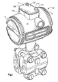
- Fig. 1 shows a pressure transmitter 10 in conjunction with a magnetic zero and span actuator 100 according to a first embodiment of the present invention.
- Transmitter 10 has a main housing 12 which, as is shown in Fig. 1 of the 03280 PCT application, typically defines a pair of internal chambers.
- the transmitter's energized electronics and terminals are housed in the associated one of the two chambers.
- the transmitter 10 includes threaded end caps 14 and 16 which screw into mating threads (not shown) on the housing 12 to seal the chambers from the external environment and provide explosion-proof characteristics to the housing.
- An O-ring (not shown) may be associated with end caps 14 and 16 to thereby provide a fluid- tight seal with transmitter housing 12.
- a circuit board which carries some of the energized transmitter circuitry is usually positioned within one of the two interior chambers of housing 12.
- the energized transmitter terminals and a portion of the current loop circuit are also usually located in the same chamber wherein the circuit board is positioned.
- Fig. 2 there is shown the position of the magnetically actuated zero and span reed switches 18 and 20 internal to housing 12.
- the reed switches are usually located in the same chamber wherein the circuit board is positioned.
- the reed switches 18 and 20 are positioned in the chamber adjacent the inner surface 12a of housing 12 so as to be located just below that portion of outer surface 12b of housing 12 where the actuator 100 is placed when it is desired to adjust the zero and span settings of the transmitter.
- the reed switches may be supported in their positions by appropriate means such as the supports posts mounted to the circuit board shown and described in the 03280 PCT application or may be soldered directly to the circuit board.
- Reed switches 18 and 20 are actuated by the single magnet included in actuator 100.
- the reed switches are normally open and do not close until the centerline of the single magnet in actuator 100 approaches the centerline of each of the reed switches.
- a detailed description of the internal construction and magnetic actuation of reed switches 18 and 20 is not needed herein as it is well known to those skilled in the art and is given in the 03280 PCT application.
- Actuator 100 includes a housing 102 which has a top cover 104 and a bottom cover 106.
- the top cover 104 is removable from bottom cover 106.
- the inside bottom surface 106a of the bottom cover 106 includes a track 108 which is parallel to the front and rear walls 106b and 106c of bottom cover 106.
- Actuator 100 also includes a single magnet 110 which fits into an opening 112c (shown in Fig. 5) on the underside 112a of magnet carrier 112.
- Underside 112a also has a slot 112b which is complementary in shape to track 108. Slot 112b allows magnet carrier 112 to slide on track 108 between right and left side walls 106d and 106e of bottom cover 106.
- Actuator 100 further includes first and second identical actuating arms 114 and 116 and the associated one of first and second essentially identical return springs 118 and 120.
- the only difference between return springs 118 and 120 is that return spring 118 is right hand wound and return spring 120 is left hand wound.
- Top cover 104 includes first and second openings 122 and 124 which are associated with a respective one of actuating arms 114 and 116. Since actuating arms 114 and 116 are identical and the return springs 118 and 120 associated therewith are, except as described above, essentially identical only actuating arm 114 and its associated return spring 118 need be described in detail.
- Actuating arm 114 includes flat portion 126 which at its right end has a cylindrical post 128 extending downwardly from its bottom surface 126a of flat portion 126.
- post 128 receives return spring 118.
- Extending upwardly from the top surface 126b of flat portion 126 at the same end that post 128 extends downwardly from is post 130.
- Post 130 includes a first essentially cylindrical portion 132 which has a groove 132a for receiving an O ring (not shown).
- Extending upwardly from cylindrical portion 132 is an essentially rectangular portion 134 which has a slot 134a in its top surface for receiving the complementary shaped tip of a tool such as a screwdriver therein.
- the rectangular portion 134 extends through opening 122 in top cover 102 and the cylindrical portion 132 is seated therein so that the O ring mounted in groove 132a provides a seal for the opening 122.
- an actuating pin 136 extends downwardly from surface 126a.
- Magnet carrier 112 includes first and second parallel slots 138 and 140 each associated with a respective one of the actuator pins 136 and 137 of actuator arms 114 and 116.
- slot 138 is associated with the actuating pin 136
- slot 140 is associated with the downwardly extending actuating pin 137 of actuating arm 116.
- the engagement of pin 136 with slot 138 will cause magnet carrier 112 to move on track 108 towards the right side wall 106d when the tip of the tool is inserted in slot 134a and the tool is given a counterclockwise torque.
- the engagement of pin 137 with slot 140 will cause magnet carrier 112 to move on track 108 towards the left side wall 106e when the tip of the tool is inserted in slot 135a and the tool is given a clockwise torque.
- FIG. 4a there is shown a section through actuator 100 with top cover 104 removed and the arms 114 and 116 in their null, i.e. unactuated positions.
- Slots 138 and 140 each contain a substantially double (or opposing) wall section 138a and 140a and a substantially single wall (or open) section 138b and 140b.
- this geometry of slots 138 and 140 allows the control of the position of magnet carrier 112 to be passed or alternated between actuating arms 114 and 116 while never allowing the magnet carrier to be in a state of uncontrolled motion or ambiguity.
- the geometry of slots 138 and 140 allows a desirable separation of the zero and span reset functions into two separate knobs and provides the actuator of the present invention as distinct advantage as compared to the prior art.
- actuating pin 136 and slot 138 there is shown an enlargement of actuating pin 136 and slot 138.
- Pin 136 extends downwardly from side 126a in a first tapered cylindrical portion 136a. Thereafter pin 136 continues to extend downwardly in a cylindrical portion 136b and terminates its downward extension in a substantially spherical knob 136c which engages the side walls 138c and 138d of slot 138.
- spring 118 has first and second arms 118a and 118b. While not shown in Fig. 3, bottom 126a of flat portion 126 has thereon means, such as ribs 126c and 126d shown in phantom in Fig. 4a, to which spring arms 118a is clipped when spring 118 is brought into assembled relationship with post 128.
- the interior of bottom cover 106 includes cylindrical post 106f (see Fig. 4a) which extends upwardly from the interior bottom surface 106a and terminates in a smaller diameter upwardly extending cylindrical post 106g. As is most clearly shown in Fig.
- bottom cover 106 further includes along its right sidewall 106d an upwardly extending shelf 106h and an upwardly extending rib 106i.
- post 106g engages a complementary opening (not shown) in the bottom of post 128 and, as is shown in Fig. 4a, arm 118b of spring 118 rests on shelf 106h and against rib 106i.
- bottom cover 106 also further includes a upwardly projecting shelf and rib 106j and 106k, which are associated with left sidewall 106e.
- actuator 100 When actuator 100 is assembled and a counterclockwise torque is applied to actuating arm 114, the magnet carrier 112 starts to move to the right on track 108 since actuating pin 136 is in slot 138.
- Actuating arm 114 continues to move counterclockwise in response to the torque applied to actuating arm 114, and as is shown in Fig. 4b, edge 126e of flat portion 126 comes into contact with rib 106i. The contacting of edge 126e with rib 106i prevents further rightward movement of the actuating arm 114, and therefore, of magnet carrier 112 on track 108.
- rib 106i functions as a stop when arm 114 is actuated and in a similar manner rib 106k functions as a stop when arm 116 is actuated. It should be appreciated that the magnet carrier has not contacted the associated side wall 106d or 106e when either arm 114 or 116 comes into contact with the associated stop 106i or 106k.
- Bottom cover 106 also includes first and second arms 106m and 106n which project upwardly from interior bottom surface 106a adjacent the interior of rear wall 106c.
- first and second arms 106m and 106n which project upwardly from interior bottom surface 106a adjacent the interior of rear wall 106c.
- Slidable magnet carrier 112 includes first and second upwardly extending tabs 112d and 112e. As is shown in Fig. 5, when actuator 100 is assembled, tabs 112c and 112d contact track 104a on the inside of cover 104 to help ensure that carrier 112 follows track 108 and magnet 110 remains essentially immobile in opening 112c when either of arms 114 and 116 are actuated.
- Opening 122 of top cover 104 has an upwardly extending sleeve 122a surrounding it.
- actuating arm 114 can only be actuated by inserting the tip of a screwdriver blade in slot 134a and applying a counterclockwise torque.
- Opening 124 of top cover 104 does not have any upwardly. extending sleeve surrounding it. As is shown in Fig. 4a, when actuator 100 is assembled rectangular portion 135 extends through opening 124 and without any sleeve portion 135 is accessible over essentially its entire length. Therefore, actuating arm 116 can be actuated not only by inserting the tip of a screwdriver blade into slot 135a but also by grasping rectangular portion 135 and applying a clockwise torque by hand.
- actuating arm 114 is used to reset the span of transmitter 10 while actuating arm 116 is used to reset the zero of the transmitter. Therefore, sleeve 122a ensures that the span of the transmitter can only be reset only by using a tool while the lack of an equivalent sleeve surrounding opening 124 allows the zero of the transmitter to be reset either by using a tool to apply the necessary torque or applying that torque by hand.
- actuator 100 will now be described in connection with Figs. 4a and 4b.
- Fig. 4a the actuator arms 114 and 116 are shown in their null position.
- arms 114 and 116 are held against stops 106m and 106n by a preload torque on springs 118 and 120 at the assembly of actuator 100, until an actuation torque is applied to either slot 134a or 135a.
- Actuating pins 136 and 137 are stationed in the single wall sections 138b and 140b of slots 138 and 140 when the actuator arms are in the null position.
- magnet carrier 112 In response to continued counterclockwise movement of pin 136, magnet carrier 112 continues to move to the right until edge 126e comes into contact with rib 106i. As is shown in Fig. 4b, further movement to the right of magnet carrier 112 is impeded by rib 106i.
- the centerline of magnet 110 is now essentially over the centerline of span reed switch 18.
- Reed switch 18 closes and the closing of the reed switch sets the span of transmitter 10. After the span of the transmitter is set, the torque that was applied to actuating arm 114 can be removed and the actuating arm moves clockwise and the magnet carrier moves to the left both as a result of the preload torque on spring 118. When the edge 126f comes into contact with stop 106m the magnetic carrier and the actuating arm have returned to the null position.
- the zero of the transmitter can be set in a manner similar to that described above for setting the span of the transmitter.
- a clockwise torque is applied to actuating arm 116 when actuating arms 114 and 116 are in the null position.
- arm 118 and pin 137 moves in the clockwise direction until the pin comes into contact with the left wall of slot 140.
- pin 137 causes the magnet carrier 112 to move to the left on track 108. Since the opening of the single wall section 138b is greater than the diameter of pin 136, the movement of the magnet carrier to the left is unimpeded by pin 136.
- the magnet carrier continues to move to the left in response to a clockwise torque on actuating arm 116 until the left edge of the flat portion of the actuating arm comes into contact with rib 106k.
- the centerline of magnet 110 is then essentially over the centerline of zero reed switch 20.
- Reed switch 20 closes and the closing of the reed switch sets the zero of transmitter 10.
- the torque that was applied to actuating arm 116 can be removed and the actuating arm moves counterclockwise and the magnet carrier moves to the right both as a result of the preload torque on spring 120.
- the right edge of the flat portion of actuating arm 116 comes into contact with stop 106n the magnetic carrier and the actuating arm have returned to the null position.
- the actuator 100 sits on the exterior of transmitter housing 12 and is removable therefrom.
- the inside bottom surface 106a of bottom 106 is complementary in shape to the shape of that portion of the transmitter housing upon which the actuator sits.
- the personnel trained to perform those adjustments seat actuator 100 in place on the exterior of the transmitter.
- the actuator 100 is removed as a single unit from the transmitter exterior thereby ensuring that the zero and span settings of the transmitter cannot be tampered with. It is not necessary to remove either the magnet 110 or the actuating arms 114 and 116 from the actuator in order to ensure that the transmitter's zero and span settings will not be tampered with. Additionally and in contrast to the prior art, the removal of actuator 100 does not leave any screw threads on the transmitter housing which may be exposed to undesirable conditions.
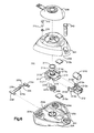
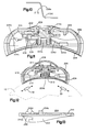
- the actuator 200 has a housing 202 with a bottom cover 204 and a top cover 206 which is removably mounted on bottom cover 204.
- Top cover 206 includes a hinged dust cap 208 which is opened when it is desired to adjust the zero and/or span reed switches 18 and 20.
- Actuator 200 also includes a single magnet 210 which is mounted in an opening 212e of a magnet carrier 212.
- Actuator 200 also includes a hub 213 which has included as a part thereof a control knob 214. The control knob and therefore the hub 213 is rotatable either in the clockwise and counterclockwise directions.
- Magnet carrier 212 has a first rearwardly projecting arm 212a having an opening 212b therein and a second rearwardly projecting arm 212c having an opening 212d therein. Arm 212c is parallel to arm 212a.
- Hub 213 has drive pins 216, 218 (see Fig.
- Control knob 214 includes slot 214a to receive the tip of a screwdriver blade therein to thereby apply either a clockwise or counterclockwise torque to the control knob.
- a counterclockwise torque applied to the control knob 214 will cause the hub 213 and therefore the magnet carrier 212 to rotate 90 ° in that direction so as to be brought essentially over the centerline of zero reed switch 18, as is shown in the simplified section of Fig. 12, to thereby close that reed switch and reset the zero of the transmitter.
- a clockwise torque applied to control knob 214 will, provided span safety lock pushbutton 220 is depressed to release a lock spring 236, cause the hub 213 and therefore the magnet carrier 212 to rotate 90 in that direction so as to be brought essentially over the centerline of span reed switch 20 to thereby close that reed switch and reset the span of the transmitter.
- Actuator 200 further includes an O-ring 211 which seals against an inside diameter 206a (see Fig. 8) in the roof 207 of top cover 206 to thereby provide a seal against water and contaminants entering the actuator 200.
- the hub 213 has a blind hole 213a (see Fig. 9) on axis in its bottom 213b which fits over a raised stud 204b in the floor 205 of bottom cover 204. Stud 204b establishes a rotation axis for the hub.
- the floor 205 of bottom cover 204 sustains axial thrust placed on the hub 213 by the screwdriver inserted in slot 214a.
- Actuator 200 also further includes a return spring 226.
- the spring 226 provides the torque to return the hub 213 and therefore control knob 214 to the null position after the knob is rotated either in the clockwise or counterclockwise directions to adjust the reed switches.
- the spring 226 is placed under a rotational preload as it is brought into assembled relationship with hub 213.
- Hub 213 includes slots 213c and 213d.
- Fig. 7 there is shown the spring 226 and hub 213 in assembled relationship.
- the free end 226a of the spring is placed in slot 213c and the free end 226b of the spring is placed in slot 213d to maintain the rotational preload.
- the portion 213e of hub 213 between slots 213c and 213d holds the free ends of the spring at a gap when the control knob 214 and therefore the hub 213 and the magnet carrier 212 are in the null, that is, unactuated, position.
- the roof 205 of top cover 204 includes a rib 206b.
- hub 213 also includes stops 213f and 213g.
- the roof 207 of top cover 206 (see Fig. 8) includes another rib 206c.
- stop 213f comes into contact with one edge of rib 206c.
- stop 213g comes into contact with the other edge of rib 206c.
- stops 213f and 213g of hub 213 and not the magnet carrier 212 that comes into contact with the associated edge of rib 206c to limit the travel of the magnet carrier to not more than 90 ° in the clockwise and counterclockwise directions.
- This interaction between stops 213f and 213g of hub 213 and rib 206c prevents stress on magnet carrier 212 when the carrier is rotated 90 in either direction from the null position and thereby reduces the likelihood that the magnet carrier will fail.
- control knob 214 is rotated in the clockwise direction then free end 226b is kept from moving by its associated edge of rib 206b and free end 226a can move in 213c as it is not kept from moving by its associated edge of rib 206b. This action spreads the spring in the opposite direction and provides the torque to return the spring to the null position.
- actuator 200 includes magnetic shunts 210a and 210b mounted in appropriate receptacles therefor in the floor 205 and the roof 207, respectively, to provide a short circuit magnetic path for the magnetic flux from magnet 210.
- the magnet 210 is positioned physically away from the reed switches and between shunts 210a and 210b. Therefore, shunts 210a and 210b together with a relative separation between the reed switches and the magnet, prevent magnet 210 from turning on the reed switches 18 and 20 when the magnet carrier is in the null position.
- Guide track 222 is associated with reed switch 18 and has a first end 222a adjacent the null position of magnet carrier 212 and a second end 222b adjacent the position of magnet carrier 212 when it is rotated 90 ° in the counterclockwise direction.
- Guide track 224 is associated with reed switch 20 and has a first end 224a adjacent the null position of magnet carrier 212 and a second end 224b adjacent the position of magnet carrier 212 when it is rotated 90 ° in the clockwise direction.
- guide track 222 increases in thickness from end 222a to 222b and guide track 224 increases in thickness from end 224a to 224b.
- control knob 214 is rotated 90 in the counterclockwise direction the magnet carrier 212 follows the curve of the floor 205 (see Fig. 6) of bottom cover 204 and the curve of guide track 222 to bring the centerline of magnet 210 essentially over the centerline of zero reed switch 18 (see the simplified section of the actuator 200 shown in Fig. 12) to thereby close that reed switch and reset the zero of the transmitter.
- the increasing thickness of track 222 from end 222a to end 222b ensures that magnet 210 is close to reed switch 18 when the magnet carrier has rotated 90 counterclockwise.
- floor 205 and guide tracks 222 and 224 form first and second curved paths to direct the rotational motion of the magnet carrier 212 as the control knob 214 is rotated in the clockwise or counterclockwise directions.
- These curved paths allow the magnet 210 to achieve both a close radial distance and parallel orientation to the reed switches 18 and 20.
- the close radial distance and the parallel orientation achieved by the magnet 210 of actuator 200 substantially helps the actuation of the reed switches by the magnet.
- the span safety switch pushbutton 220 includes an O-ring seal 234 and has a self retaining tip 220a.
- Lock spring 236 includes a first straight portion 236a, first and second ends 236b and 236c, second straight portion 236d and a transition 236e between portions 236a and 236d.
- First straight portion 236a has a slight upward slope from end 236b toward end 236c.
- Second straight portion 236d slopes downwardly toward end 236c from essentially upwardly extending transition portion 236e.
- the side of the hub 213 has a relatively thick portion 213h which extends from the rightmost edge of stop 213f to about the rightmost edge of portion 213e. At that point the side undergoes an abrupt reduction in its thickness at edge 213j to a relatively thin portion 213i which extends from about the rightmost edge of portion 213e to the leftmost edge of stop 213g.
- Lock spring 236 is designed to provide a predetermined breakaway torque that will allow edge 236e to slide by transition 213j in the hub edge and thereby allow rotation of the hub in the counterclockwise direction if an individual should try to rotate the hub in that direction without first depressing pushbutton 220.
- the predetermined breakaway torque is selected to avoid any physical damage to the hub and the lock spring.
- Hub 213 may be fabricated from series 300 stainless steel, lock spring 236 from 17-7 PH stainless steel heat treated to RH950 per ASTM 693 and the chamfer may be in the order of 25 ° on each edge.
- lock spring 236 also affords some additional detent action to the control knob 214 when it is in the null position. This detent action in combination with O-ring 211, and shunts 210a, 210b provides resistance to the control knob to help avoid undesirable vibration induced motion which might otherwise accidentally actuate the reed switches.
- the outside 203 of the bottom cover 204 includes first and second identical means 240 for mounting the actuator 200 to the transmitter housing. Only one of those means is shown in Fig. 13.
- the actuator housing 202 includes a single hole 241 to receive screw 242.
- the transmitter housing 12 includes first and second actuator receiving means (not shown) which are complementary in shape to the means 240.
- the actuator 200 is mounted on housing 12 by first interfitting each of the two actuator mounting means 240 with the associated one of the two complementary actuator receiving means on the transmitter and then tightening screw 242.
- the portion 240a of the actuator mounting means 240 shown in Fig. 13 rests on top of the associated actuator receiving means to thereby provide support for the actuator.
- the actuator housing 202 has sloped and low profile outside surfaces which avoid the placement of side forces on the actuator in the event someone climbing the installed equipment uses the transmitter 10 as a step.
Landscapes
- Physics & Mathematics (AREA)
- General Physics & Mathematics (AREA)
- Push-Button Switches (AREA)
- Arrangements For Transmission Of Measured Signals (AREA)
- Mechanical Control Devices (AREA)
- Control Of Position Or Direction (AREA)
- Transmission Devices (AREA)
- Transmitters (AREA)
- Transmission And Conversion Of Sensor Element Output (AREA)
- Switches That Are Operated By Magnetic Or Electric Fields (AREA)
- Reciprocating, Oscillating Or Vibrating Motors (AREA)
Abstract

Description
- The present invention relates to magnetic actuators such as those provided in transmitters used in industrial process control systems for the magnetic actuation of the zero and span adjustments of such transmitters.
- Two-wire transmitters (as well as three-wire and four-wire transmitters) find widespread use in industrial process control systems. A two-wire transmitter includes a pair of terminals which are connected in a current loop together with a power source and a load. The two-wire transmitter is powered by the loop current flowing through the current loop, and varies the magnitude of the loop current as a function of a parameter or condition which is sensed. Three and four wire transmitters have separate leads for supply current and outputs. In general, the transmitters comprise energized electrical circuits which are enclosed in a sealed housing such that ignition of any combustible atmosphere by faults or sparks from the energized circuit is contained in the housing.
- Although a variety of operating ranges are possible, the most widely used two-wire transmitter output varies from 4 to 20 milliamperes as a function of the sensed parameter. It is typical with a two-wire transmitter to provide adjustment of the transmitter so that a minimum or zero value of the parameter sensed corresponds to the minimum output (for example a loop current of 4 milliamperes) and that the maximum parameter value to be sensed corresponds to the maximum output (for example 20 milliamperes).
- The minimum and maximum parameter values will vary from one industrial process installation to another. It is desirable, therefore, to provide some means for setting the maximum and minimum output levels in the field, and this is done typically with electrically energized zero and span potentiometers sealed in the housing. With some transmitters, a housing cover must be removed to gain access to the potentiometers for adjustment, undesirably exposing the atmosphere surrounding the transmitter to the live circuits in the transmitter.
- A variety of techniques are available for adjusting the potentiometers while sealing potentially explosive atmospheres surrounding the transmitter from the electrically live circuits in the transmitter. In some transmitters, a rotary adjustment shaft for adjusting a potentiometer is closely fitted through a bore in the housing to provide a long flame path for quenching ignition in the housing before it reaches the atmosphere surrounding the housing. In yet another arrangement, the potentiometers are mechanically coupled to a relatively large bar magnet which is then rotated magnetically by another bar magnet outside the live circuit's enclosure. This arrangement with bar magnets can have the disadvantage of mechanical hysteresis, making precise span and zero setting difficult. Actuated switches are also used for setting span and zero in transmitters, such switches requiring an opening through the wall of the transmitter's housing to provide for mechanical coupling to the switch.
- For many process control environments, the transmitter itself is required to have an explosion-proof enclosure. This means that, if a spark takes place inside of the transmitter housing which ignites gases within the housing, no hot gases should be propagated from the interior of the transmitter to the exterior which could cause any surrounding combustible atmosphere to ignite.
- Providing for zero and span adjustments which are accessible from outside the transmitter (so that the housing would not have to be opened) is desirable, but makes it difficult (or expensive) to maintain the explosion-proof characteristics of the transmitter. One arrangement for adjusting the zero and span of a transmitter from outside of the housing is suggested in U.S. Patent No. 4,783,659 ("the '659 Patent") which issued on November 8, 1988. The transmitter described in the '659 Patent includes a communications circuit which can take a variety of forms including, as is shown in Fig. 1, magnetically actuated reed switches which are activated with a magnet from outside of the transmitter. The '659 Patent does not further show or describe the magnet or any structure for using the same to activate the reed switches.
- In addition to the actuator disclosed in the '659 Patent, other external span and zero actuators have, in the past, needed either bulky magnet pairs for transmitting rotational force or passages formed through the transmitter housing wall, so that one end of the actuating mechanism extends into the chamber which contains the transmitter electronics, while the other end is accessible from the exterior of the transmitter. In order to maintain explosion-proof characteristics, very long flame paths must be created with very tight tolerances. It is also important that the passages be sealed so that moisture cannot enter the transmitter housing through the span and zero actuator passages.
- As can be appreciated from the above, it would be desirable in providing for zero and span adjustments which are accessible from outside of the transmitter housing to eliminate the need for a long flame path and very tight tolerances. A transmitter which has externally accessible zero and span adjustment without the need for a long flame path and very tight tolerances is described in International Application Number PCT/US88/03280 which was published on 5 May 1989 as International Publication Number W089/04014 ("the 03280 PCT application").
- The transmitter described in the 03280 PCT application has zero and span magnetically actuated reed switches located in an interior chamber of the housing adjacent the housing's center wall. A relatively flat surface on the exterior of the transmitter housing has a recess formed therein. A pair of internally threaded blind holes extend downward from the recess into the center wall of the housing. A movable permanent magnet is situated in each blind hole. Each magnet is press fit into a lower recess of an associated screw which extend down into the associated blind hole. A spring is coaxially mounted on each magnet. A rubber washer is positioned below the head of each screw to provide an environmental seal for the blind hole. Access to the screws from the exterior of the housing is provided by a plate which is removably attached to the flat surface by a pair of screws.
- Adjustment of the zero and span settings for the transmitter described in the 03280 PCT application is accomplished by first removing the plate with a screwdriver to thereby allow a technician to have access to the upper ends of the screws associated with the zero and span movable magnets. The technician can then reset the zero and span settings of the transmitter by using a screwdriver to loosen the screws. The spring associated with the screw is under compression and the loosening of the screw allows the spring to push the screw up so that the centerline of the magnet is aligned with the centerline of the associated reed switch. The electronics to which the reed switches are connected then adjusts the zero or span settings of the transmitter. After adjusting the zero and span settings of the transmitter the technician should tighten the screw to recompress the spring and move the centerline of the magnet out of alignment with the centerline of the reed switch. In addition, the technician should reattach the plate to the flat surface.
- While the transmitter described in the 03280 PCT application does eliminate the need for a long flame path and very tight tolerances, it does not limit access to the movable magnets to only the personnel trained to perform the zero and span adjustments. The magnets are accessible to any individual who has access to the transmitter and a screwdriver. This makes the adjustment of the zero and span setting of the transmitter subject to tampering.
- According to the 03280 PCT application the adjustment of the zero and span setting of the transmitter described therein may be made resistant to tampering by removing the screws and magnets as well as the associated return springs and rubber washers from the housing. The screws, magnets, return springs and rubber washers are relatively small parts and may be easily lost or misplaced if removed from the blind holes. As described above, the rubber washers provide an environmental seal for the blind holes. The rubber washer does not provide an environmental seal for the moving parts of the zero or span adjustment mechanism during the adjustment of the zero or span settings because the washer is moved away from its sealing face when the screw is moved. Use of the adjustment mechanism may then allow environmental contaminants to accumulate in each blind hole. The accumulated environmental contaminants may cause a malfunction of the moving parts. Removal of the washers may expose the internal threads of the blind holes to conditions which may make it difficult to loosen and tighten the screws (and therefore adjust the zero and span settings of the transmitter) when the screws are reinserted into the holes.
- Respective aspects of the invention are set forth in claims 1 and 7.
- The invention will now be described by way of example with reference to the accompanying drawings, throughout which like parts are referred to by like references, and in which:
- Fig. 1 shows a magnetic zero and span actuator according to a first embodiment of the present invention, in conjunction with a pressure transmitter;
- Fig. 2 shows a portion of the pressure transmitter of Fig. 1 and the location of the zero and span reed switches internal to the pressure transmitter;
- Fig. 3 shows an exploded perspective of the first embodiment of the magnetic zero and span actuator;
- Fig. 3a shows an enlargement of the actuating pin of one of the actuating arms engaging the associated one of the two slots in the magnet carrier in the first embodiment;
- Figs. 4a and 4b are sections taken through the first embodiment of the actuator with the top cover of the actuator housing removed to show in Fig. 4a the position of the actuator arms and magnet carrier when the actuator is in its null position and in Fig. 4b the position of the actuator arms and the magnet carrier when one of the actuator arms is actuated to reset the span of the pressure transmitter;
- Fig. 5 is another section taken through the first embodiment of the actuator showing a high coercivity magnet in assembled relationship with the magnet carrier;
- Fig. 6 shows an exploded perspective of a second embodiment of the present invention;
- Fig. 7 shows the subassembly of the hub and the return spring used in the second embodiment for the actuator;
- Fig. 8 shows the roof of the top cover of the second embodiment for the actuator;
- Fig. 9 shows the bottom of the hub in the second embodiment;
- Fig. 10 shows an enlargement of the lock spring and hub interface when the second embodiment for the actuator is assembled and is in the null position;
- Fig. 11 shows a section through the assembled second embodiment for the actuator with the hub in the null position;
- Fig. 12 shows a simplified section through the second embodiment for the actuator with the high coercivity magnet and the magnet carrier rotated in the counterclockwise position so as to reset the zero of the transmitter; and
- Fig. 13 shows the outside of the bottom cover of the housing for the second embodiment of the actuator.
- Fig. 1 shows a
pressure transmitter 10 in conjunction with a magnetic zero andspan actuator 100 according to a first embodiment of the present invention.Transmitter 10 has amain housing 12 which, as is shown in Fig. 1 of the 03280 PCT application, typically defines a pair of internal chambers. The transmitter's energized electronics and terminals are housed in the associated one of the two chambers. Thetransmitter 10 includes threadedend caps housing 12 to seal the chambers from the external environment and provide explosion-proof characteristics to the housing. An O-ring (not shown) may be associated withend caps transmitter housing 12. - As is shown in the 03280 PCT application, a circuit board which carries some of the energized transmitter circuitry is usually positioned within one of the two interior chambers of
housing 12. The energized transmitter terminals and a portion of the current loop circuit are also usually located in the same chamber wherein the circuit board is positioned. - Referring now to Fig. 2, there is shown the position of the magnetically actuated zero and
span reed switches housing 12. The reed switches are usually located in the same chamber wherein the circuit board is positioned. The reed switches 18 and 20 are positioned in the chamber adjacent theinner surface 12a ofhousing 12 so as to be located just below that portion ofouter surface 12b ofhousing 12 where theactuator 100 is placed when it is desired to adjust the zero and span settings of the transmitter. The reed switches may be supported in their positions by appropriate means such as the supports posts mounted to the circuit board shown and described in the 03280 PCT application or may be soldered directly to the circuit board. - Reed switches 18 and 20 are actuated by the single magnet included in
actuator 100. The reed switches are normally open and do not close until the centerline of the single magnet inactuator 100 approaches the centerline of each of the reed switches. A detailed description of the internal construction and magnetic actuation ofreed switches - Referring now to Fig. 3, there is shown an exploded perspective of the magnetic zero and
span actuator 100 of the present invention.Actuator 100 includes ahousing 102 which has atop cover 104 and abottom cover 106. Thetop cover 104 is removable frombottom cover 106. Theinside bottom surface 106a of thebottom cover 106 includes atrack 108 which is parallel to the front andrear walls bottom cover 106. -
Actuator 100 also includes asingle magnet 110 which fits into anopening 112c (shown in Fig. 5) on the underside 112a ofmagnet carrier 112. Underside 112a also has aslot 112b which is complementary in shape to track 108.Slot 112b allowsmagnet carrier 112 to slide ontrack 108 between right and leftside walls bottom cover 106. -
Actuator 100 further includes first and second identical actuatingarms return spring 118 is right hand wound and returnspring 120 is left hand wound.Top cover 104 includes first andsecond openings arms arms arm 114 and its associatedreturn spring 118 need be described in detail. -
Actuating arm 114 includesflat portion 126 which at its right end has acylindrical post 128 extending downwardly from itsbottom surface 126a offlat portion 126. When actuator 100 is assembled,post 128 receivesreturn spring 118. Extending upwardly from thetop surface 126b offlat portion 126 at the same end that post 128 extends downwardly from ispost 130.Post 130 includes a first essentiallycylindrical portion 132 which has agroove 132a for receiving an O ring (not shown). Extending upwardly fromcylindrical portion 132 is an essentiallyrectangular portion 134 which has aslot 134a in its top surface for receiving the complementary shaped tip of a tool such as a screwdriver therein. When actuator 100 is assembled, therectangular portion 134 extends throughopening 122 intop cover 102 and thecylindrical portion 132 is seated therein so that the O ring mounted ingroove 132a provides a seal for theopening 122. - At the left end of
flat portion 126, anactuating pin 136 extends downwardly fromsurface 126a.Magnet carrier 112 includes first and secondparallel slots actuator arms slot 138 is associated with theactuating pin 136 andslot 140 is associated with the downwardly extendingactuating pin 137 of actuatingarm 116. When actuator 100 is assembled the actuating pins engage the associated one ofslots pin 136 withslot 138 will causemagnet carrier 112 to move ontrack 108 towards theright side wall 106d when the tip of the tool is inserted inslot 134a and the tool is given a counterclockwise torque. Also as will be described in more detail hereinafter, the engagement ofpin 137 withslot 140 will causemagnet carrier 112 to move ontrack 108 towards theleft side wall 106e when the tip of the tool is inserted inslot 135a and the tool is given a clockwise torque. - Referring now to Fig. 4a there is shown a section through
actuator 100 withtop cover 104 removed and thearms Slots wall section 138a and 140a and a substantially single wall (or open)section 138b and 140b. As will be described in more detail hereinafter, this geometry ofslots magnet carrier 112 to be passed or alternated between actuatingarms slots - Referring now to Fig. 3a, there is shown an enlargement of
actuating pin 136 andslot 138.Pin 136 extends downwardly fromside 126a in a first taperedcylindrical portion 136a. Thereafter pin 136 continues to extend downwardly in acylindrical portion 136b and terminates its downward extension in a substantiallyspherical knob 136c which engages theside walls 138c and 138d ofslot 138. - As can be seen from Fig. 3a, the
centerline 138c ofslot 138 is at an acute angle with respect to thecenterline 136d ofactuating pin 136. The reason therefore will be described below. - Returning now to Fig. 3, it can be seen that
spring 118 has first andsecond arms flat portion 126 has thereon means, such asribs spring arms 118a is clipped whenspring 118 is brought into assembled relationship withpost 128. The interior ofbottom cover 106 includescylindrical post 106f (see Fig. 4a) which extends upwardly from theinterior bottom surface 106a and terminates in a smaller diameter upwardly extendingcylindrical post 106g. As is most clearly shown in Fig. 4a, the interior ofbottom cover 106 further includes along itsright sidewall 106d an upwardly extendingshelf 106h and an upwardly extendingrib 106i. When actuator 100 is assembled,post 106g engages a complementary opening (not shown) in the bottom ofpost 128 and, as is shown in Fig. 4a,arm 118b ofspring 118 rests onshelf 106h and againstrib 106i. - The interior of
bottom cover 106 also further includes a upwardly projecting shelf andrib left sidewall 106e. When actuator 100 is assembled and a counterclockwise torque is applied to actuatingarm 114, themagnet carrier 112 starts to move to the right ontrack 108 since actuatingpin 136 is inslot 138.Actuating arm 114 continues to move counterclockwise in response to the torque applied to actuatingarm 114, and as is shown in Fig. 4b,edge 126e offlat portion 126 comes into contact withrib 106i. The contacting ofedge 126e withrib 106i prevents further rightward movement of theactuating arm 114, and therefore, ofmagnet carrier 112 ontrack 108. Therefore,rib 106i functions as a stop whenarm 114 is actuated and in asimilar manner rib 106k functions as a stop whenarm 116 is actuated. It should be appreciated that the magnet carrier has not contacted the associatedside wall arm stop -
Bottom cover 106 also includes first andsecond arms interior bottom surface 106a adjacent the interior ofrear wall 106c. As is shown most clearly in Fig. 4a, whenactuator 100 is assembled and the actuatingarms left edge 126f ofarm 114 rests againstrear arm 106m and a portion of the right edge ofarm 116 rests againstrear arm 106n. Therefore,rear arms arms Arms stops springs actuator 100, until an actuation torque is applied to eitherslot -
Slidable magnet carrier 112 includes first and second upwardly extendingtabs actuator 100 is assembled,tabs 112d contact track 104a on the inside ofcover 104 to help ensure thatcarrier 112 followstrack 108 andmagnet 110 remains essentially immobile inopening 112c when either ofarms - Opening 122 of
top cover 104 has an upwardly extending sleeve 122a surrounding it. As is shown in Fig. 1, whenactuator 100 is assembled therectangular portion 134 ofactuator arm 114 extends throughopening 122. Sleeve 122a surroundsrectangular portion 134 over a sufficient extent of its length such that only a relatively small part ofportion 134 is accessible making it difficult to graspportion 134 by hand. Therefore, actuatingarm 114 can only be actuated by inserting the tip of a screwdriver blade inslot 134a and applying a counterclockwise torque. - Opening 124 of
top cover 104 does not have any upwardly. extending sleeve surrounding it. As is shown in Fig. 4a, whenactuator 100 is assembled rectangular portion 135 extends throughopening 124 and without any sleeve portion 135 is accessible over essentially its entire length. Therefore, actuatingarm 116 can be actuated not only by inserting the tip of a screwdriver blade intoslot 135a but also by grasping rectangular portion 135 and applying a clockwise torque by hand. - In
actuator 100, actuatingarm 114 is used to reset the span oftransmitter 10 while actuatingarm 116 is used to reset the zero of the transmitter. Therefore, sleeve 122a ensures that the span of the transmitter can only be reset only by using a tool while the lack of an equivalentsleeve surrounding opening 124 allows the zero of the transmitter to be reset either by using a tool to apply the necessary torque or applying that torque by hand. - The operation of
actuator 100 will now be described in connection with Figs. 4a and 4b. Referring first to Fig. 4a theactuator arms null position arms stops springs actuator 100, until an actuation torque is applied to eitherslot single wall sections 138b and 140b ofslots - The application of a counterclockwise torque to
arm 114 causes the arm and therefore pin 136 to move in the counterclockwise direction from the null position. During this motion ofarm 114,arm 116 is held in the null position by the preload torque ofspring 120. Continued counterclockwise movement of the pin brings thepin 136 into contact withside wall 138c ofslot 138. At that point the continued application of counterclockwise torque to actuatingarm 114 causes the magnet carrier to begin to move to the right ontrack 108. Since the opening of the single wall section 140b is greater than the diameter ofpin 137, the movement of the magnet carrier to the right is unimpeded bypin 137. - In response to continued counterclockwise movement of
pin 136,magnet carrier 112 continues to move to the right untiledge 126e comes into contact withrib 106i. As is shown in Fig. 4b, further movement to the right ofmagnet carrier 112 is impeded byrib 106i. The centerline ofmagnet 110 is now essentially over the centerline ofspan reed switch 18.Reed switch 18 closes and the closing of the reed switch sets the span oftransmitter 10. After the span of the transmitter is set, the torque that was applied to actuatingarm 114 can be removed and the actuating arm moves clockwise and the magnet carrier moves to the left both as a result of the preload torque onspring 118. When theedge 126f comes into contact withstop 106m the magnetic carrier and the actuating arm have returned to the null position. - The zero of the transmitter can be set in a manner similar to that described above for setting the span of the transmitter. To set the zero, a clockwise torque is applied to actuating
arm 116 when actuatingarms arm 118 and pin 137 moves in the clockwise direction until the pin comes into contact with the left wall ofslot 140. Continued clockwise movement ofpin 137 causes themagnet carrier 112 to move to the left ontrack 108. Since the opening of thesingle wall section 138b is greater than the diameter ofpin 136, the movement of the magnet carrier to the left is unimpeded bypin 136. - The magnet carrier continues to move to the left in response to a clockwise torque on actuating
arm 116 until the left edge of the flat portion of the actuating arm comes into contact withrib 106k. The centerline ofmagnet 110 is then essentially over the centerline of zeroreed switch 20.Reed switch 20 closes and the closing of the reed switch sets the zero oftransmitter 10. After the zero of the transmitter is set, the torque that was applied to actuatingarm 116 can be removed and the actuating arm moves counterclockwise and the magnet carrier moves to the right both as a result of the preload torque onspring 120. When the right edge of the flat portion of actuatingarm 116 comes into contact withstop 106n the magnetic carrier and the actuating arm have returned to the null position. - A detailed description of how the zero or the span of a transmitter is set when the zero or span reed switch closes is not needed herein as it is well known to those skilled in the art. Such a description is given in the 03280 PCT application.
- Referring once again to Figs. 1 and 3, it is seen that the
actuator 100 sits on the exterior oftransmitter housing 12 and is removable therefrom. Theinside bottom surface 106a ofbottom 106 is complementary in shape to the shape of that portion of the transmitter housing upon which the actuator sits. When it is desired to set either the zero and/or the span oftransmitter 10, the personnel trained to perform those adjustments seat actuator 100 in place on the exterior of the transmitter. After the zero and/or span have been set, theactuator 100 is removed as a single unit from the transmitter exterior thereby ensuring that the zero and span settings of the transmitter cannot be tampered with. It is not necessary to remove either themagnet 110 or the actuatingarms actuator 100 does not leave any screw threads on the transmitter housing which may be exposed to undesirable conditions. - Referring now to Fig. 6, there is shown an exploded perspective for a
second embodiment 200 for the actuator of the present invention. Theactuator 200 has a housing 202 with abottom cover 204 and atop cover 206 which is removably mounted onbottom cover 204.Top cover 206 includes a hingeddust cap 208 which is opened when it is desired to adjust the zero and/orspan reed switches -
Actuator 200 also includes asingle magnet 210 which is mounted in anopening 212e of amagnet carrier 212.Actuator 200 also includes ahub 213 which has included as a part thereof acontrol knob 214. The control knob and therefore thehub 213 is rotatable either in the clockwise and counterclockwise directions.Magnet carrier 212 has a firstrearwardly projecting arm 212a having anopening 212b therein and a secondrearwardly projecting arm 212c having anopening 212d therein.Arm 212c is parallel toarm 212a.Hub 213 has drive pins 216, 218 (see Fig. 9) and theopenings pins carrier 212 can be rotated only about the drive pins whencontrol knob 214 is rotated in the clockwise and counterclockwise directions. -
Control knob 214 includesslot 214a to receive the tip of a screwdriver blade therein to thereby apply either a clockwise or counterclockwise torque to the control knob. As will be described in more detail below whenactuator 200 is assembled a counterclockwise torque applied to thecontrol knob 214 will cause thehub 213 and therefore themagnet carrier 212 to rotate 90 ° in that direction so as to be brought essentially over the centerline of zeroreed switch 18, as is shown in the simplified section of Fig. 12, to thereby close that reed switch and reset the zero of the transmitter. Also as will be described in more detail below a clockwise torque applied to controlknob 214 will, provided spansafety lock pushbutton 220 is depressed to release alock spring 236, cause thehub 213 and therefore themagnet carrier 212 to rotate 90 in that direction so as to be brought essentially over the centerline ofspan reed switch 20 to thereby close that reed switch and reset the span of the transmitter. -
Actuator 200 further includes an O-ring 211 which seals against aninside diameter 206a (see Fig. 8) in theroof 207 oftop cover 206 to thereby provide a seal against water and contaminants entering theactuator 200. Thehub 213 has ablind hole 213a (see Fig. 9) on axis in its bottom 213b which fits over a raisedstud 204b in thefloor 205 ofbottom cover 204.Stud 204b establishes a rotation axis for the hub. Thefloor 205 ofbottom cover 204 sustains axial thrust placed on thehub 213 by the screwdriver inserted inslot 214a. -
Actuator 200 also further includes areturn spring 226. Thespring 226 provides the torque to return thehub 213 and therefore controlknob 214 to the null position after the knob is rotated either in the clockwise or counterclockwise directions to adjust the reed switches. Thespring 226 is placed under a rotational preload as it is brought into assembled relationship withhub 213.Hub 213 includesslots - Referring to Fig. 7, there is shown the
spring 226 andhub 213 in assembled relationship. As can be seen from a comparison of Figs. 6 and 7 whenspring 226 is brought into assembled relationship withhub 213, thefree end 226a of the spring is placed inslot 213c and thefree end 226b of the spring is placed inslot 213d to maintain the rotational preload. Theportion 213e ofhub 213 betweenslots control knob 214 and therefore thehub 213 and themagnet carrier 212 are in the null, that is, unactuated, position. As is shown in Fig. 8, theroof 205 oftop cover 204 includes arib 206b. When theactuator 200 is assembled and in the null position the free ends 226a and 226b ofspring 226 rest against an associated edge of therib 206b. - As is shown in Fig. 6,
hub 213 also includesstops roof 207 of top cover 206 (see Fig. 8) includes anotherrib 206c. When the hub is rotated 90 in thecounterclockwise direction stop 213f comes into contact with one edge ofrib 206c. When thehub 213 is rotated 90 in theclockwise direction stop 213g comes into contact with the other edge ofrib 206c. It should be appreciated that it is stops 213f and 213g ofhub 213 and not themagnet carrier 212 that comes into contact with the associated edge ofrib 206c to limit the travel of the magnet carrier to not more than 90 ° in the clockwise and counterclockwise directions. This interaction betweenstops hub 213 andrib 206c prevents stress onmagnet carrier 212 when the carrier is rotated 90 in either direction from the null position and thereby reduces the likelihood that the magnet carrier will fail. - As is shown in Fig. 7, when the
spring 226 and thehub 213 are in assembled relationship free ends 226a and 226b of the spring project upwardly throughslots actuator 200 is assembled the free ends of the spring come into contact with the edges ofrib 206b. Ifcontrol knob 214 is rotated in the counterclockwise direction thenfree end 226a is kept from moving by its associated edge ofrib 206b andfree end 226b can move in 213d as it is not kept from moving by its associated edge ofrib 206b. This action spreads the spring in one direction and provides the torque to return the spring to the null position. Ifcontrol knob 214 is rotated in the clockwise direction thenfree end 226b is kept from moving by its associated edge ofrib 206b andfree end 226a can move in 213c as it is not kept from moving by its associated edge ofrib 206b. This action spreads the spring in the opposite direction and provides the torque to return the spring to the null position. - It is the
spring 226,portion 213e ofhub 213 andrib 206b which allow thecontrol knob 214 and therefore thehub 213 and themagnet carrier 212 to rotate 90 degrees in either direction from the null position and have a spring return to an "off" position that is defined by a deadband region of no spring force on thecontrol knob 214. The deadband region has a width which is no greater than the width ofportion 213e. - When the
control knob 214 is in the null position themagnet carrier 212 and thereforesingle magnet 210 is midway betweenreed switches actuator 200 includesmagnetic shunts floor 205 and theroof 207, respectively, to provide a short circuit magnetic path for the magnetic flux frommagnet 210. When thecontrol knob 214 is in the null position themagnet 210 is positioned physically away from the reed switches and betweenshunts magnet 210 from turning on the reed switches 18 and 20 when the magnet carrier is in the null position. - Referring now to Fig. 8, there is shown first and second curved guide tracks 222 and 224 in the
roof 207 oftop cover 206.Guide track 222 is associated withreed switch 18 and has afirst end 222a adjacent the null position ofmagnet carrier 212 and asecond end 222b adjacent the position ofmagnet carrier 212 when it is rotated 90 ° in the counterclockwise direction.Guide track 224 is associated withreed switch 20 and has afirst end 224a adjacent the null position ofmagnet carrier 212 and asecond end 224b adjacent the position ofmagnet carrier 212 when it is rotated 90 ° in the clockwise direction. - As can be seen in Fig. 8,
guide track 222 increases in thickness fromend 222a to 222b andguide track 224 increases in thickness fromend 224a to 224b. Whencontrol knob 214 is rotated 90 in the counterclockwise direction themagnet carrier 212 follows the curve of the floor 205 (see Fig. 6) ofbottom cover 204 and the curve ofguide track 222 to bring the centerline ofmagnet 210 essentially over the centerline of zero reed switch 18 (see the simplified section of theactuator 200 shown in Fig. 12) to thereby close that reed switch and reset the zero of the transmitter. The increasing thickness oftrack 222 fromend 222a to end 222b ensures thatmagnet 210 is close toreed switch 18 when the magnet carrier has rotated 90 counterclockwise. Whencontrol knob 214 is rotated 90 in the clockwise direction, provided spansafety lock pushbutton 220 is depressed to releaselock spring 236, the magnet carrier follows the curve of thefloor 205 andguide track 224 to bring the centerline ofmagnet 210 essentially over the centerline ofspan reed switch 20 to thereby close that reed switch and reset the span of the transmitter. The increasing thickness oftrack 224 fromend 224a to end 224b ensures thatmagnet 210 is close toreed switch 20 when the magnet carrier has rotated 90 clockwise. - It should be appreciated that
floor 205 and guidetracks magnet carrier 212 as thecontrol knob 214 is rotated in the clockwise or counterclockwise directions. These curved paths allow themagnet 210 to achieve both a close radial distance and parallel orientation to the reed switches 18 and 20. The close radial distance and the parallel orientation achieved by themagnet 210 ofactuator 200 substantially helps the actuation of the reed switches by the magnet. - Referring once again to Fig. 6, it can be seen that the span
safety switch pushbutton 220 includes an O-ring seal 234 and has aself retaining tip 220a.Lock spring 236 includes a firststraight portion 236a, first and second ends 236b and 236c, secondstraight portion 236d and atransition 236e betweenportions straight portion 236a has a slight upward slope fromend 236b towardend 236c. Secondstraight portion 236d slopes downwardly towardend 236c from essentially upwardly extendingtransition portion 236e. - When actuator 200 is fully assembled the
lower end 220a ofpushbutton 220 is in contact with a firststraight portion 236a oflock spring 236 near oneend 236b of the lock spring. As is shown in Fig. 11 when the actuator is assembledend 236b is seated in an upwardly projecting complementary shapedreceptacle 204c infloor 205 andend 236c rests on the top of upward projectingribs 204d in thefloor 205. It should be appreciated that the lock spring does not rotate when the hub is rotated. - Referring once again to Fig. 7, it is seen that the side of the
hub 213 has a relativelythick portion 213h which extends from the rightmost edge ofstop 213f to about the rightmost edge ofportion 213e. At that point the side undergoes an abrupt reduction in its thickness atedge 213j to a relativelythin portion 213i which extends from about the rightmost edge ofportion 213e to the leftmost edge ofstop 213g. - When actuator 200 is assembled and is in the null position the
upward transition 236e oflock spring 236 is just to the left ofedge 213j. This location of the upward transition of the lock spring relative to edge 213j in the null position, except as described below, prevents rotation of the hub in the counterclockwise direction unless the pushbutton 220 (see Fig. 6) is depressed to thereby push down the lock spring. While not shown in Fig. 6,floor 205 includes an upwardly circular post which is positioned to be just below the point onlock spring 236a which is contacted byend 220a of the pushbutton. The post limits the downward motion of the lock spring when it is contacted byend 220a. - Referring now to Fig. 10, there is shown an enlargement of the interface between
lock spring edge 236e andtransition 213j of the hub edge.Lock spring 236 is designed to provide a predetermined breakaway torque that will allowedge 236e to slide bytransition 213j in the hub edge and thereby allow rotation of the hub in the counterclockwise direction if an individual should try to rotate the hub in that direction without firstdepressing pushbutton 220. The predetermined breakaway torque is selected to avoid any physical damage to the hub and the lock spring. - In designing the lock spring it was found that the
slight chamfer 236f in the transition shown in Fig. 10 helped to maintain the contact area betweenedge 236e and thetransition 213j even after repeated torquing of the hub in the counterclockwise direction without depressing thepushbutton 220.Hub 213 may be fabricated from series 300 stainless steel,lock spring 236 from 17-7 PH stainless steel heat treated to RH950 per ASTM 693 and the chamfer may be in the order of 25 ° on each edge. - In addition to the function described above,
lock spring 236 also affords some additional detent action to thecontrol knob 214 when it is in the null position. This detent action in combination with O-ring 211, andshunts - Referring now to Figs. 6 and 13, the manner in which the
actuator 200 is mounted to the transmittermain housing 12 when it is desired to reset the zero and/or span reed switches will now be described. The outside 203 of thebottom cover 204 includes first and second identical means 240 for mounting theactuator 200 to the transmitter housing. Only one of those means is shown in Fig. 13. In addition and as is shown in Fig. 6 the actuator housing 202 includes asingle hole 241 to receivescrew 242. - The
transmitter housing 12 includes first and second actuator receiving means (not shown) which are complementary in shape to themeans 240. Theactuator 200 is mounted onhousing 12 by first interfitting each of the two actuator mounting means 240 with the associated one of the two complementary actuator receiving means on the transmitter and then tighteningscrew 242. When the actuator is mounted on the transmitter housing, theportion 240a of the actuator mounting means 240 shown in Fig. 13 rests on top of the associated actuator receiving means to thereby provide support for the actuator. As can be seen in Fig. 6, the actuator housing 202 has sloped and low profile outside surfaces which avoid the placement of side forces on the actuator in the event someone climbing the installed equipment uses thetransmitter 10 as a step. - It is to be understood that the description of the preferred embodiments are intended to be only illustrative, rather than exhaustive, of the present invention. Those of ordinary skill will be able to make certain additions, deletions, and/or modifications to those embodiments of the disclosed subject matter without departing from the scope of the invention.
Claims (10)
wherein said magnet (110) actuates only said first switch (18) or a third position wherein said magnet (110) actuates only said second switch (20).
Applications Claiming Priority (2)
| Application Number | Priority Date | Filing Date | Title |
|---|---|---|---|
| US975637 | 1992-11-13 | ||
| US07/975,637 US5369386A (en) | 1992-11-13 | 1992-11-13 | Removable magnetic zero/span actuator for a transmitter |
Publications (2)
| Publication Number | Publication Date |
|---|---|
| EP0597570A1 true EP0597570A1 (en) | 1994-05-18 |
| EP0597570B1 EP0597570B1 (en) | 1998-05-20 |
Family
ID=25523232
Family Applications (1)
| Application Number | Title | Priority Date | Filing Date |
|---|---|---|---|
| EP93306061A Expired - Lifetime EP0597570B1 (en) | 1992-11-13 | 1993-07-30 | Magnetic actuators |
Country Status (12)
| Country | Link |
|---|---|
| US (1) | US5369386A (en) |
| EP (1) | EP0597570B1 (en) |
| JP (1) | JPH06223291A (en) |
| KR (1) | KR940012222A (en) |
| CN (1) | CN1105772A (en) |
| AU (1) | AU673007B2 (en) |
| BR (1) | BR9304413A (en) |
| CA (1) | CA2100525C (en) |
| DE (1) | DE69318673T2 (en) |
| ES (1) | ES2116414T3 (en) |
| MX (1) | MX9306523A (en) |
| NO (1) | NO932878D0 (en) |
Cited By (3)
| Publication number | Priority date | Publication date | Assignee | Title |
|---|---|---|---|---|
| RU2212727C2 (en) * | 2001-10-01 | 2003-09-20 | Закрытое акционерное общество "Первый Московский завод радиодеталей" | Contactless position switch |
| US8044656B2 (en) | 2006-04-11 | 2011-10-25 | Abb S.P.A. | Device for calibration of a field transmitter |
| RU2466474C1 (en) * | 2011-08-09 | 2012-11-10 | Федеральное Государственное Унитарное Предприятие "Государственный научно-производственный ракетно-космический центр "ЦСКБ-Прогресс" (ФГУП "ГНПРКЦ "ЦСКБ-Прогресс") | Immediate action switch |
Families Citing this family (40)
| Publication number | Priority date | Publication date | Assignee | Title |
|---|---|---|---|---|
| WO2001024594A2 (en) | 1999-09-28 | 2001-04-05 | Rosemount Inc. | Environmentally sealed instrument loop adapter |
| US6765968B1 (en) | 1999-09-28 | 2004-07-20 | Rosemount Inc. | Process transmitter with local databus |
| US7134354B2 (en) | 1999-09-28 | 2006-11-14 | Rosemount Inc. | Display for process transmitter |
| US6484107B1 (en) | 1999-09-28 | 2002-11-19 | Rosemount Inc. | Selectable on-off logic modes for a sensor module |
| US6487912B1 (en) | 1999-09-28 | 2002-12-03 | Rosemount Inc. | Preinstallation of a pressure sensor module |
| US6571132B1 (en) | 1999-09-28 | 2003-05-27 | Rosemount Inc. | Component type adaptation in a transducer assembly |
| US6510740B1 (en) | 1999-09-28 | 2003-01-28 | Rosemount Inc. | Thermal management in a pressure transmitter |
| US6546805B2 (en) | 2000-03-07 | 2003-04-15 | Rosemount Inc. | Process fluid transmitter with an environmentally sealed service block |
| USD441672S1 (en) | 2000-03-21 | 2001-05-08 | Rosemount Inc. | Pressure transmitter with dual inlet base and economy housing |
| USD439180S1 (en) | 2000-03-21 | 2001-03-20 | Rosemount Inc. | Pressure transmitter with single inlet base and single compartment housing |
| USD439181S1 (en) | 2000-03-21 | 2001-03-20 | Rosemount Inc. | Pressure transmitter with dual inlet base and dual compartment housing |
| USD439178S1 (en) | 2000-03-21 | 2001-03-20 | Rosemount Inc. | Pressure transmitter with dual inlet base and single compartment housing |
| USD439179S1 (en) | 2000-03-21 | 2001-03-20 | Rosemount Inc. | Pressure transmitter with single inlet base and dual compartment housing |
| USD439177S1 (en) | 2000-03-21 | 2001-03-20 | Rosemount Inc. | Pressure transmitter with single inlet base and economy housing |
| US6662662B1 (en) | 2000-05-04 | 2003-12-16 | Rosemount, Inc. | Pressure transmitter with improved isolator system |
| US6504489B1 (en) | 2000-05-15 | 2003-01-07 | Rosemount Inc. | Process control transmitter having an externally accessible DC circuit common |
| US6480131B1 (en) | 2000-08-10 | 2002-11-12 | Rosemount Inc. | Multiple die industrial process control transmitter |
| DE10064809A1 (en) * | 2000-12-22 | 2002-06-27 | Endress & Hauser Gmbh & Co Kg | Operating parameters adjusting device for a pressure gauge or transducer, such as the null point and operating range |
| US6516672B2 (en) | 2001-05-21 | 2003-02-11 | Rosemount Inc. | Sigma-delta analog to digital converter for capacitive pressure sensor and process transmitter |
| US6684711B2 (en) | 2001-08-23 | 2004-02-03 | Rosemount Inc. | Three-phase excitation circuit for compensated capacitor industrial process control transmitters |
| USD472831S1 (en) | 2001-10-11 | 2003-04-08 | Rosemount Inc. | Single inlet base pressure instrument |
| USD471829S1 (en) | 2001-10-11 | 2003-03-18 | Rosemount Inc. | Dual inlet base pressure instrument |
| US7773715B2 (en) | 2002-09-06 | 2010-08-10 | Rosemount Inc. | Two wire transmitter with isolated can output |
| US7109883B2 (en) | 2002-09-06 | 2006-09-19 | Rosemount Inc. | Low power physical layer for a bus in an industrial transmitter |
| US7036381B2 (en) * | 2004-06-25 | 2006-05-02 | Rosemount Inc. | High temperature pressure transmitter assembly |
| CA2621030C (en) * | 2005-09-02 | 2011-10-11 | Abb Inc. | Modular gas chromatograph |
| US7525419B2 (en) | 2006-01-30 | 2009-04-28 | Rosemount Inc. | Transmitter with removable local operator interface |
| EP3254663B8 (en) | 2007-06-18 | 2021-06-30 | SonicSensory Inc. | Vibrating footwear device and entertainment system for use therewith |
| CN101516167B (en) * | 2008-02-18 | 2011-11-09 | 鸿富锦精密工业(深圳)有限公司 | Electronic device |
| US8334788B2 (en) | 2010-03-04 | 2012-12-18 | Rosemount Inc. | Process variable transmitter with display |
| JP5691653B2 (en) * | 2011-03-03 | 2015-04-01 | 東亜ディーケーケー株式会社 | Electric conductivity meter |
| USD712765S1 (en) * | 2012-03-09 | 2014-09-09 | Honeywell International Inc. | Compact wired transmitter with external configuration features for hazardous locations |
| WO2015064610A1 (en) * | 2013-10-29 | 2015-05-07 | アズビル株式会社 | Switch structure and explosion-proof device |
| US10372021B2 (en) * | 2014-12-31 | 2019-08-06 | Anthony S Lenzo | Triple axis magnetic actuator through non-metallic substrate |
| US10312908B2 (en) * | 2015-09-28 | 2019-06-04 | Eaton Intelligent Power Limited | Nested magnetic controls for industrial enclosures |
| US11239015B2 (en) | 2015-09-28 | 2022-02-01 | Eaton Intelligent Power Limited | Magnetic controls for industrial enclosures |
| DE102017110009B4 (en) * | 2017-05-09 | 2023-03-09 | Auma Riester Gmbh & Co. Kg | Actuator with control device and associated method of operation |
| IT201800005373A1 (en) * | 2018-05-15 | 2019-11-15 | Actuator device for the change of status of an electronically controlled underwater equipment and related system | |
| USD1046782S1 (en) * | 2021-01-12 | 2024-10-15 | Micro Motion, Inc. | Electronic housing |
| USD1063846S1 (en) * | 2021-01-12 | 2025-02-25 | Micro Motion, Inc. | Electronics housing for a flowmeter |
Citations (7)
| Publication number | Priority date | Publication date | Assignee | Title |
|---|---|---|---|---|
| DE7419684U (en) * | 1974-06-07 | 1974-09-19 | Borgmann W Gmbh | Encapsulated electrical device |
| DE2758856A1 (en) * | 1977-12-30 | 1979-07-05 | Conducta Mess & Regeltech | Analytical process instrument - with zero and steepness adjustment by permanent magnets through non-magnetic wall |
| DE2804952A1 (en) * | 1978-02-06 | 1979-08-09 | Siemens Ag | Operating device for magnetically controlled switch - with contacts mounted on case wall and operated by magnet placed near them |
| DE3345822A1 (en) * | 1983-12-17 | 1985-06-27 | Josef Heinrichs Meßgeräte, 5000 Köln | Electrical switching device for use in explosion-endangered areas |
| GB2197075A (en) * | 1986-11-06 | 1988-05-11 | Eaton Corp | Explosion proof housing with magnetically actuated input device |
| EP0310761A1 (en) * | 1987-10-01 | 1989-04-12 | Berwind Corporation | Capacitance-type material level indicator |
| WO1989004014A1 (en) * | 1987-10-22 | 1989-05-05 | Rosemount Inc. | Transmitter with magnetic zero/span actuator |
Family Cites Families (6)
| Publication number | Priority date | Publication date | Assignee | Title |
|---|---|---|---|---|
| US3469042A (en) * | 1967-11-28 | 1969-09-23 | Gen Motors Corp | Rack and pinion switch with tiltable bridging contact and stepped fixed contacts |
| US3527903A (en) * | 1968-07-15 | 1970-09-08 | Jack C Holland | Combination gauge switch |
| US4783659A (en) * | 1986-08-22 | 1988-11-08 | Rosemount Inc. | Analog transducer circuit with digital control |
| JPH0323639Y2 (en) * | 1986-10-13 | 1991-05-23 | ||
| US4737751A (en) * | 1987-02-17 | 1988-04-12 | George Risk | Robbery alarm switch |
| US4965417A (en) * | 1989-03-27 | 1990-10-23 | Massie Philip E | Foot-operated control |
-
1992
- 1992-11-13 US US07/975,637 patent/US5369386A/en not_active Expired - Fee Related
-
1993
- 1993-07-14 CA CA002100525A patent/CA2100525C/en not_active Expired - Fee Related
- 1993-07-30 DE DE69318673T patent/DE69318673T2/en not_active Expired - Fee Related
- 1993-07-30 EP EP93306061A patent/EP0597570B1/en not_active Expired - Lifetime
- 1993-07-30 ES ES93306061T patent/ES2116414T3/en not_active Expired - Lifetime
- 1993-08-12 NO NO932878A patent/NO932878D0/en unknown
- 1993-08-17 KR KR1019930015879A patent/KR940012222A/en not_active Abandoned
- 1993-10-20 MX MX9306523A patent/MX9306523A/en not_active IP Right Cessation
- 1993-10-22 AU AU50207/93A patent/AU673007B2/en not_active Ceased
- 1993-10-29 BR BR9304413A patent/BR9304413A/en not_active Application Discontinuation
- 1993-11-12 JP JP5306127A patent/JPH06223291A/en not_active Withdrawn
- 1993-11-13 CN CN93119370A patent/CN1105772A/en active Pending
Patent Citations (7)
| Publication number | Priority date | Publication date | Assignee | Title |
|---|---|---|---|---|
| DE7419684U (en) * | 1974-06-07 | 1974-09-19 | Borgmann W Gmbh | Encapsulated electrical device |
| DE2758856A1 (en) * | 1977-12-30 | 1979-07-05 | Conducta Mess & Regeltech | Analytical process instrument - with zero and steepness adjustment by permanent magnets through non-magnetic wall |
| DE2804952A1 (en) * | 1978-02-06 | 1979-08-09 | Siemens Ag | Operating device for magnetically controlled switch - with contacts mounted on case wall and operated by magnet placed near them |
| DE3345822A1 (en) * | 1983-12-17 | 1985-06-27 | Josef Heinrichs Meßgeräte, 5000 Köln | Electrical switching device for use in explosion-endangered areas |
| GB2197075A (en) * | 1986-11-06 | 1988-05-11 | Eaton Corp | Explosion proof housing with magnetically actuated input device |
| EP0310761A1 (en) * | 1987-10-01 | 1989-04-12 | Berwind Corporation | Capacitance-type material level indicator |
| WO1989004014A1 (en) * | 1987-10-22 | 1989-05-05 | Rosemount Inc. | Transmitter with magnetic zero/span actuator |
Cited By (3)
| Publication number | Priority date | Publication date | Assignee | Title |
|---|---|---|---|---|
| RU2212727C2 (en) * | 2001-10-01 | 2003-09-20 | Закрытое акционерное общество "Первый Московский завод радиодеталей" | Contactless position switch |
| US8044656B2 (en) | 2006-04-11 | 2011-10-25 | Abb S.P.A. | Device for calibration of a field transmitter |
| RU2466474C1 (en) * | 2011-08-09 | 2012-11-10 | Федеральное Государственное Унитарное Предприятие "Государственный научно-производственный ракетно-космический центр "ЦСКБ-Прогресс" (ФГУП "ГНПРКЦ "ЦСКБ-Прогресс") | Immediate action switch |
Also Published As
| Publication number | Publication date |
|---|---|
| EP0597570B1 (en) | 1998-05-20 |
| KR940012222A (en) | 1994-06-23 |
| NO932878D0 (en) | 1993-08-12 |
| BR9304413A (en) | 1994-06-28 |
| ES2116414T3 (en) | 1998-07-16 |
| DE69318673T2 (en) | 1998-09-10 |
| AU5020793A (en) | 1994-05-26 |
| US5369386A (en) | 1994-11-29 |
| CN1105772A (en) | 1995-07-26 |
| DE69318673D1 (en) | 1998-06-25 |
| CA2100525A1 (en) | 1994-05-14 |
| AU673007B2 (en) | 1996-10-24 |
| JPH06223291A (en) | 1994-08-12 |
| NO932878L (en) | 1994-05-16 |
| CA2100525C (en) | 1997-01-14 |
| MX9306523A (en) | 1994-05-31 |
Similar Documents
| Publication | Publication Date | Title |
|---|---|---|
| US5369386A (en) | Removable magnetic zero/span actuator for a transmitter | |
| US4395608A (en) | Safety switch assemblies | |
| US9853429B2 (en) | Modular push switch mechanism | |
| US4820888A (en) | Tilt switch replacing mercury switches | |
| RU2701865C2 (en) | Switching device for bodies equipped with protection against external influences | |
| US4195662A (en) | Electromagnetic valve with electric signal generator | |
| CN106486899A (en) | For having the switchgear of the housing of environmental conservation | |
| CA2056462C (en) | In field settable differential pressure switch assembly for low fluid pressure applications | |
| US6987235B2 (en) | Redundant switch having torsional compliance and arc-absorbant thermal mass | |
| HU224148B1 (en) | An electrical ignition switch for gas valves | |
| EP0383823B1 (en) | Transmitter with magnetic zero/span actuator | |
| US8420961B2 (en) | Contact block with interlock | |
| EP0319264B1 (en) | Rotary shaft position reed switch | |
| US7749007B1 (en) | Micro switch power connector | |
| US5278543A (en) | Transmitter with magnetic zero/span actuator | |
| EP1583123B1 (en) | Safety switch assembly | |
| US12154733B2 (en) | Transmission assembly for switchbox | |
| US20230064811A1 (en) | XD Relay With Manual Override Knob | |
| US11852339B2 (en) | Switching assembly, switching mechanism and gas cooker | |
| CA2316801A1 (en) | Remote trip mechanism of a switch device | |
| JP3112437B2 (en) | Pressing / rotating operation type electronic components | |
| WO2023055590A1 (en) | Transmission assembly for switchbox | |
| EP0935829B1 (en) | Mains electrical outlet | |
| US20190341209A1 (en) | Electromechanical Relay With Test Button | |
| WO2012068296A2 (en) | Seismic actuator |
Legal Events
| Date | Code | Title | Description |
|---|---|---|---|
| PUAI | Public reference made under article 153(3) epc to a published international application that has entered the european phase |
Free format text: ORIGINAL CODE: 0009012 |
|
| AK | Designated contracting states |
Kind code of ref document: A1 Designated state(s): DE ES FR GB IT |
|
| 17P | Request for examination filed |
Effective date: 19941013 |
|
| 17Q | First examination report despatched |
Effective date: 19960404 |
|
| GRAG | Despatch of communication of intention to grant |
Free format text: ORIGINAL CODE: EPIDOS AGRA |
|
| GRAG | Despatch of communication of intention to grant |
Free format text: ORIGINAL CODE: EPIDOS AGRA |
|
| GRAH | Despatch of communication of intention to grant a patent |
Free format text: ORIGINAL CODE: EPIDOS IGRA |
|
| GRAH | Despatch of communication of intention to grant a patent |
Free format text: ORIGINAL CODE: EPIDOS IGRA |
|
| GRAH | Despatch of communication of intention to grant a patent |
Free format text: ORIGINAL CODE: EPIDOS IGRA |
|
| GRAA | (expected) grant |
Free format text: ORIGINAL CODE: 0009210 |
|
| AK | Designated contracting states |
Kind code of ref document: B1 Designated state(s): DE ES FR GB IT |
|
| REF | Corresponds to: |
Ref document number: 69318673 Country of ref document: DE Date of ref document: 19980625 |
|
| ET | Fr: translation filed | ||
| REG | Reference to a national code |
Ref country code: ES Ref legal event code: FG2A Ref document number: 2116414 Country of ref document: ES Kind code of ref document: T3 |
|
| ITF | It: translation for a ep patent filed | ||
| PLBE | No opposition filed within time limit |
Free format text: ORIGINAL CODE: 0009261 |
|
| STAA | Information on the status of an ep patent application or granted ep patent |
Free format text: STATUS: NO OPPOSITION FILED WITHIN TIME LIMIT |
|
| 26N | No opposition filed | ||
| PGFP | Annual fee paid to national office [announced via postgrant information from national office to epo] |
Ref country code: GB Payment date: 20000614 Year of fee payment: 8 |
|
| PGFP | Annual fee paid to national office [announced via postgrant information from national office to epo] |
Ref country code: DE Payment date: 20000629 Year of fee payment: 8 Ref country code: FR Payment date: 20000629 Year of fee payment: 8 |
|
| PGFP | Annual fee paid to national office [announced via postgrant information from national office to epo] |
Ref country code: ES Payment date: 20000720 Year of fee payment: 8 |
|
| PG25 | Lapsed in a contracting state [announced via postgrant information from national office to epo] |
Ref country code: GB Free format text: LAPSE BECAUSE OF NON-PAYMENT OF DUE FEES Effective date: 20010730 |
|
| PG25 | Lapsed in a contracting state [announced via postgrant information from national office to epo] |
Ref country code: ES Free format text: LAPSE BECAUSE OF NON-PAYMENT OF DUE FEES Effective date: 20010731 |
|
| GBPC | Gb: european patent ceased through non-payment of renewal fee |
Effective date: 20010730 |
|
| PG25 | Lapsed in a contracting state [announced via postgrant information from national office to epo] |
Ref country code: FR Free format text: LAPSE BECAUSE OF NON-PAYMENT OF DUE FEES Effective date: 20020329 |
|
| PG25 | Lapsed in a contracting state [announced via postgrant information from national office to epo] |
Ref country code: DE Free format text: LAPSE BECAUSE OF NON-PAYMENT OF DUE FEES Effective date: 20020501 |
|
| REG | Reference to a national code |
Ref country code: FR Ref legal event code: ST |
|
| REG | Reference to a national code |
Ref country code: ES Ref legal event code: FD2A Effective date: 20020810 |
|
| PG25 | Lapsed in a contracting state [announced via postgrant information from national office to epo] |
Ref country code: IT Free format text: LAPSE BECAUSE OF NON-PAYMENT OF DUE FEES;WARNING: LAPSES OF ITALIAN PATENTS WITH EFFECTIVE DATE BEFORE 2007 MAY HAVE OCCURRED AT ANY TIME BEFORE 2007. THE CORRECT EFFECTIVE DATE MAY BE DIFFERENT FROM THE ONE RECORDED. Effective date: 20050730 |